1
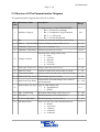
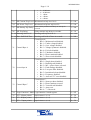
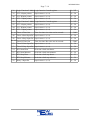
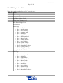
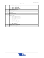
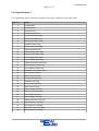
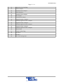
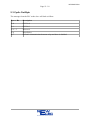
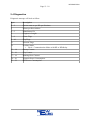
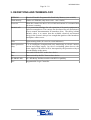
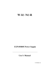
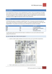
KE-PROFI-DP0
Page 1 / 18
KE-Relay or KD-Relay
Profibus DPV0
Communication Module
User Manual
KE-PROFI-DP0
Version 01.04
(NE_NC-KE-PROFI-DP0_MAN_01_10_FN04)
28 June 2010
NewElec Pretoria (Pty) Ltd
Head Office: c/o 298 Soutter street & Maltzan street
Pretoria West
South-Africa
0182
GPS: 25°45'12''S 28°09'46''E
Http://www.newelec.co.za
KE-PROFI-DP0
Page 2 / 18
Content
1. ABSTRACT............................................................................................................................3
2. SPECIFICATIONS.................................................................................................................4
2.1 Technical Specifications of KE-PROFI-DP0....................................................................4
2.2 Structure Of The Parametrization Telegram.....................................................................5
2.2.1 KE-Relay Pointer Table.............................................................................................8
2.2.2 Input Pointers 1 .......................................................................................................10
2.3 Cyclic Out Byte...............................................................................................................12
2.4 Diagnostics......................................................................................................................13
3. DEFINITIONS AND TERMINOLOGY..............................................................................14
4. FUNCTIONAL DESCRIPTION..........................................................................................15
5. OPERATING INSTRUCTIONS...........................................................................................16
5.1 Getting Started................................................................................................................16
5.1.1 Setting Up The KE-PROFI-DP0..............................................................................16
5.1.2 Installing Of NC-MK1-PROFI-DP1 GSD File........................................................16
6. DIAGRAMS.........................................................................................................................17
6.1 Block Diagram of NC-MK1-PROFI-DP1......................................................................17
7. PROFIBUS GSD REGISTERED.........................................................................................18
KE-PROFI-DP0
Page 3 / 18
1. ABSTRACT
The KE-PROFI-DP0 (KE or KD-Relay Profibus DPV0) acts as a translator between the
Profibus SCADA and the KE or KD-Relay. It is advisable to read the KE or KD user manual,
as some of the topics will require knowledge on the KE or KD. It is also advisable to have
knowledge on profibus. Information on profibus can be found at the web site
www.profibus.com.
The communication protocol between the KE-PROFI-DP0 and SCADA is Profibus DPV0
class 1. Communication protocol between the KE-PROFI-DP1 and the KE or KD Relay is a
NewElec proprietary protocol. Enabling the PLC to communicate with the KE or KD-Relay
via Profibus DPV0.
KE-PROFI-DP0
Page 4 / 18
2. SPECIFICATIONS
2.1 Technical Specifications of KE-PROFI-DP0
General Data
NC-MK1PROFI-DP0
Mounting Positions
Allowed Ambient Temperature
Humidity
Power Supply
Consumption
Communication Mediums
Profibus
Indication
Lights
Protocol
Baud Rate
Cable Length @ Baud Rate
Termination Resistor
(Termination resistors must be
connected at the beginning and
end of bus)
Type
LED Indications
●
●
●
●
●
●
●
●
●
●
●
●
●
●
●
●
External module.
Operation : 0 ºC to +60 ºC
< 87%
220 Vac
110 Vac
180 mA
Profibus
RS232
Profibus DPV0
9600 bit/s to 12 Mbit/s
1200 m @ 9600 bit/s to 45450 bit/s
1000 m @93.75Kbit/s to 187.5Kbit/s
400 m @ 500 Kbit/s
200 m @ 1.5 Mbit/s
100 m @ 3 Mbit/s to 12 Mbit/s
220 Ohm.
● Light Emitting Diode (LED)
● SCADA Communication
● KE or KD Communication
KE-PROFI-DP0
Page 5 / 18
2.2 Structure Of The Parametrization Telegram
The parametrization telegram data will look as follow:
Byte Parameter Name
Addr
Description
1
Profibus Config A
Configuration byte of the KE-PROFI-DP0:
• Bit 0 = Parametrize Settings.
• Bit 1 = Parametrize Logic Function.
• Bit 2 ~ 6 = Reserved.
• Bit 7 = Fail Safe Disabled.
2
Din
Amount of words from the Relay to the SCADA.
3 ~ 7 Word 1 ~ 5 To SCADA Pointer to KE-Relay Pointer Table (2.2.1).
Range
Set
1~5
0 ~ 12
8
Unbalance Trip Level
Trip level for unbalance in %.
9
Unbalance Trip Delay
Unbalance trip delay in seconds.
0~99
10
Voltage selection
Select the line voltage of the relay.
• 0 = Auto.
• 1 = 110 Vac.
• 2 = 400 Vac.
• 3 = 525 Vac.
• 4 = 1050 Vac.
0~4
11
Volt. Sym. Trip Level
Voltage symmetric trip level in %.
0 ~ 100
12
Starts Per Hour
Amount of starts that can be taken in a hour.
1 ~ 30
13
Consecutive Starts
Amount of starts to be take after a failed start attempt.
1~3
14 ~ 15 Earth Leak Trip Level
Earth leakage trip level in mA.
16 ~ 17 Earth Leak Trip Delay
Delayed time for earth leakage in ms with 50
ms incremental.
0 ~ 100
0 ~ 999
100 ~ 1000
Earth Leakage Trip Type Type of earth leakage trip.
18
•
•
0 = Instantaneous.
1 = IDMT.
0~1
19
Max. Load Setting
Maximum load setting of the relay in %.
10 ~ 100
20
TC Curve
Thermal capacity curve selected in %.
3 ~ 40
21
TC Reset Threshold
Thermal capacity reset level in %.
1 ~ 10
22
ML Reset Timer
Time to reset the relay after minimum load trip.
• 0 = Manual.
• 1 = 10 Seconds.
• 2 = 5 Minutes.
• 3 = 10 Minutes.
• 4 = 20 Minutes.
0~9
KE-PROFI-DP0
Page 6 / 18
•
•
•
•
•
5 = 30 Minutes.
6 = 45 Minutes.
7 = 1 Hour.
8 = 3 Hours.
9 = 6 Hours.
23
ML Current Trip Level Minimum load trip level in %.
0 ~ 100
24
ML Power Trip Level
0 ~ 100
25
ML Startup Trip Delay seconds.
1 ~ 200
26
ML Trip Delay
0 ~ 10
Minimum load power trip level %.
Time to delay minimum load trip at start up in
Delay run time trip delay in seconds.
27 ~ 28 Running Stall Level
Running stall trip level in %.
29 ~ 30 Run. Stall Hold Time
Running stall hold off time in seconds.
110 ~ 300
0 ~ 200
Control Byte A
Control byte A:
• Bit 0 = Minimum load disabled.
• Bit 1 = Under voltage disabled.
• Bit 2 = Over voltage disabled.
• Bit 3 = Voltage Symmetric disabled.
• Bit 4 = Fail safe disabled.
• Bit 5 = Unbalance disabled.
• Bit 6 = Phase rotation disabled.
• Bit 7 = Short circuit disabled.
Control Byte B
Control byte B:
• Bit 0 = Single phase disabled.
• Bit 1 = Running stall disabled.
• Bit 2 = ML = power factor selected.
• Bit 3 = Earth leakage disabled.
• Bit 4 = Low pass filter disabled.
• Bit 5 = Insulation lockout disabled.
• Bit 6 = Frequency disabled.
• Bit 7 = Auto calc. TC reset disabled.
33
Control Byte C
Control Byte C:
• Bit 0 = Starts per hour disabled.
• Bit 1 = Phase rotation reversed.
• Bit 2 = Vectorial stall disabled.
• Bit 3 = Auto reset.
• Bit 4 ~ 7 = Reserved.
34
Logic Function 1 Mask Logic function 1 mask register.
35
LF 1 A Input pointer
Input Pointers 1 (2.2.2).
0 ~ 50
36
LF 1 B Input pointer
Input Pointers 1 (2.2.2).
0 ~ 50
37
LF 1 C Input pointer
Input Pointers 1 (2.2.2).
0 ~ 50
31
32
0 ~ 255
KE-PROFI-DP0
Page 7 / 18
38
Logic Function 2 Mask Logic function 2 mask register.
39
LF 2 A Input pointer
Input Pointers 1 (2.2.2).
0 ~ 50
40
LF 2 B Input pointer
Input Pointers 1 (2.2.2).
0 ~ 50
41
LF 2 C Input pointer
Input Pointers 1 (2.2.2).
0 ~ 50
42
Logic Function 3 Mask Logic function 3 mask register.
43
LF 3 A Input pointer
Input Pointers 1 (2.2.2).
0 ~ 50
44
LF 3 B Input pointer
Input Pointers 1 (2.2.2).
0 ~ 50
45
LF 3 C Input pointer
Input Pointers 1 (2.2.2).
0 ~ 50
46 ~ 47 Timer A Time Out
Time for timer A to time out in seconds.
0 ~ 255
0 ~ 255
0 ~ 3000
48
Timer A Start Input Ptr Input Pointers 1 (2.2.2).
0 ~ 50
49
Timer A Stop Input Ptr Input Pointers 1 (2.2.2).
0 ~ 50
50 ~ 51 Timer B Time Out
Time for timer B to time out in seconds.
0 ~ 3000
52
Timer B Start Input Ptr Input Pointers 1 (2.2.2).
0 ~ 50
53
Timer B Stop Input Ptr Input Pointers 1 (2.2.2).
0 ~ 50
54
RTC Start Hour
Real time clock start hours.
0 ~ 23
55
RTC Start Minutes
Real time clock start minutes.
0 ~ 59
56
RTC Stop Hour
Real time clock stop hours.
0 ~ 23
57
RTC Stop Minutes
Real time clock stop minutes.
0 ~ 59
58
Relay 2 Input Ptr
Input Pointers 1 (2.2.2).
0 ~ 50
KE-PROFI-DP0
Page 8 / 18
2.2.1 KE-Relay Pointer Table
Values that can be routed to for the PLC words in 1 to 5.
Address Name
0
TC remaining
1
Current Level.
2
Red Phase Voltage Level.
3
White Phase Voltage Level.
4
Blue Phase Voltage Level.
5
Actual Power
6
Alarm Flags
• Bit 0 = In Service.
• Bit 1 = Earth Leakage.
• Bit 2 = Over Current.
• Bit 3 = Running Stall.
• Bit 4 = Unbalance.
• Bit 5 = Single Phase.
• Bit 6 = Minimum Load.
• Bit 7 = Short Circuit.
• Bit 8 = Voltage Present.
• Bit 9 = Over Voltage.
• Bit 10 = Under Voltage.
• Bit 11 = Voltage Symmetric.
• Bit 12 = Insulation Lockout.
• Bit 13 = Low Frequency.
• Bit 14 = High Frequency.
• Bit 15 = Earth Fault.
7
Trip Flags
• Bit 0 = Over Current.
• Bit 1 = Running Stall.
• Bit 2 = Unbalance.
• Bit 3 = Single Phase.
• Bit 4 = Minimum Load.
• Bit 5 = Short Circuit.
• Bit 6 = Phase Rotation.
• Bit 7 = Earth Fault.
• Bit 8 = Over Voltage.
• Bit 9 = Under Voltage.
• Bit 10 = Voltage Symmetric.
• Bit 11 = Insulation Lockout..
KE-PROFI-DP0
Page 9 / 18
•
•
•
•
Bit 12 = Low Frequency.
Bit 13 = High Frequency.
Bit 14 = Earth Fault.
Bit 15 = Starts Per Hour.
8
Voltage Symmetric Level
9
Earth Leakage Level.
10
Frequency
11
Insulation Lockout
12
Function Flags.
• Bit 0 = Logic Function 1.
• Bit 1 = Logic Function 2.
• Bit 2 = Logic Function 3.
• Bit 3 = Timer A.
• Bit 4 = Timer B.
• Bit 5 = Real Time Clock.
• Bit 6 = Main Trip Relay.
• Bit 7 = Relay 2.
13
Apparent Power Consumption
14
Real Power Consumption
KE-PROFI-DP0
Page 10 / 18
2.2.2 Input Pointers 1
It is signals that can be routed to the inputs of the logic functions, timers and relays.
Address
Name
0
Constant Zero
1
Constant One
2
In Service Flag
3
Voltage Present Flag
4
Over Current Alarm Flag
5
Short Circuit Alarm Flag
6
Running Stall Alarm Flag
7
Unbalance Alarm Flag
8
Single Phase Alarm Flag
9
Earth Fault Alarm Flag
10
Earth Leakage Alarm Flag
11
Minimum Load Alarm Flag
12
Over Voltage Alarm Flag
13
Under Voltage Alarm Flag
14
Voltage Symmetric Alarm Flag
15
High Frequency Alarm Flag
16
Low Frequency Alarm Flag
17
Insulation Lockout Alarm Flag
18
Over Current Trip Flag
19
Short Circuit Trip Flag
20
Running Stall Trip Flag
21
Unbalance Trip Flag
22
Single Phase Trip Flag
23
Earth Fault Trip Flag
24
Earth Leakage Trip Flag
25
Minimum Load Trip Flag
26
Over Voltage Trip Flag
27
Under Voltage Trip Flag
28
Voltage Symmetric Trip Flag
29
High Frequency Trip Flag
30
Low Frequency Trip Flag
31
Insulation Lockout Trip Flag
32
Phase Rotation Trip Flag
KE-PROFI-DP0
Page 11 / 18
33
Starts Per Hour Trip Flag
34
Timer A Output
35
Inverted Timer A Output
36
Timer B Output
37
Inverted Timer B Output
38
RTC Output
39
Inverted RTC Output
40
Logical Function 1 Output
41
Inverted Logical Function 1 Output
42
Logical Function 2 Output
43
Inverted Logical Function 2 Output
44
Logical Function 3 Output
45
Inverted Logical Function 3 Output
46
Restart Flag
47
Frozen Contact Flag
48
PLC Bit 0
49
PLC Bit 1
50
TC > TC warning level.
KE-PROFI-DP0
Page 12 / 18
2.3 Cyclic Out Byte
The message from the PLC to the slave will look as follow:
Byte :: Bit
Description
0::0
PLC bit 0
0::1
PLC bit 1
0::2 ~ 5
Reserved
0::6
Reset Relay
0::7
Fail safe communication between relay and slave is disabled
KE-PROFI-DP0
Page 13 / 18
2.4 Diagnostics
Diagnostic message will look as follow:
Byte
Description
0~2
Station status as per DP specifications.
3
Master profibus address.
4~5
Manufacture ID.
6
Diagnostic Length.
7~8
Alarm Flags.
9 ~ 10
Trip Flags.
11
Function Flags
12
Profibus Status.
• Bit 0 = Communication failure with KE or KD-Relay.
13 ~ 14
Startup Counter.
15 ~ 16
Trip Counter.
17 ~ 18
Running Hour Counter.
19 ~ 20
Apparent Power Consumption.
21 ~ 22
Real Power Consumption.
KE-PROFI-DP0
Page 14 / 18
3. DEFINITIONS AND TERMINOLOGY
EEPROM
Electrical Erasable Programmable Read Only Memory (non volatile)
Flash memory
Similar to EEPROM (only block write - non volatile)
In service
When the current rise above 10% of full load current it is assumed that
the motor is running.
Intrinsic safe
It is a protection technique for safe operation of electronic equipment in
explosive atmospheres. The concept was developed for safe operation of
process control instrumentation in hazardous areas. The theory behind
intrinsic safety is to ensure that the available electrical and thermal
energy in the system is always low enough that ignition of the hazardous
atmosphere cannot occur.
LED
Light emitting diode (It is used as visual indicators)
Motor protection
relay
It is an intelligent (computerized) unit monitoring an electric motor's
current and voltage supply. In case of overloading, phase lost etc. the
power supply of the motor will be interrupted by the protection relay to
prevent damage to the motor.
Dout
Data send from the PLC to the slave device.
Din
Data received by the PLC from a slave device.
KE-PROFI-DP1
KE / KD-Relay Profibus module with DPV0 capability.
PLC
Programmable Logic Controller.
KE-PROFI-DP0
Page 15 / 18
4. FUNCTIONAL DESCRIPTION
The KE-PROFI-DP0 can be broken down into the following function blocks:
• Micro-Controller
• KE / KD-Relay Interface.
• Profibus Interface.
• Light Emitting Diodes (LED)
Micro-Controller – Is the core of the system. The micro-controller ensures that the operation
of the KE-PROFI-DP0 gets executed. The micro-controller acts as a bridge between the KE /
KD-Relay and the PLC.
KE / KD-Relay Interface – Is the communication bus between the KE / KD-Relay and KEPROFI-DP0. With the KE / KD-Relay interface it is possible for the two micro-controllers KE
/ KD-Relay and KE-PROFI-DP0 to exchange data.
Profibus Interface – Allows the KE / KD-Relay to communicate with the PLC. With the
profibus interface it is possible to update the KE-PROFI-DP0 with new values as well as the
PLC.
Light Emitting Diodes – Allows the KE-PROFI-DP0 to indicate conditions to the operator.
KE-PROFI-DP0
Page 16 / 18
5. OPERATING INSTRUCTIONS
5.1 Getting Started
5.1.1 Setting Up The KE-PROFI-DP0
Following must be done via the KE-PROFI-DP0 front-end:
• Connect the KE-PROFI-DP0 to the front-end via the RS232 port.
• Set the address of the KE-PROFI-DP0.
• Transmit the data to the KE-PROFI-DP0.
5.1.2 Installing Of NC-MK1-PROFI-DP1 GSD File
Following steps must be taken to install the GSD File:
• Import the NewElec NEWEFF881.gsd into the STEP7 GSD directory.
• Insert the KE-PROFI-DP0 device into the hardware configuration of the STEP7 program.
• Set the KE-PROFI-DP0 stations address in the PLC hardware configuration. The address must
match the address in the KE-PROFI-DP0.
•
Set the parametrization of the KE-PROFI-DP0.
• Make sure that the cyclic Din matches those of the KE-PROFI-DP0 parametrization bytes.
KE-PROFI-DP0
Page 17 / 18
6. DIAGRAMS
6.1 Block Diagram of NC-MK1-PROFI-DP1
KE / KD-Relay
Interface
Micro-Controller
With Memory
Profibus
Interface
LED
KE-PROFI-DP0
Page 18 / 18
7. PROFIBUS GSD REGISTERED
----ooOoo----