1
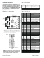
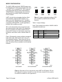
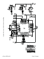
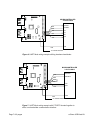
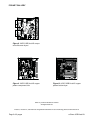
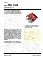
e-Gizmo
VNC2
USB Host
Hardware Manual Rev 1r0
T
hese days, just about anything that can be
connected to a PC do so using a USB port. Before USB came into existence, adding peripherals
to a PC is a job that requires the service of a skilled
technician. With USB connectivity, attaching new
peripherals became just as easy as plugging an appliance into an AC outlet. Any PC owner can install
new USB peripherals, no special skills needed.
Not surprisingly, PC owners now have a huge
selection of USB peripheral devices to choose
from. From basic devices such as USB mouse and
keyboards, to advance laboratory measuring equipment; even machines. And with equally countless of
USB manufacturers competing to sell you the same
products, prices goes as low as it can be.
With plentiful and sometimes dirt cheap USB
devices all around the place, one may expect to
see DIY microcontroller experimenters using these
devices in their projects. But that is not what is happening. Experienced experimenters know all too
well the reasons why. One is the heavy and lengthy
programming code involved just to get the microcontroller to talk with USB devices. Layers upon
layers of procedures and protocols are required.
Even if the programmer has the patience (and all
the time in the world) to do the coding, popular 8-bit
microcontrollers simply lacks the processing power
and memory capacity required to do such low level
USB tasks.
Fortunately, one company, Future Technology
Devices International FTDI, finally provided an easy
with the introduction of their Vinculum chip. The
second generation Vinculum II chip is a user programmable USB host chip with two integrated USB
ports. FTDI provides a free software developer’s kit
and libraries for advance users who may want to
customize the VNC2, and build a dedicated function USB host in no time at all.
For the rest of us who just want an easy to use,
general purpose USB host, FTDI has prepared a
Page 1 of 9 pages
e-Gizmo USB Host kit is built around FDTI
Vinculum VNC2 chip, and is preloaded
with V2DAP firmware.
Features
Chip:
VNC2-48Q
USB Ports : Two USB Type A sockets
Interface:
UART,SPI jumper selectable
Debugger Port: 1
I/Os:
25
Power Input: 5VDC
DC Power Output: 3.3V @ 100mA
Preloaded Firmware: V2DAP
PCB Size: 51W x 51L mm
general purpose USB firmware for us, the Vinculum
Disk and Peripherals firmware V2DAP. This firmware is preloaded with the Vinculum USB Host kit
as sold by e-Gizmo. With this kit, microcontroller
experimenters can now easily incorporate USB
hosts function with their circuits working with a
number of USB devices, such as USB flash disk
(BOMS devices), joystick (HID devices), including
devices using FDTI USB to serial bridge chips and
CDC devices.
e-Gizmo USB Host Kit
HARDWARE REFERENCE
Table 1 LED Indicators
The following section briefly describes the pin-out
and jumper configurations of the VNC2 USB Host.
For a more complete description, please refer to
the Vinculum VNC2-48 Development Module Datasheet. Downlink link to this document is listed in
page 8 of this manual.
COMP
D1
POWER
+5V Power Indicator
D3
USB2/P2
USB PORT2 selected
D4
USB1/P1
USB PORT1 selected
PIN
Figure 1. VNC2 USB Host component layout
showing only the LED indicators, USB and I/O
ports, plus a few more components.
Pin 1
Pin 34
Figure 2. I/O Port pin-out. Some of the I/Os -depending on the mode selected - are used by the
V2DAP firmware for some specific function.
e-Gizmo USB Host Kit
Description
Table 2. I/O PORT P2
TERMINALS & INDICATORS
ID
ID
VNC2 ID
REMARKS
1
+3V3
+3V3 OUT
2
GND
3
N.C.
4
IO11
5
N.C.
6
IO10
BCBUS2
5V safe I/O, SPI_MMISO
7
IO8
BCBUS0
5V safe I/O, SPI_MCLK
8
IO9
BCBUS1
5V safe I/O, SPI_MMOSI
9
IO6
BDBUS6
LED D3, SPI_MISO
10
IO7
BDBUS7
5V safe I/O, SPI_SS
11
IO4
BDBUS4
5V safe I/O, SPI_CLK
12
IO5
BDBUS5
LED D4, SPI_MOSI
13
IO2
BDBUS2
5V safe I/O
14
IO3
BDBUS3
5V safe I/O
15
IO0
BDBUS0
5V safe I/O
16
IO1
BDBUS1
5V safe I/O
17
IO24
ACBUS4
5V safe I/O
18
GND
GND
Ground
19
IO22
ACBUS2
5V safe I/O
20
IO23
ACBUS3
5V safe I/O
21
IO20
ACBUS0
5V safe I/O,TX_Active
22
IO21
ACBUS1
5V safe I/O
23
IO18
ADBUS6
5V safe I/O, DCD
24
IO19
ADBUS7
5V safe I/O, RI
25
IO16
ADBUS4
5V safe I/O, DTR
26
IO17
ADBUS5
5V safe I/O, DSR
27
IO14
ADBUS2
5V safe I/O, RTS
28
IO15
ADBUS3
5V safe I/O, CTS
29
IO12
ADBUS0
5V safe I/O, TXD
30
IO13
ADBUS1
5V safe I/O, RXD
31
GND
GND
PWR Ground
32
GND
GND
PWR Ground
33
+5V
PWR
+5V Power input
34
+5V
PWR
+5V Power input
GND
key/no connection
BCBUS3
5V safe I/O, SPI_MSS
key/no connection
Page 2 of 9 pages
MODE CONFIGURATION
The VNC2 USB Host kit with V2DAP firmware can
be interfaced to the host microcontroller three ways
– by UART, SPI, or parallel FIFO. FIFO, however,
is not supported in this kit when loaded with the
V2DAP firmware. Advanced user may create his
own firmware (or modify V2DAP) to implement
FIFO if needed.
UART is by far the most popular interface. Most
microcontroller supports UART interface. It is
easy to use and supported by most C compilers
I/O functions (e.g. printf()), but is generally slower
compared to SPI and FIFO. In most applications,
however, this is seldom an issue.
SPI, on the other hand, is fast, and is best used
with microcontrollers with built-in SPI peripherals.
Not all C compilers can readily redirect I/O functions to SPI, however. In some cases, users have
to write his own code in order to transfer data via
SPI.
Figure 3 illustrates the jumper settings corresponding to each mode. Each mode uses a set of I/O
for its physical interface. These reserved I/Os are
shown in Figure 4 labeled with their assigned functions. All unused I/Os are available for user defined
functions.
PIN1
PIN1
PIN34
Figure 3. Jumper configurable settings. FIFO
is not available by default with the VDAP2
firmware.
Table 3. Jumper Settings
Note: These settings are valid for V2DAP & VNC1L
compatible firmware only.
K1
K2
MODE
2-3
2-3
UART
1-2
1-2
UART
1-2
2-3
SPI
2-3
1-2
FIFO (see text)
PIN34
PIN1
PIN34
Figure 4. Equivalent I/O pins assignment under UART and SPI Mode. SPI can
be configured to work as a master or a slave. All other unused I/Os in a particular mode are available for user applications.
Page 3 of 9 pages
e-Gizmo USB Host Kit
Table 4. UART Mode I/O Assignment
PIN
21
22
23
24
25
26
27
28
29
30
ID
IO20
IO21
IO18
IO19
IO16
IO17
IO14
IO15
IO12
IO13
FUNCTION
TX_ACTIVE
TYPE
Output
DESCRIPTION
Enable Transmit Data for RS485 interface
DCD
RI
DTR
DSR
RTS
CTS
TXD
RXD
Input
Input
Output
Input
Output
Input
Output
Input
Data Carrier Detect control input
Ring Indicator Control input
Data Terminal Ready output, Data Acknowldge output
Data Set Ready input, Data Request Input
Request to Send Control output
Clear to send Control Input
Data Tx Output
Data Rx Input
Table 5. SPI SLAVE Mode I/O Assignment
PIN
9
10
11
12
ID
IO6
IO7
IO4
IO5
FUNCTION
SPI_MISO
SPI_SS
SPI_CLK
SPI_MOSI
TYPE
Output
Input
Input
I/O
DESCRIPTION
Master In Slave Out, Data from slave to master
Slave chip select, active low
Slave Clock Input
Master Out Slave In, Data from master to slave
Table 6. SPI MASTER Mode I/O Assignment
PIN
4
5
6
7
8
ID
IO11
N.C.
IO10
IO8
IO9
FUNCTION
SPI_MSS
TYPE
Output
DESCRIPTION
Master slave select, active low
SPI_MMISO
SPI_MCLK
SPI_MMOSI
Input
Output
Output
Master In Slave Out, Data from slave to master
Master Clock output
Master Out Slave In, Data from master to slave
e-Gizmo USB Host Kit
Page 4 of 9 pages
DEVELOPING YOUR OWN FIRMWARE
SUPPORTED USB DEVICES
There are several reasons why you may want to
create your own firmware. For example, pre-packaged firmware may not readily function to some
USB device you need to connect with. With your
firmware in control, you can perform the necessary
tasks to make a successful connection. Furthermore, although the VNC2 is primarily intended for
USB hosting functions, its powerful 16-bit MCU
core can definitely do more. It is possible to build a
complete stand alone system without the aid of an
external microcontroller.
V2DAP supports five types of generic USB Devices:
Users who may like to build their own firmware may
program and debug the USB host through the Debug Port. The software developer’s tool Vinculum
II IDE and USB libraries can be downloaded from
FTDI website at no charge (registration is required).
FTDI VNC2 Debug Module is required. The VNC2
Debug Module is sold by authorized distributors
at a near bargain price. The VNC2 debug module
uses off the shelf FTDI components; you can build
one yourself if you so prefer. It is even possible to
change (update) the firmware with your compiled
code using just a USB Flash Disk. The VNC2 USB
Host does this automatically whenever it founds
an updated firmware version on your disk during
device detection. But there is a price to pay – without the VNC2 Debug Module, you won’t be able to
debug your firmware while in action.
Printer – USB Printers
BOMs- Bulk Only Mass Storage.
Example: USB Flash Disk, Camera
FTDI Peripherals – USB devices using FTDI
FT232,FT245, or FT2232 as USB to serial bridge.
HID – Generic USB Human Interface Devices
Example: Mouse, Joystick, Keyboard.
HUB – USB port expander
CDC – Communication Class Devices
Example: MODEMs, Mobile Phones
Except for BOMs devices, any one or two of these
devices can be plugged either in USB port1 or USB
port2. BOMs class devices will work only with USB
Port2. USB Support is summarized in Table 8.
Table 8. USB Slave Peripherals (V2DAP Firmware)
Device Type
USB
PORT1
USB
PORT2
BOMS
Table 7. P1 Debug Port
FTDI Periphpherals
HID
PIN
1
2
3
4
ID
IO0
N.C.
GND
RST
5
6
PRG
PWR
Remarks
Debugger Interface
No connection, key
Debug GND
RST-PRG used together tp program firware into the VNC2
Printer
Hub
CDC
5V Source
Note: Port layout is compatible with FTDI VNC2
Debug Module.
Page 5 of 9 pages
e-Gizmo USB Host Kit
Figure 5. Schematic Diagram of the VNC2 USB Host.
Page 6 of 9 pages
e-Gizmo USB Host Kit
Figure 6. UART Mode wiring example utilizing hardware handshake.
Figure 7. UART Mode wiring example with CTS-RTS shorted together to
effect a no-handshake communication interface.
Page 7 of 9 pages
e-Gizmo USB Host Kit
UART MODE APPLICATION EXAMPLE
UPDATING AND CHANGING FIRMWARES
Two possible application wiring examples in UART
mode is shown in Figure 6 and 7. Hardware handshake RTS-CTS is used in Figure 6. This is the
preferred configuration, and is in fact necessary if
you plan to use high baud rates and/or where large
volume of data packets needs to be transferred in
between the host microcontroller and the USB Host
kit. Hardware handshake helps in preventing buffer
overruns that will eventually lead to data loss.
You don’t need any special programming hardware
to update or even load your own firmware in the
USB Host kit. Just copy the precompiled firmware
in the root directory of your USB flash disk, and
then plug the USB flash disk in USB port2 of the
USB Host kit. The VNC2 will automatically copy the
firmware to its internal flash.
For less critical applications, you may use simpler
no-handshake mode by shorting the USB Host CTS
and RTS line together as shown in Figure 7.
Complete hardware and firmware documentation
for the VNC2 USB host can be downloaded from
FDTI website. Recommended must reads are listed
below:
You can pass data to the USB device through the
USB host either by letting the USB Host talk to the
USB device and get the data for you in Command
Mode, or directly to the USB device (raw transfer)
in Data Mode. To switch the USB Host in Data
Mode, drive its CTS input to GND (logic “0”) level.
The USB Host sets its DTR pin to logic “1” when it
enters Data Mode.
There are applications that do not require the USB
Host to enter the Data Mode. In such cases, you
can simply omit the DSR and DTR connection.
Leaving these pins open puts the USB Host in
Command Mode.
The default UART communication parameters of
the USB host are:
MUST READ
Vinculum Firmware User Manual Rev 2.05
http://www.ftdichip.com/Firmware/Precompiled/UM_
VinculumFirmware_V205.pdf
V2DIP2-48
http://www.ftdichip.com/Support/Documents/DataSheets/Modules/DS_V2DIP2-48.pdf
Hardware details in this documentation applicable
to the USB Host Kit.
More application information for users who want to
know more:
http://www.ftdichip.com/FTSupport.htm
Baud Rate:
Data :
Stop Bit :
Parity:
Handshake:
9600
8 Bits
1
None
RTS-CTS
You can change the baud rate settings while in
Command Mode. Speed as high as 3Mbps is supported. Now you see the USB Host in UART Mode
is not that slow after all.
PRECOMPILED FIRMWARES
V2DAP Disk and Peripheral firmware is the most
general purpose firmware and supports most USB
devices on Port1 and Port2. As of this time of writing, there are two more specialized precompiled
firmware- V2DPS and V2F2F Disk or Peripheral
Firmware. Details of these firmwares are described
in the Vinculum Firmware User Manual Rev 2.05.
Latest VNC2 Firmware releases can be downloaded from:
http://www.ftdichip.com/Firmware/Precompiled.htm
e-Gizmo USB Host Kit
Page 8 of 9 pages
PCB ART GALLERY
Figure 8. VNC2 USB Host Kit component silkscreen layout.
Figure 9. VNC2 USB Host Kit copper
pattern component side.
Figure 10. VNC2 USB Host Kit copper
pattern bottom layer.
©2011 by e-Gizmo Mechatronix Central
All Rights Reserved
Vinculum, Vinculum II, and VNC2 are all registered trademarks of Future Technology Devices International Ltd.
Page 9 of 9 pages
e-Gizmo USB Host Kit