1
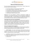
User’s manual
Catalog # 6110FS
CONTENTS
General Overview
2
Meter Dimensions
2
Taking Compaction Measurements
3
Meter Operation
SC 900 Soil
Compaction Meter
Spectrum
Technologies, Inc.
3-4
Connecting to a Computer
4
Connecting to a GPS Unit
5
Depth Sensor
5
Calibration
6
Meter Settings
6
Measurement Procedure
7
Warning Messages
8
Data Management
9
Determining When to Replace Cone
10
Specifications
11
Appendix 1: Time Zone Corrections
11
Warranty
12
This manual will familiarize you with the features and operation of your new
Field ScoutTM SC 900 Soil Compaction Meter. Please read this manual
thoroughly before using your instrument. For customer support, or to place
an order, call Spectrum Technologies, Inc.
(800)248-8873 or (815) 436-4440
between 7:30 am and 5:30 p.m. CST,
FAX (815)436-4460,
E-Mail: [email protected].
www.specmeters.com
Spectrum Technologies, Inc at 23839 W Andrew Rd.
General overview
Meter dimensions
Thank you for purchasing the Field ScoutTM SC 900 Soil Compaction
Meter. This manual describes the features and operation of the meter.
The following are the dimensions of the SC 900 Soil Compaction Meter.
Soil compaction prevents moisture penetration, reduces fertilizer and
chemical uptake and hinders plant root growth. In some cases, yield
losses can run as high as 30% due to compaction. This new electronic
soil compaction meter is the most versatile compaction meter on the
market. Soil depth readings are determined by a sonic depth sensor.
Cone index values are measured by a load cell sensor and can be displayed in PSI or kPa.
12”
7.25”
The Field Scout’s shaft-mounted probe allows the user to easily and
rapidly take many measurements. The shaft can be dissembled into 2
pieces for easy storage and transport. The meter’s built-in datalogger
can record data from several sites and eliminates the need to record
data manually. Through the software, the user can download the data,
change the logger settings and configure the meter.
Meter
8.5”
Shaft
Connection
19.75”
Cone Tip
2
Taking Compaction
Measurements
Meter operation
The ON switch turns the meter/datalogger on
and off. When the meter is turned on, it will display the battery status for 3 seconds. For the
ON
next 3 seconds, it will display how much logger
memory has been used and, if the logger was enabled in the software, whether the GPS signal was found. If a GPS
signal is found, latitude and longitude data will be included in the data
file.
The SC 900 is a state-of-the-art electronic cone penetrometer for use
in soil density, trafficability and compaction studies. This soil compaction instrument measures cone index data, logs the data and allows
the user to review the data to make soil management decisions.
It is recommended that compaction measurements be taken after a
rain, or in the spring when the soils have good moisture content.
Measuring soil compaction in dry soil conditions will not yield meaningful results.
Logger 75% Full
GPS=Yes DGPS=No
The SC 900 compaction meter should be used before tillage to determine where the compacted areas of a field/plot are. Once the compacted areas, along with compaction depths, have been determined, a
much more effective tillage system can be employed.
Logger 75% Full
No GPS Found
Sample meter power-up screens with datalogger
enabled: left screen indicates GPS signal was found.
The meter will then be ready to take readings (see “Measurement Procedure” pg. 7).
The unit works as an efficient diagnostic tool as well as a management
unit after the tillage operation has been performed. One can determine
how deep the soil has actually been worked and if the tillage operation
has solved the compaction problems.
Note: If you are using GPS, but the meter doesn’t find the GPS signal
when powering up, the meter will not search for the GPS signal when
taking readings. Turn the meter off and on so it can look for the GPS
signal. Once the signal is found, GPS information will be included in
the data file until the signal is lost or the GPS unit is disconnected
from the meter.
0010 PSI 00 IN
Logger = OFF
If, when powered up, the screen indicates the data logger is not activated (see above screen), no data will be stored by the meter. The
data logger can be activated through the SC 900 software (see “Meter
Settings, pg. 12).
3
Meter operation (cont.)
Connecting to a Computer
SC 900
data port
Immediately after the meter has successfully
taken a full profile measurement, but before
DELETE
measuring another profile, the DELETE button
will delete the profile before that has just been
sent to the datalogger. The screen will then display the following message:
Reading Deleted
REVIEW
START
The data port on the underside of the SC 900 meter (shown above) can
be accessed by removing the plastic screw. It is through this port that
the meter is connected to either a PC or to a GPS unit.
After measuring a profile, pressing the REVIEW button allows the user to see the cone
index value at each depth. As the button is
pressed, the display screen will scroll sequentially through the entire profile.
Connecting to a PC
The SC900 software comes with a gray PC interface cable. This cable
connects to the 9-pin serial port of your computer and to the meter’s
computer port. The meter’s configuration can be modified by clicking on the Logging Properties button (see “Meter Settings”, pg. 12).
The Com Port, Download and Clear Memory buttons are explained
in “Data Management” (pg. 9).
The START button readies the meter and datalogger to take a profile measurement. It must be
pressed before every attempted profile measurement.
4
Connecting to a GPS Unit
Depth Sensor
Cable Connections
A GPS/DGPS cable (item # 2950C) is required to connect the SC900
meter to a GPS unit. This cable has a 9-pin male connection and a
stereo pin that connects to the meter’s data port. You will also need a
cable that allows the GPS unit to connect to a 9-pin male serial port.
If this cable doesn’t come standard with your GPS unit, it should be
available from the manufacturer. This cable is generally used to upload information from a computer to the GPS unit. These components
should be connected as shown in figure X.
An ultrasonic sensor located at the
base of the meter is used to measure the depth of penetration. The
field of view extends about 30o
from the shaft. The sensor measures distance by emitting a sound
wave and measuring the travel
time of the first reflected wave.
Depth
Usually, this first reflection will
Sensor
come from the ground just adjacent to the shaft. However, if an
object with a surface oriented toward the sensor is within the field
of view, an erroneous depth measurement may be made. This can
lead to depth error messages (see
“Warning Messages” p. 15). If
possible, try to remove the object
and/or smooth the surface. Repositioning your feet and knees may
also eliminate these errors. If the
problem persists, use a flat target
surface with a hole slightly large
than the diameter of the cone to test the depth sensor and, if necessary,
to take measurements. This target should be about 1 foot wide and
can be made out of cardboard or something sturdier if more durability
is required. To test the sensor, lay the target on the ground and place
the shaft in the hole. Have another person slowly raise the target
while you verify the meter is incrementing the depth.
GPS Setting
Your GPS unit must be set for NMEA 0183 input/output messages. If
the meter has trouble receiving the GPS signal, check that it has the
following settings:
Data bits: 8
Baud rate: 4800 bps
Timing: 1 second
Stop bits: 1
Parity:
None
GGA data string
SC900
Meter
GPS
Unit
Spectrum
GPS/DGPS
Cable
GPS computer
interface cable
Connecting the SC900 meter to a GPS unit
5
Calibration
Meter Settings
The reading of the meter’s load cell can be recalibrated with the following procedure.
Logger Settings: The datalogger is enabled and disabled by checking
the first box. If the datalogger is enabled, it will search for a GPS signal when the meter is turned on. If a signal is found, position data will
be stored along with the soil moisture data. If no GPS signal is available when the logger is turned on, the logger will no longer look for
one when measuring and recording soil moisture data. If the second
box is checked, the logger will store the GPS value only if it has been
differentially corrected. If the differential correction is not found,
only the soil moisture value will be stored in the data file. A timezone correction should be entered in the third box. Appendix 1 (pg.
23) lists time zone corrections for several cities.
Note: During the calibration procedure, care must be taken to
ensure that the only force on the load cell is the weight of the meter itself.
1. Balance the meter in an upright position on a hard surface.
2. Press and hold the READ button.
3. With the READ button depressed, press and release the ON button. The LCD will count down from 5 to 1.
Measurement Units: The meter can be configured to display and record data in English units (Cone Index in PSI and depth in inches) or
SI units (Cone Index in kPa and depth in centimeters).
4. The meter should now read between 5 and 10 P.S.I. (35 - 70
Kpa). This reflects the weight of the meter itself.
Meter Settings
The Meter Settings screen in the Field Scout Soil Compaction Meter
software is used to configure the meter and datalogger for your specific application. This screen can be accessed by clicking on the Logging Properties button on the main software screen (see pg. 3). The
fields are described below.
Meter Name: The name given the meter will be the title on the first
line of the downloaded text file.
6
Measurement Procedure
Measurement Procedure
Recording the best quality data requires some practice. Your
objective is to uniformly push the probe into the ground using an even
motion. The programmed rate,specified in the ASAE standards, is
approximately 2 seconds per 2 inches. If this rate is exceeded, the
meter will show an Error display (see “Warning Messages” pg. 8).
5. Remove probe gently. If the profile was successfully measured,
the following message will be displayed.
Reading Complete
- -Review Mode- -
To take a profile measurement:
6. You can review compaction measurements increments by pushing
the Review button . You can also delete the profile by pushing the
Delete button. See “Meter Operation” (pg. 3) for details.
7. Press Start to ready the probe for the next measurement.
1. Push and release Start button.
2. Wait for LCD to display the profile information screen. The top
line shows the current cone index and the depth. At the surface
the depth will be zero. The second line indicates how many profiles have been taken. This resets to 1 every time the meter is
turned on.
Geo - Referencing Compaction Measurements:
0010 PSI 00 IN
N=1
To Geo-Reference, you will need to connect a GPS/DGPS unit to SC
900 and proceed as described above. The GPS format should be
NMEA 0183. See “Connecting to a GPS Unit” (pg. 5) for further details.
Profile Information Screen
3. Stand with your feet at least 4 to 6 inches from the probe tip. This
ensures the sonic depth sensor will measure accurately. Tall,
nearby objects or walls will also inhibit the ability of the depth
sensor to “see” the ground surface. If you are working in turf or
an especially uneven soil surface, you may need to use a target to
ensure reliable performance (see “Depth Sensor” p. 7). It is advisable to smooth the soil surface as much as possible before inserting the probe. As the probe is inserted into the soil, the depth
measurement on the display will increase in 1 inch increments.
The cone index will change in response to soil compaction differences.
4. Push probe into ground slowly and evenly so that there is not any
side stress on the shaft. If an error message is generated (see
“Warning Messages” pg. 8), start over by removing probe and
pushing the Start button.
7
Warning Messages
Warning Messages (Cont.)
If the meter is unable to successfully measure a soil compaction profile, it will display one of the following warning messages and no data
will be sent to the datalogger. In these instances, it is necessary to
withdraw the probe from the soil (if necessary) and hit the START
button to continue using the meter (see “Measurement Procedure” pg
7).
The maximum load the load
cell can withstand is 250
lbs (113 kg). Exceeding
this limit can cause permanent damage to the meter. The “Excessive Force”
warning message appears when 210 lbs (95 kg) or
more is applied to the load cell.
Start Over
Excessive Force
Warning Messages
The meter cannot begin taking
readings until the probe senses the
tip is at the soil surface. The meter
can sense a false non-zero depth if
the user’s feet are too close to the shaft, if an object such as a tree or
large plant is near the measurement area or if debris such as roots, soil
or leaf matter is clinging to the shaft.
Start Over
Depth > zero!
This error message indicates that the meter missed
a depth reading. This can
be caused by a momentary,
but rapid, insertion of the
probe into the soil or by an object such as a foot or a
knee suddenly coming into the field of view of the
sonic depth sensor.
Start Over
!! Depth Error !!
If the meter is inserted faster than
the speed allowed by the ASAE
standard (2 inches per 2 seconds),
the meter cannot compute the cone
index. You may see this message more often when taking readings in
areas with non-compacted zones beneath strongly compacted zones.
Start Over
Insertion too fast
Low Battery
8
Indicates the batteries need
to be changed. The battery
compartment is located beneath the face of the meter.
Data Management
Data Management (Cont.)
Com Port
The gray software cable connects the meter to the computer data port.
Select the Com Port that is connected to the computer data port.
Sample data showing results of data collected with and without GPS
activated. Note: GPS signal not found when recording first four sample numbers.
Download
To download data from the internal datalogger, turn the meter off and
connect the gray serial cable to the RS-232 port on the underside of
the meter. Click the Download button on the main software screen.
In the Save Data As screen, give the file a descriptive name and select
the location where it will be saved.
The data is stored in comma-delimited text files. These files can be
opened with text-editing software (e.g. Microsoft Word) or spreadsheet software (e.g. Excel).
The first two lines of the data file give the logger’s name and serial
number. The third line indicates that latitude and longitude are referenced to the 1984 World Geologic Survey datum. The fourth line
shows the cone index unit system. The fifth line shows the column
headings for the rest of the data file. Each row of data represents a
measurement profile.
Clear Memory
Data is not automatically removed from the logger memory after a
download. The Clear Memory button clears all data from the logger
memory.
Logging sessions are started and completed by turning the meter on
and off. The start of a logging session is indicated by the data line
“Logger Started”. If a GPS signal was found at the start of a logger
session a time stamp is included on the “Logger Started” line.
Meter Settings
Click this button to configure the datalogger. Refer to “Meter Settings” (p. 6) for more details.
9
Determining When to
Replace Cone
Determining When to
Replace Cone
Repeated soil sampling will wear down the metal cone. Periodically
measure the diameter of the cone using a dial caliper or micrometer
that allows you 0.001-inch measurements.
When you are doing comparative analysis of the readings in a field or
a plot, the measurements will be consecutive. The amount of wear of
the cone will not be a factor. In this case, it is recommended that the
cone be replaced when the shoulder is not easily recognizable as a
shoulder anymore.
Place the caliper/micrometer on the shoulder of the cone. Figure 1
shows the proper placement and Figure 2 the layout of the shoulder.
Figure 3
Figure 1
Figure 2
Shoulder
New:
0.505"
Replace the cone as follows:
1. Lay meter on its side
2. Unscrew worn cone by hand or with a
pair of pliers
3. Attach new cone into meter shaft
4. Tighten to a snug fit with hands or
pliers. Be careful not to imprint the cone
with pliers.
The determination as to when to replace the cone will depend on how
the user is applying the meter.
If you are using the meter to get absolute compaction readings,
replace the cone when there is a “wear factor” of 3%. Three percent
wear affects the cone index measurements by 5%. A new cone has a
diameter of 0.505“, see Figure 3. When the cone diameter reaches
0.490“ (3% wear), replace the cone.
Replacement cones can be ordered from Spectrum
Technologies or an authorized Spectrum Dealer.
10
Specifications
Measurement
Units
Cone Index (PSI or kPa)
Resolution
1” (2.5 cm), 5 PSI (35 kPa)
Accuracy
±0.5” (±1.25 cm), ±15 PSI (±103 kPa)
Range
0 - 18” (0 - 45 cm),
0 - 1000PSI (0 - 7000 kPa)
Maximum
Insertion Speed *
72 in/min (182 cm/min)
Maximum
Applied Load *
210 lbs
Power
2 AA alkaline batteries
Approximately 12 month life
Logger Capacity
772 profiles without GPS,
579 profiles with GPS/DGPS
Display
16 character, 2 line LCD
Weight
2.75 lbs. (1.25 kg)
Appendix 1
Time zone corrections
Time Zone
Correction
0
Dublin, Lisbon, London
3
Rio de Janeiro, Montevideo
4
Asuncion
5
7
Atlanta, Indianapolis, New York, Ottawa, Bogota,
Montreal, Toronto
Guatemala City, Houston, New Orleans, Chicago,
Mexico City, Winnipeg
Phoenix, Denver, Edmonton
8
San Francisco, Los Angeles, Vancouver
9
Anchorage
10
Honolulu
11
Wellington
13
Adelaide, Melbourne, Sydney
14
Vladivostok, Brisbane
15
Seoul, Tokyo
16
Beijing, Hong Kong, Manila, Singapore, Taipei
17
Hanoi, Jakarta, Vientiane
18
Calcutta, New Delhi
19
Kabul, Islamabad
20
Tehran, Abu Dhabi, Dubai
21
Moscow, Nairobi, Kampala, Riyadh
22
Ankara, Athens, Helsinki, Istanbul, Cairo,
Johannesburg, Harare
Amsterdam, Barcelona, Berlin, Geneva, Paris,
Prague, Rome, Brussels, Madrid, Stockholm,
Warsaw, Lagos
6
23
11
City
Warranty
The Field ScoutTM SC 900 Soil Compaction Meter is warranted to be
free from defects in materials and workmanship for a period of 1 year
from the date of original purchase. During the warranty period,
Spectrum will, at its option, either repair or replace products that
prove to be defective. This warranty is void if the product has been
damaged by customer error or negligence, or if there has been an
unauthorized modification.
Returning Products to Spectrum
Before returning a failed unit, you must obtain a Returned Goods
Authorization (RGA) number from Spectrum. You must ship the
product(s), properly packaged against further damage, back to
Spectrum (at your expense) with the RGA number marked clearly on
the outside of the package. Spectrum is not responsible for any
package that is returned without a valid RGA number or for the loss of
the package by any shipping company.
Spectrum
Technologies, Inc.
23839 W Andrew Rd
Plainfield, IL 60544
(800) 248-8873 or (815) 436-4440
FAX: (815) 436-4460
E-Mail: [email protected]
www.specmeters.com
12