1
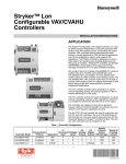
®
IntesisBox KNX
LON
User's Manual
v10 r12 eng
IntesisBox® KNX - LON
© Intesis Software S.L.
User's manual v10 r12 eng
All Rights Reserved.
Information in this document is subject to change without notice. The software described in
this document is furnished under a license agreement or nondisclosure agreement. The
software may be used only in accordance with the terms of those agreements. No part of
this publication may be reproduced, stored in a retrieval system or transmitted in any form
or any means electronic or mechanical, including photocopying and recording for any
purpose other than the purchaser’s personal use without the written permission of Intesis
Software S.L.
Intesis Software S.L.
Milà i Fontanals, 1 bis - 1º
08700 Igualada
Spain
TRADEMARKS
All trademarks and tradenames used in this document are acknowledged to be the copyright of their respective holders.
Doc: IntesisBox KNX - LON v10 r12 eng.pdf
© Intesis Software S.L. - All rights reserved
IntesisBox is a registered trademark of Intesis Software SL
URL
email
tel
http://www.intesis.com
[email protected]
+34 938047134
Page 2 of 46
IntesisBox® KNX - LON
User's manual v10 r12 eng
Gateway for the integration of LonWorks devices
into KNX TP-1 (EIB) control systems.
Two models are available for this gateway, with the following Order Codes:
IBOX-KNX-LON-A
Basic model supporting up to 500 internal datapoints and up to 64 LON devices.
IBOX-KNX-LON-B
Extended model supporting up to 4000 internal datapoints and up to 128 LON devices.
Doc: IntesisBox KNX - LON v10 r12 eng.pdf
© Intesis Software S.L. - All rights reserved
IntesisBox is a registered trademark of Intesis Software SL
URL
email
tel
http://www.intesis.com
[email protected]
+34 938047134
Page 3 of 46
IntesisBox® KNX - LON
User's manual v10 r12 eng
INDEX
1.
Description ..................................................................................................... 5
1.1
Introduction ................................................................................................ 5
1.2
Functionality................................................................................................ 6
1.3
Capacity of IntesisBox .................................................................................. 7
2.
KNX System ................................................................................................... 8
2.1
Description .................................................................................................. 8
2.2
Points definition ........................................................................................... 9
3.
LON interface of IntesisBox............................................................................. 10
3.1
Description ................................................................................................ 10
3.2
Points definition ......................................................................................... 12
4.
LinkBoxEIB. Configuration & monitoring tool for intesisBox KNX series ................. 13
4.1
Introduction .............................................................................................. 13
4.2
Project definition ........................................................................................ 13
4.3
Connection configuration............................................................................. 18
4.4
Signals configuration .................................................................................. 21
4.4.1 Remember ............................................................................................. 25
4.4.2 Restrictions ............................................................................................ 25
4.5
Saving the configuration and sending it to IntesisBox ..................................... 26
4.6
Signals viewer ........................................................................................... 27
4.7
System commands ..................................................................................... 28
4.8
Files ......................................................................................................... 29
5.
Setup process and troubleshooting .................................................................. 30
5.1
Pre-requisites ............................................................................................ 30
5.2
Setup procedure ........................................................................................ 30
6.
Connections .................................................................................................. 33
7.
LON interface specifications ............................................................................ 35
7.1
Supported basic LON data types................................................................... 35
8.
Technical characteristics................................................................................. 36
9.
Dimensions................................................................................................... 37
10.
Annexes ....................................................................................................... 38
10.1
Integration of DAIKIN VRV air conditioning systems with KNX.......................... 38
10.1.1
Using LinkBoxEIB to configure and setup the integration .......................... 39
10.2
How to setup LonWorks’ device address in IntesisBox and how to declare
LonWorks devices as commissioned using LinkBoxEIB ............................................... 41
Doc: IntesisBox KNX - LON v10 r12 eng.pdf
© Intesis Software S.L. - All rights reserved
IntesisBox is a registered trademark of Intesis Software SL
URL
email
tel
http://www.intesis.com
[email protected]
+34 938047134
Page 4 of 46
IntesisBox® KNX - LON
User's manual v10 r12 eng
1. Description
1.1
Introduction
This document describes the integration of KNX TP-1 (EIB) systems LON (TP/FT-10)
compatible devices or systems using the gateway IntesisBox KNX - LON.
This document assumes that the user is familiar with KNX and LON technology and technical
terms.
From now on, and with the aim of easy the read of this document, just the word
"IntesisBox" will be used instead of the full gateway model description "IntesisBox KNX LON".
The aim of this integration is to make accessible signals and resources of any LON based
system or device (for example Daikin VRV AC system) from any KNX TP-1 (EIB) control
system.
For this, IntesisBox acts as a LON client device in its LON interface, reading/writing points of
other LON device(s), and offering this point's values of LON device(s) through its KNX
interface, acting in the KNX system as one more KNX device of the system. The readings of
the LON device(s) are performed by IntesisBox by continuous polling.
LON device
KNX
LON
TP-FT/10
EIB Bus
IntesisBox
LON device
LinkBoxEIB
Configuration
Software
RS232
Only needed for configuration
Integration of LON and KNX using
IntesisBox KNX - LON gateway
Doc: IntesisBox KNX - LON v10 r12 eng.pdf
© Intesis Software S.L. - All rights reserved
IntesisBox is a registered trademark of Intesis Software SL
URL
email
tel
http://www.intesis.com
[email protected]
+34 938047134
Page 5 of 46
IntesisBox® KNX - LON
1.2
User's manual v10 r12 eng
Functionality
The integration operation is as follow:
From the LON system point of view, after the start up process, IntesisBox reads
continuously the points configured to be read by polling into the LON devices, and updates
in its memory all the values received.
Every one of the mentioned points of the LON devices is associated to a KNX group address,
with this, all the LON system is seen as one more KNX device from the KNX system point of
view, with the same configuration and operation characteristics.
When a change in any point (of type output or input/output) in the LON device is detected
during the polling process, a write telegram is sent immediately to the KNX bus, of the
associated KNX Group, to inform the KNX system about the new value.
When a telegram is received from the KNX bus, of a KNX Group address associated to a
LON point, a message is sent immediately to the corresponding LON device to perform the
corresponding action.
In the continuous polling of the LON devices, if a non response of any LON device is
detected, the corresponding virtual signal inside IntesisBox will be activated indicating
communication error with that LON device. These virtual signals indicating communication
status in real time with the LON devices are also accessible from KNX, like the rest of the
points of IntesisBox. A special virtual signal indicating the correct operation of the LON
interface handler inside the IntesisBox is also available from KNX.
Doc: IntesisBox KNX - LON v10 r12 eng.pdf
© Intesis Software S.L. - All rights reserved
IntesisBox is a registered trademark of Intesis Software SL
URL
email
tel
http://www.intesis.com
[email protected]
+34 938047134
Page 6 of 46
IntesisBox® KNX - LON
1.3
User's manual v10 r12 eng
Capacity of IntesisBox
Element
Max.
Max.
(Basic (Extended
version) version)
Type of LON devices
Supported number of
network variable fields
500
Supported number of LON 64
devices
4000
128
Notes
Those supporting Twisted Pair - Free
Topology channel (TP/FT-10)
Maximum number of points (KNX group
addresses) that can be defined into
IntesisBox. Each of them can contain an
individual field from a network variable.
Maximum number of different LON
devices that can be defined into
IntesisBox (to read/write points into
them).
There are two different models of IntesisBox® KNX - LON with different capacity each one of
them.
•
•
Basic model, allowing to integrate up to 500 points and 64 devices.
Ref.: IBOX-KNX-LON-A
Extended model, allowing to integrate up to 4000 points and 128 devices.
Ref.: IBOX-KNX-LON-B
Doc: IntesisBox KNX - LON v10 r12 eng.pdf
© Intesis Software S.L. - All rights reserved
IntesisBox is a registered trademark of Intesis Software SL
URL
email
tel
http://www.intesis.com
[email protected]
+34 938047134
Page 7 of 46
IntesisBox® KNX - LON
User's manual v10 r12 eng
2. KNX System
In this section, a common description for all IntesisBox KNX series gateways is given, from
the point of view of KNX system which is called from now on internal system. The LON
system is also called from now on external system.
2.1
Description
IntesisBox KNX connects directly to the KNX TP-1 (EIB) bus and behaves as one more
devices into the KNX system, with the same configuration and operational characteristics as
other KNX devices.
Internally, the circuit part connected to the KNX bus is opto-isolated from the rest of the
electronics.
IntesisBox KNX receives, manages and sends all the telegrams related to its configuration
to the KNX bus.
On receiving telegrams of KNX Groups associated to the external system (LON in this case),
the corresponding messages are sent to the external system to maintain both systems
synchronised in every moment.
When a change in a signal of the external system is detected, a telegram is sent to the KNX
bus (of the associated KNX group) to maintain both systems synchronised in every moment.
The status of the KNX bus is checked continuously and, if a bus drop down is detected, due
to a failure in the bus power supply for example, when the KNX bus is restored again,
IntesisBox will retransmit the status of all the KNX groups marked as "T" Transmit. Also the
Updates of the groups marked as "U" Update will be performed. The behaviour of IntesisBox
for every point is determined by the flags configured individually per every point.
Doc: IntesisBox KNX - LON v10 r12 eng.pdf
© Intesis Software S.L. - All rights reserved
IntesisBox is a registered trademark of Intesis Software SL
URL
email
tel
http://www.intesis.com
[email protected]
+34 938047134
Page 8 of 46
IntesisBox® KNX - LON
2.2
User's manual v10 r12 eng
Points definition
Every signal of the external system (LON) to use has the following KNX properties:
Property
Description
Description
Signal's Description. Only for informative purposes, allows identifying the
signal comfortably.
EIS (DataPoint) It's the KNX data type used to code the signal's value. It will depend on the
type of signal associated in the external system in every case. In some
integration it is selectable, in others it is fixed due to the intrinsic
characteristics of the signal.
Group
It's the KNX group to which the signal is associated. It is also the group to
which the read (R), write (W), transmit (T) and update (U) flags are
applied. Is the sending group.
Listening
They are the addresses that will actuate on the signal, apart of the Group
addresses
address.
R
Read flag. If activated, read telegrams of this group will be allowed.
W
Write flag. If activated, write telegrams of this group will be allowed.
T
Transmit flag. If activated, when the signal's value changes, due to a
change in the external system, a write telegram of the group will be sent to
the KNX bus.
U
Update flag. If activated, on IntesisBox start-up or after a KNX bus reset
detection, read telegrams of the sending group will be sent to the KNX bus,
and the value received will be sent to the external system as if it has been
received by a write telegram.
Active
If activated, the signal will be active in IntesisBox, if not, the behaviour will
be as if the signal is not defined. Allows deactivating signals without the
need of delete them for possible future use.
These properties are common for all IntesisBox KNX series gateways, although for every
integration may have specific properties according to the type of signals of the external
system in every case.
Doc: IntesisBox KNX - LON v10 r12 eng.pdf
© Intesis Software S.L. - All rights reserved
IntesisBox is a registered trademark of Intesis Software SL
URL
email
tel
http://www.intesis.com
[email protected]
+34 938047134
Page 9 of 46
IntesisBox® KNX - LON
User's manual v10 r12 eng
3. LON interface of IntesisBox
3.1
Description
The LON systems are composed of devices connected to a network, the media and topology
of the bus used to interconnect the different devices in the network can be of some different
types, even devices connected to different media can coexist and communicate between
them in the same LON network by the use of media converters (switches, routers…).
IntesisBox LON interface is compatible with twisted pair free topology channel (TP/FT-10)
media, nowadays the most widely used media due to its robustness and the different
topologies that can be used and mixed together.
All LON devices offer their internal datapoints (of input and output type) in the form of
standardised data objects called Standard Network Variable Types (SNVTs), which assures
total interoperability between LON devices. More specific data types used basically for
configuration purposes of the LON devices are also defined by the standard (SCPTs), and
even user defined data types (UNVT) can be implemented and used by any manufacturer in
a LON device.
All the mentioned data types are also supported by IntesisBox.
Standard Network Variable Types (SNVTs) are named by convention with a prefix that
indicates if it is an input variable (prefix nvi) or an output variable (prefix nvo).
A SNVT can be composed of one or more data fields, for example, one of the most used
SNVTs is the type switching, this SNVT has two data fields: value, and state.
Many devices use this SNVT switching for basic ON/OFF operations, and for the device to
accept a given operation (ON or OFF) you must write specific values in the field state but
also in the field value at the same time. For example, when communicating with the Daikin
LON interface DMS504B51, to switch ON the AC indoor unit number 1, you have to use the
variable nviOnOff_01 (of type switching), and the values to write in both fields can be the
following:
Operation
ON
OFF
OFF
Value
1 - 255
0
Any (0 - 255)
State
1
1
0
Note that you must write into both fields of the variable to accomplish both operations, ON
and OFF. This can be a great inconvenience to be done from systems like KNX in which just
an object of type switching (one single value is sent) is used for this kind of operations.
To solve this, special SNVT with filters have been incorporated to IntesisBox, using these
special SNVTs with filters you can write into more than one field of the LON variable when
you write just a single value from KNX. See below an example of use of a special SNVT with
filter called SNVT_switch_filter_0_1 linked to the mentioned above variable nviOnOff_01 of
Daikin.
Doc: IntesisBox KNX - LON v10 r12 eng.pdf
© Intesis Software S.L. - All rights reserved
IntesisBox is a registered trademark of Intesis Software SL
URL
email
tel
http://www.intesis.com
[email protected]
+34 938047134
Page 10 of 46
IntesisBox® KNX - LON
User's manual v10 r12 eng
Operation
KNX
SNVT_switch_filter_0_1
nviOnOff_0_1
Value
nviOnOff_0_1
State
OFF
ON
0
1
0
1
0
100
0
1
This way you only have to choose the right special SNVT with filter into the IntesisBox
configuration table for this kind of LON variable and associate it to an individual KNX group
address (of an standard EIS type).
See below in this document the list of special SNVTs with filters available in IntesisBox.
Doc: IntesisBox KNX - LON v10 r12 eng.pdf
© Intesis Software S.L. - All rights reserved
IntesisBox is a registered trademark of Intesis Software SL
URL
email
tel
http://www.intesis.com
[email protected]
+34 938047134
Page 11 of 46
IntesisBox® KNX - LON
3.2
User's manual v10 r12 eng
Points definition
Every point defined into IntesisBox has the following LON features associated to it:
Feature
Device
Description
LON device to which belongs the point, from a list of LON devices that
can be defined into IntesisBox (up to 128).
For each LON device defined, a virtual signal is created automatically in
IntesisBox to inform about the communication with the LON device,
this signal is available also from the KNX interface like the rest of the
points.
SNVT
SNVT Name
Idx
RW
SNVT number according to EIA-709 standard.
SNVT Name, selectable from the list of all available SNVTs defined by
EIA-709 standard, and also special SNVTs with filters explained above.
Index of the network variable inside the LON device.
Indicates if the variable is of type input (W), output (R), or
input/output (RW).
Note that an output variable in the LON device must be defined as R, to be read by the
IntesisBox. And an input variable as W, to be written by the IntesisBox.
Doc: IntesisBox KNX - LON v10 r12 eng.pdf
© Intesis Software S.L. - All rights reserved
IntesisBox is a registered trademark of Intesis Software SL
URL
email
tel
http://www.intesis.com
[email protected]
+34 938047134
Page 12 of 46
IntesisBox® KNX - LON
User's manual v10 r12 eng
4. LinkBoxEIB. Configuration & monitoring tool for intesisBox KNX
series
4.1
Introduction
LinkBoxEIB is a Windows compatible software tool developed specifically to monitor and
configure IntesisBox KNX series gateways. It is possible to configure all external protocols
available for IntesisBox KNX and to maintain different customer’s configurations based on a
LinkBoxEIB project for every different installation. Maintaining always on hard disk a copy of
the last configuration files for every external protocol and customer, that is to say for every
project.
From LinkBoxEIB, as well as configure the integration signals list and connection parameters
for every external protocol, it is permitted also to select the serial port to use to connect to
IntesisBox and the use of some tools for monitoring and debugging de device. Some of
these tools will be explained in this document but only some of them, the rest of available
debugging tools and commands will not be explained here because they are for exclusive
use under the recommendations of Intesis Software technical support.
LinkBoxEIB allows configuring all IntesisBox KNX series independently of the external
system or protocol used. For every external system, LinkBoxEIB has a specific configuration
window. Periodically, new free versions of LinkBoxEIB are released incorporating the latest
developed integrations for external systems.
4.2
Project definition
The first step to do in LinkBoxEIB for a new installation is to create the installation’s project
giving a descriptive name to it. When you create a project, a new folder is created with the
name of the project containing the configuration files needed depending on the external
protocol selected for the project. It is strongly recommended that you create a new project
for every installation, if not, overwriting of configuration files of previous installations using
the same external protocol may occur, loosing the configuration data for those previous
installations. The projects folder is located in AppFolder\ProjectsEIB, where AppFolder is the
installation folder of LinkBoxEIB (by default C:\Program Files\Intesis\LinkBoxEIB). Inside
the projects folder, a new folder will be created for every project defined in LinkBoxEIB with
the files needed for the project.
When you open LinkBoxEIB, the project selection window will appear inviting you to select a
project or to create a new one. A demo project for every external protocol supported is
provided with the standard installation of LinkBoxEIB.
You can create a brand new project, which will create a blank project (only basic
parameters will be already configured), or you can select a demo project based on the
external protocol desired and create a new project based on this demo project selected (all
the configuration of the demo project will be copied into the new project created).
Doc: IntesisBox KNX - LON v10 r12 eng.pdf
© Intesis Software S.L. - All rights reserved
IntesisBox is a registered trademark of Intesis Software SL
URL
email
tel
http://www.intesis.com
[email protected]
+34 938047134
Page 13 of 46
IntesisBox® KNX - LON
User's manual v10 r12 eng
Project selection window
To create a new project, select a project using the same external protocol you want to use
in the new project and push New button. You will be prompted to create a copy of the
selected project (useful for similar installations) or create a brand new one.
If you select Yes, you will be prompted to specify a name and a description for the new
project that will contain a copy of the configuration of the selected one.
If you select No, you can specify a name, a description and an external protocol to use from
the list of available external protocols. This will create a brand new project based in the
external protocol specified.
Doc: IntesisBox KNX - LON v10 r12 eng.pdf
© Intesis Software S.L. - All rights reserved
IntesisBox is a registered trademark of Intesis Software SL
URL
email
tel
http://www.intesis.com
[email protected]
+34 938047134
Page 14 of 46
IntesisBox® KNX - LON
User's manual v10 r12 eng
On Accept, a new folder will be created inside the projects folder with the name given to the
project, this folder will contain the template configuration files if the project is a brand new
one, or a copy of the configuration files if it is a copy of a selected one.
A description of the files created for a LON protocol based project can be found in section
Files below in this document.
From all the possibilities of LinkBoxEIB, only changes in configuration for the integration and
configuration file generation can be performed while disconnected from IntesisBox (working
off-line), allowing you to do these tasks in the office more comfortably. Before any
monitoring or downloading action to IntesisBox can be performed, the connection between
IntesisBox and the PC running LinkBoxEIB must be established (working on-line). To do so
follow these steps:
1. Make sure IntesisBox is powered-up a correctly connected to the KNX system via the
EIB bus and to the LON system via the LON Bus connection (Consult details for
connection and pin assignments in section Connections of this document).
2. Connect a free PC serial port to IntesisBox's serial port marked as PC Console. (Use the
standard serial cable supplied with IntesisBox or make your own cable following the pin
assignments specified in section Connections in this document).
3. Select in LinkBoxEIB the PC serial port used for the connection to IntesisBox. Use menu
Configuration -> Connection.
4. Check the checkbox off-line under the menu bar (it will change automatically to on-line)
and LinkBoxEIB will ask for INFO about the IntesisBox connected to it via the serial
connection, if the connection is ok then IntesisBox will respond with its identification
(this can be monitored in the IntesisBox Communication Console window, as showed
below).
Doc: IntesisBox KNX - LON v10 r12 eng.pdf
© Intesis Software S.L. - All rights reserved
IntesisBox is a registered trademark of Intesis Software SL
URL
email
tel
http://www.intesis.com
[email protected]
+34 938047134
Page 15 of 46
IntesisBox® KNX - LON
User's manual v10 r12 eng
Once connected to the IntesisBox, all the options of LinkBoxEIB are fully operative.
To monitor the communication between IntesisBox and the KNX system, select the menu
View -> Bus -> EIB. The EIB communication Viewer window will be opened. This window
shows in real time all the communication frames between IntesisBox and the KNX system as
well as debugging messages referent to the internal protocol (KNX) sent by IntesisBox.
Doc: IntesisBox KNX - LON v10 r12 eng.pdf
© Intesis Software S.L. - All rights reserved
IntesisBox is a registered trademark of Intesis Software SL
URL
email
tel
http://www.intesis.com
[email protected]
+34 938047134
Page 16 of 46
IntesisBox® KNX - LON
User's manual v10 r12 eng
To monitor the communication between IntesisBox and the external system (LON in this
case), select the menu View -> Bus -> External system. The External protocol
communication viewer window will be opened. This window shows in real time all the
communication frames between IntesisBox and the LON devices as well as debugging
messages referent to external protocol (LON) sent by IntesisBox.
Doc: IntesisBox KNX - LON v10 r12 eng.pdf
© Intesis Software S.L. - All rights reserved
IntesisBox is a registered trademark of Intesis Software SL
URL
email
tel
http://www.intesis.com
[email protected]
+34 938047134
Page 17 of 46
IntesisBox® KNX - LON
User's manual v10 r12 eng
To configure the integration connection parameters, and the points list, select menu
Configuration -> IntesisBox. The LON Configuration window will be opened.
4.3
Connection configuration
Select the Connection tab to configure the connection parameters.
Two kinds of information are configured using this window, the parameters of the KNX
interface, and the parameters of the LON interface.
KNX interface configuration parameters:
1
2
3
KNX configuration
1. Enter the physical address desired for IntesisBox inside the KNX network.
2. Check this if you want IntesisBox to force the readings in KNX of those points configured
with "U" or "U2" flag after a KNX bus reset detection.
3. Delay (in seconds) to wait before perform the readings in KNX of those points configured
with "U" or "U2" flag after a KNX bus reset detection (configure it at least to 4 seconds
to allow all the devices in the KNX bus to start-up correctly after a bus power failure).
Doc: IntesisBox KNX - LON v10 r12 eng.pdf
© Intesis Software S.L. - All rights reserved
IntesisBox is a registered trademark of Intesis Software SL
URL
email
tel
http://www.intesis.com
[email protected]
+34 938047134
Page 18 of 46
IntesisBox® KNX - LON
User's manual v10 r12 eng
LON interface configuration parameters:
1
2
3
4
5
1. Enter the Domain number for IntesisBox into the LON network.
2. Enter the length in bytes of the Domain field.
3. Enter the Subnet number for IntesisBox into the LON network.
4. Enter the Node number for IntesisBox into the LON network.
5. Select the version of IntesisBox used.
Remember you can identify the version used by the order code printed in the front label
of IntesisBox:
•
•
IBOX-KNX-LON-A. Basic model supporting up to 64 LON devices and 500 points.
IBOX-KNX-LON-B. Extended model supporting up to 64 LON devices and 4000
points.
You can identify also the model of IntesisBox by its identification given in response to an
INFO command, it is something like this:
IntesisBox_EIB_LON-A… -> this is the basic model.
IntesisBox_EIB_LON-B… -> this is the extended model.
Doc: IntesisBox KNX - LON v10 r12 eng.pdf
© Intesis Software S.L. - All rights reserved
IntesisBox is a registered trademark of Intesis Software SL
URL
email
tel
http://www.intesis.com
[email protected]
+34 938047134
Page 19 of 46
IntesisBox® KNX - LON
User's manual v10 r12 eng
8
7
9
10
6
12
11
6. Use this button to define the number of LON devices to integrate. Remember the
limitations: just 64 devices in IntesisBox basic model, and 128 devices in IntesisBox
extended model.
7. List of LON devices to integrate. Check the devices you want to activate. Select a device
to configure its properties.
For every LON device defined, these are the properties that must be entered:
8. Enter the Neuron Id, or
9. Enter the Subnet and Node number of the LON device.
10. Enter the device name (optional, just for identification purposes).
11. Enter the type of addressing to use by IntesisBox to access the device: Neuron Id or
Subnet/Node. If the devices are in an already commissioned LON network, then choose
Subnet/Node here and enter the correct Subnet and Node numbers of the devices (this
must be supplied by the LON integrator that has commissioned the network). If the
devices are not commissioned, then choose Neuron Id here and enter the correct
Neuron Id numbers of the devices. IntesisBox has embedded tools to scan and detect
Neuron Id numbers of the LON devices connected to the network, and also to declare
the devices as commissioned, avoiding this way the need of a commissioning tool like
LonMaker. See details of use of these embedded tools below in this document.
12. Device's polling cycle time period.
Doc: IntesisBox KNX - LON v10 r12 eng.pdf
© Intesis Software S.L. - All rights reserved
IntesisBox is a registered trademark of Intesis Software SL
URL
email
tel
http://www.intesis.com
[email protected]
+34 938047134
Page 20 of 46
IntesisBox® KNX - LON
4.4
User's manual v10 r12 eng
Signals configuration
Select the Signals tab to configure the signals list (the IntesisBox's internal datapoints).
1
2
3
4
5
6
18
7
8
Signals list
9
10 11
17
12
13
14
15
16
1. #. Signal’s number (edit not permitted). Every row in the grid corresponds to a signal
(point). Signals (rows in the grid) can be added or deleted selecting the desired row and
clicking Add or Delete buttons. Deletion action can be executed for a single row or even
for some consecutive rows, all the rows selected will be deleted. This column is used
only to enumerate the rows in the grid (signals).
2. Dev. Device number to which belongs the point. Referenced to the list of devices defined
in Connection Tab. Note that this is the order number of the device (from top to bottom)
in the devices list.
3. SNVT. SNVT Id number according to EIA-709 standard. Edit not permitted.
The Communication error virtual signals have always a predefined special SNVT Id
numbers -1 and -2.
4. SNVT Name. This is the SNVT to select for the point. Select the SNVT desired from a list
of all standard SNVTs defined by LonMark International and a few special SNVTs with
filter (their use explained in section 3.1), open this list by clicking the mouse right
button over the column. Consult the documentation of the LON devices to integrate for
details of which SNVT is used for every point into the device.
5. Idx. This is the index of the variable inside the LON device. Consult the device's
documentation to obtain it.
6. RW. Indicates if the variable is of type input (W), output (R), or input/output (RW).
Note that an output variable in the LON device must be defined as R, to be read by the IntesisBox. And an
input variable must be defined as W, to be written by the IntesisBox.
7. Description. Signal’s description. Used to describe the signal at user level.
Doc: IntesisBox KNX - LON v10 r12 eng.pdf
© Intesis Software S.L. - All rights reserved
IntesisBox is a registered trademark of Intesis Software SL
URL
email
tel
http://www.intesis.com
[email protected]
+34 938047134
Page 21 of 46
IntesisBox® KNX - LON
User's manual v10 r12 eng
8. EIS. KNX data type (Data point) to encode the signal’s value. Possible values are:
switching (1 bit), dimming (4 bit), float (16 bit), scaling (8 bit), drive control (1 bit),
priority (2 bit), float IEEE (32 bit), counter (8 bit), counter (16 bit), counter (32 bit),
ASCII char (8 bit). Edit using the mouse right-button-click menu available on the
column.
9. Group. Main EIB group address for the signal. Format: P/I/S or P/S. Flags R,W,T,U
explained below will only apply for this main EIB group address, not for listening
addresses (if defined). It is the sending group address.
10. Listening addresses. EIB group addresses that will be listen by IntesisBox for this signal,
that is to say, if IntesisBox receives an EIB telegram with destination one of these
listening addresses, then the telegram will be taken into account and the corresponding
action will be performed on this signal. Format: P/I/S or P/S, if more than one is entered
then they must be separated by comma.
11. R. Indicates if this signal is allowed to be read from KNX system. Possible values: “R” or
blank. “R” means flag activated. This cell is automatically filled according to value
selected in the cell RW.
12. W. Indicates if this signal is allowed to be written from KNX system. Possible values:
“W” or blank. “W” means flag activated. This cell is automatically filled according to
value selected in the cell RW.
13. T. Indicates if this signal will generate a telegram sending to the KNX system following a
change of the signal’s value, that is to say, any change of value of this signal in LON
side will be transmitted to the KNX system if this flag is activated. Possible values: “T” or
blank. “T” means flag activated. This cell is automatically filled according to value
selected in the cell RW.
14. U. Indicates if this signal will be updated whenever IntesisBox starts up or after an EIB
bus reset. “U” means flag activated for the main EIB group address (a read of the main
EIB group address will be performed in the KNX system for the update). “U2” means flag
activated for the first listening address defined (a read of the first listening address
defined for the point will be performed in the KNX system for the update). Blank means
flag not activated. Edit using the mouse right-button-click pop-up menu available on the
column. Configurable only for input LON variables (W).
15. Active. Indicates if the signal is active or not for the integration. Possible values: 0-No,
1-Yes. Edit using the mouse right-button-click menu available on the column.
16. Buttons to move the selected row (or rows) up or down inside the grid. To move up or
down inside the grid a single row or a group of consecutive rows, just select the row or
rows using the left button of the mouse and push the desired up or down button. (This
can be done also using the key combinations ALT+arrow up or ALT+arrow down instead
of up or down buttons).
Doc: IntesisBox KNX - LON v10 r12 eng.pdf
© Intesis Software S.L. - All rights reserved
IntesisBox is a registered trademark of Intesis Software SL
URL
email
tel
http://www.intesis.com
[email protected]
+34 938047134
Page 22 of 46
IntesisBox® KNX - LON
User's manual v10 r12 eng
Useful tips for a more quick and comfortable use and configuration of the signals table:
The columns SNVT Name, RW, EIS, U and Active can be modified selecting one or just more
than one consecutive cells in the same column and using the contextual menu appearing
with mouse right button click over the cells selected.
The columns U and Active can be also modified using mouse-left-button double-click over
the desired cell.
In column Dev you can enter the desired value individually per cell or you can auto
enumerate some consecutive cells, for this last follow these steps:
1. Select using the left mouse button (clicking and dragging) the Dev field of all the
rows in the list to which you want to automatically assign values (must be
consecutive rows).
2. Click right mouse button over the selected fields and select Auto Enumeration option
from the pop-up menu that will appear.
3. Enter the first value to assign.
Doc: IntesisBox KNX - LON v10 r12 eng.pdf
© Intesis Software S.L. - All rights reserved
IntesisBox is a registered trademark of Intesis Software SL
URL
email
tel
http://www.intesis.com
[email protected]
+34 938047134
Page 23 of 46
IntesisBox® KNX - LON
User's manual v10 r12 eng
4. Enter the increment between consecutive assignments. For example selecting 0 for
the first value and an increment of 1, the values generated will be 0,1,2,3,4.. and so
on. To assign the same value to all the rows (useful to assign the same Device
number in the column Dev for some consecutive rows) just select the desired value
and an increment of 0.
Doc: IntesisBox KNX - LON v10 r12 eng.pdf
© Intesis Software S.L. - All rights reserved
IntesisBox is a registered trademark of Intesis Software SL
URL
email
tel
http://www.intesis.com
[email protected]
+34 938047134
Page 24 of 46
IntesisBox® KNX - LON
User's manual v10 r12 eng
4.4.1 Remember
If "T" is not activated, the changes in the external system (BACnet) will not be
transmitted to the KNX.
If "R" is not activated, the KNX group address could not be read by Read Requests from
KNX.
If "W" is not activated, no write on the group address could be done from KNX, neither
on the links (listening addresses).
If "U" is activated, after IntesisBox start-up or a KNX bus reset, READ Requests will be
sent to KNX to update the sending group.
The groups defined as just links, will take the EIS of the first linked group.
The data of the groups read from KNX due to read requests between other KNX devices,
will be treated as writes on the groups (standard behaviour BCU1).
Automatic type conversion is performed by IntesisBox, for example if an EIS5 is
received by a group of type EIS1, then it is performed the conversion EIS1=(EIS5<>0),
or EIS5=EIS9 and EIS9=EIS5, EIS6=EIS5(0..255), etc.
It is recommended that listening addresses associated to different groups maintain the
same EIS in all the groups, if not, none desired conversions can be performed.
A write from KNX is propagated to the external system through the group address and
also through the listening addresses.
A write from the external system is NOT propagated to KNX through the listening
addresses, but DO update the local sending groups that are used as listening addresses.
If a sending group is used as listening address with other local sending groups, a write
from the external system will update the sending group but not the listening addresses.
4.4.2 Restrictions
It is allowed group numbers in format P/I/S, P/S or directly the group number coded.
It is not allowed duplicated sending groups (column Group).
Group 0 is not allowed, it is used for signals without sending group.
NO signal is allowed with none of R-W-T-U flags activated.
Empty groups are allowed, but only if they have just W activated and one or more
listening addresses.
Duplicated groups in the same listening address field are not allowed.
It is not allowed a listening address that is the same as the sending group (circular
reference).
Listening addresses are not allowed if the flag W is not activated. Without W activated,
the listening addresses would not work.
Only those EIS defined are allowed.
Doc: IntesisBox KNX - LON v10 r12 eng.pdf
© Intesis Software S.L. - All rights reserved
IntesisBox is a registered trademark of Intesis Software SL
URL
email
tel
http://www.intesis.com
[email protected]
+34 938047134
Page 25 of 46
IntesisBox® KNX - LON
4.5
User's manual v10 r12 eng
Saving the configuration and sending it to IntesisBox
When the configuration is finished, click on button Save to save it to the project folder on
hard disk. You will be prompted to generate the configuration file to send to IntesisBox, if
you select Yes, the binary file containing the configuration for IntesisBox will be generated
and saved also into the project folder.
Once the configuration has been saved and the configuration file for IntesisBox has been
generated, to send this configuration file to IntesisBox, click on the button Send File. The
process of file transmission can be monitored in the IntesisBox Communication Console
window. If the file transmission is ok, IntesisBox will reboot automatically with the new
configuration loaded.
Doc: IntesisBox KNX - LON v10 r12 eng.pdf
© Intesis Software S.L. - All rights reserved
IntesisBox is a registered trademark of Intesis Software SL
URL
email
tel
http://www.intesis.com
[email protected]
+34 938047134
Page 26 of 46
IntesisBox® KNX - LON
4.6
User's manual v10 r12 eng
Signals viewer
Once IntesisBox is running with the correct configuration, to supervise the status of the
configured signals, select menu View -> Signals. The Signals Viewer window will be opened.
This window shows all the active IntesisBox's signals with its main configuration parameters
and its real time value in the column Value. After a reset of IntesisBox or after sending a
configuration file to the IntesisBox, all the signal's values will be updated automatically in
the signals viewer, in case you connect to the IntesisBox when it is already running, you
should press the Update button to get updated values, press just once the button to update
all the signal values, from this moment the signal values will be maintained updated until
the connection is closed.
The signals viewer can be used although only one system is connected to the IntesisBox,
KNX or LON, and is very useful for supervision and test.
It is possible to force a specific value to any signal for test purposes, to do so just double
click on the row and select the desired value and Accept in the Data Test window. If the
signal has W-T activated, its value will be updated and a telegram will be sent to KNX
indicating the new value, the same way as if it has been received from LON system. If the
signal has W activated, the new value entered will be sent to the external system, LON in
this case, the same way as if it has been received from KNX.
Doc: IntesisBox KNX - LON v10 r12 eng.pdf
© Intesis Software S.L. - All rights reserved
IntesisBox is a registered trademark of Intesis Software SL
URL
email
tel
http://www.intesis.com
[email protected]
+34 938047134
Page 27 of 46
IntesisBox® KNX - LON
User's manual v10 r12 eng
This tool is very useful to test any of the systems connected to the IntesisBox, KNX and
LON without the need to actuate on the real signals.
The signals viewer window has a button to copy to the Windows Clipboard all the contents
of the window (in tab separated text format).
4.7
System commands
LinkBoxEIB includes an option to send to IntesisBox a set of system commands for
debugging and control purposes; this list is available in the commands list as shown in the
figure below. To send a command to IntesisBox just select it from the list, or type it with
the correct format, and press Enter or click on button Send. IntesisBox will act accordingly
with the command received; the process can be monitored in the IntesisBox Communication
Console window. The use of some of these commands can be critical for IntesisBox normal
operation, having this in mind use only these commands following the recommendations of
Intesis Software technical support. A list of the more commonly used commands and the
way to use them will be returned by IntesisBox after sending the HELP command.
Doc: IntesisBox KNX - LON v10 r12 eng.pdf
© Intesis Software S.L. - All rights reserved
IntesisBox is a registered trademark of Intesis Software SL
URL
email
tel
http://www.intesis.com
[email protected]
+34 938047134
Page 28 of 46
IntesisBox® KNX - LON
4.8
User's manual v10 r12 eng
Files
LinkBoxEIB saves IntesisBox configuration in the following files inside the project folder:
PROJECT.INI
LON.INI
LON.DAT
LON.SNVT
LON.LBOX
Ini file containing general information referent to the project
Ini file containing the information referent to the connection
window and other special adjustments
Text file (tab separated values) with the signals information
(signals list). This file can be edited (with Excel for example) to
change the configuration quicker and easier. Later on, when
selecting Configuration -> IntesisBox in LinkBoxEIB, if the changes
have been made respecting the correct format, all the changes in
the configuration done from Excel can be seen in the signals list.
File containing the SNVTs used in the project, the standard and the
specific ones.
Binary file created from the information in the files described
above. This is the file really uploaded to IntesisBox.
It is strongly recommended to back up the project folder containing these files in external
media, once the installation process is finished. This way you will be able to do future
configuration changes in case of reinstallation of LinkBoxEIB due, for example, to a failure
of the hard disk in the PC where LinkBoxEIB was previously installed.
The configuration cannot be downloaded from IntesisBox to LinkBoxEIB, only can
be uploaded; the upload file LON.LBOX does not contain all the integration
information, as for example the signals description.
Doc: IntesisBox KNX - LON v10 r12 eng.pdf
© Intesis Software S.L. - All rights reserved
IntesisBox is a registered trademark of Intesis Software SL
URL
email
tel
http://www.intesis.com
[email protected]
+34 938047134
Page 29 of 46
IntesisBox® KNX - LON
User's manual v10 r12 eng
5. Setup process and troubleshooting
5.1
Pre-requisites
It is necessary to have a KNX TP-1 (EIB) system operative and ready to be connected to the
KNX port of IntesisBox.
It is necessary to have the LON network connection beside IntesisBox with all LON devices
connected to this network.
Connectors, connection cables, PC for LinkBoxEIB, and network hub or switch are not
supplied by Intesis Software for this standard integration. The items supplied by Intesis
Software for this integration are:
•
•
•
•
5.2
IntesisBox KNX gateway with KNX internal protocol and LON external protocol firmware
loaded.
Console cable. Standard DB9F-DB9M cable 1.8 meters long.
LinkBoxEIB software.
Product documentation.
Setup procedure
1. Install LinkBoxEIB on your laptop.
2. Install IntesisBox in the desired installation site. The mounting can be on DIN rail or
on a stable not vibrating surface (DIN rail mounting inside a metallic industrial
cabinet connected to ground is recommended).
3. Connect the KNX TP-1 (EIB) bus cable to the port marked as KNX TP-1 (EIB) of
IntesisBox. (See details for this bus cable in section Connections of this document).
4. Connect the LON bus cable coming from the LON network to the port marked as
LON of IntesisBox. (See details for this communication cable in section Connections
of this document).
5. Power up IntesisBox using a standard power supply 220/125VAC-12VDC/300mA for
example.
WARNING! In order to avoid earth loops that can damage IntesisBox and/or any
other equipment connected to it, we strongly recommend:
•
•
The use of DC power supplies, floating or with the negative terminal connected to
earth. Never use a DC power supply with the positive terminal connected
to earth.
The use of AC power supplies only if they are floating and not powering any other
device.
6. Connect the communication cable coming from the serial port of your laptop PC to
the port marked as PC Console of IntesisBox. (See details for this communication
cable in section Connections of this document).
7. Open LinkBoxEIB, create a new project selecting a copy of the one named DEMO
LON and give it the name desired, select the serial port used to connect to
Doc: IntesisBox KNX - LON v10 r12 eng.pdf
© Intesis Software S.L. - All rights reserved
IntesisBox is a registered trademark of Intesis Software SL
URL
email
tel
http://www.intesis.com
[email protected]
+34 938047134
Page 30 of 46
IntesisBox® KNX - LON
User's manual v10 r12 eng
IntesisBox (menu Configuration -> Connection) and switch working mode to on-line
(checkbox off-line/on-line). The IntesisBox identification must appear in the
IntesisBox communication console window as showed below.
8. Open the EIB Communication Viewer window (menu View -> Bus -> EIB) and check
that there is communication activity, some TX frames and some other rx frames.
This means that the communication with the KNX system is ok. In case there is no
communication activity between IntesisBox and the KNX system check that KNX bus
is operative and well connected to the IntesisBox.
9. Open the External Protocol Communication Viewer window (menu View -> Bus ->
External system) and check that there is communication activity, some TX frames
and some other rx frames as showed in the figure below. This means that the
communication with the LON devices is ok.
Doc: IntesisBox KNX - LON v10 r12 eng.pdf
© Intesis Software S.L. - All rights reserved
IntesisBox is a registered trademark of Intesis Software SL
URL
email
tel
http://www.intesis.com
[email protected]
+34 938047134
Page 31 of 46
IntesisBox® KNX - LON
User's manual v10 r12 eng
In case there is no response from the LON devices to the frames sent by IntesisBox,
check that they are operative and reachable from the network connection used by
IntesisBox. See details for the communication cable between IntesisBox and LON
devices in section Connections of this document.
Doc: IntesisBox KNX - LON v10 r12 eng.pdf
© Intesis Software S.L. - All rights reserved
IntesisBox is a registered trademark of Intesis Software SL
URL
email
tel
http://www.intesis.com
[email protected]
+34 938047134
Page 32 of 46
IntesisBox® KNX - LON
User's manual v10 r12 eng
6. Connections
Power
KNX TP-1
(Bus EIB)
See technical
characteristics
-
+
+
-
CMN 24Vac
9 a 30Vdc 1,4W
24Vac 1,4VA
KNX TP-1
®
IntesisBox
www.intesis.com
LON TP/FT-10
B
A
PC Console
LinkBoxEIB
Only for configuration
LON
TP/FT-10
Console Cable 1.8 m.
Standard DB9F - DB9M.
Supplied.
IntesisBox
(Terminal
block 2C)
Cable
KNX TP-1 (EIB) Connection
EIB bus
+
-
IntesisBox
(Terminal
block 2C)
Cable
+
-
LON TP/FT-10 Connection
LON bus
A
B
A
B
Doc: IntesisBox KNX - LON v10 r12 eng.pdf
© Intesis Software S.L. - All rights reserved
IntesisBox is a registered trademark of Intesis Software SL
URL
email
tel
http://www.intesis.com
[email protected]
+34 938047134
Page 33 of 46
IntesisBox® KNX - LON
IntesisBox
(DB9 F)
Cable
(DB9 M)
TX
RX
GND
PC
Console
User's manual v10 r12 eng
PC (LinkBoxEIB) Connection
RS-232
(Straight)
2
3
5
2
3
5
PC
(DB9 M)
Cable
(DB9 F)
RX
TX
GND
Doc: IntesisBox KNX - LON v10 r12 eng.pdf
© Intesis Software S.L. - All rights reserved
IntesisBox is a registered trademark of Intesis Software SL
URL
email
tel
http://www.intesis.com
[email protected]
+34 938047134
Page 34 of 46
IntesisBox® KNX - LON
User's manual v10 r12 eng
7. LON interface specifications
LON supported channel: Free Topology (FT-10).
Configurable addressing options (on a ‘per device’ basis):
Subnet / node
Neuron-Id
Network variable sample rate:
Below 60ms per network variable (each network variable may contain several fields,
which will be mapped to different KNX points, if needed).
Supported network variable types:
All standard network variable types published by LonMark International are directly
supported by configuration tool, LinkBoxEIB.
Support for user-defined network variable types can be added in each case, by
entering their definition in LinkBoxEIB. In this case, following information needs to
be provided:
Scale factors: a, b and c
Number of fields
Basic LON data type of each field
7.1
Supported basic LON data types
Basic LON data type
Signed short
Unsigned short
Enum
Signed long
Unsigned long
Signed quad
Unsigned quad
Float
Bitfield
Description
8-bit signed data
8-bit unsigned data
8-bit unsigned data
16-bit signed data
16-bit unsigned data
32-bit signed data
32-bit unsigned data
32-bit IEEE float
1 to 8-bit length unsigned bitfield
Doc: IntesisBox KNX - LON v10 r12 eng.pdf
© Intesis Software S.L. - All rights reserved
IntesisBox is a registered trademark of Intesis Software SL
URL
email
tel
http://www.intesis.com
[email protected]
+34 938047134
Page 35 of 46
IntesisBox® KNX - LON
User's manual v10 r12 eng
8. Technical characteristics
Enclosure
Colour
Power
Mounting
LON port
KNX port
LED indicators
Push buttons
Console port
Configuration
Firmware
Operational
temperature
Operational humidity
Protection
RoHS conformity
Certifications
Plastic, type PC (UL 94 V-0). Dimensions: 107mm x 105mm x
58mm.
Light Grey. RAL 7035.
9 to 30Vdc +/-10% 1.4W.
24Vac +/-10% 1.4VA.
Plug-in terminal block for power connection (2 poles).
Surface.
Wall.
DIN rail EN60715 TH35.
1 x LON (TP-FT/10). Plug-in terminal block (2 poles).
1 x KNX TP1 (EIB) port opto-isolated. Plug-in terminal block (2
poles).
1 x Power.
2 x KNX port activity (Tx, Rx).
2 x LON port activity (Tx, Rx).
1 x KNX programming/bus.1
1 x LON service led.1
1 x KNX programming.1
1 x LON service switch.1
RS232. DB9 female connector (DCE).
Via console port.2
Allows upgrades via console port.
-25°C to +70°C
25-90% at 50ºC, non condensing
IP20 (IEC60529).
Compliant with RoHS directive (2002/95/CE).
CE
1
Not operational for the moment. Reserved for future use.
2
Standard cable DB9male-DB9female 1,8 meters long is supplied with the device for connection to a PC COM port for
configuring and monitoring the device. The configuration software, compatible with Windows® operating systems, is also
supplied.
Doc: IntesisBox KNX - LON v10 r12 eng.pdf
© Intesis Software S.L. - All rights reserved
IntesisBox is a registered trademark of Intesis Software SL
URL
email
tel
http://www.intesis.com
[email protected]
+34 938047134
Page 36 of 46
IntesisBox® KNX - LON
User's manual v10 r12 eng
9. Dimensions
Power
KNX
port
LON
port
Console
port
58 mm
107 mm
105 mm
Recommended available space for its installation into a cabinet (wall or DIN rail mounting),
with space enough for external connections:
100 mm
130 mm
115 mm
Doc: IntesisBox KNX - LON v10 r12 eng.pdf
© Intesis Software S.L. - All rights reserved
IntesisBox is a registered trademark of Intesis Software SL
URL
email
tel
http://www.intesis.com
[email protected]
+34 938047134
Page 37 of 46
IntesisBox® KNX - LON
User's manual v10 r12 eng
10. Annexes
10.1 Integration of DAIKIN VRV air conditioning systems with KNX
One of the main applications of IntesisBox KNX - LON is the integration of Daikin VRV air
conditioning systems with KNX building control systems.
For this application, Daikin VRV Air Conditioning system must be equipped with Daikin LON
gateway (model DMS504B51), this Daikin gateway is normally commissioned by Daikin
technical personnel, contact your nearest Daikin distributor for details.
……
Indoor units
Outdoor
units
DIII-NET
DMS504B51
EIB
LON
Free Topology
(FT-10) network
®
IntesisBox
KNX - LON
Doc: IntesisBox KNX - LON v10 r12 eng.pdf
© Intesis Software S.L. - All rights reserved
IntesisBox is a registered trademark of Intesis Software SL
URL
email
tel
http://www.intesis.com
[email protected]
+34 938047134
Page 38 of 46
IntesisBox® KNX - LON
User's manual v10 r12 eng
10.1.1 Using LinkBoxEIB to configure and setup the integration
The DMS504B51 LON gateway from Daikin allows to monitor / control up to 64 VRV indoor
units. It is important to consult Daikin documentation to configure successfully the
integration.
With LinkBoxEIB, it comes an example project called DEMO LON Daikin which contains the
definition of all available variables to integrate the full capacity of the DMS504B51 (64
indoor units).
Using this Demo project as template, it will only be necessary to activate those signals
needed for your integration and enter for them the corresponding KNX parameters
according to your KNX installation, this makes the enginnering needed to set up this
integration very easy and quick.
The signals available in this Demo project for this integration and their possible values from
KNX are showed below.
DAIKIN
KNX
Individual Monitoring/Control variables per air
conditioner
(suffix "_xx" indicates the aircon unit number, 01 to 64)
Monitoring
/ Control
Possible values
EIS
R
Monitoring
0-Off, 1-On
1 - Switching (1 bit)
R
T
nvoHeatCool_xx
Description
Monitors ON/OFF status of the air
conditioner
Monitors operation mode status
(heating/cooling/ventilation) of the air
conditioner
Monitoring
1-Heat, 2-Cool, 3-Vent
14 - Counter (8 bit)
R
T
nvoSetpoint_xx
Monitors the set room temperature
Monitoring
20..35ºC Cool, 15..30ºC Heat
5 - Float (16 bit)
R
T
nvoSpaceTemp_xx
Monitors the room temperature
Monitoring
-10..50ºC
5 - Float (16 bit)
R
T
nvoFanSpeed_xx
Monitoring
0-Weak, 1-Strong
1 - Switching (1 bit)
R
T
Monitoring
0-Ok, 1-Filter sign
1 - Switching (1 bit)
R
T
Monitoring
0-Ok, 1-Fail
1 - Switching (1 bit)
R
T
Monitoring
0-No error,1..23114-Error Code
10 - Counter (16 bit)
R
T
Monitoring
0-Off, 1-On
1 - Switching (1 bit)
R
T
Monitoring
kwh
9 - Float IEEE (32 bit)
R
T
Monitoring
0-Permited, 1-Prohibited
1 - Switching (1 bit)
R
T
Monitoring
0-Permited, 1-Prohibited
1 - Switching (1 bit)
R
T
Monitoring
0-Permited, 1-Prohibited
1 - Switching (1 bit)
R
T
Monitoring
0-No connection, 1-Ok, 2-Error
communication
14 - Counter (8 bit)
R
T
nvoThermoOff_xx
Monitors the set airflow rate
Checks limits of filter use and monitors
if it has reached the limit
Monitors error status of the air
conditioner
Displays the manufacturer-specified
error code if any error occurs
Monitors whether the air conditioner’s
thermostat is working
Monitors the Wattmeter of the air
conditioner
Monitors the status if the air conditioner
is permitting/prohibiting remote ON/OFF
control with a hand-held controller
Monitors the status if the air conditioner
is permitting/prohibiting remote control
operation mode with a hand-held
controller
Monitors the status if the air conditioner
is permitting/prohibiting remote control
temperature setting with a hand-held
controller
Monitors the communication status (No
Occupancy / Communication normal /
Communication error) of the air
conditioner
Monitors the forced thermostat OFF
status
Monitoring
0-Reset, 1-Set
1 - Switching (1 bit)
R
T
nviOnOff_xx
Starts/stops air conditioner operation
Control
0-Off, 1-On
1 - Switching (1 bit)
W
nviHeatCool_xx
Sets operation mode
Control
0-Auto, 1-Heat, 2-Cool, 3-Vent
14 - Counter (8 bit)
W
nviSetpoint_xx
Sets room temperature
Control
20..35ºC Cool, 15..30ºC Heat
5 - Float (16 bit)
W
Variable Name
nvoOnOff_xx
nvoFiltersign_xx
nvoFailure_xx
nvoErrStatus_xx
nvoThermo_xx
nvoWattmeter_xx
nvoRejOnOff_xx
nvoRejMode_xx
nvoRejSetpoint_xx
nvoHvacExist_xx
W
T
Doc: IntesisBox KNX - LON v10 r12 eng.pdf
© Intesis Software S.L. - All rights reserved
IntesisBox is a registered trademark of Intesis Software SL
URL
email
tel
http://www.intesis.com
[email protected]
+34 938047134
Page 39 of 46
IntesisBox® KNX - LON
nviFanSpeed_xx
Sets airflow rate
Control
nviFSReset_xx
nviRejSetpoint_xx
Resets filter sign
Sets whether permit/prohibit ON/OFF
control rejection of the air conditioner
with a hand-held remoter controller
Sets whether permit/prohibit operation
mode control rejection of the air
conditioner with a hand-held remote
controller
Sets whether permit/prohibit room
temperature setting control rejection of
the air conditioner with a hand-held
remote controller
nviThermoOff_xx
Sets forced thermostat OFF
nviRejOnOff_xx
nviRejMode_xx
User's manual v10 r12 eng
1 - Switching (1 bit)
W
Control
0-Weak, 1-Strong
From 0 to 1 => Reset Filter
Sign
1 - Switching (1 bit)
W
Control
0-Permited, 1-Prohibited
1 - Switching (1 bit)
W
Control
0-Permited, 1-Prohibited
1 - Switching (1 bit)
W
Control
0-Permited, 1-Prohibited
1 - Switching (1 bit)
W
Control
0-Reset, 1-Set
1 - Switching (1 bit)
W
General Monitoring/Control variables
Variable Name
Description
Monitoring
/ Control
Possible values
EIS
R
Communication
Error hard
Monitors IBOX internal communication
handler
Monitoring
0-Ok, 1-Error
1 - Switching (1 bit)
R
T
Communication
Error
Monitors the communication between
IBOX and DMS-IF
Monitors the status of the forced OFF
setting of the air conditioners connected
to the DIII-NET
Monitors whether the operation of
centralized devices on the DIII-NET is
permitted/prohibited
Forcibly stops the air conditioners
connected to the DIII-NET / Resets the
Forced OFF setting
Controls whether the operation of
centralized devices on the DIII-NET is
permitted/prohibited
Monitoring
0-Ok, 1-Error
1 - Switching (1 bit)
R
T
Monitoring
0-Normal, 1-ForcedOFF
1 - Switching (1 bit)
R
T
Monitoring
0-Permited, 1-Prohibited
1 - Switching (1 bit)
R
T
Control
0-Reset, 1-ForcedOFF
1 - Switching (1 bit)
W
Control
0-Permited, 1-Prohibited
1 - Switching (1 bit)
W
nvoSystemOff
nvoRejLC
nviSystemOff
nviRejLC
W
T
R = Datapoint can be read from KNX
W = Datapoint can be written from KNX
T = New value received is transmitted
automatically to KNX
* Monitoring/Control of the same Daikin variable (i.e.
nvoOnOff/nviOnOff) can be done through a single
KNX group address using "listening addresses" in
IntesisBox
Note: In the Daikin system configuration, sometimes the VRVs are configured as masters
and sometimes as slaves, the ones configured as slaves do not accept commands because
they work in parallel with their masters.
Also available sample projects for other Air Conditioning brands (Mitsubishi Electric,
Mitsubishi Heavy Industries, Toshiba, LG, Sanyo…), ask us for details.
Doc: IntesisBox KNX - LON v10 r12 eng.pdf
© Intesis Software S.L. - All rights reserved
IntesisBox is a registered trademark of Intesis Software SL
URL
email
tel
http://www.intesis.com
[email protected]
+34 938047134
Page 40 of 46
IntesisBox® KNX - LON
User's manual v10 r12 eng
10.2 How to setup LonWorks’ device address in IntesisBox and how to declare
LonWorks devices as commissioned using LinkBoxEIB
LonWorks devices, as is the case of the DMS504B51 LON gateway for Daikin VRV systems,
have a unique identifier called Neuron ID that is normally specified somewhere in the case
or in the circuit board of the device, if you do not have the Neuron ID of your LonWorks
device then you can get it using LinkBoxEIB.
Additionally, any LonWorks device must be commissioned to start working, this is normally
done using any LonWorks standard commissioning tool such as LonMaker. In case your
LonWorks device is not commissioned and you do not have any LonWorks standard
commissioning tool to do it, then you can use also LinkBoxEIB and IntesisBox to do it in a
single step, see the instructions below for details of both procedures.
Ensure following setup:
-Connect the IntesisBox at LonWorks TP/FT-10 bus
-Connect the IntesisBox PC console RS232 port to your PC
-Power-on IntesisBox
Now follow these steps:
1. Start LinkBox application in your PC, and select suitable project
2. Go to menu Configuration->Connection… to select suitable COM port for PC console,
and save it.
3. Click the checkbox next to Offline word below LinkBox Menu. It should change to
Online, and some output must appear at IntesisBox Communication Console window.
Doc: IntesisBox KNX - LON v10 r12 eng.pdf
© Intesis Software S.L. - All rights reserved
IntesisBox is a registered trademark of Intesis Software SL
URL
email
tel
http://www.intesis.com
[email protected]
+34 938047134
Page 41 of 46
IntesisBox® KNX - LON
User's manual v10 r12 eng
4. The LonWorks device you are to connect should have a so-called “Service Pin Button”
accessible. Press it. This will send a device identification message (Service Pin
Message) to IntesisBox, which will be shown in IntesisBox Communication Console:
Output might differ depending on the configuration of the LonWorks device (i.e., if it
has a configured domain or not).
5. In this message, the tag NeId:[xxxxxxxxx] poses as a unique identifier, in
hexadecimal format (Neuron Id) for the LonWorks device we want to integrate. Note
down this number, since we will need it in the configuration.
Doc: IntesisBox KNX - LON v10 r12 eng.pdf
© Intesis Software S.L. - All rights reserved
IntesisBox is a registered trademark of Intesis Software SL
URL
email
tel
http://www.intesis.com
[email protected]
+34 938047134
Page 42 of 46
IntesisBox® KNX - LON
User's manual v10 r12 eng
In the example above, Neuron Id is 04a938230200
In order to load now this Neuron Id in project configuration, click Configuration>IntesisBox..
6. In it, ensure following settings for LonWorks:
•
•
IntesisBox LON:
o Domain: Any value is fine for this case. B5 is the factory value
o Length domain: 1 is fine
o Subnet: 0 is fine
o Node: 126 is fine
LON:
o Select at the bottom of the square Neuron-Id as Addressing mode (default
factory value)
o Select Device 1 as the device for which the Neuron-Id is to be set.
o Insert the Neuron-Id of the device, just as you noted it down
Doc: IntesisBox KNX - LON v10 r12 eng.pdf
© Intesis Software S.L. - All rights reserved
IntesisBox is a registered trademark of Intesis Software SL
URL
email
tel
http://www.intesis.com
[email protected]
+34 938047134
Page 43 of 46
IntesisBox® KNX - LON
User's manual v10 r12 eng
7. Click button Save and select Yes when asked if you want to save changes.
8. Once gateway configuration file is generated, click Send File in LinkBox main window
9. Once downloaded, we will check if communication at LonWorks side is properly
working. Go to menu View->Bus->Lon. Something similar to this will appear:
Doc: IntesisBox KNX - LON v10 r12 eng.pdf
© Intesis Software S.L. - All rights reserved
IntesisBox is a registered trademark of Intesis Software SL
URL
email
tel
http://www.intesis.com
[email protected]
+34 938047134
Page 44 of 46
IntesisBox® KNX - LON
User's manual v10 r12 eng
These pose as the query commands the IntesisBox is triggering to the LonWorks
device being integrated.
Note that for each request (NV_FETCH request) there is a response from the device,
represented by the COMPLETION EVENT: SUCCEEDS< keywords.
10. Finally, and solely in the case that your LonWorks device is placed in stand-alone
(i.e. directly communicating with intesisBox and not integrated within a LonWorks
network), you should declare the LonWorks device as commissioned. In order to do
that, go to the textbox next to text “Online” below LinkBox menu, and type the
command COMIT and press Send.
Doc: IntesisBox KNX - LON v10 r12 eng.pdf
© Intesis Software S.L. - All rights reserved
IntesisBox is a registered trademark of Intesis Software SL
URL
email
tel
http://www.intesis.com
[email protected]
+34 938047134
Page 45 of 46
IntesisBox® KNX - LON
User's manual v10 r12 eng
This will result in some text at IntesisBox Communication Console, similar to the one below:
If all this process worked, now you are ready to communicate with your LonWorks device.
Doc: IntesisBox KNX - LON v10 r12 eng.pdf
© Intesis Software S.L. - All rights reserved
IntesisBox is a registered trademark of Intesis Software SL
URL
email
tel
http://www.intesis.com
[email protected]
+34 938047134
Page 46 of 46