1
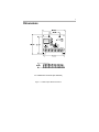
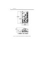
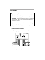
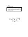
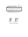
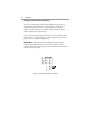
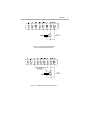
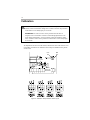
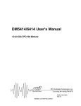
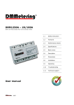
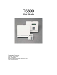
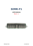
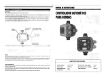
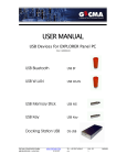
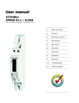
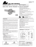
DC3R Isolation Option Board
User Guide
Instruction Manual D2-3454
The information in this manual is subject to change without notice.
Throughout this manual, the following notes are used to alert you to safety
considerations:
m
ATTENTION: Identifies information about practices or circumstances
that can lead to personal injury or death, property damage, or economic
loss.
IMPORTANT: Identifies information that is critical for successful application and
understanding of the product.
m
ATTENTION: Only qualified personnel familiar with the construction and
operation of this equipment and the hazards involved should install,
adjust, operate, and/or service this equipment. Read and understand
this instruction manual in its entirety before proceeding. Failure to
observe this precaution could result in severe bodily injury or loss of life.
ATTENTION: The user is responsible for conforming with all applicable
local and national codes. Failure to observe this precaution could result
in severe bodily injury or loss of life.
ATTENTION: The control circuit is at line potential when the drive is
energized. Use a non-metallic screwdriver when making adjustments to
the circuit board potentiometers. Exercise extreme caution as
hazardous voltage exists. Failure to observe these precautions could
result in severe bodily injury of loss of life.
ATTENTION: It is possible for a drive to run at full speed as a result of a
component failure. Please ensure that a master switch has been placed
in the AC line to stop the drive in an emergency.
ATTENTION: Reduce the chance of an electrical fire, shock, or
explosion by proper grounding, over-current protection, thermal
protection and enclosure. Follow sound maintenance procedures.
ATTENTION: This Drive contains ESD (Electric Static Discharge)
sensitive parts and assemblies, Static control precautions are required
when installing, testing, servicing, or repairing this assembly. Failure to
observe these precautions could result in damage to, or destruction of,
the equipment.
Corcom is a trademark of CII Technologies.
Reliance is a trademark of Rockwell International Corporation.
©1999 Rockwell International Corporation.
iii
m
ATTENTION: Starting and stopping with the inhibit terminal pins does
not disconnect AC power in the stop position. A hardwired AC power
disconnection switch must be mounted in close proximity to the
operator’s start/stop controls. This is required, as the DC3 drive does
not have an armature loop contactor. A single fault like a power device
short may cause motor rotation when in the stop mode. The user is
responsible for assuring safe conditions for operating personnel by
providing suitable guards, audio or visual alarms, or other devices.
Failure to observe these precautions could result in bodily injury.
iv
Contents
Introduction
1
Specifications
2
Dimensions
3
Connections . . . . . . . . . . . . . . . . . . . . . . . . . . . . . . . . . . . . . . . . . . . . . .5
Isolation option board connections . . . . . . . . . . . . . . . . . . . . . . . . . . . .5
Installation
5
Input voltage select switch . . . . . . . . . . . . . . . . . . . . . . . . . . . . . . . . . . .6
Speed adjust potentiometer connections . . . . . . . . . . . . . . . . . . . . . . . .7
Polarity reversal switch connections . . . . . . . . . . . . . . . . . . . . . . . . . . .8
Calibration
10
Voltage input signal calibration . . . . . . . . . . . . . . . . . . . . . . . . . . . . . . . .11
Calibration procedure . . . . . . . . . . . . . . . . . . . . . . . . . . . . . . . . . . . . .11
Current input signal calibration . . . . . . . . . . . . . . . . . . . . . . . . . . . . . . . .13
Calibration procedure: . . . . . . . . . . . . . . . . . . . . . . . . . . . . . . . . . . . . .13
Troubleshooting
Before troubleshooting
15
. . . . . . . . . . . . . . . . . . . . . . . . . . . . . . . . . . . .15
v
Illustrations
Figure 1. Isolation Option Board Dimensions . . . . . . . . . . . . . . . . . . . . . . . .3
Figure 2. Isolation Option Board Mounted on a Regenerative Drive . . . . . . .4
Figure 3. Isolation Option Board Connections . . . . . . . . . . . . . . . . . . . . . . . .5
Figure 4. Input Voltage Select Switch . . . . . . . . . . . . . . . . . . . . . . . . . . . . . .6
Figure 5. Speed Adjust Potentiometer Connections . . . . . . . . . . . . . . . . . . .7
Figure 6. Polarity Reversal Switch Connection . . . . . . . . . . . . . . . . . . . . . . .8
Figure 7. Open Collector PNP Transistor
. . . . . . . . . . . . . . . . . . . . . . . . . .9
Figure 8. Polarity Reversal Using NPN Transistor
Used as a Polarity Reversal Switch . . . . . . . . . . . . . . . . . .9
Figure 9. Calibration Trimpot and DIP Switch Layout . . . . . . . . . . . . . . . . .10
vi
1
Introduction
The isolation option board allows regenerative drives to accept a
grounded or floating DC voltage or current signal.
This manual contains specifications, installation procedures, connections,
and calibration procedures for the isolation option board. Refer to your
regenerative drive user’s manual for additional installation, operation,
and troubleshooting procedures.
2
Specifications
Power Requirements
Line input
Input Signal Ranges
Voltage signal, narrow range
Voltage signal, wide range
Current signal
Input Impedance
Voltage signal
Current signal, 1–5 mADC
Current signal, 4–20 mADC
Current signal, 10–50 mADC
Output
Voltage range, max
Linearity
Safety Certification
115VAC/230 VAC, 50/60 Hz, single phase
–25 to +25 VDC
–250 to +250 VDC
1–5 mADC, 4–20 mADC, 10–50 mADC
>25K ohms
1K ohms
235 ohms
100 ohms
–10 to +10 VDC
0.01%
UL Listed Component
cUL Listed Component
CE Approved Component
3
Dimensions
ALL DIMENSIONS IN INCHES [MILLIMETERS]
Figure 1. Isolation Option Board Dimensions
4
Dimensions
Figure 2. Isolation Option Board Mounted on a Regenerative Drive
5
Installation
m
ATTENTION: Only qualified personnel familiar with the constuction and
operation of this equipment and the hazards involved should install, adjust,
operate, and/or service this equipment. Read and understand this instruction
manual in its entirety before proceeding. Failure to observe this precaution
could result in severe bodily injury and loss of life.
ATTENTION: The user is responsible for conforming with all applicable local
and national codes. Failure to observe this precaution could result in severe
bodily injury or loss of life.
ATTENTION: This Drive contains ESD (Electric Static Discharge) sensitive
parts and assemblies, Static control precautions are required when installing,
testing, servicing, or repairing this assembly. Failure to observe these
precautions could result in damage to, or destruction of, the equipment.
Connections
Isolation option board connections
See Figure 3 for isolation option board connections. Isolation option board
terminals 1 through 4 are prewired on DC3R drives.
Figure 3. Isolation Option Board Connections
6
Installation
Input voltage select switch
m
ATTENTION: Change slide switch settings only when the drive is
disconnected from the AC line voltage. Make sure line voltage is set to its
correct position. If the switch is improperly set to a lower voltage position, the
motor will not run at full voltage and may cause transformer damage. If the
switch is improperly set to a higher voltage position, the motor will overspeed,
which may cause motor damage.
Set the input voltage select switch to 115 or 230 to match the AC line voltage. See
Figure 4 for switch location.
INPUT
VOLTAGE
SELECT
SWITCH
Figure 4. Input Voltage Select Switch
Installation
Speed adjust potentiometer connections
m
ATTENTION: Because the reference potentiometer is connected through the
regulator to the armature power circuit, its terminals are at line potential. Use
a potentiometer that has a insulating shaft to insulate the operator knob from
this power circuit and that is capable of withstanding Hi-pot tests at 2000
Volts DC for one minute. Failure to observe this precaution could result in
severe bodily injury or loss of life.
The isolation option board can be hooked up to speed adjust potentiometer instead
of following an external current or voltage signal. To control a motor in one
direction, hook up the speed adjust potentiometer as shown in Figure 5(a); for
bidirectional control, use the connection in Figure 5(b).
(a)
(b)
Figure 5. Speed Adjust Potentiometer Connections for
(a) Unidirectional Control and (b) Bidirectional Control
7
8
Installation
Polarity reversal switch connections
To reverse the output voltage polarity without changing the input voltage (or
current) polarity, connect POL REV to COM (terminal 11 to terminal 12). A
single-pole, single-throw switch can be used as a polarity reversal switch
(Figure 6). Close the switch to reverse polarity. Open the switch to return the
output voltage back to its original polarity.
An open collector PNP transistor may also be used to reverse the output voltage
polarity (Figure 7). Another alternative is to use an NPN transistor as shown in
Figure 11 to reverse the output voltage polarity.
IMPORTANT: If using an NPN transistor, additional components must be
installed. Install a 39K ohm resistor in series between Terminal 11 and the
transistor collector, and a 10K ohm resistor between Terminal 6 and the transistor
collector as shown in Figure 8.
Figure 6. Polarity Reversal Switch Connection
Installation
PNP
TRANSISTOR
Figure 7. Open Collector PNP Transistor
Used as a Polarity Reversal Switch
ADD 39K AND 10K
OHM RESISTORS
AS SHOWN
10K
39K
C
NPN
TRANSISTOR
B
E
Figure 8. Polarity Reversal Using NPN Transistor
9
10
Calibration
m
ATTENTION: The following adjustments are made with power on. Exercise
extreme caution as hazardous voltage exists. Failure to observe this precaution
could result in severe bodily injury or loss of life.
ATTENTION: The control circuit is at line potential when the drive is
energized. Use a non-metallic screwdriver when making adjustments to the
circuit board potentiometers. Exercise extreme caution as hazardous voltage
exists. Failure to observe these precautions could result in severe bodily injury
or loss of life.
All adjustments increase with CW rotation, and decrease with CCW rotation. Use a
non-metallic screwdriver for calibration. Each trimpot is identified on the printed
circuit board.
MAX
OUT
MIN
OUT
SIGNAL
INPUT ADJ.
SIGNAL
INPUT DIP
SWITCHES
Figure 9. Calibration Trimpot and DIP Switch Layout
Calibration
11
Voltage input signal calibration
The following maximum and minimum voltages should be known:
Vimin – Minimum voltage input signal.
Vomin – Minimum voltage output signal.
Vimax – Maximum voltage input signal.
Vomax – Maximum voltage output signal.
Vimin and Vimax is the voltage applied across terminals
7 and 8 (COM and INPUT 1) if the voltage input signal range is
0 – ±25 VDC, or across terminals 7 and 9 (COM and INPUT 2)
if the voltage input signal range is 0 – ±250 VDC. Vomin and Vomax is the
voltage across terminals 1 and 2 (OUT1 AND OUT2).
Calibration procedure
m
ATTENTION: The control circuit is at line potential when the drive is
energized. Use a non-metallic screwdriver when making adjustments to the
circuit board potentiometers. Exercise extreme caution as hazardous voltage
exists. Failure to observe these precautions could result in severe bodily injury
of loss of life.
ATTENTION: The DC3 drive is intended to operate at a predetermined
minimum speed. If the application requires zero speed operation, the user is
responsible for assuring safe conditions for operating personnel by providing
suitable guards, audio or visual alarms, or other devices. Failure to observe
these precautions could result in bodily injury.
Use a voltmeter for voltage measurements.
1. Switch all three of the SW501 DIP switches OFF as shown in
Figure 9 (page 12).
2. Connect the signal input as follows:
a. Connect signal common (–) to COM (terminal 7).
b. For 0 ± 25 VDC input signal, connect the signal
positive (+) to INPUT 1 (terminal 8); for 0 ± 250 VDC input signal,
connect the signal positive to INPUT 2 (terminal 9).
3. Adjust the regenerative drive’s MIN SPD trimpot full CCW and the MAX SPD
trimpot full CW.
4. Apply AC line voltage and voltage input signal.
5. Set the voltage input signal to Vimin.
6. Adjust the MIN OUT trimmer potentiometer (P503) so that the output voltage is
Vomin.
12
Calibration
7. Set the voltage input signal to Vimax.
8. Calculate the test point voltage, Vtp:
(Vimax) (m)
Vtp =
2
where
Vomax – Vomin
m =
Vimax – Vimin
9. Adjust the SIGNAL INPUT ADJ trimmer potentiometer (P501) so that the
voltage from COM to TP (terminal 7 to 10) is Vtp.
10. Adjust the MAX OUT trimmer potentiometer (P502) so that the voltage output
signal is Vomax.
11. Repeat steps 4, 5, 6, 7, 9, and 10. Use the same voltage values that you
previously calculated.
Calibration
13
Current input signal calibration
The following minimum and maximum values should be known:
Vomax - Maximum voltage output signal
Vomin - Minimum voltage input signal
Iimax - Maximum current input signal
Iimin - Minimum current input signal
Iimin and Iimax is the current applied through terminals 8 and 9 (COM and INPUT
1). Vomin and Vomax is the voltage applied across terminals 1 and 2 (OUT1 and
OUT2).
Calibration procedure:
m
ATTENTION: The control circuit is at line potential when the drive is
energized. Use a non-metallic screwdriver when making adjustments to the
circuit board potentiometers. Exercise extreme caution as hazardous voltage
exists. Failure to observe these precautions could result in severe bodily injury
of loss of life.
ATTENTION: The DC3 drive is intended to operate at a predetermined
minimum speed. If the application requires zero speed operation, the user is
responsible for assuring safe conditions for operating personnel by providing
suitable guards, audio or visual alarms, or other devices. Failure to observe
these precautions could result in bodily injury.
Use a voltmeter and ammeter for voltage and current measurements, respectively.
1. Switch only one of the SW501 DIP switches to the ON position (Figure 9, pg
12):
DIP switch 1 ON for 1–5 mA,
DIP switch 2 ON for 4–20 mA, or
DIP switch 3 ON for 10–50 mA.
2. Connect (but do not power) the current input signal as follows:
a. Connect the signal negative (–) to COM (terminal 7).
b. Connect the signal positive (+) to INPUT 1 (terminal 8).
3. Adjust the regenerative drive’s MIN SPD trimpot full CCW and the MAX SPD
trimpot full CW.
4. Apply both the AC line voltage and the current input signal.
5. Set the current input signal to Iimin.
6. Adjust the MIN OUT trimmer potentiometer (P503) so that the output voltage is
Vomin.
7. Set the current input signal to Iimax.
8. Calculate the test point voltage, Vtp:
14
Calibration
(Iimax) (m)
Vtp =
2
where
Vomax - Vomin
m=
Iimax - Iimin
9. Adjust the SIGNAL INPUT ADJ trimmer potentiometer (P501) so that the
voltage from COM to TP (terminal 7 to terminal 10) is Vtp.
10. Adjust the MAX OUT trimmer potentiometer (P502) so that the output voltage
is Vomax.
11. Repeat steps 4, 5, 6, 7, 9, and 10. Use the same voltage and current values that
you previously calculated.
15
Troubleshooting
m
ATTENTION: Dangerous voltages exist on the isolation option board and
regenerative drive when it is powered. When possible, disconnect the AC line
voltage from the isolation option board and regenerative drive while
troubleshooting. Be alert. High voltages can cause serious or fatal injury.
Before troubleshooting
Perform the following steps before starting any procedure in this section:
• Disconnect AC line voltage from the isolation option board adder board and
regenerative drive.
• Check the isolation option board and drive closely for damaged components.
• Check that no conductive or other foreign material has become lodged on the
printed circuit board.
• Verify that every connection is correct and in good condition.
• Verify that there are no short circuits or grounded connections.
• Check that the input voltage select switch is set to either 115 or 230 to match the
AC line voltage.
• Check that the regenerative drive’s rated armature and field outputs are
consistent with the motor ratings.
16
Troubleshooting
If there is no output
1. Measure the voltage output signal across terminals 1 and 2 (OUT1 and OUT2).
If there is a DC voltage present and there is no DC motor output, then check the
connections to the regenerative drive that it is connected to.
2. Check the voltage at terminals 3 and 4 (L1 and L2). If there is no voltage then
check the connections to the regenerative drive that it is connected to.
3. Check that the isolation option board board is receiving a voltage (or current)
input signal.
4. Check to see that the signal input ADJ trimmer potentiometer (P501) is not set
to the full CCW position.
If the unit is running at full speed
1. Check that the voltage output signal across terminals 1 and 2 (OUT1 and OUT2)
changes when the voltage (or current) input signal changes.
2. Check the wiring to the isolation option board board to the regenerative drive.
If the unit runs too slow or too fast
1. Check SW501 positions.
2. Check MIN SPD and MAX SPD trimpot calibrations.
If unit does not reverse
Check POL REV and COM connections.
Publication D2-3454 - December 1999 ©1999 Rockwell International Corporation. All rights reserved. Printed in USA