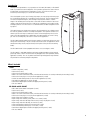
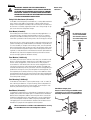
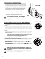
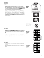
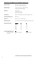
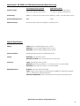
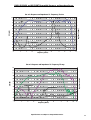
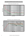
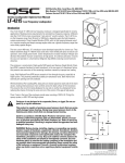
1
High-power Two-way Multi-Use Loudspeaker
• two 8-inch (203mm) neodymium magnet low-frequency drivers
• 1-inch throat compression high-frequency driver
• yoke mount
I-282H Speakon
®
input, pole cup, and floor-mount swivel feet. Bi-amp capable, 8 ohm
AD-S282H bi-amp capable, 8 ohm
AD-S282HT 70V/100V transformer equipped, bypassable to 8 ohm
*TD-000148-00*
TD-000148-00 rev.A
IMPORTANT SAFETY PRECAUTIONS
& EXPLANATION OF SYMBOLS
1- Read these instructions.
2- Keep these instructions.
3- Heed all warnings.
4- Follow all instructions.
5- Clean only with a dry cloth.
6- Install in accordance with QSC Audio Product’s instructions and a licensed, professional engineer.
7- Do not install near any heat sources such as radiators, heat registers, stoves, or other apparatus (including amplifiers) that produce heat.
8- Only use attachments/accessories from QSC Audio Products, Inc.
9- Use only with mounts or brackets specified by QSC Audio Products.
10- Refer all servicing to qualified personnel. Servicing is required when the apparatus has been damaged in any
way.
The exclamation point within an equilateral triangle is intended to alert the user to the presence of
important operating and maintenance (servicing) instructions in this manual.
WARNING! Before placing, installing, rigging, or suspending any speaker product, inspect all hardware,
suspension, cabinets, transducers, brackets and associated equipment for damage. Any missing, corroded, deformed or non-load rated component could significantly reduce the strength of the installation,
placement, or array. Any such condition severely reduces the safety of the installation and should be
immediately corrected. Use only hardware which is rated for the loading conditions of the installation
and any possible short-term unexpected overloading. Never exceed the rating of the hardware or equipment. Consult a licensed, professional engineer when any doubt or questions arise regarding a physical
equipment installation.
Warranty (USA only; other countries, see your dealer or distributor)
Disclaimer
QSC Audio Products, Inc. is not liable for any damage to amplifiers, or any other equipment that is caused by negligence or
improper installation and/or use of this loudspeaker product.
QSC Audio Products 3 Year Limited Warranty
QSC Audio Products, Inc. (“QSC”) guarantees its products to be free from defective material and / or workmanship for a period of
three (3) years from date of sale, and will replace defective parts and repair malfunctioning products under this warranty when the
defect occurs under normal installation and use - provided the unit is returned to our factory or one of our authorized service stations via pre-paid transportation with a copy of proof of purchase (i.e., sales receipt). This warranty provides that the examination
of the return product must indicate, in our judgment, a manufacturing defect. This warranty does not extend to any product which
has been subjected to misuse, neglect, accident, improper installation, or where the date code has been removed or defaced. QSC
shall not be liable for incidental and/or consequential damages. This warranty gives you specific legal rights. This limited warranty
is freely transferable during the term of the warranty period.
Customer may have additional rights, which vary from state to state.
In the event that this product was manufactured for export and sale outside of the United States or its territories, then this limited
warranty shall not apply. Removal of the serial number on this product, or purchase of this product from an unauthorized dealer,
will void this limited warranty.
Periodically, this warranty is updated. To obtain the most recent version of QSC’s warranty statement, please visit www.qscaudio.com.
Contact us at 800-854-4079 or visit our website at www.qscaudio.com.
© Copyright 2004, QSC Audio Products, Inc.
QSC® is a registered trademark of QSC Audio Products, Inc.
“QSC” and the QSC logo are registered with the U.S. Patent and Trademark Office
2
Speakon® is a registered trademark of Neutrik AG, OmniMount® is a registered trademark of OmniMount Systems, Phoenix, AZ, USA
Introduction
Thank you and congratulations on your purchase of the I-282H, AD-S282H, or AD-S282HT
multi-use, weather resistant loudspeakers. These products represent the state-of-the-art
in lightweight sound reinforcement loudspeaker systems. To get the most from your
investment, we encourage you to review this manual carefully.
These loudspeaker systems are full range, high output, two-way designs delivering superior sound quality and high SPL in a weather resistant enclosure. The low frequency drivers feature neodymium magnets, while the high frequency driver features a ferrite
magnet. The included yoke mount provides secure and versatile installation. These loudspeakers make an excellent choice for a wide variety of applications. All models include
an adapter plate for users who desire to use OmniMount®’s suitable loudspeaker mounting options.
The I-282H features two Speakon® connectors wired in parallel for fast, reliable connection and easy parallel connection of multiple loudspeakers. The Speakon connectors are
wired for passive or bi-amp use and have a selector switch for bypassing the crossover
when used in bi-amp applications. Additionally, the I-282H includes two swivel “outrigger” feet for converting the yoke mount to a floor monitor application.
The AD-S282H and AD-S282HT models feature weather resistant input wiring covers and
wiring strain relief bushings. They also include socket head screws for applications where
enhanced mounting security may be desired (used in place of the yoke mount retaining
knobs).
The AD-S282H model is bi-amp capable and features a crossover bypass switch.
The AD-S282HT is 70V/100V matching transformer equipped complete with an integral
power-tap selector switch. The transformer may be bypassed for low impedance (8 ohm)
application versatility. Two sets of parallel-connected input wiring barrier-strip terminals
are provided for connecting multiple loudspeakers.
What’s Included
I-282H
•I-282H loudspeaker (1 each)
•Yoke mount (1 each)
•Yoke mount retaining knobs (2 each)
•M10 x 1.0 x 23mm socket head screws, with flat and lock washers for security-enhanced yoke mounting (2 each)
•Yoke mount insert plugs for non-yoke mount applications (2 each)
•Swivel feet and retaining knobs for floor monitor applications (2 each)
•Self-adhesive rubber feet for swivels (4 each)
•Omni-Mount adapter plate and M4 self-tapping retaining screw (1 each)
•This User Manual
AD-S282H and AD-S282HT
•AD-S-282H or AD-S282HT loudspeaker (1 each)
•Yoke mount (1 each)
•Yoke mount retaining knobs (2 each)
•M10 x 1.0 x 23mm socket head screws, with flat and lock washers for security-enhanced yoke mounting (2 each)
•Yoke mount insert plugs for non-yoke mount applications (2 each)
•Input wiring cover and gasket (1 each)
•Input wiring cover retaining screws, M4 x 1.4 x 15 mm (2 each)
•Input wiring strain relief bushing with wire hole (2 each, may be part of cover)
•Input wiring strain relief bushing, no wire hole (1 each)
•Strain relief bushing retaining nut with wire hole (2 each)
•Strain relief bushing retaining nut, no wire hole (1 each)
•Omni-Mount adapter plate and M4 self-tapping retaining screw (1 each)
•This User Manual
3
Grill Removal
If it is necessary to remove the protective grill, do so with care as to avoid
bending or distorting the grill. The grill is held in place by two retaining
screws, one at the front edge of the top of the cabinet and one at the front
edge of the bottom.
Removing the Grill
1- Using a #2 Phillips-head screwdriver, remove the two grill retaining
screws.
2- Carefully pry the grill from its retaining groove using a plastic flat-blade
tool such as a plastic putty knife. Gently and evenly work the grill out of its
retaining groove to avoid bending the grill.
Coverage Angles
Before mounting the loudspeaker, determine the mounting orientation and desired coverage
angles. As supplied from the factory, the loudspeaker’s coverage angles are 90° (horizontal) x 60°
(vertical) with the cabinet oriented vertically. The waveguide can be rotated to interchange the
coverage angles.
Rotating the Waveguide to Alter HF Coverage Pattern
1- Remove the grill as outlined, above.
2- Remove the eight waveguide retaining screws. A #2-size Phillips screwdriver is recommended.
3- Reach into the waveguide’s port and pull gently to remove the waveguide. Be careful not to
damage the connections, wiring, or the gasket between the waveguide and the cabinet.
4- Rotate the horn 90° clockwise or counter clockwise and set it back in place. Make certain the
wiring is not stressed or pulled loose from its connections.
5- Before reinstalling the waveguide screws, lift the assembly a small distance and make sure
that the gasket is properly in place. Reposition it, if required. Set the waveguide in place and
reinstall the screws. Do not overtighten.
6- Replace the grill and install the upper and lower grill retaining screws.
4
Mounting
IMPORTANT! ENSURE THAT THE LOUDSPEAKER IS
MOUNTED PROPERLY AND A SAFETY CABLE IS INSTALLED
TO RETAIN THE LOUDSPEAKER IN THE EVENT OF A MOUNTING FAILURE. CONSULT A LICENSED, PROFESSIONAL ENGINEER WHEN ANY DOUBT OR QUESTIONS ARISE REGARDING
A PHYSICAL EQUIPMENT INSTALLATION.
Attach safety
cable here
Safety Cable Attachment (all models)
On the back of the loudspeaker, near the bottom, is a safety cable attachment
point. Install a safety cable strong enough to support several times the
weight of the loudspeaker assembly in the event it may fall. The cable must
be secured to a secondary support point which is also strong enough to support several times the loudspeaker’s weight.
Yoke Mount (all models)
The included yoke mount handles most surface mounting applications. It is
constructed of light, strong alloy and pre-drilled for ease of use. Integral
bushings at the cabinet contact points ensure ease of positioning. A large
center-hole is provided on the mounting surface side for wiring pass-through.
For enhanced security,
use the included M10
socket head screws to
secure the loudspeaker
to the yoke mount.
Mount the yoke to a surface strong enough to support the weight of the loudspeaker assembly using suitable hardware (not included). If any doubt exists
as to the suitability or strength of the mounting surface, consult a qualified
professional engineer. After securing the yoke to the mounting surface, have
an assistant hold the loudspeaker in place while installing either the retaining knobs or socket head screws with flat and lock washers (AD-S282H and
AD-S282HT only). Once the loudspeaker has been positioned for desired
acoustic coverage, tighten the hardware securely.
Floor Monitor (I-282H only)
The I-282H yoke mount comes with two swivel feet, four self-adhesive rubber feet, and retaining knobs. Attach the two of the rubber feet to each of
the two swivel outrigger bars, one at each end. Press firmly in place to
ensure adhesion. Then attach each of the two swivel outrigger bars to the
yoke mount using the two small retaining knobs included. The rubber feet
should be oriented away from the yoke mount. Swivel the outrigger bars perpendicular to the long axis of the yoke and tighten the retaining knobs. Set
the completed yoke assembly on the floor, resting on the rubber feet. Place
the loudspeaker into the yoke and secure using the two large retaining knobs
provided. Position the loudspeaker for desire acoustic coverage and tighten
the retaining knobs securely.
Pole Mounting (I-282H only)
On the bottom of the I-282H is a pole cup that accepts 1.375” or 1.500” (35
mm or 38 mm) pole diameters. For pole mounting, lift the loudspeaker into
position over the pole end and set it onto the pole. Ensure the pole is fully
and firmly seated into the pole cup of the loudspeaker.
OmniMount (all models)
For applications requiring the use of OmniMount’s Pro 60.0 mount, there is an
adapter plate included. The adapter plate is used between the OmniMount
bracket and the loudspeaker cabinet. Orient the plate with it’s curved side
toward the loudspeaker and its safety cable access cut-out toward the bottom of the loudspeaker. Attach to cabinet using the provided M4 x 18mm
self-tapping screw. Consult OmniMount’s literature and installation recommendations for proper and safe application of their product.
OmniMount adapter plateAttach to cabinet using provided M4 x 18mm
self tapping screw, then attach OmniMount
following manufacturer’s recommendations.
We recommend the use of M8 x 1.25 x 50mm bolts for securing
the OmniMount bracket to the loudspeaker cabinet.
5
Input Connection Cover (AD-S282H/HT models)
The loudspeaker includes a weather resistant cover for the input terminals. If
using the cover, be sure to pass the wiring through the bushing nut, bushing,
cover, and gasket before making connections.The input wiring cover is keyed
to fit one way only! Be sure the keyed end is oriented toward the bottom of the
loudspeaker cabinet. For proper sealing, we recommend #12 to #10 AWG (3.3
to 5.3mm2) stranded loudspeaker cable with a flat or twisted cross section. If
using smaller gauge wiring, it may be necessary to use additional weather
resistant compounds to achieve proper sealing of the wire entry points.
Input connection
cover assembly
•Pass the wires through the wire cover/gasket, bushing, and nut.
•Strip the wires and connect to barrier strip screw terminals.
•Slide the cover over the terminals and secure using the two machine
screws provided.
•Ensure gasket is seated properly; tighten compression nut.
To assure weather-tight connections, make sure the input
cover is installed with its keyed end toward the loudspeaker’s
bottom, fits flush against the loudspeaker cabinet, all gaskets
are properly placed, and has all hardware tightened sufficiently.
Bi-amp / Passive Mode Selector Switch (I-282H and AD-S282H models)
Mode selector switch
Before applying signal to the loudspeaker, ensure the BI-AMP / PASSIVE mode selector switch is set
to the appropriate position. Use a coin or flat-tipped screwdriver to change the switch position.
BI-AMP
Bi-amp mode requires pre-processing of the signal before the loudspeaker so that low-frequency
signal only is connected to the LF terminals, and high-frequency only signal is connected to the HF
terminals. The internal crossover network is bypassed completely when the switch is set to BI-AMP.
PASSIVE
Passive mode utilizes the loudspeaker’s internal crossover network and requires a full-range signal
be applied to the PASSIVE terminals. Do not use the terminals marker HF when using the loudspeaker in passive mode.
Set the mode selector switch to the appropriate position before applying signal to
the loudspeaker to avoid the possibility of damaging the drivers.
Transformer Tap Selector Switch (AD-S282HT
Set the transformer tap selector switch to the appropriate setting before applying audio. To select
the power level, align the tap selector switch slot with the desired power setting number. Use a coin
or flat tip screwdriver to operate the switch.
70V Distributed Systems: use the right side markings. Select from 25, 50, 100, or 200 watts.
100V Distributed Systems: use the left side markings. Select from 50, 100, or 200 watts. the X
position should not be used.
8 Ohm low impedance Systems: Set the tap selector switch to 8 ohms.
NOTE! 8 ohm setting should be used for 8 ohm audio systems only. Do not use 8
ohm setting when connecting the AD-S282T loudspeaker to 70V/100V distributed
audio systems.
Set the tap selector switch to the appropriate position before applying signal to
the loudspeaker to avoid the possibility of damage.
6
Transformer tap selector switch
Connection
I-282H
PASSIVE: Set the BI-AMP / PASSIVE selector switch to PASSIVE. Connect the full-range + input signal to Speakon pin 1+ and the full range input signal to Speakon pin 1-. The two Speakon connectors wired in parallel, allowing a second I-282H loudspeaker (also set for PASSIVE operation)
to be connected directly to the remaining Speakon connector.
I-282H
Speakon
pinout
ACTIVE: Set the BI-AMP / PASSIVE selector switch to BI-AMP. Connect the low frequency + signal to Speakon pin 1+ and the low frequency signal to Speakon pin 1-. Connect the high frequency + signal to Speakon
pin 2+ and the high frequency - signal to Speakon pin 2-. A second I-282H
loudspeaker (also set for BI-AMP operation) may be connected in parallel
by connecting it to the remaining Speakon connector using a four wire
Speakon connection.
Speakon plug
pinout as viewed
from wire-side
AD-S282H
PASSIVE: Set the BI-AMP / PASSIVE selector switch to PASSIVE.
Connect the input to the PASSIVE + and PASSIVE - terminals on the rear
of the loudspeaker. Do not use second set of terminals marked HF + and
HF -.
AD-S282H
terminal
pinout
BI-AMP: Set the BI-AMP / PASSIVE selector switch to BI-AMP. Connect the low frequency signal to the terminals marked LF + and LF -. Connect the high frequency signal to the terminals marked HF + and HF -.
AD-S282HT
Connect the input to one set of the + and - terminals on the rear of the
loudspeaker.
Additional loudspeakers may be connect to the second set of + and - terminals.
AD-S282HT
terminal
pinout
7
Specifications- AD-S282H (passive), AD-S282HT, I-282H (passive)
Frequency Range:
80- 27.7k Hz (-6 dB, free field response)
60- 29.5k Hz (-10 dB, free field response)
Maximum Output :
119dB SPL continuous rms output (calculated)
125dB SPL peak output (calculated)
Impedance:
8 ohms nominal
5.5 minimum at 17.6k Hz
64.2 maximum at 2.56k Hz
2
Power Rating :
400 watts rms (IEC 268-5, 8 hours, 50-20k Hz, 6dB crest factor)
Recommended Amp Power:
800 watts rms
Sensitivity:
93dB, 1 watt, 1 meter, free field (4 pi)
Nominal Coverage:
90° horizontal x 60° vertical with waveguide as installed at factory
Directivity Index and Q:
Frequency
500 Hz
1k Hz
2k Hz
4k Hz
8k Hz
16k Hz
Transformer (AD-S282HT only)
Taps (switch selectable)
8 ohm bypass
70V
25, 50, 100, and 200W
Yes
3
DI
6.2
9.5
11.0
9.5
8.5
8.0
Q
4.2
8.9
12.6
8.9
7.1
6.3
100V
50, 100, and 200W
Yes
Specifications are subject to change without notice.
8
Specifications- AD-S282H and I-282H with Recommended Signal Processing
Frequency Range:
Low Frequency Drivers (parallel)
70- 2.1k Hz (-6 dB, free field response)
60- 2.7k Hz (-10 dB, free field response)
High Frequency Driver
2.1k- 24.0k Hz (-6 dB, free field response)
1.9k- 24.0k Hz (-10 dB, free field response)
Power Rating:
400W (8 hrs., IEC268-5, 50- 2.0k Hz, 6dB crest factor) 50W (8 hrs., IEC268-5, 1.0k- 20.0k Hz, 6dB crest factor)
Recommended Amp Power:
800W
Nominal Coverage:
90° horizontal x 60° vertical with waveguide as installed at factory
100W
Physical Specifications
Weight:
I-282H: 28.5 lb. net, 36.8 lb. shipping (12.9 kg., 16.7 kg.)
AD-S282H: 27.7 lb. net, 35.6 lb. shipping (12.6 kg., 16.1 kg.)
AD-S282HT: 32.9 lb. net, 40.8 lb. shipping (14.9 kg., 18.5 kg.)
Enclosure and Grill:
painted high impact polystyrene, removable aluminum grill
Controls
AD-S282HT: rotary tap selector switch
AD-S282H and I-282H: Active / Passive mode selector rotary switch
Connectors:
I-282H- 2 NL4 Speakons wired in parallel
AD-S282H- barrier strip screw terminals, 1 set used for passive, 2 sets used for bi-amp
AD-S282HT- barrier strip screw terminals, 2 sets wired in parallel
Mounting Hardware:
All models- yoke mount with retaining knobs
I-282H- includes swivel outrigger feet, retaining knobs, and rubber feet, integral pole cup accepts
1.375” or 1.500” (35 mm or 38 mm) pole diameters
AD-S282H and AD-S282HT: includes socket head screws and washers for enhanced security
Specifications are subject to change without notice.
9
Dimensions
10
Specifications are subject to change without notice.
I-282H, AD-S282H, and AD-S282HT Beamwidth, Response, and Impedance Curves
On-axis Response and Impedance Vs. Frequency, Passive
SPL (dB)
Impedance (ohms)
SPL
Impedance
Frequency (Hertz)
On-axis Response and Impedance Vs. Frequency, Bi-amp
HF SPL
LF Impedance
HF Impedance
Impedance (ohms)
SPL (dB)
LF SPL
Frequency (Hertz)
Specifications are subject to change without notice.
11
I-282H, AD-S282H, and AD-S282HT Beamwidth and On/Off Axis Response Curves
Beamwidth (degrees)
Horizontal and Vertical Beamwidth Vs. Frequency
Horizontal
Vertical
Frequency (Hertz)
Response On-Axis, 15°, 30°,45°, and 60° Off-Axis Vs. Frequency
SPL (dB)
On Axis
15° Off Axis
30° Off Axis
45° Off Axis
60° Off Axis
Frequency (Hertz)
12
Specifications are subject to change without notice.
Painting the Loudspeaker
The loudspeaker enclosure, grill, and mount can be painted to match any decor, provided the following precautions are observed.
The cabinet is made of high impact polystyrene which requires controlled painting procedures in order to obtain good results. Use a
paint “system” designed for high impact polystyrene from any reputable paint supplier.
1- Remove the grill.
2- If painting mount and loudspeaker as a unit: Attach the ball mount or yoke mount.
3- Mask the loudspeaker’s input connector.
4- Mask the woofer, tweeter, and port being certain not to apply tape directly to the drivers. Alternatively, the inside of the grill can
be completely masked and set in place on the loudspeaker enclosure for painting.
5- Wash the components to be painted with a mild soap and hot water. Be careful not to get water on or into either of the drivers or
the input connections. Rinse with hot water. Allow to dry thoroughly.
6- Scuff-sand the components to be painted using red Scotchbrite® pad or 320 - 400 grit sandpaper.
7- Using compressed air, remove all dust from the components to be painted. Do not blow compressed air directly into either driver.
8- Clean the components to be painted.
9- Using a clean, lint-free, white cloth, wipe the components to be painted with suitable prep solution.
10- Apply adhesion promoter.
11- Apply primer topcoat.
12- Apply paint.
13- Allow to dry for at least 8 hours before handling.
13
Notes:
14
Notes:
15
How to Contact QSC Audio Products
Mailing address / Dirección postal / Adresse postale / 通信地址 :
QSC Audio Products, Inc.
1675 MacArthur Boulevard
Costa Mesa, CA 92626-1468 USA
Telephone Numbers / Números de teléfono / Téléphone / 电话 :
Main Number
USA (714) 754-6175
Sales & Marketing
USA (714) 957-7100 or toll free (USA only) (800) 854-4079
Customer Service
USA (714) 957-7150 or toll free (USA only) (800) 772-2834
Facsimile Numbers / Números de fax / Télécopieur / 传真 :
Sales & Marketing FAX
USA (714) 754-6174
Customer Service FAX
USA (714) 754-6173
World Wide Web / Site Web / 网址 :
www.qscaudio.com
E-mail / Dirección electrónica:
[email protected]
[email protected]
QSC Audio Products, Inc. 1675 MacArthur Boulevard Costa Mesa, California 92626 USA
©2004 “QSC” and the QSC logo are registered with the U.S. Patent and Trademark Office.