1
User Manual
Segway® Robotics Mobility Platform
440 SE
RMP 440 SE
Contents
Copyright, Disclaimer, Trademarks, Patent, and Contact Information..................................................................... 5
Introduction
Safety.......................................................................................................................................................................... 7
Abbreviations.............................................................................................................................................................. 9
RMP 440 SE
Included Components.............................................................................................................................................. 10
Capabilities................................................................................................................................................................. 11
Coordinate System....................................................................................................................................................12
Physical Characteristics............................................................................................................................................13
Mounting Locations...................................................................................................................................................14
User Interface Panel...................................................................................................................................................15
Powerbase Connections............................................................................................................................................16
Performance Specifications......................................................................................................................................17
Environmental Specifications...................................................................................................................................17
Endurance..................................................................................................................................................................18
Transportation and Shipping....................................................................................................................................20
Electrical Overview
System Architecture..................................................................................................................................................21
System Power.............................................................................................................................................................21
System Components................................................................................................................................................ 22
Operational Model
Operational States.................................................................................................................................................... 24
Faults......................................................................................................................................................................... 24
Initialization............................................................................................................................................................... 25
Diagnostic Mode....................................................................................................................................................... 26
Bootloader Mode...................................................................................................................................................... 26
Standby Mode........................................................................................................................................................... 26
Tractor Mode............................................................................................................................................................. 26
Disable Mode............................................................................................................................................................. 27
Copyright © 2013 Segway Inc. All rights reserved.
2
RMP 440 SE
Charging
Using the External Power Supply............................................................................................................................. 28
Charge Status LEDs.................................................................................................................................................. 28
Powering On/Off
Powering On.............................................................................................................................................................. 29
Powering Off.............................................................................................................................................................. 29
Connecting
Connector I................................................................................................................................................................30
Starter Breakout Harness..........................................................................................................................................31
Connector II............................................................................................................................................................... 32
Disable Button........................................................................................................................................................... 32
Additional Signals..................................................................................................................................................... 32
Connector IV............................................................................................................................................................. 33
Connecting To the RMP............................................................................................................................................. 34
Communication
General Command Structure................................................................................................................................... 37
Standard Motion Commands................................................................................................................................... 39
Omni Motion Commands..........................................................................................................................................40
Configuration Commands........................................................................................................................................ 42
Controller Input Mapping......................................................................................................................................... 53
RMP Response.......................................................................................................................................................... 56
IEEE754 32-bit Floating Point and Integer Representation..................................................................................... 67
Cyclic Redundancy Check (CRC)-16........................................................................................................................ 68
Fault Status Definitions............................................................................................................................................ 72
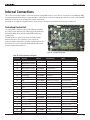
Internal Connections
Centralized Control Unit........................................................................................................................................... 78
Auxiliary Battery Board............................................................................................................................................. 79
Smart Charger Board................................................................................................................................................80
Communication.........................................................................................................................................................81
Hardware Controls.................................................................................................................................................... 87
Mode Selection......................................................................................................................................................... 88
Status Indicators....................................................................................................................................................... 88
CCU Input Power....................................................................................................................................................... 89
CCU Battery Supply.................................................................................................................................................. 89
Coin Cell Battery....................................................................................................................................................... 89
Copyright © 2013 Segway Inc. All rights reserved.
3
RMP 440 SE
Included Software
Installing the Software..............................................................................................................................................90
RMP CCU Bootloader Application.............................................................................................................................91
OCU Demo Application............................................................................................................................................. 92
Software License Agreement................................................................................................................................... 97
Maintenance
Fastener Torque......................................................................................................................................................... 98
Tire Pressure............................................................................................................................................................. 98
Parts List................................................................................................................................................................... 99
Removing Wheel Assemblies.................................................................................................................................. 100
Replacing Wheel Assemblies.................................................................................................................................. 100
Cleaning................................................................................................................................................................... 100
Software Updates.................................................................................................................................................... 100
Batteries
Replacing Batteries..................................................................................................................................................101
Installation and Removal Instructions................................................................................................................... 102
Transportation and Shipping.................................................................................................................................. 102
Proper Disposal....................................................................................................................................................... 102
Troubleshooting
Reporting Problems to Segway.............................................................................................................................. 103
Extracting the Faultlog............................................................................................................................................ 103
Reading the Faultlog............................................................................................................................................... 104
Faults....................................................................................................................................................................... 105
Charging Faults....................................................................................................................................................... 109
Other Issues............................................................................................................................................................ 109
Copyright © 2013 Segway Inc. All rights reserved.
4
RMP 440 SE
Copyright, Disclaimer, Trademarks, Patent, and Contact Information
Copyright © 2013 Segway Inc. All rights reserved.
Disclaimer
The Segway RMP is not a consumer product. Usage examples shown on rmp.segway.com have not necessarily been reviewed nor
approved by Segway Inc. ("Segway"). Segway is not responsible for end customer modifications or additions.
Trademarks
Segway owns a number of trademarks including, but not limited to, Segway and the Segway "flyguy" logo that have been registered
in the United States and in other countries. Those trademarks followed by ® are registered trademarks of Segway. All other marks are
trademarks or common law marks of Segway. Failure of a mark to appear in this guide does not mean that Segway. does not use the mark,
nor does it mean that the product is not actively marketed or is not significant within its relevant market. Segway reserves all rights in its
trademarks. All other trademarks are the property of their respective companies.
Xbox® is a registered trademark of Microsoft Corporation.
Logitech® is a registered trademark of Logitech International SA.
Segway Patent Information
The Segway RMP is covered by U.S. and foreign patents. For a patent listing, see http://rmp.segway.com/RMPPatents.pdf.
Contact Information
For support, please contact Segway Customer Care or use the RMP forum at http://rmp.segway.com/forum.
Segway Customer Care: 866-4SEGWAY (866-473-4929)
Fax: 603-222-6001
E-mail: [email protected]
Website: http://rmp.segway.com
Copyright © 2013 Segway Inc. All rights reserved.
5
RMP 440 SE
Introduction
The Segway Robotics Mobility Platform (RMP) is a robotic vehicle chassis and power-train designed to be integrated with additional
components to create robotic products. It is intended to be the mobility component for any number of robotic applications and as such
was designed with versatility, durability, and performance in mind.
Segway engineers have led the way with electric drive propulsion systems in the fields of battery management, advanced sensing, driveby-wire control, and dynamic stabilization. The RMP benefits from some of the same proprietary technology that has been deployed and
proven around the world as part of the Segway Personal Transporter (PT) line of products.
The RMP can handle high payloads, a variety of environmental conditions, and a wide range of operational scenarios. The chassis is
designed to handle a certain amount of abuse consistent with operation over rough terrain and in industrial environments. Control
parameters can be tweaked to make it easy to drive slowly around obstacles, at high speed in open spaces, or in any environment in
between.
Control of the RMP occurs via command and response messages sent over Ethernet, CAN, or USB interfaces. Commands are used to
control movement, set configuration parameters, and control response data. Response messages provide detailed information about
the current status of the RMP. Segway has chosen to allow users to control overall RMP movement, but not individual wheels/motors.
This frees users to treat the RMP as a single unit rather than a collection of components, and allows Segway to provide a more robust,
predicatable mobility platform.
To allow for the greatest possible control over the RMP's behavior, a variety of configuration parameters can be modified. However, it is
possible to set these parameters to unsafe values, so care must be taken when setting parameters to reduce the risk of damage or injury.
It is the user's responsibility to set configuration parameters to safe values. Be sure to follow all safety instructions in this document.
This manual describes the capabilities of the RMP and explains how to communicate with it. Integrators and engineers can use this
information to mount equipment on the RMP and write software for controlling the RMP.
Copyright © 2013 Segway Inc. All rights reserved.
6
RMP 440 SE
Safety
Improper use of the RMP can cause personal injury, death and/or property damage from loss of control, collision, and falls. To reduce risk
of injury, read and follow all instructions and warnings in this manual.
The following safety messaging conventions are used throughout this document:
WARNING!
Warns you about actions that could result in death or serious injury.
CAUTION!
Warns you about actions that could result in minor or moderate injury.
NOTICE
Indicates information considered important, but not related to personal injury. Examples include
messages regarding possible damage to the RMP or other property, or usage tips.
WARNING!
• Keep out of reach of children and pets. Unanticipated movement by the RMP could result in death or serious injury.
• Do not sit, stand, or ride on the RMP. Doing so could result in death or serious injury.
• Do not drive the RMP at people or animals. A collision could result in death or serious injury.
• Always alert people in the vicinity when an RMP is operating. An unexpected collision with the RMP could result in death or
serious injury.
• Avoid powering off on a slope. The RMP cannot hold its position when powered off and may roll downhill, causing serious
injury, death, or property damage.
• The RMP can accelerate rapidly. It is recommended that the RMP be securely raised so the wheels are off the ground (or
remove the wheels) until the user becomes familiar with the controls. Unanticipated movement by the RMP could result in
death or serious injury.
• Be careful when working with the DC power connections. You could shock yourself and/or damage the RMP.
• Remove batteries before working inside the RMP. You risk serious bodily injury from electric shock as well as damage to the
RMP.
• Do not submerge the RMP, batteries, or powerbases, in water. Do not use a power washer or high-pressure hose to clean
a RMP. Avoid getting water into any of the connectors. If you suspect the batteries or powerbase have been submerged or
experienced water intrusion, call Segway Technical Support immediately at 1-866-473-4929, prompt #2. Until you receive
further instructions, store the RMP upright, outdoors, and away from flammable objects. Failure to do so could expose you
to electric shock, injury, burns, or cause a fire.
• Unplug or disconnect the RMP from AC power before removing or installing batteries or performing any service. Never work
on any part of the RMP when it is plugged into AC power. You risk serious bodily injury from electric shock as well as damage
to the RMP.
• The cells within the batteries contain toxic substances. Do not attempt to open batteries. Do not insert any object into the
batteries or use any device to pry at the battery casing. If you insert an object into any of the battery's ports or openings
you could suffer electric shock, injury, burns, or cause a fire. Attempting to open the battery casing will damage the casing
and could release toxic and harmful substances, and will render the battery unusable.
• As with all rechargeable batteries, do not charge near flammable materials. When charging, the batteries heat up and could
ignite a fire.
• Do not use a battery if the battery casing is broken or if the battery emits an unusual odor, smoke, or excessive heat or leaks
any substance. Avoid contact with any substance seeping from the battery. Batteries contain toxic and corrosive matrials
that could cause serious injury.
• Observe and follow all safety information on the warning label found on the battery. Failure to do so could result in death,
serious injury, or property damage.
• Do not use cables that are frayed or damaged. You could shock yourself and/or damage the RMP.
• Use only Segway approved fasteners on the RMP. Other fasteners may not perform as expected and may come loose. Failure
to do so could expose you to risk of personal injury or property damage.
• Use assistance when moving or lifting the RMP. Single person lifting could result in serious injury.
Copyright © 2013 Segway Inc. All rights reserved.
7
RMP 440 SE
CAUTION!
• Be responsible about setting performance parameters. Read the relevant sections of this manual before changing any
performance parameters. The RMP follows commands issued to it, and it is the responsibility of the user to properly
safeguard their controls.
• Failure to charge the batteries could result in permanent damage to them. Left unplugged, the batteries could fully
discharge over time, causing permanent damage.
• Use only charging devices approved by Segway and never attempt to bypass or override their charging protection circuits.
• Always protect against electrostatic discharge (ESD) when working inside the RMP. The RMP could become damaged.
NOTICE
• This equipment has been tested and found to comply with the limits for a Class B digital device, pursuant to Part 15 of
the FCC Rules. These limits are designed to provide reasonable protection against harmful interference in a residential
installation. This equipment generates, uses and can radiate radio frequency energy and, if not installed and used in
accordance with the instructions, may cause harmful interference to radio communications. However, there is no guarantee
that interference will not occur in a particular installation. If this equipment does cause harmful interference to radio or
television reception, which can be determined by turning the equipment off and on, the user is encouraged to try to correct
the interference by one or more of the following measures:
•
Reorient or relocate the receiving antenna.
•
Increase the separation between the equipment and receiver.
•
Connect the equipment into an output on a circuit different from that to which the receiver is connected.
•
Consult the dealer or an experienced radio/TV technician for help.
• This Class B digital apparatus complies with Canadian ICES-003.
Cet appareil numérique de la classe b est conforme à la norme NMB-003 du Canada.
• Modifications not expressly approved by Segway may void the user's authority to operate this device under FCC regulations
and must not be made.
Copyright © 2013 Segway Inc. All rights reserved.
8
RMP 440 SE
Abbreviations
ABB
Auxiliary Battery Board — a PCB used to gather and report performance information from the auxiliary battery.
BCU
Battery Control Unit — a PCB inside the battery pack that manages the charge of the individual cells.
BSA
Balance Sensor Assembly — a group of PCBs used to obtain information about the vehicle's orientation.
CAN
Controller Area Network — a message-based protocol used for communication between microcontrollers.
CCU
Centralized Control Unit — a PCB that houses the SP, UIP, and NVM; it controls the RMP and handles communication.
CRC
Cyclic Redundancy Check — a type of error-detection used to verify the accuracy of transmitted data.
DLC
Data Length Code — a part of the CAN message header that specifies the size of the data packet being sent.
DTZ
Decelerate To Zero — an operational mode in which the RMP comes to a stop and powers down.
LE
Large Enclosure — a unified chassis/enclosure for 4-wheeled RMP models.
MCU
Motor Control Unit — a PCB that controls the electric motors that turn the wheels.
NVM
Non-Volatile Memory — a type of digital memory that can retain the stored information even when not powered.
OCU
Operator Control Unit — software and hardware that provide an interface between the user and the RMP.
PCB
Printed Circuit Board — a thin board with conductive pathways and electronic components mounted on it.
PSE
Pitch State Estimate — a 3-axis inertial estimate of the orientation of the RMP.
RMP
Robotics Mobility Platform — a propulsion system that can be used as a platform for making mobile robots.
SCB
Smart Charger Board — a PCB that controls battery charging functions.
SE
Small Enclosure — a box that contains all of the electrical components of the RMP.
SID
Standard ID — a CAN identifier that indicates the type of message being sent.
SOC
State Of Charge — a measurement of battery charge from 0% (empty) to 100% (full).
SP
Segway Processor — a microcontroller on the CCU that contains proprietary Segway code for controlling the RMP.
SPI
Serial Peripheral Interface — a synchronous serial data link standard that operates in full duplex mode.
UDP
User Datagram Protocol — a simple, transaction-oriented network protocol on top of TCP/IP.
UDFB
User Defined Feedback Bitmap — a stored value that indicates what feedback data should be sent to the user.
UI
User Interface — the means by which an operator interacts with a device.
UIP
User Interface Processor — a microcontroller on the CCU that communicates with the OCU.
USB
Universal Serial Bus — an industry-standard bus for communication and power supply between computers and peripherals.
VAB
Vicor Adapter Board — a PCB that interfaces with Vicor DC-DC converters.
Copyright © 2013 Segway Inc. All rights reserved.
9
RMP 440 SE
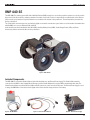
RMP 440 SE
The RMP 440 SE is a battery-powered Robotics Mobility Platform (RMP) meant to be used as the propulsion system for a robotic product.
It has four 21-inch all-terrain tires and two powerbases mounted on side rails. Electrical components are mounted inside a User Interface
(UI) box on the rear powerbase. Propulsion batteries are mounted to the bottom of the powerbases. The auxiliary battery is mounted to
the top of the UI box.
The on/off switch, external connectors, and indicator lights are mounted on an interface panel at the rear of the machine. Communication
with the RMP can occur over Ethernet, CAN, and USB.
Inside the UI box are the Centralized Control Unit (CCU), Auxiliary Battery Board (ABB), Smart Charger Board (SCB), and Power
Converter(s). Cables run from the UI box to the powerbases.
Figure 1: RMP 440 SE
Included Components
The RMP 440 SE comes with a Disable Button, Starter Breakout Harness, and External Power Supply. The Disable Button must be
connected for the RMP to enter Standby Mode. When pressed, the Disable Button will cause the RMP to immediately shut down. The
Starter Breakout Harness provides Ethernet, CAN, and USB connectors as well as leads for DC power. The External Power Supply is used
to charge the RMP. When connected, indicator lights on the UI box show the charge status of each battery.
Figure 2: Disable Button
Copyright © 2013 Segway Inc. All rights reserved.
Figure 3: Starter Breakout Harness
Figure 4: External Power Supply
10
RMP 440 SE
Capabilities
The RMP is meant to be used by integrators when creating mobile robotic products. As such, the RMP was designed with flexibility and
expandability in mind.
Driving
The RMP can drive forward, reverse, and can turn in place1. Turning is accomplished by skid steering — where the wheels actually skid
across the ground as the RMP turns. A variety of parameters can be adjusted for easier driving in different circumstances, making it
possible to have fine control at slow speeds and at high speeds. Adjustable parameters include maximum velocity, maximum acceleration,
maximum deceleration, maximum turn rate, and maximum turn acceleration.
Velocity control can either be velocity-based (m/s) or acceleration-based (m/s2). With velocity-based control the user continually
sends the desired velocity command (e.g. by holding a joystick steady to achieve a steady velocity). With acceleration-based control,
acceleration commands are sent until the RMP reaches the desired speed. Then an acceleration of zero is commanded in order to
maintain that speed. This is similar to using cruise control on the highway. See "Controller Input Mapping," p. 53, for more information
on the different types of control.
For safety, a disable button is provided with the RMP. When pressed, the disable button will cause the RMP to shut down. A Decel To Zero
(DTZ) command can also be sent, either by hardware button (not supplied) or by software command. This command causes the RMP to
decelerate and come to a stop before powering down.
Payload
Users can mount equipment to the rails along the sides of the RMP. Mounting holes are provided along the tops of the rails and on the
ends of the rails.
The maximum total payload is 180 kg (400 lbs), evenly distributed.
Communication
Communication with the RMP can occur over Ethernet, CAN, or USB. If using Ethernet the IP address, port number, subnet mask, and
gateway can all be configured. For both Ethernet and USB communications, a Cyclic Redundancy Check (CRC) is performed, which
verifies the accuracy of the transmitted data.
The RMP communicates via a polling method: the user sends a command and the RMP responds. Commands can be either motion
commands (that tell the RMP to move) or configuration commands (that set user-configurable parameters). Some of these parameters —
the User Defined Feedback Bitmaps — control what information is sent in the RMP response, allowing the user to receive only the relevant
data.
The RMP expects to receive commands within a frequency range (0.5 Hz - 100 Hz). If commands are issued too frequently the RMP will
ignore them. If commands are updated too slowly the RMP will slew the commands to zero.
Power
With an auxiliary battery, the RMP can provide power for additional equipment. The RMP 440 SE has space for two Power Converters. For
more information see "Power Converter," p. 23.
Control Interface
The user is responsible for creating an interface for communicating with and controlling the RMP. Details on how to communicate with
the RMP and interpret its responses are described later in this document (see "Communication," p. 36).
To make this process easier, Segway provides an OCU Demo Application and source code (see "OCU Demo Application," p. 92). This
application is fully functional, but is not intended to be an end solution. Instead it is meant to be used as a functional example of how to
interface with the RMP.
1
Turn radius is dependent upon the friction between the RMP tires and the ground. In some circumstances the RMP may not be able to turn in place.
Copyright © 2013 Segway Inc. All rights reserved.
11
RMP 440 SE
Coordinate System
The Balance Sensor Assembly (BSA) uses accelerometers and gyroscopes to determine the position and movement of the RMP, all of
which are used to create the Pitch State Estimate (PSE). This data is available to the user.
The RMP has a coordinate system relative to forward/reverse, pitch, roll, and yaw. This coordinate system is used when controlling the
RMP. The diagrams below show the RMP's axes and coordinate system.
Z
Ψ'
Φ'
Y
(Forward)
Θ'
X
Figure 5: RMP 440 SE Axes
Φ
Θ
Figure 6: RMP 440 SE Roll Axis
Figure 7: RMP 440 SE Pitch Axis
The variables listed below provide momentary information about the state of the RMP. For information on how to receive this data see
"User Defined Feedback Bitmaps," p. 56.
Table 1: BSA and PSE Variables
UDFB Variable
Symbol Measurement
Units
inertial_x_acc_g
X
Linear Acceleration
g
inertial_y_acc_g
Y
Linear Acceleration
g
inertial_x_rate_rps
X
Angular Velocity
rad/s
inertial_y_rate_rps
Y
Angular Velocity
rad/s
inertial_z_rate_rps
Angular Velocity
rad/s
pse_pitch_deg
Z
Θ
Angle (From Normal)
deg
pse_pitch_rate_dps
Θ'
Angular Velocity
deg/s
pse_roll_deg
Φ
Angle (From Normal)
deg
pse_roll_rate_dps
Φ'
Angular Velocity
deg/s
pse_yaw_rate_dps
Ψ'
Angular Velocity
deg/s
Copyright © 2013 Segway Inc. All rights reserved.
12
RMP 440 SE
Physical Characteristics
For product dimensions, please refer to the diagrams below. A summary of the major dimensions is provided in Table 2.
Note: product options may change the characteristics of the RMP.
Table 2: Physical Characteristics
Characteristic
Value
Overall
Length
1105 mm (43.5 in)
Width
842 mm (33.2 in)
Height
607 mm (23.9 in)
Chassis
177
6.97
990.60 1104.90
39.00
43.50
Length
991 mm (39.0 in)
Width
423 mm (16.6 in)
Height
322 mm (12.7 in)
Clearance
272 mm (10.7 in)
Tires
360
14.17
423.28
16.66
842.01
33.15
Figure 9: RMP 440 SE Back View
Copyright © 2013 Segway Inc. All rights reserved.
Wheel Base
572 mm (22.5 in)
Track Width
674 mm (26.5 in)
Recommended
Tire Pressure
6 psi
Weight
284.64
11.21
673.60
26.52
AT21x7-10
Other
Figure 8: RMP 440 SE Top View
505.18
19.89
Tire Size
406.70
16.01
524.18
20.64
106 kg (235 lbs)
607.13
23.90
305.10
12.01
533.40
21.00
571.50
22.50
Figure 10: RMP 440 SE Side View
13
RMP 440 SE
Mounting Locations
Equipment can be mounted to the RMP using the provided mounting locations. Tapped holes are located on the tops of the rails and on
the ends of the rails. Tapped holes are M8x12. Dimensions are mm [in].
M8 x 12 THREADS
876.30
34.50
774.70
30.50
673.10
26.50
571.50
22.50
488.95
19.25
387.35
15.25
304.80
12.00
203.20
8.00
98.14
3.86
50.80
2.00
330.50
13.01
Figure 12: RMP 440 SE End Mounting Holes
0
.00
391.64
15.42
0
.00
M8 x 12 THREADS
391.64
15.42
Figure 11: RMP 440 SE Top Mounting Holes
NOTICE
Only mount equipment via the provided mounting locations. Drilling holes in the enclosure or other modifications to the RMP may
adversely affect the FCC rating, IP rating, and/or structural integrity of the RMP.
Copyright © 2013 Segway Inc. All rights reserved.
14
RMP 440 SE
User Interface Panel
The power switch, LEDs, and external connectors for the RMP are all located on the User Interface Panel on the rear of the RMP. Users
should familiarize themselves with the various connectors and LEDs. For information on the connectors and what plugs into them see
"Connecting," p. 30.
Figure 13: Interface Panel
ON/OFF Switch
Use this switch to power on and off the RMP.
Power and Status LEDs
These two LEDs indicate what mode the RMP is in. They can be used to troubleshoot startup issues. See "Powering On/Off," p. 29, for a
list of what the LEDs indicate.
Connector I
This connector is used for communication and for auxiliary power. Communication available through this connector includes Ethernet,
USB, and CAN. Auxiliary power available depends on the Power Converters installed. Up to two different DC voltages can be made
available. The Starter Breakout Harness connects here.
Connector II
The Disable Button connects here. The Disable signal must be sent for normal operation. Other signals include: the Decel Request, used
to initiate a Decel to Zero (DTZ); the Boot1 signal, used to enter Diagnostic mode; and the Boot2 signal, used to enter Bootloader mode.
Connector IV
This connector is used in conjunction with the External Power Supply for charging the batteries of the RMP. For more information on
charging see "Charging," p. 28.
Charge Status LEDs
When charging the batteries, the Charge Status LEDs will light up, indicating the status of each of the batteries. Each LED corresponds to
a specific battery. For more information see "Charging," p. 28.
Auxiliary Battery
Battery 3
Battery 2
Battery 1
Battery 0
Figure 14: Battery Locations
Copyright © 2013 Segway Inc. All rights reserved.
15
RMP 440 SE
Powerbase Connections
On the side of the enclosure there are two powerbase connectors. The left-hand connector goes to the front powerbase; the right-hand
one goes to the rear powerbase. If there is only one powerbase, the left-hand connector is used. Powerbases must be plugged into the
proper connectors for the charge status LEDs to be correct.
Figure 15: Powerbase Connections
Connector V
Connect the primary (front) powerbase to this jack.
Connector VI
Connect the secondary (rear) powerbase to this jack.
Copyright © 2013 Segway Inc. All rights reserved.
16
RMP 440 SE
Performance Specifications
The RMP is driven by four independent and fully redundant brushless DC drive motors. It can operate both outdoors and indoors,
although the tires may damage carpet and scuff flooring. Traversable terrain includes asphalt, sand, grass, rocks, and snow.
All measurements are based on a standard RMP 440 SE with 21-inch wheels.
Table 3: Performance Specifications
Characteristic
Value
Mobility
Max. Speed
8.0 m/s (18 mph)
Turn Radius1
0 minimum
Turn Envelope1
1295.4 mm (51 in)
Max. Slope2
30°
Peak Torque
(Each Wheel)
100 N-m (74 lb-ft)
Wading Depth
(Standard Gearbox)
248 mm (9.7 in)
Wading Depth
(Inverted Gearbox)
406 mm (16.0 in)
Maximum Range3
50 km (30 mi)
Power
Run Time4
Up to 24 hours
Charge Time
2-3 hours
Battery Chemistry
LiFePO4
Propulsion Battery
Capacity
380 Wh each
Auxiliary Battery
Capacity
380 Wh
Payload
Max. Payload5
180 kg (400 lbs) centered
All-Terrain Payload
6
90 kg (200 lbs) centered
1
Turn-in-place capability and turning radius are dependent on the load conditions, operating surface type, tire friction, etc.
2
Based on an unloaded platform.
3
Based on an unloaded platform with 6 psi tires travelling in a straight line on level pavement. Actual performance may vary.
4
Run time based on internal battery power. Extended run time is possible with charger connected.
5
Turn-in-place and tight radius turns are not possible when operating on high traction surfaces with payloads at or near the maximum.
6
The maximum payload that will allow the RMP to turn in place even on high traction surfaces.
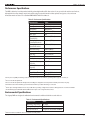
Environmental Specifications
The Segway RMP was designed to withstand environmental conditions both indoors and outdoors.
Table 4: Environmental Specifications
Characteristic
Value
Operating Temp. Range
0°–50° C
Storage Temp. Range
-20°–50° C
Ingress Protection
Designed to meet IP66 / NEMA 4
7
7
Batteries must be installed in order for enclosure to be fully sealed.
Copyright © 2013 Segway Inc. All rights reserved.
17
RMP 440 SE
Endurance
Platform endurance is determined by measuring battery draw while performing various maneuvers. The power used while performing
a maneuver describes the power used by a single battery. Because all four propulsion batteries are used evenly, the runtime of a single
battery can be used to approximate the runtime of the entire propulsion system.
In many cases the propulsion batteries will limit the runtime of the RMP. However, there are some scenarios in which the auxiliary battery
will be the limiting factor. Such cases include stationary operation and situations in which additional equipment is using the auxiliary
battery as a power source.
To calculate the energy used by a given maneuver, first determine the length of time the maneuver will be performed. Then multiply that
time (in hours) by the Watts used while performing the maneuver. This will give you the Watt-hours used. Subtract those Watt-hours from
the Watt-hours remaining in the battery. Maximum battery capacity is 380 Watt-hours.
Stationary Power Usage
When the RMP is maintaining a stationary position on level ground, the auxiliary battery is the limiting factor when calculating
runtime. The internal RMP components use approximately 16 Watts, allowing the auxiliary battery to last nearly 24 hours. In contrast,
the propulsion motors require only 7 Watts to maintain position on level ground, leaving 55% SOC left in the propulsion batteries
after 24 hours. During actual use, the power used by the propulsion batteries may be greater, especially if maintaining position on a
slope.
Straight Line Power Usage
The following empirical relationships can be used to provide a rough estimate of power usage when travelling in a straight line. These
relationships are based on tests performed on dry, level pavement and represent best-case scenarios. Actual performance may vary.
Power draw for an unloaded platform:
–0.16
W = 29.38 × p
1.137
×v
W = Power Draw (Watts)
p = Tire Pressure (psi)
v = Velocity (m/s)
Power draw for a platform with 400 lbs additional mass:
–0.5
W = 96 × p
1.1
×v
W = Power Draw (Watts)
p = Tire Pressure (psi)
v = Velocity (m/s)
Turn-in-Place Power Usage
Due to the nature of scrub steering, the RMP uses considerable power when turning in place. The information provided here is based
on tests performed on dry, level pavement with tire pressure at 6 psi and 12 psi. Tests were performed at 1 rad/s. Greater speeds
caused the RMP to become unstable and are not recommended. Actual performance may vary.
Above 400 Watts the RMP cannot turn continuously. This is represented by the grey area in the graph below.
Turn-in-place power usage at 1 rad/s can be approximated using the
following equation:
W = 2.24m + 181
W = Power Draw (Watts)
m = Additional Mass (lbs)
Figure 16: Turn-in-Place Power Usage
Copyright © 2013 Segway Inc. All rights reserved.
18
RMP 440 SE
Endurance (cont.)
Turning Power Usage
When driving in circles or turning, power usage is based on the turning radius and the speed. The information provided here is based
on tests performed on dry, level pavement with tire pressure at 6 psi and 12 psi. The smaller the radius, the more power is used.
Actual performance may vary.
Figure 17 shows the power usage for an RMP with no additional mass. As mass increases, power usage also increases. The equations
below can be used to estimate power usage for an unloaded platform and for a platform with 100 lbs additional mass.
Figure 17: Turning Power Usage, Unloaded
The following empirical relationships can be used to approximate power usage when driving in circles.
Power draw for an unloaded platform:
–0.96
W = (215v + 145)r
W = Power Draw (Watts)
v = Velocity (m/s)
r = Radius (m)
Power draw for a platform with 100 lbs additional mass:
–1.04
W = (410v + 364)r
W = Power Draw (Watts)
v = Velocity (m/s)
r = Radius (m)
Copyright © 2013 Segway Inc. All rights reserved.
19
RMP 440 SE
Transportation and Shipping
NOTICE
Lithium-ion batteries are regulated as "Hazardous Materials" by the U.S. Department of Transportation. For more information, contact the
U.S. Department of Transportation at http://www.phmsa.dot.gov/hazmat/regs or call 1-800-467-4922.
To prevent damage to your RMP, always ship it in the original crate it came in. The crate disassembles for storage. If you do not have the
original crate, contact Segway for a replacement (see "Contact Information," p. 5).
Copyright © 2013 Segway Inc. All rights reserved.
20
RMP 440 SE
Electrical Overview
This section describes the components of the RMP and shows how they interact.
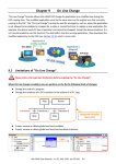
System Architecture
The RMP combines the robustness of the Segway powerbase with a versatile Centralized Control Unit (CCU). The powerbase is the
same proven technology used in the Segway Personal Transporter (Segway PT). It controls the wheels, senses the RMP's orientation,
and provides a mounting location for the batteries. The Centralized Control Unit coordinates the RMP's movement and controls
communication among all the components. It acts as the interface between the RMP and the outside world. The diagram below shows
how these components communicate with each other.
Figure 18: System Architecture Diagram
System Power
The RMP runs on rechargeable batteries. Power is routed from the batteries to the various components of the system. DC power is
available for customer use.
Figure 19: System Power Diagram
Copyright © 2013 Segway Inc. All rights reserved.
21
RMP 440 SE
System Components
A brief overview of each component is provided to help you become familiar with these components and their functions.
Centralized Control Unit
The Centralized Control Unit (CCU) contains the Segway Processor (SP)
and the User Interface Processor (UIP). These processors use synchronized
timing to control the RMP in real time. They communicate via a Serial
Peripheral Interface (SPI) link.
Segway Processor
The SP controls essential system functions including timing
management, control algorithms, safety kernel functions, redundancy
management, estimation algorithms, and Segway hardware interfaces.
In addition, a real time clock and Non-Volatile Memory (NVM) allow for
diagnostic fault logging.
User Interface Processor
Figure 20: Centralized Control Unit
The UIP controls the interaction between the user and the RMP. It allows the user to command RMP motion, configure machine
parameters, and access faultlog information.
The UIP consists of four layers: System layer, I/O layer, Toolkit layer, and Application layer.
1. The System layer manages hardware-specific functionality like interrupts and timing.
2. The I/O layer manages all processor I/O including GPIO, ADC, DAC, CCP, USB, UDP, CAN, RS232, TTL Serial, and the SPI link.
The I/O layer is responsible for gathering all raw UIP data and presenting it to the Toolkit layer.
3. The Toolkit layer abstracts the information gathered by the I/O layer and interprets it into meaningful system level data. The
Toolkit layer then relays that information to various interfaces for consumption by the user.
4. The Application layer consists of an application stump for future expansion and development of the system.
Powerbase
The powerbase is one of the main components of the Segway PT and has been leveraged for use as the propulsion unit of the RMP. Each
RMP 440 SE has two powerbases, one for the front wheels and one for the rear wheels. Inside each powerbase are two Motor Control
Units (MCUs). Only the front powerbase contains a BSA. The powerbase is not serviceable by the user; this information is provided for
completeness only.
Motor Control Unit
The MCU is a Segway motor drive. It utilizes the robustness of the
Segway PT propulsion system as a motor drive. Each MCU has two motor
drives that drive half of a dual hemisphere Segway motor. Each MCU
performs its own internal fault detection and communicates with the SP
via CAN interface. The user does not have access to the MCU interface.
Front
MCU 0
BSA
MCU 1
Balance Sensor Assembly
The BSA provides redundant raw three-axis inertial data to the SP. The
SP uses this information to compute the Pitch State Estimate (PSE). The
PSE algorithm estimates the machine orientation and movement based
on the combined raw inertial information and wheel odometry.
MCU 2
MCU 3
Rear
Figure 21: Segway Powerbases
Copyright © 2013 Segway Inc. All rights reserved.
22
RMP 440 SE
Smart Charger Board
The Smart Charger Board (SCB) distributes charging current from the
External Power Supply to the ABB and both powerbases. It controls multiple
high current smart chargers and manages charging. It has 5 monitored
channels at 100 VDC each and can perform fault detection down to the level
of the power supply, board, and battery.
Figure 22: Smart Charger Board
Auxiliary Battery Board
The Auxiliary Battery Board (ABB) monitors voltage, current, state of charge,
and battery flags of the auxiliary battery pack. It has software protected
outputs to prevent over-discharge of the battery. The board can act as a
standalone unit or can connect to the CCU. It interfaces with the UIP via CAN
and provides real-time battery data and status information for the auxiliary
battery pack. The ABB can communicate via CAN, USB, and RS232.
If the fuse blows, the entire board must be replaced.
Figure 23: Auxiliary Battery Board
Power Converter
The RMP 440 SE accommodates up to two Power Converters. Each Power
Converter accepts 72 VDC input power and provides DC output power at a
different voltage. One Power Converter provides 12 VDC power for internal
use and customer use. The other Power Converter is selectable at time of
purchase. Output voltage options include 5 VDC, 12 VDC, 24 VDC, 36 VDC,
and 48 VDC.
Figure 24: Power Converter
Copyright © 2013 Segway Inc. All rights reserved.
23
RMP 440 SE
Operational Model
This chapter describes powering on, powering off, and the various modes of operation.
Operational States
At any given time, the RMP will be in one of the following operational states:
•
Initialization
•
Diagnostic Mode
•
Bootloader Mode
•
Standby Mode
•
Tractor Mode
•
Disable Mode
•
Off
Figure 25 shows how these states interact. Each of these states is discussed in more depth on the following pages.
Figure 25: System State Diagram
Faults
Faults occur in response to events that impact the RMP. This could include anything from receiving a user-commanded DTZ signal
to detecting a failed battery. Sometimes faults are the result of a problem that needs to be resolved. Other times they are merely
informative.
In response to a fault the RMP may simply log the fault or it may take an action. There are four types of fault responses:
•
No fault response — fault is logged. No change in RMP behavior.
•
DTZ response — fault initiates a Decel To Zero. RMP comes to a stop, logs the fault, and powers off.
•
Disable response — fault causes RMP to power off. RMP logs the fault and powers off immediately.
•
Disable MCU response — fault causes a single MCU to go down. RMP will continue to operate unless the other MCU in the
powerbase goes down as well.
Copyright © 2013 Segway Inc. All rights reserved.
24
RMP 440 SE
Initialization
Initialization is composed of three sub-states: Init Hardware, Init Propulsion, and Check Startup Issues. First, the hardware is initialized;
this includes the CCU and ABB. Then, propulsion is initialized (the MCUs and BSA). If there are no issues with the system, the RMP
transitions to Standby Mode. Otherwise it shuts down.
If the BOOT1 or BOOT2 signal is pulled low the RMP will enter Diagnostic Mode or Bootloader Mode, respectively.
Init Hardware
During Init Hardware, the following steps are performed:
1. UIP and SP initialize hardware, interrupts, and software.
2. UIP and SP synchronize their timing.
3. UIP-SP communication is established.
4. SP reads configuration parameters from NVM, initializes dependent data, and passes the parameters to the UIP for UIP
dependent data initialization.
5. UIP and SP verify configuration validity.
6. SP extracts the faultlog from NVM and relays the faultlog array to the UIP for user access.
Init Propulsion
During Init Propulsion the SP initializes each MCU using a state machine. Each state verifies a certain MCU operational status. If any MCU
is not operating as expected, the RMP will transition to Disable Mode and power off. Information regarding the failure is stored in the
faultlog
Check Startup Issues
In this sub-state the SP checks for various parameters that will gate entry to Standby Mode. When the RMP detects an issue, Standby
Mode entry is gated and the RMP will emit a tone and blink the LEDs for five seconds before failing initialization. If the issue is corrected in
this time, the transition to Standby Mode will be allowed.
The following issues will gate transition to Standby Mode:
•
An MCU declares a fault.
•
The RMP is charging (this can be overridden: see "RMP_CMD_SET_INPUT_CONFIG_BITMAP," p. 46).
•
An MCU battery open circuit voltage is below the operational threshold.
•
An MCU battery state of charge is below the operational threshold.
•
7.2 VDC battery (if present) has low or high voltage.
•
Any detected machine motion (RMP moving un-commanded).
•
Tractor mode request is present from the user.
•
BSA communication has not been established.
Copyright © 2013 Segway Inc. All rights reserved.
25
RMP 440 SE
Diagnostic Mode
In Diagnostic Mode the RMP stays in the Init System state without transitioning to Standby Mode. In this mode the RMP has initialized
the CCU and ABB, but has not initialized propulsion. The user can communicate with the RMP but cannot command it to move. This mode
allows the user to update configuration parameters and extract the faultlog without fully initializing the RMP; this is useful when a fault
causes the RMP to shutdown before entering Standby Mode.
In this state the RMP will remain on as long as power is available.
To enter Diagnostic Mode:
1. Turn the RMP off.
2. Connect pins D and E on the 6-pin connector (for the full pinout, see "Connector II," p. 32).
3. Use the USB cable to connect the RMP to the computer. The RMP will power on.
This will pull the BOOT1 signal low. The RMP will begin initialization but will stop at Init System and remain there.
Bootloader Mode
In Bootloader Mode, the RMP remains in the bootloader stage without continuing on to the RMP applications. The user can then load new
applications into either of the processors using the Bootloader Application (see "RMP CCU Bootloader Application," p. 91).
In this state the RMP will stay powered as long as USB power is available.
To enter Bootloader Mode:
1. Turn the RMP off.
2. Connect pins D and F on the 6-pin connector (for the full pinout, see "Connector II," p. 32).
3. Use the USB cable to connect the RMP to the computer. The RMP will power on.
This will pull the BOOT2 signal low. The RMP will stop at the bootloader stage without loading any applications or beginning initialization.
Standby Mode
In Standby Mode the RMP is fully functional with the exception that motion commands are not executed. The MCUs are enabled, the
controllers are initialized, and the RMP is holding its position. Any motion commands issued will not be executed by the platform.
Standby mode is entered automatically after successful initialization. From here the user can initiate a transition to tractor mode or
disable the RMP.
Tractor Mode
In Tractor Mode the RMP will accept motion commands from the user. This is the only mode in which the RMP can be commanded to
move. In this state the MCUs are enabled and the controllers are running. Motion commands issued by the user will be accepted.
Tractor Mode can only be entered from Standby Mode as the result of a user mode request (see "RMP_CMD_SET_OPERATIONAL_MODE,"
p. 50). From here the user can initiate a transition back to Standby Mode or can disable the RMP.
Copyright © 2013 Segway Inc. All rights reserved.
26
RMP 440 SE
Disable Mode
WARNING!
When the RMP powers off it may continue to move (for example, it could roll downhill). This could cause personal injury and property
damage.
In Disable Mode the RMP performs housekeeping functions and then powers off. In this mode the propulsion drives are disabled and all
user commands are ignored.
In this mode the following actions are performed:
1. Drives are disabled via software and hardware.
2. The ABB shuts down the protected +72 V output.
3. The processors go into reset.
4. The RMP powers off.
If the RMP is powered off via the on/off switch, none of the above housekeeping functions are performed. The recommended way to
power off the RMP is to send a powerdown request (see "RMP_CMD_SET_OPERATIONAL_MODE," p. 50, and "Powering Off," p. 29).
Disable Mode can be entered at any time via user command (see "General Command Structure," p. 37). Some faults will also cause a
transition to Disable Mode.
Copyright © 2013 Segway Inc. All rights reserved.
27
RMP 440 SE
Charging
WARNING!
Do not plug in the charger if the charge port, power cord, or AC power outlet
is wet. You risk serious bodily injury or death from electric shock as well as
damage to the RMP.
CAUTION!
Failure to charge the batteries could result in damage to the batteries. Left
unplugged, the batteries could fully discharge over time, causing permanent
damage. Use only charging devices approved by Segway.
Table 5: External Power Supply Input/Output
Characteristic
Value
Input Voltage
100-250 VAC 50/60 Hz
Max. Input Current
2.4 A @ 100 VAC per channel
Output Voltage
57-95 VDC
Output Current
2.1 A per channel
The RMP 440 SE requires the External Power Supply to charge the batteries.
This power supply converts AC power to DC power for use by the RMP. The
Smart Charger Board inside the RMP distributes this power as needed to the
batteries for charging.
Charging requires that the temperature be within 0° C – 50° C and the
humidity be <90%, non-condensing.
Using the External Power Supply
Figure 26: RMP 440 SE Interface Panel
An External Power Supply is supplied with the RMP 440 SE.
The charge port (Connector IV) is located on the interface panel next to the
Charger Status LEDs.
1. Connect the External Power Supply to the charge port on the RMP
(Connector IV).
2. Plug the External Power Supply into a standard AC wall outlet.
3. Turn on the External Power Supply by toggling the switch.
Charge Status LEDs
There is one LED for each 72 V Segway battery attached to the RMP. When
charging, the LEDs turn green. If a battery is at maximum charge, its LED
blinks. See Table 6 for a complete list of what the LEDs indicate.
NOTICE
If the RMP is already charging and the RMP is powered on, the RMP will error
and turn itself off. This is to prevent users from turning on the RMP and
driving it away while it is still plugged in. This functionality can be changed
by disabling the AC Present CSI in the Input Config Bitmap (see "RMP_CMD_
SET_INPUT_CONFIG_BITMAP," p. 46).
Figure 27: External Power Supply, Front
Table 6: Battery LEDs
LED Status
Meaning
Off
Battery is not charging.
Green
Battery is charging.
Green Blinking
Battery in balance mode. The time
between blinks gets longer as the
cells come into balance.
Red
Fault or battery not present.
Red Blinking
Charging fault. See "Charging
Faults," p. 109.
Copyright © 2013 Segway Inc. All rights reserved.
Figure 28: External Power Supply, Back
28
RMP 440 SE
Powering On/Off
This section describes how to turn the RMP on and off.
Powering On
The RMP can be turned on and off using the toggle switch mounted on the interface panel. Plugging in the USB connector will also power
on the RMP.
When successfully powered on, the RMP enters Standby mode, which is indicated by a blinking yellow LED and a solid green LED.
1. Make sure the disable button is connected and has not been pressed.
2. Flip the toggle switch to ON or connect via USB.
3. Wait for the RMP to enter Standby mode.
NOTICE
• Auxiliary power will not be available unless the toggle switch is ON.
• If the red LED blinks rapidly and then turns off, double-check the disable button (see "Troubleshooting," p. 103). If powered from
USB, try disconnecting USB cable and toggling on/off switch ON.
Table 7 shows the various operational modes and LED indicator patterns.
Table 7: Indicator LEDs
Mode
Power LED
Status LED
System Initialization
Yellow Blinking
Off
Standby Mode
Yellow Blinking
Green Solid
Tractor Mode
Yellow Blinking
Green Blinking
Bootloader Mode
Yellow/Red Toggling
Off
Diagnostic Mode
Red Blinking, Sync'd
Green Blinking, Sync'd
Reset Processors
Red Blinking Rapid
Off
Disable Power
Red Solid
Off
Powering Off
There are a few ways that the RMP can be powered off. Each is described in Table 8 below.
WARNING!
When the RMP powers off it may continue to move (for example, it could roll downhill). This could cause personal injury and/or property
damage.
Table 8: Power Down Methods
Method
Resulting Behavior
User commanded Power Down
The RMP powers down normally, performing housekeeping tasks. No fault is logged.
User commanded Disable
The RMP logs the disable request as a fault and powers down.
User commanded Decel To Zero (DTZ)
The RMP comes to a stop, logs the DTZ request as a fault, and powers down.
On/Off switch is set to off
Power is immediately removed from the system. No housekeeping tasks are performed.
The RMP immediately shuts down.
Disable button is pressed
The RMP logs the disable button press as a fault and powers down.
Hardware DTZ input
The RMP comes to a stop, logs the DTZ Input as a fault, and powers down.
NOTICE
A fault response may also result in the machine powering off.
Copyright © 2013 Segway Inc. All rights reserved.
29
RMP 440 SE
Connecting
This chapter describes how to connect to the RMP. Included are the pinouts for all the panel connectors as well as detailed descriptions of
the Starter Breakout Harness and the Disable Button.
Connector I
Connector I is the largest external connector on the RMP. This approximately
2-inch diameter connector is a MIL-DTL-38999/24FJ4SN connector with 56
pins. It houses all the communication interfaces to the platform and provides
power available for customer loads.
Communication interfaces passing through this connector are Ethernet, USB,
and CAN. Power available is dependent upon which Power Converters have
been selected. Power is only available when the auxiliary battery option is
included.
This is a MIL-DTL-38999/24FJ4SN socket. Mating connector is a
MIL-DTL-38999/26FJ4PN plug.
Figure 29: 56-Pin Connector
Table 9: Connector I Pinout
Pin
Signal
Pin
Signal
A
ETHERNET TX+
m
RADIO3
b
ETHERNET TX–
M
RADIO4
B
ETHERNET RX+
N
RADIO5
c
ETHERNET RX–
n
RADIO6
C
USB_VBUS
P
RADIO_GND
D
USB_D+
K
RADIO+5V
d
USB_D–
J
LCD_POWER+5V
E
USB_ID
h
SERIAL_GND
e
USB_GND
y
POWER_1+
F
SERIAL_TX
z
POWER_1–
f
SERIAL_RX
AA
POWER_2+
G
CAN1H
JJ
POWER_2+
g
CAN1L
DD
POWER_2–
H
CAN1_GND
LL
POWER_2–
k
RADIO1
FF
POWER_3+
L
RADIO2
EE
POWER_3–
1
1
Not fully supported at time of printing.
1
Copyright © 2013 Segway Inc. All rights reserved.
30
RMP 440 SE
Starter Breakout Harness
The RMP is supplied with a breakout harness that connects to the 56-pin connector. This harness screws onto Connector I and
provides all the connections necessary to communicate with the RMP. It provides Ethernet, USB Type A, and CAN plugs as well as
leads for power. The connector is fully mated when the red stripe on Connector I is no longer visible.
Figure 30: Starter Breakout Harness
Figure 31: Starter Breakout Harness Pins
Ethernet
10 Mbps Ethernet is available on the 56-pin connector (see pinout, Table 10). The starter breakout harness includes a male RJ45
Ethernet plug.
Table 10: Ethernet Pinout
RJ45 Pin
Signal
Connector I Pin
1
Ethernet TX+
A
2
Ethernet TX–
b
3
Ethernet RX+
B
6
Ethernet RX–
c
Figure 32: RJ45 Plug
USB
USB 2.0 compliant interface is available on the 56-pin connector (see pinout, Table 11). The starter breakout harness includes a male
USB Type A plug.
Table 11: USB Pinout
Figure 33: USB Plug
USB Pin
Signal
Connector I Pin
1
USB_VBUS
C
3
USB_D+
D
2
USB_D–
d
4
USB_GND
e
Housing
Chassis Ground Housing
CAN
Controller Area Network connection is available on the 56-pin connector (see pinout, Table 12). The starter breakout harness includes
a male DB9 connector for CAN communication.
Table 12: CAN Pinout
DB9 Pin
Signal
Connector I Pin
7
CAN1H
G
2
CAN1L
g
3
CAN1_GND
H
Figure 34: Male DB9 Connector
Copyright © 2013 Segway Inc. All rights reserved.
31
RMP 440 SE
Power
The auxiliary battery feeds Power Converters (number of converters varies from depending on RMP model). At time of purchase, the
customer has the option to select the output voltage of the Power Converters. Possible options are: 5 VDC, 12 VDC, 24 VDC, 36 VDC,
and 48 VDC. One of the options selected must be 12 VDC, in order to power the CCU.
Specifics about the regulation, available current, and available power can be found by reviewing the datasheet for the 72 V micro
family DC/DC regulators from Vicor (http://cdn.vicorpower.com/documents/datasheets/ds_72vin-micro-family.pdf).
Available DC voltages:
Table 13: Power Pinout (16 AWG Contacts)
•
5V
Wire Color
Voltage
Connector I Pin
•
12 V
Red
Power1+
y
•
24 V
Green
Power1– (Return)
z
•
36 V
Power2+
AA
•
48 V
Power2+
JJ
Power2– (Return)
DD
Power2– (Return)
LL
Blue
Power3+
FF
Black
Power3– (Return)
EE
There are multiple slots for Power Converters. One slot must be 12 VDC;
all others may be chosen from the above options at time of purchase.
Purple
Yellow
Connector II
This panel connector provides pins for the disable button, the DTZ (Decelerate To Zero) signal, and for entering Bootloader mode and
Diagnostic mode. During normal operation, the #DISABLE_5V signal must be pulled up to +5 V, which is what the provided Disable Button
achieves. Otherwise the RMP will fail the startup check and fault. For more information on these signals see "Operational Model," p. 24,
and "Hardware Controls," p. 87.
Table 14: Connector II Pinout
This is a MIL-DTL-38999/24FB98SN socket. Mating connector is a
MIL-DTL-38999/24FB98PN plug.
Signal
Pin
Figure 35: 6-Pin Connector
+5 V
A
DECEL_REQUEST
B
#DISABLE_5V
C
DGND
D
BOOT1
E
BOOT2
F
Chassis Ground
Housing
Disable Button
The Disable Button is a normally-closed pushbutton that attaches to
Connector II. When the RMP boots up, it checks if the #DISABLE_5V signal has
been pulled up to +5 V. The Disable Button achieves this by connecting pins A
and C. If the #DISABLE_5V signal is not pulled up to 5 V(e.g. the Disable Button
is absent or has been pressed), the RMP immediately powers down.
Additional Signals
The connector can also be used with a custom harness to send Decel requests
as well as Boot1 and Boot2 signals. Boot1 is used for entering diagnostic
mode. Boot2 is used for entering bootloader mode. For more information see
"Operational Model," p. 24, and "Hardware Controls," p. 87.
Figure 36: Disable Button
Copyright © 2013 Segway Inc. All rights reserved.
32
RMP 440 SE
Connector IV
This connector is used in conjunction with the External Power Supply. Charging is accomplished by connecting the External Power
Supply to the RMP and then plugging the External Power Supply into a standard AC outlet. The pinout for this connector is provided for
completeness.
For more information on charging see "Using the External Power Supply," p. 28.
This is a MIL-DTL-38999/24FD19PA plug. Mating connector is a MIL-DTL-38999/26FD19SA socket.
Table 15: Connector IV Pinout
Figure 37: 19-Pin Connector
Copyright © 2013 Segway Inc. All rights reserved.
Signal
Pin
DC+1
B
GND1
P
DC+2
M
GND2
N
DC+3
J
GND3
U
DC+4
G
GND4
T
DC+5
E
GND5
R
Not Connected
A, C, D, F, H, K, L, S, V
33
RMP 440 SE
Connecting To the RMP
There are three interfaces for connecting to the RMP broken out on the
Starter Breakout Harness:
•
Ethernet
•
CAN
•
USB
All three methods provide the same functionality in regards to controlling the
RMP and receiving feedback messages from the RMP.
NOTICE
Actual connection procedures may vary depending on which operating
system is used. If you have any installation issues, please contact RMP
support (see "Reporting Problems to Segway," p. 103).
Ethernet
The RMP has a 10 Mbps Ethernet connection. It uses a static Ethernet
address that can be changed by modifying user-configurable parameters
(see "Configuration Commands," p. 42).
When connecting to a router, configure the RMP like any other device
with a static IP address.
When connecting directly to a computer:
•
Computer IP address and RMP base address must match, but
computer and RMP must have unique addresses.
•
•
Figure 38: Starter Breakout Harness
Table 16: Default RMP Ethernet Settings
Parameter
Default Value
IP Address
192.168.0.40
Port
8080
Subnet Mask
255.255.255.0
Gateway
192.168.0.1
Table 17: Recommended Computer Settings
Parameter
Default Value
Computer subnet and RMP subnet must match.
IP Address
192.168.0.100
Computer gateway and RMP gateway must match.
Subnet Mask
255.255.255.0
Gateway
192.168.0.1
See Table 17 for recommended computer settings.
The RMP uses UDP port 8080 to communicate over the Ethernet
connection. The port number is user-configurable (see "RMP_CMD_SET_
ETH_PORT_NUMBER," p. 47). The RMP sends and receives data on
that port, so a connected computer must send and receive data on the
same port as the RMP.
The RMP will only connect to one host computer at a time. A 30-second
communication timeout is required when changing hosts.
The RMP will respond to ICMP ping requests.
Copyright © 2013 Segway Inc. All rights reserved.
34
RMP 440 SE
CAN
The RMP can communicate with any CAN-enabled device.
However, the included demo applications require a Kvaser USB-to-CAN
adapter to be used. Other brands of USB-to-CAN adapters will not work
with the demo applications.
To install a Kvaser adapter:
1. Download the Kvaser drivers from http://www.kvaser.com/en/
downloads.html. As of the current printing the drivers for all of
Kvaser's products are available in a single install file.
2. Install the Kvaser drivers. For details on how to install the
drivers, see the Kvaser installation guide for your product.
3. Plug in your Kvaser device. The USB connector plugs into a USB
port on your computer. The DB9 connector attaches to one of
the leads on the RMP.
4. The "Found New Hardware Wizard" will appear.
5. Choose "Install software automatically" and click "Next."
6. Click "Finish" to close the wizard. The Kvaser USB-to-CAN
connector is now installed.
Figure 39: Kvaser USB-to-CAN Adapter
NOTICE
Kvaser installs a new icon in the Control Panel.
USB
USB drivers are included with the RMP software (see "Included
Software," p. 90). These are custom Segway drivers and will not install
automatically. When the "Found New Hardware Wizard" appears, the
folder containing the drivers must be explicitly selected.
1. Connect a USB cable from the RMP to your computer.
2. The "Found New Hardware Wizard" will appear.
3. Select "Install from a list or specific location" and click "Next".
4. Point the installer to the USB Drivers folder (default location is
C:\Program Files\Segway\RMP_Applications\USB_Drivers).
5. The install process will begin.
6. When the Windows Logo warning pops up, click "Continue
Anyway".
7. Click "Finish" to close the wizard.
Figure 40: Select the USB_Drivers Folder
Copyright © 2013 Segway Inc. All rights reserved.
NOTICE
Generally the RMP uses a USB driver that allows it to operate as a CDC
device with an RS232 emulator. However, in Bootloader mode the RMP
uses a USB HID device driver.
35
RMP 440 SE
Communication
The RMP communicates over three interfaces: Controller Area Network (CAN), Universal Serial Bus (USB), and Ethernet User Datagram
Protocol (UDP). The messaging structure is similar across all three interfaces, with the only difference being the addition of a CRC-16 for
the USB and UDP interfaces. For the C/C++ implementation of the CRC algorithm, see "Cyclic Redundancy Check (CRC)-16," p. 68.
The RMP communicates using a polling method. It requires the host to send a command packet to which the RMP will respond with a data
packet containing all the present system information defined by the user.
The update frequency must fall within the range of 0.5Hz - 100Hz. If the commands are updated slower than the minimum rate, the
commands will timeout and the user will experience intermittent motion. If commands are issued faster than the maximum rate, the
commands will be ignored as if the host is not present.
For USB and UDP: if the command packet CRC is not valid, the RMP will ignore the command. See "Cyclic Redundancy Check (CRC)-16,"
p. 68, for details on how to calculate a command packet CRC.
The response packet is formed using the User Defined Feedback Bitmaps. It is important that the user understand how this works before
trying to interpret the feedback packets. Please see "RMP Response," p. 56, for details.
Much of the information contained in this section is also available in system_defines.py as part of the RMP Demo OCU source code.
WARNING!
The user has the ability to change configuration variables and machine limits in a range from zero to maximum. Care must be taken when
setting these limits as they could result in damage or injury. For example if the deceleration rate is set to 0 the RMP will not stop. This is to
allow for maximum flexibility but also requires that users be especially careful when setting the parameters.
The following shorthand will be used to represent the different types of numbers used when communicating with the RMP:
Table 18: Number Types
1
Shorthand
Definition
Float32
32-bit floating point number represented as a IEE754 32-bit integer1
S16_T
16-bit signed integer
U16_T
16-bit unsigned integer
U32_T
32-bit unsigned integer
See "IEEE754 32-bit Floating Point and Integer Representation," p. 67.
Copyright © 2013 Segway Inc. All rights reserved.
36
RMP 440 SE
General Command Structure
This section describes how commands are structured. CAN is described alone; USB and UDP are described together.
Each time a valid command is received, the RMP will send a response packet. See "RMP Response," p. 56, for details about the
response packet.
The RMP only accepts one command per frame.
There are two types of commands: motion commands and configuration commands. Motion commands are used to send normalized
velocity and yaw rate commands to the platform. Configuration commands are used to send non-motion machine parameters — such as
changing modes and setting parameters.
There are two types of motion commands: standard motion commands and omni motion commands. Standard motion commands apply
to models with standard tires. Omni motion commands only apply to models with mecanum wheels. Because of the unique geometry of
the mecanum wheels, omni platforms can move left and right without turning, making them fully omni-directional.
CAN
The CAN interface is structured as in Table 19.
Each CAN command always contains a Message ID, a data length code, and two
32-bit values.
Message ID
Data Length
Value 1
Value 2
= 11-bit CAN identifier
=8
= Data[0] – Data[3]
= Data[4] – Data[7]
Table 19: CAN Message Structure
Item
Description
Baud Rate
1 Mbps
Value 1 and Value 2 are assembled as such:
Message ID
Standard 11-bit CAN identifier
Value1 = U32_T((byte0 << 24) & 0xFF000000) |
((byte1 << 16) & 0x00FF0000) |
((byte2 << 8) & 0x0000FF00) |
(byte3
& 0x000000FF);
Data Length
Always 8
Data Bytes
Bytes 0-3: Value 1
Bytes 4-7: Value 2
Value2 = U32_T((byte4 << 24) & 0xFF000000) |
((byte5 << 16) & 0x00FF0000) |
((byte6 << 8) & 0x0000FF00) |
(byte7
& 0x000000FF);
Copyright © 2013 Segway Inc. All rights reserved.
37
RMP 440 SE
General Command Structure (cont.)
USB and UDP
The USB interface acts as a standard Serial RS232 emulator. The Ethernet interface uses User Datagram Protocol (UDP). The
structure for messaging over both interfaces is the same.
Each command packet always contains a Message ID, two 32-bit values, and a CRC-16.
Message ID
Value 1
Value 2
CRC-16
= Data[0] – Data[1]
= Data[2] – Data[5]
= Data[6] – Data[9]
= Data[10] – Data[11]
Table 20: USB and UDP Message Structure
Item
Description
Data Length
Always 12
The packet is assembled as such:
Message ID
Bytes 0-1
Message ID =U16_T((byte0 << 8) & 0xFF00) |
(byte1
& 0x00FF);
Data Bytes
Bytes 2-5: Value 1
Bytes 6-9: Value 2
CRC-16
Bytes 10-11: 16-bit CRC
Value1
= U32_T((byte2 << 24) & 0xFF000000) |
((byte3 << 16) & 0x00FF0000) |
((byte4 << 8) & 0x0000FF00) |
(byte5
& 0x000000FF);
Value2
= U32_T((byte6 << 24) & 0xFF000000) |
((byte7 << 16) & 0x00FF0000) |
((byte8 << 8) & 0x0000FF00) |
(byte9
& 0x000000FF);
CRC-16 = U16_T((byte10 << 8) & 0xFF00) |
(byte11
& 0x00FF);
Message ID
The Message ID is used to distinguish between the various types of messages sent to/from the RMP. Message types include
Standard Motion Commands (page 39), Omni Motion Commands (page 40), Configuration Commands (page 42), and
UDFB Response messages (page 56). The following table provides a list of possible Message IDs.
Table 21: Message IDs
Message ID
Description
0x0500
Standard Motion Command
0x0600
Omni Motion Command
0x0501
Configuration Command
0x0502
1
0x0503
1
RMP Response 2
1
0x0504
RMP Response 3
1
0x0505
RMP Response 4
...
RMP Response ...
1
1
RMP Response 1
CAN response only.
Copyright © 2013 Segway Inc. All rights reserved.
38
RMP 440 SE
Standard Motion Commands
Standard motion commands control models with tires (not mecanum
wheels). A standard RMP cannot use mecanum wheels.
The motion command packet is used to command machine velocity and yaw
rate. The commands are normalized (-1.0–1.0). The command variable format
is Float32. The normalized values are scaled against the user configurable
parameters associated with the controller. The parameter against which the
command is scaled depends on the input mapping type. For details on input
mapping see "Controller Input Mapping," p. 53.
Table 22: Standard Motion Command Structure
Item
Description
Message ID
0x0500
Variable 1
Normalized Velocity
Variable 2
Normalized Yaw Rate
The basic motion command structure is shown in Table 22. Both variables are formatted as Float32 with a range of -1.0–1.0. For
details on converting floating point values to integer representation in IEEE754 format, see "IEEE754 32-bit Floating Point and Integer
Representation," p. 67.
CAN
Motion commands sent on the CAN interface follow the structure listed in Table 23.
Example:
vel_cmd = 0.75 (0x3F400000 IEEE754 integer representation)
yaw_cmd = 0.25 (0x3E800000 IEEE754 integer representation)
Table 23: CAN Standard Motion Commands
Example packet:
Message ID
Data Length
Data[0]
Data[1]
Data[2]
Data[3]
Data[4]
Data[5]
Data[6]
Data[7]
= 0x0500
= 8
=0x3F
=0x40
=0x00
=0x00
=0x3E
=0x80
=0x00
=0x00
Item
Description
Baud Rate
1 Mbps
Message ID
0x0500
Data Length
8
Data[0] — Data[3]
Normalized Velocity
Data[4] — Data[7]
Normalized Yaw Rate
USB and UDP
The USB and UDP interfaces mimic the CAN interface with the addition of a
CRC-16. The packet is sent in a byte array. See the command structure shown in
Table 24.
Example:
vel_cmd = 0.75 (0x3F400000 IEEE754 integer representation)
yaw_cmd = 0.25 (0x3E800000 IEEE754 integer representation)
Example packet:
Data[0]
Data[1]
Data[2]
Data[3]
Data[4]
Data[5]
Data[6]
Data[7]
Data[8]
Data[9]
Data[10]
Data[11]
=0x05
=0x00
=0x3F
=0x40
=0x00
=0x00
=0x3E
=0x80
=0x00
=0x00
=0x80
=0x1E
Copyright © 2013 Segway Inc. All rights reserved.
Table 24: USB and UDP Standard Motion Commands
Item
Description
Packet Length
12 bytes
Data[0] — Data[1]
0x0500 (Message ID)
Data[2] — Data[5]
Normalized Velocity
Data[6] — Data[9]
Normalized Yaw Rate
Data[10] — Data[11]
CRC-16
39
RMP 440 SE
Omni Motion Commands
Omni motion commands control models with mecanum wheels (not tires). An omni-directional RMP cannot use tires.
The motion command packet is used to command machine velocity and yaw rate. The commands are normalized and scaled to 16 bits
(-32768–32768), then packed into a U32_T. The normalized values are scaled against the user configurable parameters associated with
the controller.
Example:
vel_cmd_f
yaw_cmd_f
Q15
vel_cmd
yaw_cmd
=-1.0–1.0;
=-1.0–1.0;
=32767;
= (S16_T)(vel_cmd_f × Q15);
= (S16_T)(yaw_cmd_f × Q15);
Value1 = (U32_T)(((vel_cmd << 16) & 0xFFFF0000) | (yaw_cmd & 0x0000FFFF));
The angle command variable format is Float32. The angle command is not
normalized and has a range of 0°–360°.
The basic motion command structure is shown in Table 25. Variables 1 High
and 1 Low are formatted as S16_T with a range of -32768–32768. Variable 2 is
formatted Float32 with a range of 0°–360°.
For details on converting floating point values to integer representation
in IEEE754 format, see "IEEE754 32-bit Floating Point and Integer
Representation," p. 67.
Table 25: Omni Motion Command Structure
Item
Description
Message ID
0x0600
Value 1 High
Normalized Scaled Velocity
Value 1 Low
Normalized Scaled Yaw Rate
Value 2
Angle
CAN
Motion commands sent on the CAN interface follow the structure listed
in Table 26.
Example:
vel_cmd = 0.75 (0.75 × 32767 = 24575 = 0x5FFF)
yaw_cmd = 0.25 (0.25 × 32767 = 8191 = 0x1FFF)
angle_cmd= 45.0 (0x42340000 IEEE754 integer representation)
Example packet:
Message ID
Data Length
Data[0]
Data[1]
Data[2]
Data[3]
Data[4]
Data[5]
Data[6]
Data[7]
= 0x0600
= 8
=0x5F
=0xFF
=0x1F
=0xFF
=0x42
=0x34
=0x00
=0x00
Copyright © 2013 Segway Inc. All rights reserved.
Table 26: CAN Omni Motion Commands
Item
Description
Baud Rate
1 Mbps
Message ID
0x0600
Data Length
8
Data[0] — Data[1]
Normalized Scaled
Velocity
Data[2] — Data[3]
Normalized Scaled
Yaw Rate
Data[4] — Data[7]
Angle
40
RMP 440 SE
Omni Motion Commands (cont.)
USB and UDP
The USB and UDP interfaces mimic the CAN interface with the addition of
a CRC-16. The packet is sent in a byte array. See Table 27.
Example:
vel_cmd = 0.75 (0.75 × 32767 = 24575 = 0x5FFF)
yaw_cmd = 0.25 (0.25 × 32767 = 8191 = 0x1FFF)
angle_cmd= 45.0 (0x42340000 IEEE754 integer representation)
Example packet:
Data[0]
Data[1]
Data[2]
Data[3]
Data[4]
Data[5]
Data[6]
Data[7]
Data[8]
Data[9]
Data[10]
Data[11]
=0x06
=0x00
=0x5F
=0xFF
=0x1F
=0xFF
=0x42
=0x34
=0x00
=0x00
=0xAE
=0x19
Copyright © 2013 Segway Inc. All rights reserved.
Table 27: USB and UDP Omni Motion Commands
Item
Description
Packet Length
12 bytes
Data[0] — Data[1]
0x0600 (Message ID)
Data[2] — Data[3]
Normalized Scaled
Velocity
Data[4] — Data[5]
Normalized Scaled
Yaw Rate
Date[6] — Date[9]
Angle
Data[10] — Data[11]
CRC-16
41
RMP 440 SE
Configuration Commands
The configuration command is used to perform a variety of functions, including: requesting mode transitions, retrieving the fault log,
resetting position data, setting stored configurable parameters in non-volatile memory, and requesting audio tones.
Configuration parameters — which are set using configuration commands — are stored in Non-Volatile Memory (NVM). These values are
pulled from memory at startup and used to initialize various parameters in the system. Once a value is set in NVM the value does not need
to be set again unless it needs to be changed.
Table 28: Configuration Command Structure
Configuration commands are composed of two variables:
•
Value 1 (command ID) is formatted as U32_T.
Item
Description
•
Value 2 (parameter) is 32 bits long; its format depends on the
command being issued.
Message ID
0x0501
Value 1
Command ID.
Value 2
Parameter.
The command ID is always a 32-bit unsigned integer (U32_T).
CAN
Configuration commands sent on the CAN interface follow the structure listed
in Table 29.
Example:
gp_cmd = RMP_CMD_SET_OPERATIONAL_MODE (0x00000020)
gp_param = TRACTOR_REQUEST (format: integer, 0x00000005)
Example packet:
Message ID
Data Length
Data[0]
Data[1]
Data[2]
Data[3]
Data[4]
Data[5]
Data[6]
Data[7]
= 0x0501
= 8
=0x00
=0x00
=0x00
=0x20
=0x00
=0x00
=0x00
=0x05
Table 29: CAN Configuration Commands
Item
Description
Baud Rate
1 Mbps
Message ID
0x0501
Data Length
8
Data[0] — Data[3]
Command ID
Data[4] — Data[7]
Parameter
USB and UDP
The USB and UDP interfaces mimic the CAN interface with the addition of
a CRC-16. The packet is sent in a byte array. See the command structure
shown in Table 30.
Example:
gp_cmd = RMP_CMD_SET_OPERATIONAL_MODE (0x00000020)
gp_param = TRACTOR_REQUEST (format: integer, 0x00000005)
Example packet:
Data[0]
Data[1]
Data[2]
Data[3]
Data[4]
Data[5]
Data[6]
Data[7]
Data[8]
Data[9]
Data[10]
Data[11]
=0x05
=0x01
=0x00
=0x00
=0x00
=0x20
=0x00
=0x00
=0x00
=0x05
=0xD4
=0x51
Copyright © 2013 Segway Inc. All rights reserved.
Table 30: USB and UDP Configuration Commands
Item
Description
Packet Length
12 bytes
Data[0] — Data[1]
0x0501 (Message ID)
Data[2] — Data[5]
Command ID
Data[6] — Data[9]
Parameter
Data[10] — Data[11]
CRC-16
42
RMP 440 SE
Configuration Commands (cont.)
RMP_CMD_NONE
This command is used to poll the RMP for data without issuing a command that will result in an action. This command does nothing, but
is valid and will solicit a response.
Command ID:
Parameter Type:
Parameter Range:
Parameter Units:
Stored in NVM:
Default Value:
0
U32_T
0 (value ignored)
Unitless
No
N/A
RMP_CMD_SET_MAXIMUM_VELOCITY
This command is used to set the user defined maximum velocity limit. See "Controller Input Mapping," p. 53, for how this value will
affect velocity commands.
Command ID:
Parameter Type:
Parameter Range:
Parameter Units:
Stored in NVM:
Default Value:
1
Float32
0.0–8.047
m/s
Yes
2.2357
RMP_CMD_SET_MAXIMUM_ACCELERATION
This command is used to set the user defined maximum acceleration limit. See "Controller Input Mapping," p. 53, for how this value
will affect velocity commands.
Command ID:
Parameter Type:
Parameter Range:
Parameter Units:
Stored in NVM:
Default Value:
2
Float32
0.0–7.848
m/s2
Yes
3.923
RMP_CMD_SET_MAXIMUM_DECELERATION
WARNING!
Setting the maximum deceleration limit to zero will result in the machine not being able to stop. This could cause death, serious injury, or
property damage.
This command is used to set the user defined maximum deceleration limit. See "Controller Input Mapping," p. 53, for how this value
will affect velocity commands.
Command ID:
Parameter Type:
Parameter Range:
Parameter Units:
Stored in NVM:
Default Value:
3
Float32
0.0–7.848
m/s2
Yes
3.923
Copyright © 2013 Segway Inc. All rights reserved.
43
RMP 440 SE
Configuration Commands (cont.)
RMP_CMD_SET_MAXIMUM_DTZ_DECEL_RATE
WARNING!
Setting the maximum Decel To Zero (DTZ) deceleration limit to zero will result in the machine not being able to stop during DTZ. This
could cause death, serious injury, or property damage.
This command is used to set the user defined maximum Decel To Zero (DTZ) deceleration rate. When a DTZ is commanded — either via a
mode command, through hardware, or as a fault response — this is the maximum rate at which the machine will come to a stop.
Command ID:
Parameter Type:
Parameter Range:
Parameter Units:
Stored in NVM:
Default Value:
4
Float32
0.0–7.848
m/s2
Yes
3.923
RMP_CMD_SET_COASTDOWN_ACCEL
WARNING!
Setting the coastdown acceleration to zero will result in the machine maintaining constant velocity even when no velocity is commanded
when using acceleraton-based input mapping. This could cause death, serious injury, or property damage.
This command is used to set the user defined coastdown acceleration value for acceleration-based input mapping. See "Controller Input
Mapping," p. 53, for how this value will affect velocity commands.
Command ID:
Parameter Type:
Parameter Range:
Parameter Units:
Stored in NVM:
Default Value:
5
Float32
0.0–1.961
m/s2
Yes
1.961
RMP_CMD_SET_MAXIMUM_TURN_RATE
WARNING!
Setting the maximum turn rate to zero will result in the RMP not being able to turn. This could cause death, serious injury, or property
damage.
This command is used to set the user defined yaw rate limit. See "Controller Input Mapping," p. 53, for how this value will affect yaw
rate commands.
Command ID:
Parameter Type:
Parameter Range:
Parameter Units:
Stored in NVM:
Default Value:
6
Float32
0.0–4.5
rad/s
Yes
3.0
Copyright © 2013 Segway Inc. All rights reserved.
44
RMP 440 SE
Configuration Commands (cont.)
RMP_CMD_SET_MAXIMUM_TURN_ACCEL
WARNING!
Setting the maximum turn acceleration to zero will result in the RMP not being able to turn. This could cause death, serious injury, or
property damage.
This command is used to set the user defined yaw acceleration limit. This value limits the rate at which the yaw rate target can change.
Command ID:
Parameter Type:
Parameter Range:
Parameter Units:
Stored in NVM:
Default Value:
7
Float32
0.0–28.274
rad/s2
Yes
28.274
RMP_CMD_SET_TIRE_DIAMETER
WARNING!
This value must match the actual tire diameter on the RMP. Failure to do so will result in undetermined behavior and invalid feedback. This
could cause death, serious injury, or property damage.
This command updates the tire diameter used in software to calculate velocity, acceleration, position, and differential wheel speed (yaw
rate). The RMP must be power cycled (rebooted) for the change to take effect.
Command ID:
Parameter Type:
Parameter Range:
Parameter Units:
Stored in NVM:
Default Value:
8
Float32
0.3556–1.0
m
Yes
0.483616
RMP_CMD_SET_WHEEL_BASE_LENGTH
WARNING!
This value must match the actual wheel base length on the RMP. Failure to do so will result in undetermined behavior and invalid
feedback. This could cause death, serious injury, or property damage.
This command updates the wheel base length (fore/aft distance between the tires) used in software to calculate lateral acceleration and
differential wheel speed (yaw rate). The RMP must be power cycled (rebooted) for the change to take effect.
Command ID:
Parameter Type:
Parameter Range:
Parameter Units:
Stored in NVM:
Default Value:
9
Float32
0.4142–1.0
m
Yes
0.5842
Copyright © 2013 Segway Inc. All rights reserved.
45
RMP 440 SE
Configuration Commands (cont.)
RMP_CMD_SET_WHEEL_TRACK_WIDTH
WARNING!
This value must match the actual track width on the RMP. Failure to do so will result in undetermined behavior and invalid feedback. This
could cause death, serious injury, or property damage.
This command updates the track width (lateral distance between the tires) used in software to calculate lateral acceleration and
differential wheel speed (yaw rate). The RMP must be power cycled (rebooted) for the change to take effect.
Command ID:
Parameter Type:
Parameter Range:
Parameter Units:
Stored in NVM:
Default Value:
10
Float32
0.506476–1.0
m
Yes
0.7112
RMP_CMD_SET_TRANSMISSION_RATIO
WARNING!
This value must match the actual gear ratio on the RMP. Failure to do so will result in undetermined behavior and invalid feedback. This
could cause death, serious injury, or property damage.
This command updates the gearbox (transmission) ratio. It is used in software to convert from motor speed to gearbox output speed. The
RMP must be power cycled (rebooted) for the change to take effect.
Command ID:
Parameter Type:
Parameter Range:
Parameter Units:
Stored in NVM:
Default Value:
11
Float32
1.0–200.0
Unitless
Yes
24.2667
RMP_CMD_SET_INPUT_CONFIG_BITMAP
This command updates RMP behavior configurations. It updates the input mapping, audio silence settings, and whether to check and
warn for charger present at startup. When the audio silence bit is set the RMP will become silent and not issue any audio indications. For
an explanation of input mapping see "Controller Input Mapping," p. 53.
Command ID:
Parameter Type:
Parameter Range:
Parameter Units:
Stored in NVM:
Default Value:
12
U32_T
0x0000000F (valid mask)
Unitless
Yes
0x00000001
YAW_ALAT_SCALE_MAPPING
YAW_ALAT_LIMIT_MAPPING
= 0;
= 1;
VELOCITY_BASED_MAPPING
ACCELERATION_BASED_MAPPING
= 0;
= 1;
ALLOW_MACHINE_AUDIO
SILENCE_MACHINE_AUDIO
= 0;
= 1;
ENABLE_AC_PRESENT_CSI
DISABLE_AC_PRESENT_CSI
= 0;
= 1;
YAW_INPUT_MAPPING_SHIFT
VEL_INPUT_MAPPING_SHIFT
AUDIO_SILENCE_REQUEST_SHIFT
DISABLE_AC_PRESENT_CSI_SHIFT
=
=
=
=
Copyright © 2013 Segway Inc. All rights reserved.
0;
1;
2;
3;
46
RMP 440 SE
Configuration Commands (cont.)
DEFAULT_CONFIG_BITMAP = ((YAW_ALAT_LIMIT_MAPPING << YAW_INPUT_MAPPING_SHIFT) |
(VELOCITY_BASED_MAPPING << VEL_INPUT_MAPPING_SHIFT) |
(ALLOW_MACHINE_AUDIO << AUDIO_SILENCE_REQUEST_SHIFT) |
(ENABLE_AC_PRESENT_CSI << DISABLE_AC_PRESENT_CSI_SHIFT));
RMP_CMD_SET_ETH_IP_ADDRESS
This command updates the Ethernet IP address on the RMP. The parameter must be converted from a dotted quad address to integer
representation. The RMP must be power cycled (rebooted) for the address change to take effect.
Command ID:
Parameter Type:
Parameter Range:
Parameter Units:
Stored in NVM:
Default Value:
13
U32_T
Valid IP Address
Unitless
Yes
0x2800A8C0 (192.168.0.40)
integer = (first octet × 16777216) + (second octet × 65536) + (third octet × 256) + (fourth octet)
For the IP address 192.168.0.40:
integer = (40 × 16777216) + (0 × 65536) + (168 × 256) + (192) = 0x2800A8C0
RMP_CMD_SET_ETH_PORT_NUMBER
This command updates the Ethernet IP port number for the PC-to-RMP connection. Both the host computer and the RMP must
communicate over this port. The RMP must be power cycled (rebooted) for the change to take effect.
Command ID:
Parameter Type:
Parameter Range:
Parameter Units:
Stored in NVM:
Default Value:
14
U32_T
Valid Ethernet Port Number
Unitless
Yes
8080
RMP_CMD_SET_ETH_SUBNET_MASK
This command updates the Ethernet IP subnet mask of the RMP. The parameter must be converted from a dotted quad address to integer
representation. The RMP must be power cycled (rebooted) for the change to take effect.
Command ID:
Parameter Type:
Parameter Range:
Parameter Units:
Stored in NVM:
Default Value:
15
U32_T
Valid IP Subnet Mask
Unitless
Yes
0x00FFFFFF (255.255.255.0)
integer = (first octet × 16777216) + (second octet × 65536) + (third octet × 256) + (fourth octet)
For the IP subnet mask 255.255.255.0:
integer = (0 × 16777216) + (255 × 65536) + (255 × 256) + (255) = 0x00FFFFFF
Copyright © 2013 Segway Inc. All rights reserved.
47
RMP 440 SE
Configuration Commands (cont.)
RMP_CMD_SET_ETH_GATEWAY
This command updates the Ethernet IP gateway address of the RMP. The parameter must be converted from a dotted quad address to
integer representation. The RMP must be power cycled (rebooted) for the change to take effect.
Command ID:
Parameter Type:
Parameter Range:
Parameter Units:
Stored in NVM:
Default Value:
16
U32_T
Valid IP Gateway Address
Unitless
Yes
0x0100A8C0 (192.168.0.1)
integer = (first octet × 16777216) + (second octet × 65536) + (third octet × 256) + (fourth octet)
For the IP gateway address 192.168.0.1:
integer = (1 × 16777216) + (0 × 65536) + (168 × 256) + (192) = 0x0100A8C0
RMP_CMD_SET_USER_FB_1_BITMAP
This command updates the User Defined Feedback Bitmap 1. It is used to select feedback from the list of variables defined in "User
Defined Feedback Bitmap 1," p. 60. See "User Defined Feedback Bitmaps," p. 56, for details on how these bitmaps work.
Command ID:
Parameter Type:
Parameter Range:
Parameter Units:
Stored in NVM:
Default Value:
17
U32_T
0xFFFFFFFF (valid mask)
Unitless
Yes
0xFFFFFFFF
RMP_CMD_SET_USER_FB_2_BITMAP
This command updates the User Defined Feedback Bitmap 2. It is used to select feedback from the list of variables defined in "User
Defined Feedback Bitmap 2," p. 62. See "User Defined Feedback Bitmaps," p. 56, for details on how these bitmaps work.
Command ID:
Parameter Type:
Parameter Range:
Parameter Units:
Stored in NVM:
Default Value:
18
U32_T
0xFFFFFFFF (valid mask)
Unitless
Yes
0xFFFFFFFF
RMP_CMD_SET_USER_FB_3_BITMAP
This command updates the User Defined Feedback Bitmap 3. It is used to select feedback from the list of variables defined in "User
Defined Feedback Bitmap 3," p. 64. See "User Defined Feedback Bitmaps," p. 56, for details on how these bitmaps work.
Command ID:
Parameter Type:
Parameter Range:
Parameter Units:
Stored in NVM:
Default Value:
19
U32_T
0x0FFFFFFF (valid mask)
Unitless
Yes
0x0FFFFFFF
Copyright © 2013 Segway Inc. All rights reserved.
48
RMP 440 SE
Configuration Commands (cont.)
RMP_CMD_SET_USER_FB_4_BITMAP
This command updates the User Defined Feedback Bitmap 4. It is used to select feedback from the list of variables defined in "User
Defined Feedback Bitmap 4," p. 66. See "User Defined Feedback Bitmaps," p. 56, for details on how these bitmaps work.
Command ID:
Parameter Type:
Parameter Range:
Parameter Units:
Stored in NVM:
Default Value:
20
U32_T
0x00000000 (valid mask)
Unitless
Yes
0x00000000
RMP_CMD_FORCE_CONFIG_FEEDBACK_BITMAPS
This command forces the feedback to contain all the configurable parameters stored in NVM. It is used when verifying that parameters
have been successfully set and for general verification at startup. Set this parameter to 1 to force all feedback to contain configurable
items; set it to 0 to stop forcing the feedback.
Command ID:
Parameter Type:
Parameter Range:
Parameter Units:
Stored in NVM:
Default Value:
30
U32_T
0 or 1
Boolean
No
N/A
When this command is set to 1, the response will contain the following:
feedback1 = 0x00000000
feedback2 = 0x00000000
feedback3 = 0xFFFFF000
feedback4 = 0x00000000
Responses thereafter will contain this data until the parameter is set to 0, at which point the feedback reverts to the user-defined
feedback. See "User Defined Feedback Bitmaps," p. 56, for details.
Copyright © 2013 Segway Inc. All rights reserved.
49
RMP 440 SE
Configuration Commands (cont.)
RMP_CMD_SET_AUDIO_COMMAND
This command requests an audio song from the RMP motor unit. If the RMP determines that it is able to play the song it will do so. If it is
internally using the audio or the current limit is folded back, the RMP will not play the commanded audio.
Audio song requests should be momentary (i.e. they only need to be sent once). The songs that are not persistent will be cleared by the
CCU. If the song is persistent it must be cleared by sending the MOTOR_AUDIO_PLAY_NO_SONG parameter. See Table 31 for a list of
available audio songs.
Command ID:
Parameter Type:
Parameter Range:
Parameter Units:
Stored in NVM:
Default Value:
31
U32_T
0–16
Unitless
No
N/A
Table 31: Audio Songs
Audio Song
Value
Must Be Cleared?
MOTOR_AUDIO_PLAY_NO_SONG
0
No
MOTOR_AUDIO_PLAY_POWER_ON_SONG
1
No
MOTOR_AUDIO_PLAY_POWER_OFF_SONG
2
No
MOTOR_AUDIO_PLAY_ALARM_SONG
3
No
MOTOR_AUDIO_PLAY_MODE_UP_SONG
4
No
MOTOR_AUDIO_PLAY_MODE_DOWN_SONG
5
No
MOTOR_AUDIO_PLAY_ENTER_ALARM_SONG
6
No
MOTOR_AUDIO_PLAY_EXIT_ALARM_SONG
7
No
MOTOR_AUDIO_PLAY_FINAL_SHUTDOWN_SONG
8
No
MOTOR_AUDIO_PLAY_CORRECT_ISSUE
9
No
MOTOR_AUDIO_PLAY_ISSUE_CORRECTED
10
No
MOTOR_AUDIO_PLAY_CORRECT_ISSUE_REPEATING
11
Yes
MOTOR_AUDIO_PLAY_BEGINNER_ACK
12
No
MOTOR_AUDIO_PLAY_EXPERT_ACK
13
No
MOTOR_AUDIO_ENTER_FOLLOW
14
No
MOTOR_AUDIO_TEST_SWEEP
15
No
MOTOR_AUDIO_SIMULATE_MOTOR_NOISE
16
Yes
RMP_CMD_SET_OPERATIONAL_MODE
This command is used to request mode transitions for the
RMP. The modes are listed in Table 32. The persistence
of the request is managed internally by the CCU (i.e., the
command need only be sent once). For more information
on modes, see "Operational Model," p. 24.
Command ID:
Parameter Type:
Parameter Range:
Parameter Units:
Stored in NVM:
Default Value:
32
U32_T
1–5
Unitless
No
N/A
Copyright © 2013 Segway Inc. All rights reserved.
Table 32: Operational Mode Requests
Mode Request
Parameter Value
Valid From
DISABLE_REQUEST
1
Any State
POWERDOWN_REQUEST
2
Any State
DTZ_REQUEST
3
Any State
STANDBY_REQUEST
4
Tractor Mode
TRACTOR_REQUEST
5
Standby Mode
50
RMP 440 SE
Configuration Commands (cont.)
RMP_CMD_SEND_SP_FAULTLOG
This command is used to request the faultlog from the RMP. Setting the parameter to 1 indicates a new request; 0 indicates a subsequent
request. The entire faultlog requires six packets: the first request should have the parameter set to 1; the next five requests should have
the parameter set to 0.
See faultlog_extractor.py in the RMP Demo OCU source code for details on extracting and parsing the faultlog.
Command ID:
Parameter Type:
Parameter Range:
Parameter Units:
Stored in NVM:
Default Value:
33
U32_T
0 or 1
Boolean
No
N/A
RMP_CMD_RESET_INTEGRATORS
This command is used to reset the position data on the RMP. The parameter
is a bitmap of which integrators to reset. See Table 33 for details about the
bitmap.
Command ID:
Parameter Type:
Parameter Range:
Parameter Units:
Stored in NVM:
Default Value:
34
U32_T
0x0000001F (valid mask)
Unitless
No
N/A
Table 33: Position Reset Bitmap
Data to Reset
Value
RESET_LINEAR_POSITION
0x00000001
RESET_RIGHT_FRONT_POSITION
0x00000002
RESET_LEFT_FRONT_POSITION
0x00000004
RESET_RIGHT_REAR_POSITION
0x00000008
RESET_LEFT_REAR_POSITION
0x00000010
RESET_ALL_POSITION_DATA
0x0000001F
RMP_CMD_RESET_PARAMS_TO_DEFAULT
This command is used to reset all the parameters stored in NVM to their default values.
Command ID:
Parameter Type:
Parameter Range:
Parameter Units:
Stored in NVM:
Default Value:
35
U32_T
0 (value ignored)
Unitless
No
N/A
NOTE:
Some parameters (including Ethernet settings, tire diameter, wheel base, track width, and transmission ratio) will not take effect until
after the machine has been power cycled (rebooted).
Copyright © 2013 Segway Inc. All rights reserved.
51
RMP 440 SE
Configuration Commands (cont.)
The table below provides a list of all the configuration commands and their parameters.
Table 34: Configuration Commands
ID
Type
Range
Units
Stored in
NVM?
Default Value
RMP_CMD_NONE
0
U32_T
0 (value ignored)
Unitless
No
N/A
RMP_CMD_SET_MAXIMUM_VELOCITY
1
Float32
0.0–8.047
m/s
Yes
2.2352
RMP_CMD_SET_MAXIMUM_ACCELERATION
2
Float32
0.0–7.848
m/s2
Yes
3.923
RMP_CMD_SET_MAXIMUM_DECELERATION
3
Float32
0.0–7.848
m/s2
Yes
3.923
RMP_CMD_SET_MAXIMUM_DTZ_DECEL_RATE
4
Float32
0.0–7.848
m/s2
Yes
3.923
RMP_CMD_SET_COASTDOWN_ACCEL
5
Float32
0.0–1.961
m/s2
Yes
1.961
RMP_CMD_SET_MAXIMUM_TURN_RATE
6
Float32
0.0–4.5
rad/s
Yes
3.0
RMP_CMD_SET_MAXIMUM_TURN_ACCEL
7
Float32
0.0–28.274
rad/s2
Yes
28.274
RMP_CMD_SET_TIRE_DIAMETER1
8
Float32
0.3556–1.0
m
Yes
0.483616
9
Float32
0.4142–1.0
m
Yes
0.5842
10
Float32
0.506476–1.0
m
Yes
0.7112
11
Float32
1.0–200.0
Unitless
Yes
24.2667
RMP_CMD_SET_INPUT_CONFIG_BITMAP
12
U32_T
0x0000000F
(valid mask)
Unitless
Yes
0x1
RMP_CMD_SET_ETH_IP_ADDRESS1
13
U32_T
Valid IP Address
Unitless
Yes
0x2800A8C0
(192.168.0.40)
RMP_CMD_SET_ETH_PORT_NUMBER1
14
U32_T
Valid Ethernet
Port Number
Unitless
Yes
8080
RMP_CMD_SET_ETH_SUBNET_MASK1
15
U32_T
Valid IP Subnet
Mask
Unitless
Yes
0x00FFFFFF
(255.255.255.0)
RMP_CMD_SET_ETH_GATEWAY†
16
U32_T
Valid IP Gateway
Address
Unitless
Yes
0x0100A8C0
(192.168.0.1)
RMP_CMD_SET_USER_FB_1_BITMAP
17
U32_T
0xFFFFFFFF
(valid mask)
Unitless
Yes
0xFFFFFFFF
RMP_CMD_SET_USER_FB_2_BITMAP
18
U32_T
0xFFFFFFFF
(valid mask)
Unitless
Yes
0xFFFFFFFF
RMP_CMD_SET_USER_FB_3_BITMAP
19
U32_T
0x0FFFFFFF
(valid mask)
Unitless
Yes
0x0FFFFFFF
RMP_CMD_SET_USER_FB_4_BITMAP
20
U32_T
0x00000000
(valid mask)
Unitless
Yes
0x00000000
RMP_CMD_FORCE_CONFIG_FEEDBACK_
BITMAPS
30
U32_T
0 or 1
Boolean
No
N/A
RMP_CMD_SET_AUDIO_COMMAND
31
U32_T
0–16
Unitless
No
N/A
RMP_CMD_SET_OPERATIONAL_MODE
32
U32_T
1–5
Unitless
No
N/A
RMP_CMD_SEND_SP_FAULTLOG
33
U32_T
0 or 1
Boolean
No
N/A
RMP_CMD_RESET_INTEGRATORS
34
U32_T
0x0000001F
(valid mask)
Unitless
No
N/A
RMP_CMD_RESET_PARAMS_TO_DEFAULT
35
U32_T
0 (value ignored)
Unitless
No
N/A
Command Name
RMP_CMD_SET_WHEEL_BASE_LENGTH
RMP_CMD_SET_WHEEL_TRACK_WIDTH
1
RMP_CMD_SET_TRANSMISSION_RATIO
1
RMP must be power cycled for parameter to take effect.
1
Copyright © 2013 Segway Inc. All rights reserved.
52
RMP 440 SE
Controller Input Mapping
The RMP has two input mapping methods for the velocity controller and two for the yaw controller. The type of mapping used for each
controller can be set using the configuration command RMP_SET_INPUT_CONFIG_BITMAP (page 46).
The inputs to each controller are the normalized motion commands (see "Standard Motion Commands," p. 39). The commands are
scaled depending on the input mapping selected for the machine. Each type of input mapping is described in detail below.
Velocity Controller, Velocity-Based Input Mapping
This type of input mapping is particularly useful for autonomous operation where direct velocity is desired to be commanded.
This type of input mapping proportionally scales the normalized velocity controller command to the velocity limit. The target is then
rate limited by the acceleration and deceleration limits.
•
As the velocity target moves away from zero, the maximum acceleration limit is applied.
•
As the velocity target moves toward zero, the maximum deceleration limit is applied.
This means that — although the input can move stepwise — the target can only change at the rates specified in the NVM.
The following parameters affect velocity-based input mapping:
1. RMP_CMD_SET_MAXIMUM_VELOCITY — serves as the velocity limit.
2. RMP_CMD_SET_MAXIMUM_ACCELERATION — the value against which the normalized input command is scaled when the
velocity target is moving away from zero velocity.
3. RMP_CMD_SET_MAXIMUM_DECELERATION — the value against which the normalized input command is scaled when the
velocity target is moving toward zero velocity.
Velocity Controller, Acceleration-Based Input Mapping
This type of input mapping is primarily intended for teleoperation of the platform.
For this input mapping, the command is scaled by the user configurable acceleration or deceleration (depending on the sign of
the command) and a desired acceleration is generated. Because the velocity controller requires a velocity target, this desired
acceleration is integrated to produce the velocity target. Additionally, this "desired acceleration" command is attenuated as the
machine approaches some region of operation near the velocity limit. This provides feedback to the driver that they are approaching
the limit and helps to smooth the transition from accelerating to steady state at the speed limit.
Another characteristic is the coast-down behavior for zero input. Due to the nature of closed loop velocity control, a zero input
is interpreted as zero acceleration and thus constant speed. A simplified way to think of it is that you are always running "cruise
control." To get the desired behavior of a coast-down for zero input you add it in deliberately, summed into the "desired acceleration"
from the normalized input. The coast-down acceleration needs to be managed appropriately with speed so it is always applied in the
correct direction, opposing vehicle motion. One method of achieving this is to link the coast-down to system speed.
In acceleration-based input mapping it is also desirous to have some interlock between forward motion and reverse motion. This is
due to the common input for acceleration and deceleration. When braking from speed the vehicle should not start moving backwards
once it comes to zero speed. This can be accomplished through various means including a "gesture" of the input, analogous to a
double tap or double click. This method requires returning the input command to zero before allowing a change in fore/aft direction.
The following parameters affect this type of input mapping:
1. RMP_CMD_SET_MAXIMUM_VELOCITY — serves as the velocity limit.
2. RMP_CMD_SET_MAXIMUM_ACCELERTION — the value against which the normalized input command is scaled when the
velocity target is moving away from zero velocity.
3. RMP_CMD_SET_MAXIMUM_DECELERATION — the value against which the normalized input command is scaled when the
velocity target is moving toward zero velocity.
4. RMP_CMD_SET_COASTDOWN_ACCEL — the rate at which the velocity target goes to zero with zero input command.
Copyright © 2013 Segway Inc. All rights reserved.
53
RMP 440 SE
Controller Input Mapping (cont.)
Yaw Controller, Yaw Rate Limit-Based Input Mapping
This type of mapping is generally ideal for autonomous driving where the user wants — within limits — the same input sensitivity
through all velocities.
This type of input mapping scales the normalized input against the yaw rate limit set in NVM. It saturates the yaw command to an
envelope on the yaw-rate – linear-velocity plane. This envelope is derived from a maximum lateral acceleration limit of 1.0 g. In this
mapping calculation, yaw rate is mapped linearly to input command and saturated at the envelope.
The plot of the yaw-rate target versus vehicle velocity for this input mapping is shown below, where the yaw rate target is a function
of user command and vehicle velocity.
Yaw Rate Limit-Based Input Mapping
5
Norm Yaw Cmd = 0.2[ ]
Norm Yaw Cmd = 0.4[ ]
Norm Yaw Cmd = 0.6[ ]
Norm Yaw Cmd = 0.8[ ]
Norm Yaw Cmd = 1.0[ ]
4.5
4
Yaw Rate Target (rad/s)
3.5
3
2.5
2
1.5
1
0.5
0
0
1
2
3
4
5
Vehicle Velocity (m/s)
6
7
8
Figure 41: Yaw Rate Target vs. Vehicle Velocity: Limit-Based Mapping
There are two configurable parameters stored in NVM that affect this type of input mapping:
1. RMP_CMD_SET_MAXIMUM_TURN_RATE — the value against which the normalized input command is scaled to generate a
desired yaw rate.
2. RMP_CMD_SET_MAXIMUM_TURN_ACCEL — the rate of change limit for the yaw rate target.
Copyright © 2013 Segway Inc. All rights reserved.
54
RMP 440 SE
Controller Input Mapping (cont.)
Yaw Controller, Lateral Acceleration-Based Input Mapping
Lateral acceleration-based yaw controller input mapping is primarily intended for teleoperation of the platform.
This type of input mapping scales the normalized input against the lateral acceleration limit set in code (1.0 g). From the lateral
acceleration command and the present velocity, a yaw rate command is generated. This reduces the yaw rate sensitivity of the input
as the speed increases in order to keep the lateral acceleration sensitivity constant. It allows the user to utilize the full scale (-1.0
to 1.0) input command through the entire velocity range without saturating the yaw rate. This type of mapping is generally ideal
for manual driving (direct or teleoperated) where the user wants to reduce input sensitivity to yaw rates as the speed increases
(meaning for finer adjustments with larger input as speed increases). The plot of yaw rate target versus vehicle velocity for this input
mapping is shown below, where the yaw rate target is a function of user command and vehicle velocity.
Yaw Rate Lateral Acceleration-Based Input Mapping
5
Norm Yaw Cmd = 0.2[ ]
Norm Yaw Cmd = 0.4[ ]
Norm Yaw Cmd = 0.6[ ]
Norm Yaw Cmd = 0.8[ ]
Norm Yaw Cmd = 1.0[ ]
4.5
4
Yaw Rate Target (rad/s)
3.5
3
2.5
2
1.5
1
0.5
0
0
1
2
3
4
5
Vehicle Velocity (m/s)
6
7
8
Figure 42: Yaw Rate Target vs. Vehicle Velocity: Lateral Acceleration-Based Mapping
There are two configurable parameters stored in NVM that affect this type of input mapping:
1. RMP_CMD_SET_MAXIMUM_TURN_RATE — this shifts the transition velocity and limits the target for the yaw rate.
2. RMP_CMD_SET_MAXIMUM_TURN_ACCEL — the rate of change limit for the yaw rate target.
Copyright © 2013 Segway Inc. All rights reserved.
55
RMP 440 SE
RMP Response
For every valid command received, the RMP will respond with the data specified by the User Defined Feedback Bitmaps (UDFBs). It is
important that one understands how the UDFBs function before trying to interpret the feedback in the response.
For details on setting these bitmaps see:
•
"RMP_CMD_SET_USER_FB_1_BITMAP," p. 48.
•
"RMP_CMD_SET_USER_FB_2_BITMAP," p. 48.
•
"RMP_CMD_SET_USER_FB_3_BITMAP," p. 48.
•
"RMP_CMD_SET_USER_FB_4_BITMAP," p. 49
For details regarding the data meaning, format, range, and description see the UDFB tables starting on page 60.
An RMP response will contain the data array of 32-bit values specified by the UDFBs plus a CRC-16. Although the CRC is only 16 bits, the
RMP ships all values as 32 bits, including the CRC. The additional 16 bits are null bits placed in front of the CRC. These null bits must be
included when calculating the CRC. For a C/C++ implementation of the CRC see "Cyclic Redundancy Check (CRC)-16," p. 68.
User Defined Feedback Bitmaps
There are 96 system variables that can be selected for feedback. Depending on the user application it may be desirable to receive all
of them or only a subset of them. To facilitate this there are four User Defined Feedback Bitmaps. The UDFBs are stored in non-volatile
memory and can be set using the methods described in "Configuration Commands," p. 42. This allows the user to set the User Defined
Feedback Bitmaps once, and from then on the data in the response packet will be defined by those values.
For example, say a user only wants inertial data. The user would determine the corresponding bits to set in each bitmap. The user would
send the configuration command to set the bitmaps to the desired values. From then on the response message would contain only the
inertial data selected by the user.
If the user wishes to see all the data, the default values can be left alone and all 96 variables will be included in each response packet.
Each bit in each bitmap corresponds to a piece of data in an array. If one lines up the binary values for the UDFBs in order (UDFB1, UDFB2,
UDFB3, UDFB4) there would be one 96-bit value with each bit representing one piece of data in the array. If the bit is set, the data will be
broadcast in the next index; if the bit is cleared, the data will be skipped and the next set bit will determine the next piece of data in the
response. The bitmap tables containing variable names, meaning, type, and range for each bit in each bitmap can be found starting on page 60.
Usage Examples
The following examples demonstrate the concept of the User Defined Feedback Bitmaps. First the UDFBs are set using the appropriate
configuration commands (see page 48). Thereafter every RMP Response will contain the information specified by the UDFBs.
Depending on whether the communication is over CAN, USB, or UDP the response may be multiple packets or a single large packet. The
following examples demonstrate the connection between setting the bitmaps and the variables sent in the response.
Example 1
First set the UDFBs as shown below. Table 35 provides the information
required to set UDFB1. Adjust the Command ID and Parameter as required
when setting UDFB2, UDFB3, and UDFB4 (see page 48).
UDFB1
UDFB2
UDFB3
UDFB4
=0x00000003 (bits 0-1)
=0x00000000 (none)
=0x00000000 (none)
=0x00000000 (none)
Each command sent to the RMP will trigger a response message. The
response message contains the values of the UDFB variables currently
enabled plus a CRC-16.
Once all four UDFBs are set, the RMP response will contain these variables:
[UDFB1-bit0, UDFB1-bit1, CRC-16]
Or with variable names from the UDFB tables:
[fault_status_word_1, fault_status_word_2, CRC-16]
Table 35: Setting UDFB1, Example 1
Item
Description
Message ID
0x0501
Command ID
0x00000017
Parameter
0x00000003.
Table 36: RMP Response, Example 1
Item
UDFB
Variable Name
Variable 1
UDFB1-bit0
fault_status_word_1
Variable 2
UDFB1-bit1
fault_status_word_2
Variable 3
—
0x0000, CRC-16
The structure of the response packet(s) is described in "CAN Response Structure," p. 58, and "USB and UDP Response Structure," p. 59.
Copyright © 2013 Segway Inc. All rights reserved.
56
RMP 440 SE
RMP Response (cont.)
Example 2
Set the UDFBs as shown below. Information on setting UDFBs is found in
"Configuration Commands," p. 42. Information on the feedback bitmaps
themselves is found on page 48. An example of how to set UDFB2 is shown
in Table 37.
UDFB1
UDFB2
UDFB3
UDFB4
= 0x00000003 (bits 0-1)
= 0xF0000000 (bits 28-31)
= 0x00000000 (none)
= 0x00000000 (none)
After the UDFBs are set, all RMP response messages will contain the following
variables:
[UDFB1-bit0, UDFB1-bit1, UDFB2-bit28, UDFB2-bit29, UDFB2-bit30,
UDFB2-bit31, CRC-16]
Or with variable names from the UDFB tables:
[fault_status_word_1, fault_status_word_2, aux_batt_current_A, aux_
batt_temp_degC, abb_system_status, aux_batt_status, CRC-16]
The structure of the response packet(s) is described in "CAN Response
Structure," p. 58, and "USB and UDP Response Structure," p. 59.
Example 3
Set the UDFBs as shown below. Information on setting UDFBs is found in
"Configuration Commands," p. 42. Information on the feedback bitmaps
themselves is found on page 48. An example of how to set UDFB3 is shown
in Table 39.
UDFB1
UDFB2
UDFB3
UDFB4
= 0x80000001 (bits 0, 31)
= 0x00008001 (bits 0, 15)
= 0x00008030 (bits 4-5, 15)
= 0x00000000 (none)
After the UDFBs are set, all RMP response messages will contain the following
variables:
[UDFB1-bit0, UDFB1-bit31, UDFB2-bit0, UDFB2-bit15, UDFB3-bit4,
UDFB3-bit5, UDFB3-bit15, CRC-16]
Or with variable names from the UDFB tables:
[fault_status_word_1, right_rear_vel_mps, left_rear_vel_mps, rear_base_
batt_2_soc, mcu_0_inst_power_W, mcu_1_inst_power_W, fram_dtz_
decel_limit_mps2, CRC-16]
The structure of the response packet(s) is described in "CAN Response
Structure," p. 58, and "USB and UDP Response Structure," p. 59.
Copyright © 2013 Segway Inc. All rights reserved.
Table 37: Setting UDFB2, Example 2
Item
Description
Message ID
0x0501
Command ID
0x00000018
Parameter
0xF0000000
Table 38: RMP Response, Example 2
Item
UDFB
Variable Name
Variable 1
UDFB1-bit0
fault_status_word_1
Variable 2
UDFB1-bit1
fault_status_word_2
Variable 3
UDFB2-bit28
aux_batt_current_A
Variable 4
UDFB2-bit29
aux_batt_temp_degC
Variable 5
UDFB2-bit30
abb_system_status
Variable 6
UDFB2-bit31
aux_batt_status
Variable 7
—
0x0000, CRC
Table 39: Setting UDFB3, Example 3
Item
Description
Message ID
0x0501
Command ID
0x00000019
Parameter
0x00008030
Table 40: RMP Response, Example 3
Item
UDFB
Variable Name
Variable 1
UDFB1-bit0
fault_status_word_1
Variable 2
UDFB1-bit31
right_rear_vel_mps
Variable 3
UDFB2-bit0
left_rear_vel_mps
Variable 4
UDFB2-bit15
rear_base_batt_2_soc
Variable 5
UDFB3-bit4
mcu_0_inst_power_W
Variable 6
UDFB3-bit5
mcu_1_inst_power_W
Variable 7
UDFB3-bit15
fram_dtz_decel_limit_
mps2
Variable 8
—
0x0000, CRC
57
RMP 440 SE
RMP Response (cont.)
CAN Response Structure
The CAN interface is structured as in Table 41.
Each CAN message always contains two 32-bit values. The values are assembled as such:
Table 41: CAN Response Structure
Item
Description
Value1 = U32_T((byte0 << 24)
((byte1 << 16)
((byte2 << 8)
(byte3
& 0xFF000000) |
& 0x00FF0000) |
& 0x0000FF00) |
& 0x000000FF);
Baud Rate
1 Mbps
Header
Standard 11-bit CAN identifier
Data Length
Always 8
Value2 = U32_T((byte4 << 24)
((byte5 << 16)
((byte6 << 8)
(byte7
& 0xFF000000) |
& 0x00FF0000) |
& 0x0000FF00) |
& 0x000000FF);
Data Bytes
Bytes 0-3: Value 1
Bytes 4-7: Value 2
CAN response messages start with the Message ID. The first message in the CAN response will have a Message ID of 0x0502. This
message will contain the first two 32-bit values in the response array. The Message ID will then increment by 1 and send the next two
items. This process will continue until the entire array plus the CRC-16 has been sent.
If the length of the feedback array plus the CRC-16 is odd, the last message will contain the CRC-16 in value 1 and nothing in value 2.
This is because two 32-bit values are sent in each message. In this case, value 2 should be discarded; it is not part of the array. For a
C/C++ implementation of the CRC see "Cyclic Redundancy Check (CRC)-16," p. 68.
Example
Set the UDFBs as shown below. Information on setting UDFBs is found
in "Configuration Commands," p. 42. Information on the feedback
bitmaps themselves is found on page 48.
UDFB1
UDFB2
UDFB3
UDFB4
Table 42: RMP Response
= 0x80000001 (bits 0, 31)
= 0x00008001 (bits 0, 15)
= 0x00008030 (bits 4-5, 15)
= 0x00000000 (none)
After the UDFBs are set, all RMP response messages will contain the
following variables:
[UDFB1-bit0, UDFB1-bit31, UDFB2-bit0, UDFB2-bit15, UDFB3-bit4,
UDFB3-bit5, UDFB3-bit15, CRC-16]
Or with variable names from the UDFB tables:
[fault_status_word_1, right_rear_vel_mps, left_rear_vel_mps,
rear_base_batt_2_soc, mcu_0_inst_power_W, mcu_1_inst_power_W,
fram_dtz_decel_limit_mps2, CRC-16]
CAN response messages are broken into packets containing two
variables each. In this example, response messages contain eight
variables, so four packets are sent.
Item
UDFB
Variable Name
Variable 1
UDFB1-bit0
fault_status_word_1
Variable 2
UDFB1-bit31
right_rear_vel_mps
Variable 3
UDFB2-bit0
left_rear_vel_mps
Variable 4
UDFB2-bit15
rear_base_batt_2_soc
Variable 5
UDFB3-bit4
mcu_0_inst_power_W
Variable 6
UDFB3-bit5
mcu_1_inst_power_W
Variable 7
UDFB3-bit15
fram_dtz_decel_limit_
mps2
Variable 8
—
0x0000, CRC
The actual message received is shown in Table 43.
Table 43: Example CAN Response
Message
CAN SID
Value 1
Value 2
1
0x0502
fault_status_word_1
right_rear_vel_mps
2
0x0503
left_rear_vel_mps
rear_base_batt_2_soc
3
0x0504
mcu_0_inst_power_W
mcu_1_inst_power_W
4
0x0505
fram_dtz_decel_limit_mps2
0x0000, CRC
Copyright © 2013 Segway Inc. All rights reserved.
58
RMP 440 SE
RMP Response (cont.)
USB and UDP Response Structure
USB and UDP responses are a byte array representing the array of 32-bit response values plus the CRC-16. All values are 32-bits.
Each value can be decoded as:
Value[i] = U32_T ((byte[i×4] << 24)
& 0xFF000000) |
((byte[i×4+1] << 16) & 0x00FF0000) |
((byte[i×4+2] << 8) & 0x0000FF00) |
(byte[i×4+3]
& 0x000000FF);
Where i is the index of the value in the response array. The response array will always contain the number of 32-bit values specified
by the UDFBs and a CRC-16.
Example
Set the UDFBs as shown below. This is the same configuration as in the
example for "CAN Response Structure," p. 58.
UDFB1
UDFB2
UDFB3
UDFB4
= 0x80000001 (bits 0, 31)
= 0x00008001 (bits 0, 15)
= 0x00008030 (bits 4-5, 15)
= 0x00000000 (none)
Table 44: RMP Response
Item
UDFB
Variable Name
Variable 1
UDFB1-bit0
fault_status_word_1
Variable 2
UDFB1-bit31
right_rear_vel_mps
After the UDFBs are set, all RMP response messages will contain the
following variables:
[UDFB1-bit0, UDFB1-bit31, UDFB2-bit0, UDFB2-bit15, UDFB3-bit4,
UDFB3-bit5, UDFB3-bit15, CRC-16]
Variable 3
UDFB2-bit0
left_rear_vel_mps
Variable 4
UDFB2-bit15
rear_base_batt_2_soc
Variable 5
UDFB3-bit4
mcu_0_inst_power_W
Or with variable names from the UDFB tables:
[fault_status_word_1, right_rear_vel_mps, left_rear_vel_mps,
rear_base_batt_2_soc, mcu_0_inst_power_W, mcu_1_inst_power_W,
fram_dtz_decel_limit_mps2, CRC-16]
Variable 6
UDFB3-bit5
mcu_1_inst_power_W
Variable 7
UDFB3-bit15
fram_dtz_decel_limit_
mps2
Variable 8
—
0x0000, CRC-16
USB and UDP response messages are composed of one large packet
containing all the variables.
The actual message received is shown in Table 45.
Table 45: USB and UDP Omni Motion Commands
Data Byte
Item
Description
Data[0] — Data[1]
Message ID
0x0502
Data[2] — Data[5]
Variable 1
fault_status_word_1
Date[6] — Date[9]
Variable 2
right_rear_vel_mps
Data[10] — Data[13]
Variable 3
left_rear_vel_mps
Data[14] — Data[17]
Variable 4
rear_base_batt_2_soc
Data[18] — Data[21]
Variable 5
mcu_0_inst_power_W
Data[22] — Data[25]
Variable 6
mcu_1_inst_power_W
Data[26] — Data[29]
Variable 7
fram_dtz_decel_limit_mps2
Data[30] — Data[31]
Variable 8
Data[30] — Data[31]: 0x0000
Data[32] — Data[33]: CRC-16
Copyright © 2013 Segway Inc. All rights reserved.
59
RMP 440 SE
RMP Response (cont.)
User Defined Feedback Bitmap 1
The following table describes the variables defined by each bit in UDFB1. The masks associated with UDFB1 for ease of implementing a
parsing algorithm are:
FLOATING_POINT_MASK = 0xFF7FF900
INTEGER_MASK
= 0x008006FF
Table 46: User Defined Feedback Bitmap 1
Bit Value
Variable Name
Format
Unit
Description
0x00000001
fault_status_word_1
U32_T
Unitless
Fault status word 1
0x00000002
fault_status_word_2
U32_T
Unitless
Fault status word 2
0x00000004
fault_status_word_3
U32_T
Unitless
Fault status word 3
0x00000008
fault_status_word_4
U32_T
Unitless
Fault status word 4
0x00000010
mcu_0_fault_status
U32_T
Unitless
MCU 0 internal fault status
0x00000020
mcu_1_fault_status1
U32_T
Unitless
MCU 1 internal fault status
0x00000040
mcu_2_fault_status1
U32_T
Unitless
MCU 2 internal fault status
0x00000080
mcu_3_fault_status1
U32_T
Unitless
MCU 3 internal fault status
0x00000100
frame_count
Float32
Seconds
The operational runtime in seconds since the last power on
0x00000200
operational_state
U32_T
Unitless
CCU Init:
0
Init Propulsion:
1
Check_Startup_Issues:2
Standby Mode:
3
Tractor Mode:
4
Disable Power:
5
0x00000400
dynamic_response
U32_T
Unitless
No Response:
Zero Speed:
Limit Speed:
Decel to Zero:
Disable MCU0:
Disable MCU1
Disable MCU2:
Disable MCU3:
Disable Response:
0x00000800
min_propulsion_batt_soc
Float32
Percentage
The minimum of all propulsion battery states of charge
0x00001000
aux_batt_soc
Float32
Percentage
The auxiliary battery state of charge
0x00002000
inertial_x_acc_g2
Float32
g
The raw x axis acceleration
0x00004000
inertial_y_acc_g2
Float32
g
The raw y axis acceleration
0x00008000
inertial_x_rate_rps2
Float32
rad/s
The raw x rotational rate
0x00010000
inertial_y_rate_rps2
Float32
rad/s
The raw y rotational rate
0x00020000
inertial_z_rate_rps2
Float32
rad/s
The raw z rotational rate
0x00040000
pse_pitch_deg
Float32
deg
The estimated inertial pitch angle
0x00080000
pse_pitch_rate_dps
Float32
deg/s
The estimated inertial pitch rate
0x00100000
pse_roll_deg
2
2
0x00000000
0x00000002
0x00000004
0x00000008
0x00000100
0x00000200
0x00000400
0x00000800
0x00001000
Float32
deg
The estimated inertial roll angle
0x00200000
pse_roll_rate_dps
2
Float32
deg/s
The estimated inertial roll rate
0x00400000
pse_yaw_rate_dps
Float32
deg/s
The estimated inertial yaw rate
2
2
Copyright © 2013 Segway Inc. All rights reserved.
60
RMP 440 SE
RMP Response (cont.)
Table 46: User Defined Feedback Bitmap 1 (cont.)
Bit Value
Variable Name
0x00800000
pse_data_is_valid
2
Format
Unit
Description
U32_T
Unitless
This is a bitmap of valide PSE data. There are two PSEs
running on the CCU: one for each redundant side of the BSA.
If the value is zero, PSE data should be discarded.
No_PSE_valid:0x00000000
PSE1_valid: 0x00000001
PSE2:valid: 0x00000002
1
0x01000000
yaw_rate_limit_rps
Float32
rad/s
The machine yaw rate limit, including internal limits set by
the Safety Kernel
0x02000000
vel_limit_mps
Float32
m/s
The machine velocity limit, including internal limits set by
the Safety Kernel
0x04000000
linear_accel_msp2
Float32
m/s2
Linear acceleration derived from wheel velocities
0x08000000
linear_vel_mps
Float32
m/s
Linear velocity of the RMP
0x10000000
differential_wheel_vel_rps
Float32
rad/s
Differential wheel speed (yaw rate) of the RMP derived using
wheel velocities
0x20000000
right_front_vel_mps
Float32
m/s
Right front wheel velocity
0x40000000
left_front_vel_mps
Float32
m/s
Left front wheel velocity
0x80000000
right_rear_vel_mps
Float32
m/s
Right rear wheel velocity
Note that the MCU data available is dependent on the number of MCUs in the RMP.
Note that the availability of inertial data is dependent on a BSA being present in the RMP. If your system does not have a BSA, this
data will be set to zero. BSA upgrades are available from Segway Inc.
2
Copyright © 2013 Segway Inc. All rights reserved.
61
RMP 440 SE
RMP Response (cont.)
User Defined Feedback Bitmap 2
The following table describes the variables defined by each bit in UDFB2. The masks associated with UDFB2 for ease of implementing a
parsing algorithm are:
FLOATING_POINT_MASK = 0x3FFFFFFF
INTEGER_MASK
= 0xC0000000
Table 47: User Defined Feedback Bitmap 2
Bit Value
Variable Name
Format
Unit
Description
0x00000001
left_rear_vel_mps
Float32
m/s
Left rear wheel velocity
0x00000002
right_front_pos_m
Float32
m
Right front wheel linear displacement
0x00000004
left_front_pos_m
Float32
m
Left front wheel linear displacement
0x00000008
right_rear_pos_m
Float32
m
Right rear wheel linear displacement
0x00000010
left_rear_pos_m
Float32
m
Left rear wheel linear displacement
0x00000020
linear_pos_m
Float32
m
RMP linear displacement
0x00000040
right_front_current_A0pk
Float32
A (0-peak)
Total right front motor current
0x00000080
left_front_current_A0pk
Float32
A (0-peak)
Total left front motor current
0x00000100
right_rear_current_A0pk1
Float32
A (0-peak)
Total right rear motor current
0x00000200
left_rear_current_A0pk1
Float32
A (0-peak)
Total left rear motor current
0x00000400
max_motor_current_A0pk
Float32
A (0-peak)
Maximum motor current of all motors
0x00000800
right_front_current_limit_
A0pk
Float32
A (0-peak)
Minimum right front motor current limit (each motor is
redundant)
0x00001000
left_front_currrent_limit_
A0pk
Float32
A (0-peak)
Minimum left front motor current limit (each motor is
redundant)
0x00002000
right_rear_current_limit_
A0pk1
Float32
A (o-peak)
Minimum right rear motor current limit (each motor is
redundant)
0x00004000
left_rear_current_limit_
A0pk1
Float32
A (0-peak)
Minimum left rear motor current limit (each motor is
redundant)
0x00008000
min_motor_current_limit_
A0pk
Float32
A (0-peak)
Minimum motor current limit of all motors
0x00010000
front_base_batt_1_soc
Float32
Percentage
Front powerbase front battery state of charge
0x00020000
front_base_batt_2_soc2
Float32
Percentage
Front powerbase rear battery state of charge
0x00040000
rear_base_batt_1_soc
1
Float32
Percentage
Rear powerbase front battery state of charge
0x00080000
rear_base_batt_2_soc
Float32
Percentage
Rear powerbase rear battery state of charge
0x00100000
front_base_batt_1_temp_
degC
Float32
°C
Front powerbase front battery temperature
0x00200000
front_base_batt_2_temp_
degC2
Float32
°C
Front powerbase rear battery temperature
0x00400000
rear_base_batt_1_temp_
degC1
Float32
°C
Rear powerbase front battery temperature
0x00800000
rear_base_batt_2_temp_
degC1
Float32
°C
Rear powerbase rear battery temperature
0x01000000
vel_target_mps
Float32
m/s
Velocity controller target
0x02000000
yaw_rate_target_rps
Float32
rad/s
Yaw controller target
1
1
Copyright © 2013 Segway Inc. All rights reserved.
1
62
RMP 440 SE
RMP Response (cont.)
Table 47: User Defined Feedback Bitmap 2 (cont.)
Bit Value
Variable Name
Format
Unit
Description
0x04000000
angle_target_deg
Float32
Degrees
Angle target (for omni platforms)
0x80000000
aux_batt_voltage_V
Float32
VDC
Auxiliary battery voltage
0x10000000
aux_batt_current_A
Float32
A (0-peak)
Auxiliary battery current
0x20000000
aux_batt_temp_degC
Float32
°C
Auxiliary battery temperature
0x40000000
abb_system_status
U32_T
Unitless
ABB system status
0x80000000
aux_batt_status
U32_T
Unitless
ABB battery status
3
4
4
4
4
4
Note that the motor data available is dependent on the number of powerbases in the system. This also pertains to propulsion battery
data. If there is only one powerbase, only the "front" powerbase data will be available; all other powerbase data will be set to zero.
1
Note that on single powerbase machines with only one MCU, the front powerbase rear battery does not exist; therefore the data is set to
zero.
2
3
Only valid on Omni platforms.
4
Note that on systems without an ABB this data is set to zero.
Copyright © 2013 Segway Inc. All rights reserved.
63
RMP 440 SE
RMP Response (cont.)
User Defined Feedback Bitmap 3
The following table describes the variables defined by each bit in UDFB3. The masks associated with UDFB3 for ease of implementing a
parsing algorithm are:
FLOATING_POINT_MASK = 0x1FE4700F
INTEGER_MASK
= 0x001B8FF0
Table 48: User Defined Feedback Bitmap 3
Bit Value
Variable Name
Format
Unit
Description
0x00000001
aux_batt_faults
U32_T
Unitless
ABB battery faults
0x00000002
7p2V_battery_voltage
Float32
VDC
CCU 7.2V measured pack voltage
0x00000004
sp_sw_build_id
U32_T
int
The Segway Processor Build ID
0x00000008
uip_sw_build_id
U32_T
int
The User Interface Processor Build ID
0x00000010
mcu_0_inst_power_W
Float32
Watts
Instantaneous power consumed by MCU0
0x00000020
mcu_1_inst_power_W1
Float32
Watts
Instantaneous power consumed by MCU1
0x00000040
mcu_2_inst_power_W1
Float32
Watts
Instantaneous power consumed by MCU2
0x00000080
mcu_3_inst_power_W1
Float32
Watts
Instantaneous power consumed by MCU3
0x00000100
mcu_0_total_energy_Wh1
Float32
Watt-hours
Total energy consumed by MCU03
0x00000200
mcu_1_total_energy_Wh1
Float32
Watt-hours
Total energy consumed by MCU13
0x00000400
mcu_2_total_energy_Wh1
Float32
Watt-hours
Total energy consumed by MCU23
0x00000800
mcu_3_total_energy_Wh1
Float32
Watt-hours
Total energy consumed by MCU33
0x00001000
fram_vel_limit_mps
Float32
m/s
User velocity limit stored in NVM
(RMP_CMD_SET_MAXIMUM_VELOCITY)
0x00002000
fram_accel_limit_mps2
Float32
m/s2
User acceleration limit stored in NVM
(RMP_CMD_SET_MAXIMUM_ACCELERATION)
0x00004000
fram_decel_limit_mps2
Float32
m/s2
User defined deceleration limit stored in NVM
(RMP_CMD_SET_MAXIMUM_DECELERATION)
0x00008000
frame_dtz_decel_limit_
mps2
Float32
m/s2
User defined DTZ decel limit stored in NVM
(RMP_CMD_SET_MAXIMUM_DTZ_DECEL_RATE)
0x00010000
fram_coastdown_decel_
mps2
Float32
m/s2
Acceleration-based mapping coastdown acceleration stored
in NVM
(RMP_CMD_SET_COASTDOWN_ACCEL)
0x00020000
fram_yaw_rate_limit_rps
Float32
rad/s
User defined yaw rate limit stored in NVM
(RMP_CMD_SET_MAXIMUM_TURN_RATE)
0x00040000
fram_yaw_accel_limit_rps2
Float32
rad/s2
User yaw acceleration limit stored in NVM
(RMP_CMD_SET_MAXIMUM_TURN_ACCEL)
0x00080000
fram_tire_diameter_m
Float32
m
RMP tire diameter stored in NVM
(RMP_CMD_SET_TIRE_DIAMETER)
0x00100000
fram_wheel_base_length_m Float32
m
RMP wheel base length stored in NVM
(RMP_CMD_SET_WHEEL_BASE_LENGTH)
0x00200000
fram_wheel_track_width_m
Float32
m
RMP track width (lateral distance between tires) stored in
NVM (RMP_CMD_SET_WHEEL_TRACK_WIDTH)
0x00400000
fram_transmission_ratio
Float32
Unitless
ratio
RMP transmission (gearbox) ratio stored in NVM
(RMP_CMD_SET_TRANSMISSION_RATIO)
0x00800000
fram_config_bitmap
U32_T
Unitless
Input mapping and audio silence configuration bitmap
stored in NVM
(RMP_CMD_SET_INPUT_CONFIG_BITMAP)
1
2
1
Copyright © 2013 Segway Inc. All rights reserved.
64
RMP 440 SE
RMP Response (cont.)
Table 48: User Defined Feedback Bitmap 3 (cont.)
Bit Value
Variable Name
Format
Unit
Description
0x01000000
fram_eth_ip_address
U32_T
Unitless
RMP Ethernet IP address stored in NVM
(RMP_CMD_SET_ETH_IP_ADDRESS)
0x02000000
fram_eth_port_number
U32_T
Unitless
RMP Ethernet port number stored in NVM
(RMP_CMD_SET_ETH_PORT_NUMBER)
0x04000000
fram_eth_subnet_mask
U32_T
Unitless
RMP Ethernet subnet mask stored in NVM
(RMP_CMD_SET_ETH_SUBNET_MASK)
0x08000000
fram_eth_gateway
U32_T
Unitless
RMP Ethernet gateway stored in NVM
(RMP_CMD_SET_ETH_GATEWAY)
0x10000000
user_feedback_bitmap_1
U32_T
Unitless
User Defined Feedback Bitmap 1 stored in NVM
(RMP_CMD_SET_USER_FB_1_BITMAP)
0x20000000
user_feedback_bitmap_2
U32_T
Unitless
User Defined Feedback Bitmap 2 stored in NVM
(RMP_CMD_SET_USER_FB_2_BITMAP)
0x40000000
user_feedback_bitmap_3
U32_T
Unitless
User Defined Feedback Bitmap 3 stored in NVM
(RMP_CMD_SET_USER_FB_3_BITMAP)
0x80000000
user_feedback_bitmap_4
U32_T
Unitless
User Defined Feedback Bitmap 4 stored in NVM
(RMP_CMD_SET_USER_FB_4_BITMAP)
1
Note that on systems without an ABB this data is set to zero.
2
Note that on systems without a 7.2 V battery this data is set to zero.
3
Since power on.
Copyright © 2013 Segway Inc. All rights reserved.
65
RMP 440 SE
RMP Response (cont.)
User Defined Feedback Bitmap 4
UDFB4 is for future expansion and therefore contains no valid bits. The masks associated with UDFB4 for ease of implementing a parsing
algorithm are:
FLOATING_POINT_MASK = 0x00000000
INTEGER_MASK
= 0x00000000
Copyright © 2013 Segway Inc. All rights reserved.
66
RMP 440 SE
IEEE754 32-bit Floating Point and Integer Representation
For background on the IEEE754 standard see http://en.wikipedia.org/wiki/IEEE_754-2008.
For a 32-bit CPU or Microprocessor that conforms to the IEEE754 format, the following functions would be used to convert back and forth
between integer and floating point representation:
Where U32_T is a 32-bit unsigned integer and Float32 is a 32-bit single precision floating point number.
//---------------------------------------------------------------------------//
convert_float32_to_u32
//
// \brief
Converts a Float32 value to U32_T in the same bit pattern
//
// \param
Float32 to be converted
//
// \return
Converted value
//
//---------------------------------------------------------------------------U32_T convert_float32_to_u32(Float32 value)
{
//
// Convert the pointer to the Float value to a U32_T pointer
// and return the dereferenced value.
//
//lint -save -e740
return (*((U32_T*)&value));
//lint -restore
}
//---------------------------------------------------------------------------//
convert_u32_to_float32
//
// \brief
Converts a U32_T value to Float32 in the same bit pattern
//
// \param
U32_T to be converted
//
// \return
Converted value
//
//---------------------------------------------------------------------------Float32 convert_u32_to_float32(U32_T value)
{
//
// Convert the pointer to the Float value to a U32_T pointer
// and return the dereferenced value.
//
//lint -save -e740
return (*((Float32*)&value));
//lint -restore
}
Copyright © 2013 Segway Inc. All rights reserved.
67
RMP 440 SE
Cyclic Redundancy Check (CRC)-16
For information about CRC calculations see http://en.wikipedia.org/wiki/Cyclic_redundancy_check.
//---------------------------------------------------------------------------//COPYRIGHT © 2011 SEGWAY Inc.
//
//Contains confidential and proprietary information which may not be copied,
//disclosed or used by others except as expressly authorized in writing
//by SEGWAY, Inc.
//
// \file
tk_crc.c
//
// \brief This module contains basic functions for data transfer level
//
error checking
//
// \platform RMP Auxiliary Battery Board
//
//---------------------------------------------------------------------------#include "defines.h"
#include "tk_crc.h"
#include "types.h"
//
// CRC
//
#define
#define
#define
table defines
CRC_ADJUSTMENT 0xA001
CRC_TABLE_SIZE 256
INITIAL_CRC (0)
//
// The CRC table
//
static U16_T crc_table[CRC_TABLE_SIZE];
//
// Private function prototypes
//
static U16_T compute_crc_table_value(U16_T the_byte);
//---------------------------------------------------------------------------//
tk_crc_initialize
//
// \brief
Initialize the crc table
//
// \param
void
//
// \return
void
//
//---------------------------------------------------------------------------void tk_crc_initialize(void)
{
U16_T byte;
for(byte = 0; byte < CRC_TABLE_SIZE; byte++)
{
crc_table[byte] = compute_crc_table_value(byte);
}
}
//---------------------------------------------------------------------------//
tk_crc_calculate_crc_16
//
// \brief
This computes an updated CRC 16 given the current value of
Copyright © 2013 Segway Inc. All rights reserved.
68
RMP 440 SE
Cyclic Redundancy Check (CRC)-16 (cont.)
//
the CRC 16 and a new data byte.
//
// \param
old_crc: the CRC from the last calculation
//
new_byte: the new byte to add to the CRC calculation
//
// \return
U16_T the new CRC
//
//---------------------------------------------------------------------------U16_T tk_crc_calculate_crc_16(U16_T old_crc, U8_T new_byte)
{
U16_T temp;
U16_T new_crc;
temp = old_crc ^ new_byte;
new_crc = (old_crc >> 8) ^ crc_table[temp & 0x00FF];
}
return (new_crc);
//---------------------------------------------------------------------------//
tk_crc_compute_byte_buffer_crc
//
// \brief
This function computes the CRC-16 value for the passed in
//
buffer. The newly computed CRC is saved into the last
//
2 spots in the byte buffer.
//
// \param
*byte_buffer: pointer to the byte buffer which we want to CRC
//
bytes_in_buffer: number of bytes in the buffer
//
// \return
void
//
//---------------------------------------------------------------------------void tk_crc_compute_byte_buffer_crc(U8_T *byte_buffer, U32_T bytes_in_buffer)
{
U32_T count;
U32_T crc_index = bytes_in_buffer - 2;
U16_T new_crc = INITIAL_CRC;
//
// We'll loop through each word of the message and update
// the CRC. Start with the value chosen for CRC initialization.
//
for(count = 0; count < crc_index; count++)
{
//
// Now we'll send each byte to the CRC calculation.
//
new_crc = tk_crc_calculate_crc_16(new_crc, byte_buffer[count]);
}
//
// The new CRC is saved in the last word.
//
byte_buffer[crc_index]
= (U8_T)((new_crc & 0xFF00) >> 8);
byte_buffer[crc_index+1] = (U8_T)(new_crc & 0x00FF);
}
//---------------------------------------------------------------------------//
tk_crc_byte_buffer_crc_is_valid
Copyright © 2013 Segway Inc. All rights reserved.
69
RMP 440 SE
Cyclic Redundancy Check (CRC)-16 (cont.)
//
// \brief
This function computes the CRC-16 value for the passed in
//
buffer. This new CRC is compared to the last value stored
//
in the buffer (which is assumed to be the CRC-16 for the
//
buffer).
//
// \param
*byte_buffer: pointer to the byte buffer which we want check the
//
CRC
//
bytes_in_buffer: number of bytes in the buffer
//
// \return
TRUE if CRC is valid; FALSE otherwise
//
//---------------------------------------------------------------------------BOOLEAN_T tk_crc_byte_buffer_crc_is_valid(U8_T *byte_buffer, U32_T bytes_in_buffer)
{
U32_T count;
U32_T crc_index = bytes_in_buffer - 2;
U16_T new_crc = INITIAL_CRC;
U16_T received_crc = INITIAL_CRC;
BOOLEAN_T success;
//
// We'll loop through each word of the message and update
// the CRC. Start with the value chosen for CRC initialization.
//
for(count = 0; count < crc_index; count++)
{
new_crc = tk_crc_calculate_crc_16(new_crc, byte_buffer[count]);
}
//
// The new CRC is checked against that stored in the buffer.
//
received_crc = ((byte_buffer[crc_index] << 8) & 0xFF00);
received_crc |= (byte_buffer[crc_index+1] & 0x00FF);
if (received_crc == new_crc)
{
success = TRUE;
}
else
{
success = FALSE;
}
return (success);
}
//---------------------------------------------------------------------------//
compute_crc_table_value
//
// \brief
computes the table value for a given byte
//
// \param
the_byte: the byte index in the table
//
// \return
void
//
//---------------------------------------------------------------------------static U16_T compute_crc_table_value(U16_T the_byte)
{
U16_T j;
U16_T k;
Copyright © 2013 Segway Inc. All rights reserved.
70
RMP 440 SE
Cyclic Redundancy Check (CRC)-16 (cont.)
U16_T table_value;
k = the_byte;
table_value = 0;
for(j = 0; j < 8; j++)
{
if (((table_value ^ k) & 0x0001) == 0x0001)
{
table_value = (table_value >> 1) ^ CRC_ADJUSTMENT;
}
else
{
table_value >>= 1;
}
k >>= 1;
}
return (table_value);
}
Copyright © 2013 Segway Inc. All rights reserved.
71
RMP 440 SE
Fault Status Definitions
"""-----------------------------------------------------------------------RMP Fault definitions
This section is used to define the decoding of fault status words sent
by the RMP. The meaning of specific faults can be found in the interface
guide.
------------------------------------------------------------------------"""
NO_FAULT
= 0x00000000
ALL_FAULTS
= 0xFFFFFFFF
"""
Transient faults: These faults are not latching and can be asserted and then
cleared during runtime. There are currently no transient faults for the RMP
"""
transient_fault_decode = dict({
0x00000000: ""});
"""
Critical faults: These faults are latching.
"""
critical_fault_decode = dict({
0x00000000: "",
0x00000001:"CRITICAL_FAULT_INIT",
0x00000002:"CRITICAL_FAULT_INIT_UIP_COMM",
0x00000004:"CRITICAL_FAULT_INIT_PROPULSION",
0x00000008:"CRITICAL_FAULT_INIT_TIMEOUT",
0x00000010:"CRITICAL_FAULT_FORW_SPEED_LIMITER_HAZARD",
0x00000020:"CRITICAL_FAULT_AFT_SPEED_LIMITER_HAZARD",
0x00000040:"CRITICAL_FAULT_CHECK_STARTUP",
0x00000080:"CRITICAL_FAULT_APP_VELOCITY_CTL_FAILED",
0x00000100:"CRITICAL_FAULT_APP_POSITION_CTL_FAILED",
0x00000200:"CRITICAL_FAULT_ABB_SHUTDOWN",
0x00000400:"CRITICAL_FAULT_AP_MODE_TRANS_TIMEOUT",
0x00000800:"CRITICAL_FAULT_PITCH_ANGLE_EXCEEDED",
0x00001000:"CRITICAL_FAULT_ROLL_ANGLE_EXCEEDED"})
Copyright © 2013 Segway Inc. All rights reserved.
72
RMP 440 SE
Fault Status Definitions (cont.)
"""
Communication faults: These faults are latching.
"""
comm_fault_decode = dict({
0x00000000: "",
0x00000001:"COMM_FAULT_UIP_MISSING_UIP_DATA",
0x00000002:"COMM_FAULT_UIP_UNKNOWN_MESSAGE_RECEIVED",
0x00000004:"COMM_FAULT_UIP_BAD_CHECKSUM",
0x00000008:"COMM_FAULT_UIP_TRANSMIT",
0x00000010:"COMM_FAULT_UI_BAD_MOTION_CMD",
0x00000020:"COMM_FAULT_UI_UNKOWN_CMD",
0x00000040:"COMM_FAULT_UI_BAD_PACKET_CHECKSUM"})
"""
MCU faults: These faults are latching.
"""
mcu_fault_decode = dict({
0x00000000: "",
0x00000001:"MCU_FAULT_MCU_0_IS_DEGRADED",
0x00000002:"MCU_FAULT_MCU_0_IS_FAILED",
0x00000004:"MCU_FAULT_MCU_0_REQUESTS_REDUCED_PERFORMANCE",
0x00000008:"MCU_FAULT_MCU_0_REQUESTS_ZERO_SPEED",
0x00000010:"MCU_FAULT_MCU_1_IS_DEGRADED",
0x00000020:"MCU_FAULT_MCU_1_IS_FAILED",
0x00000040:"MCU_FAULT_MCU_1_REQUESTS_REDUCED_PERFORMANCE",
0x00000080:"MCU_FAULT_MCU_1_REQUESTS_ZERO_SPEED",
0x00000100:"MCU_FAULT_MCU_2_IS_DEGRADED",
0x00000200:"MCU_FAULT_MCU_2_IS_FAILED",
0x00000400:"MCU_FAULT_MCU_2_REQUESTS_REDUCED_PERFORMANCE",
0x00000800:"MCU_FAULT_MCU_2_REQUESTS_ZERO_SPEED",
0x00001000:"MCU_FAULT_MCU_3_IS_DEGRADED",
0x00002000:"MCU_FAULT_MCU_3_IS_FAILED",
0x00004000:"MCU_FAULT_MCU_3_REQUESTS_REDUCED_PERFORMANCE",
0x00008000:"MCU_FAULT_MCU_3_REQUESTS_ZERO_SPEED",
0x00010000:"MCU_FAULT_MISSING_MCU_0_DATA",
0x00020000:"MCU_FAULT_MISSING_MCU_1_DATA",
0x00040000:"MCU_FAULT_MISSING_MCU_2_DATA",
0x00080000:"MCU_FAULT_MISSING_MCU_3_DATA",
0x00100000:"MCU_FAULT_UNKNOWN_MESSAGE_RECEIVED"})
Copyright © 2013 Segway Inc. All rights reserved.
73
RMP 440 SE
Fault Status Definitions (cont.)
"""
Define a mask to indicate that the CCU has detected the fault and not the MCU
"""
CCU_DETECTED_MCU_FAULT_MASK = 0x001F0000
"""
Sensor faults: These faults are latching.
"""
sensor_fault_decode = dict({
0x00000000: "",
0x00000001:"SENSOR_FAULT_2P5V_VREF_RANGE_FAULT",
0x00000002:"SENSOR_FAULT_7P2V_VBAT_RANGE_FAULT",
0x00000004:"SENSOR_FAULT_7P2V_VBAT_WARNING",
0x00000008:"SENSOR_FAULT_7P2V_BATT_INBALANCE_FAULT",
0x00000010:"SENSOR_FAULT_7P2V_BATT_TEMPERATURE_FAULT",
0x00000020:"SENSOR_FAULT_DIGITAL_INPUT",
0x00000040:"SENSOR_FAULT_RANGE",
0x00000080:"SENSOR_FAULT_DEFAULT",
0x00000100:"SENSOR_FAULT_5V_MONITOR_RANGE_FAULT",
0x00000200:"SENSOR_FAULT_12V_MONITOR_RANGE_FAULT"})
"""
BSA faults: These faults are latching.
"""
bsa_fault_decode = dict({
0x00000000: "",
0x00000001:"BSA_FAULT_SIDE_A_MISSING_BSA_DATA",
0x00000002:"BSA_FAULT_SIDE_B_MISSING_BSA_DATA",
0x00000004:"BSA_FAULT_UNKNOWN_MESSAGE_RECEIVED",
0x00000008:"BSA_FAULT_TRANSMIT_A_FAILED",
0x00000010:"BSA_FAULT_TRANSMIT_B_FAILED",
0x00000020:"BSA_FAULT_DEFAULT",
0x00000040:"BSA_FAULT_SIDE_A_RATE_SENSOR_SATURATED",
0x00000080:"BSA_FAULT_SIDE_B_RATE_SENSOR_SATURATED",
0x00000100:"BSA_FAULT_SIDE_A_TILT_SENSOR_SATURATED",
0x00000200:"BSA_FAULT_SIDE_B_TILT_SENSOR_SATURATED",
0x00000400:"PSE_FAULT_COMPARISON"})
Copyright © 2013 Segway Inc. All rights reserved.
74
RMP 440 SE
Fault Status Definitions (cont.)
"""
Architecture faults: These faults are latching.
"""
arch_fault_decode = dict({
0x00000000: "",
0x00000001:"ARCHITECT_FAULT_SPI_RECEIVE",
0x00000002:"ARCHITECT_FAULT_SPI_TRANSMIT",
0x00000004:"ARCHITECT_FAULT_SPI_RECEIVE_OVERRUN",
0x00000008:"ARCHITECT_FAULT_SPI_RX_BUFFER_OVERRUN",
0x00000010:"ARCHITECT_FAULT_COMMANDED_SAFETY_SHUTDOWN",
0x00000020:"ARCHITECT_FAULT_COMMANDED_DISABLE",
0x00000040:"ARCHITECT_FAULT_KILL_SWITCH_ACTIVE",
0x00000080:"ARCHITECT_FAULT_FRAM_CONFIG_INIT_FAILED",
0x00000100:"ARCHITECT_FAULT_FRAM_CONFIG_SET_FAILED",
0x00000200:"ARCHITECT_FAULT_BAD_MODEL_IDENTIFIER",
0x00000400:"ARCHITECT_FAULT_BAD_CCU_HW_REV",
0x00000800:"ARCHITECT_FAULT_DECEL_SWITCH_ACTIVE"})
"""
Internal faults: These faults are latching.
"""
internal_fault_decode = dict({
0x00000000: "",
0x00000001:"INTERNAL_FAULT_HIT_DEFAULT_CONDITION",
0x00000002:"INTERNAL_FAULT_HIT_SPECIAL_CASE"})
"""
MCU specific faults: These faults are detected locally by the MCU
"""
mcu_specific_fault_decode = dict({
0x00000000: "",
0x00000001:"MCU_TRANS_BATTERY_TEMP_WARNING",
0x00000002:"MCU_TRANS_BATTERY_COLD_REGEN",
0x00000004:"MCU_UNKNOWN",
0x00000008:"MCU_UNKNOWN",
0x00000010:"MCU_TRANS_LOW_BATTERY",
0x00000020:"MCU_TRANS_BATT_OVERVOLTAGE",
0x00000040:"MCU_CRITICAL_BATT_OVERVOLTAGE",
0x00000080:"MCU_CRITICAL_EMPTY_BATTERY",
0x00000100:"MCU_CRITICAL_BATTERY_TEMP",
Copyright © 2013 Segway Inc. All rights reserved.
75
RMP 440 SE
Fault Status Definitions (cont.)
0x00000200:"MCU_COMM_CU_BCU_LINK_DOWN",
0x00000400:"MCU_COMM_INITIALIZATION_FAILED",
0x00000800:"MCU_COMM_FAILED_CAL_EEPROM",
0x00001000:"MCU_POWER_SUPPLY_TRANSIENT_FAULT",
0x00002000:"MCU_POWER_SUPPLY_12V_FAULT",
0x00004000:"MCU_POWER_SUPPLY_5V_FAULT",
0x00008000:"MCU_POWER_SUPPLY_3V_FAULT",
0x00010000:"MCU_JUNCTION_TEMP_FAULT",
0x00020000:"MCU_MOTOR_WINDING_TEMP_FAULT",
0x00040000:"MCU_MOTOR_DRIVE_FAULT",
0x00080000:"MCU_MOTOR_DRIVE_HALL_FAULT",
0x00100000:"MCU_MOTOR_DRIVE_AMP_FAULT",
0x00200000:"MCU_MOTOR_DRIVE_AMP_ENABLE_FAULT",
0x00400000:"MCU_MOTOR_DRIVE_AMP_OVERCURRENT_FAULT",
0x00800000:"MCU_MOTOR_DRIVE_VOLTAGE_FEEDBACK_FAULT",
0x01000000:"MCU_FRAME_FAULT",
0x02000000:"MCU_BATTERY_FAULT",
0x08000000:"MCU_MOTOR_STUCK_RELAY_FAULT",
0x10000000:"MCU_ACTUATOR_POWER_CONSISTENCY_FAULT",
0x20000000:"MCU_ACTUATOR_HALT_PROCESSOR_FAULT",
0x40000000:"MCU_ACTUATOR_DEGRADED_FAULT"})
"""
All the fault groups are packed into four 32-bit fault status words. The following
defines how they are packed into the words
"""
"""
Fault status word 0
"""
FSW_ARCH_FAULTS_INDEX
= 0
FSW_ARCH_FAULTS_SHIFT
= 0
FSW_ARCH_FAULTS_MASK
= 0x00000FFF
FSW_CRITICAL_FAULTS_INDEX
= 0
FSW_CRITICAL_FAULTS_SHIFT
= 12
FSW_CRITICAL_FAULTS_MASK
= 0xFFFFF000
Copyright © 2013 Segway Inc. All rights reserved.
76
RMP 440 SE
Fault Status Definitions (cont.)
"""
Fault status word 1
"""
FSW_COMM_FAULTS_INDEX
= 1
FSW_COMM_FAULTS_SHIFT
= 0
FSW_COMM_FAULTS_MASK
= 0x0000FFFF
FSW_INTERNAL_FAULTS_INDEX
= 1
FSW_INTERNAL_FAULTS_SHIFT
= 16
FSW_INTERNAL_FAULTS_MASK
= 0x000F0000
"""
Fault status word 2
"""
FSW_SENSORS_FAULTS_INDEX
= 2
FSW_SENSORS_FAULTS_SHIFT
= 0
FSW_SENSORS_FAULTS_MASK
= 0x0000FFFF
FSW_BSA_FAULTS_INDEX
= 2
FSW_BSA_FAULTS_SHIFT
= 16
FSW_BSA_FAULTS_MASK
= 0xFFFF0000
"""
Fault status word 3
"""
FSW_MCU_FAULTS_INDEX
= 3
FSW_MCU_FAULTS_SHIFT
= 0
FSW_MCU_FAULTS_MASK
= 0xFFFFFFFF
"""
Fault group index definitions
"""
FAULTGROUP_TRANSIENT
= 0;
FAULTGROUP_CRITICAL
= 1;
FAULTGROUP_COMM
= 2;
FAULTGROUP_SENSORS
= 3;
FAULTGROUP_BSA
= 4;
FAULTGROUP_MCU
= 5;
FAULTGROUP_ARCHITECTURE = 6;
FAULTGROUP_INTERNAL
= 7;
NUM_OF_FAULTGROUPS
= 8;
Copyright © 2013 Segway Inc. All rights reserved.
77
RMP 440 SE
Internal Connections
This section describes the hardware connections inside the Segway RMP enclosure. Some of these connections are used within the RMP
for internal communication between components. Other connections are for external communication and can be used to control the RMP.
Additional connections are for sending power between components.
Part numbers are supplied for Segway harnesses. Please reference the harness part number when ordering new harnesses.
Centralized Control Unit
J1
The Segway RMP is designed to allow for the ultimate in flexibility
and control over the platform. Part of this design is the Centralized
Control Unit (CCU), which controls how the RMP functions and
communicates.
J2
J7
J6
J3
J4
J5
J8
J9
J13
J12
J11
J10
The CCU has two processors on the board, each with a unique
function and purpose. The Segway Processor controls the
propulsion system, safety kernel, and other essential functions. The
User Interface Processor controls the Auxiliary Battery Board and
external communication interfaces.
J14
J22
J15
J16
J21
J18
J17
J19
J20
Figure 43: Centralized Control Unit
Table 49: CCU Connectors and Signals
Connector
Signal(s)
Harness
Destination(s)
J1
Boot1 / Boot2
23078-00002
Connector II
J2
MCU Hardware Disable –
–
J3
MCU Hardware Disable –
–
J4
MCU Hardware Disable 23216-00001
Rear Powerbase
J5
MCU Hardware Disable 23216-00001
Front Powerbase
J6
72 VDC
–
–
J7
Hobby Radio
23072-00002
Connector I
J8
Disable, DTZ
23078-00002
Connector II
J9
CAN
23256-00001
Powerbases, Chargers
SP CAN Channel 1
J10
Debug Headers
–
–
Segway Use Only
J11
Debug Headers
–
–
Segway Use Only
J12
GPIO
–
–
Segway Use Only
J13
Ethernet, USB, CAN
23072-00002
Connector I, ABB J3
External Communication
J14
Programming
–
–
Segway Use Only
J15
Programming
–
–
Segway Use Only
J16
LEDs
23074-00002
Power LED, Status LED
J17
Analog I/O
–
–
Segway Use Only
J18
Analog I/O
–
–
Segway Use Only
J19
Communication
–
–
Segway Use Only
J20
CAN
–
–
SP CAN Channel 2
J21
Power
23075-00002
12 V VAB
Power Connector
J22
7.2 VDC
22528-00002
7.2 V Battery
Power In
Copyright © 2013 Segway Inc. All rights reserved.
Notes
Unused
78
RMP 440 SE
Auxiliary Battery Board
J1
J2
The Auxiliary Battery Board (ABB) communicates with the auxiliary
battery, controls the Power Converters, and communicates with the
CCU.
The ABB can operate either independently or in conjunction with a
CCU.
J4
NOTICE
• Incorrectly connecting power to the ABB can damage the board.
Observe polarity on all inputs and outputs when connecting.
J10
J5
• Fuse is not replacable. If fuse blows, the board must be replaced.
J6
J3
J7
J9
J8
Figure 44: Auxiliary Battery Board
Table 50: ABB Connectors and Signals
Connector
Signal(s)
Harness
Destination(s)
Notes
J1
CAN Terminator
N/A
N/A
Jumper
J2
CAN, HV
21276-00002
Charger
Charger Input
J3
Ethernet, USB, CAN
23075-00002
12V VAB, CCU J13
Communication
J4
Debug Headers
–
–
Segway Use Only
J5
LEDs
–
–
J6
Debug Headers
–
–
Segway Use Only
J7
Programming
–
–
Segway Use Only
J8
HV
23076-00001
Power Switch
J9
HV
23075-00001
All VABs
Power Output
J10
Battery Connection
N/A
Battery (Back Side)
Battery Connection
Copyright © 2013 Segway Inc. All rights reserved.
79
RMP 440 SE
Smart Charger Board
J1
J5
The Smart Charger Board (SCB) routes power from the External
Power Supply to the internal components, including the powerbases
and the ABB. It communicates with the powerbases and the ABB. It
also controls the charge status LEDs.
J7
J2
J4
J3
J6
J9
J8
J11
J10
J12
J13
J15
J18
J16
J21
J20
J17
J14
J19
Figure 45: Smart Charger Board
Table 51: SCB Connectors and Signals
Connector
Signal(s)
Harness
Destination(s)
Notes
J1
CAN, HV
23216-00001
Rear Powerbase
HV Channel
J2
CAN, HV
23216-00001
Front Powerbase
HV Channel
J3
CAN, HV
23216-00001
Front Powerbase
HV Channel
J4
CAN Terminator
N/A
N/A
Jumper
J5
CAN, HV
23216-00001
Rear Powerbase
HV Channel
J6
CAN, HV
21276-00002
ABB J2
HV Channel
J7
HV
23214-00001
Connector IV
Charger Input
J8
HV
23214-00001
Connector IV
Charger Input
J9
HV
23214-00001
Connector IV
Charger Input
J10
HV
23214-00001
Connector IV
Charger Input
J11
HV
23214-00001
Connector IV
Charger Input
J12
CAN
23256-00001
Powerbases, CCU J9
CAN Channel 1
J13
I/O, Power
–
–
Expansion
J14
CAN
–
–
CAN Channel 1
J15
Communication –
–
Segway Use Only
J16
CAN Terminator
N/A
N/A
Jumper
J17
LED
23320-00002
LED
Battery 1 Status
J18
LED
23320-00002
LED
Battery 3 Status
J19
LED
23320-00002
LED
Battery 0 Status
J20
LED
23320-00002
LED
Aux Battery Status
J21
LED
23320-00002
LED
Battery 2 Status
Copyright © 2013 Segway Inc. All rights reserved.
80
RMP 440 SE
Communication
There are a variety of ways to communicate with the RMP inside the enclosure. Communication methods include CAN, USB, and Ethernet.
There is also a hobby radio interface.
CAN
CAN channels utilize galvanic isolation hardware. This allows for CAN communication between systems in which the ground connection
cannot be shared. The CCU has four CAN channels. The ABB has one CAN channel that communicates with the CCU.
•
CAN channels utilize galvanic isolation hardware; ground must be connected.
•
CAN channels have 120 Ohm terminator between CAN_High and CAN_Low.
User Interface Processor CAN 1
This CAN channel is primarily used for communication between the
RMP and an outside source. This CAN channel is located at CCU J13.
Table 52: UIP CAN 1
J13 Pin
Name
13
CAN_High
14
CAN_Low
15
CAN_GND
Notes
Must be connected to
CAN BUS GND.
User Interface Processor CAN 2
This CAN channel is primarily used for communication between the
CCU and the ABB, if equipped. This CAN channel is located at CCU
J13.
Table 53: UIP CAN 2
J13 Pin
Name
17
CAN_High
18
CAN_Low
19
CAN_GND
Notes
Must be connected to
CAN BUS GND.
Segway Processor CAN 1
This CAN channel is strictly for Segway peripherals. This information
is provided for completeness only. Please contact Segway if you
believe you have a problem with this CAN channel. This CAN Channel
is located at CCU J9.
Table 54: SP CAN 1
J9 Pin
Name
1
CAN_High
2
CAN_Low
3
CAN_GND
Notes
Must be connected to
CAN BUS GND.
Copyright © 2013 Segway Inc. All rights reserved.
81
RMP 440 SE
Segway Processor CAN 2
This CAN channel is reserved for future Segway peripherals. This
information is provided for completeness only. Please contact
Segway if you believe you have a problem with this CAN channel.
This CAN channel is located at CCU J20.
Table 55: SP CAN 2
J20 Pin
Name
1
CAN_High
2
CAN_Low
3
CAN_GND
Notes
Must be connected to
CAN BUS GND.
ABB CAN
The Auxiliary Battery Board (ABB) has one CAN channel, accessible from both J2 and J3. This CAN channel is used for
communication between the ABB and the CCU. If using the ABB without a CCU this channel can be used to communicate directly
with the ABB.
Table 56: ABB CAN
J2 Pin
J3 Pin
Name
4
5
CAN_High
3
6
CAN_Low
2 or 5
7
CAN_GND
Copyright © 2013 Segway Inc. All rights reserved.
Notes
Must be connected to
CAN BUS GND.
82
RMP 440 SE
USB
There is one user-accessible USB 2.0 compliant interface on the CCU. It can be connected to a standard computer and used as a
communication interface. Windows drivers are supplied with the RMP Demo software (see "USB," p. 35).
CCU USB
This USB interface is primarily used for communication between the
RMP and an outside source. This interface is located at CCU J13.
Table 57: CCU USB
1
J13 Pin
Name
USB Plug Pin #
7
USB_VBUS / VCC
1
8
USB_D+
2
9
USB_D–
3
22
GND
4
—
Shield Wire
Housing1
The shield wire must be connectd to the housing of the USB plug and to the chassis of the RMP.
Ethernet
There is one 10 Mbps Ethernet interface on the CCU. For details on how to connect to the RMP over an Ethernet connection, see
"Ethernet," p. 34.
CCU Ethernet
This Ethernet interface is primarily used for communication between
the RMP and an outside source. This interface is located at CCU J13.
Table 58: CCU USB
J13 Pin
Name
RJ45 Pin #
1
ETH_TX+
1
2
ETH_TX–
2
3
ETH_RX+
3
4
ETH_RX–
6
Copyright © 2013 Segway Inc. All rights reserved.
83
RMP 440 SE
Hobby Radio
WARNING!
Extreme care must be taken when setting the "safe" states on the Spektrum radio. The RMP could move in an uncontrolled way. This
could cause, death, serious injury, or property damage.
The CCU allows for the connection of a remote control hobby radio for the purpose of demonstrating the platform in a closed
environment. Due to the nature of the hobby radio protocol and the lack of deterministic error detection, the hobby radio input has the
ability to create un-commanded motion by the RMP. For example, a user could set the "safe" state on their radio to the equivalent of full
speed ahead; if communication with the radio is lost the RMP will go full speed ahead even if though this may not be the desired result.
The hobby radio input is compatible with Spektrum 6-channel air receivers. The input from each channel of the hobby radio is combined
together using diode-OR logic to create one signal which is measured and decoded by the user interface processor. For this reason it does
not matter in what order the channels are connected, as long as all 6 channels are connected.
This interface is located at CCU J7 and on Connector I (see "Connector I," p. 30).
Table 59: CCU Hobby Radio
J7 Pin
Name
1
+5 V out to receiver.
2-7
PWM radio control signals.
10
DGND (connect to receiver ground).
Table 60: Connector I Hobby Radio
Con. I Pin
Name
k
RADIO1
L
RADIO2
m
RADIO3
M
RADIO4
N
RADIO5
n
RADIO6
P
RADIO_GND
K
RADIO+5V
The hobby radio interface has only been tested with a Spektrum AR6115 receiver and a Spektrum DX6i transmitter. Other models are not
guaranteed to work.
Be aware that the location of the receiver will affect its ability to receive radio signals. Placing the receiver on the side of the RMP may
create one or more blind spots. Placing the receiver inside the enclosure may block it from receiving any signals at all.
Copyright © 2013 Segway Inc. All rights reserved.
84
RMP 440 SE
Hobby Radio Configuration
Follow this procedure to configure a Spektrum hobby radio for use with the RMP.
WARNING!
Extreme care must be taken when setting the "safe" states on the Spectrum radio. The RMP could move in an uncontrolled way. To avoid
death, serious injury, or property damage, raise the RMP so the wheels are off the ground before proceeding to configure the hobby radio.
Avoid contact with the wheels while they are spinning.
These instructions assume that you are familiar with using the hobby radio. For more detailed instructions please refer to the
manufacturer's documentation for your hobby radio.
1. Raise the RMP so the wheels are off the ground. This will prevent the RMP from moving unexpectedly while configuring the
hobby radio.
2. On the transmitter, create a new model with the following attributes:
a. Go to the Setup List:
i.
Model Type: ACRO
ii. Model Name:RMP
iii. Reverse:
Ailerons Reversed
b. Go to the Adjust List, select Flaps, and set the following settings:
i.
Norm: ii. Land:
0
100
▼
3. Bind the transmitter and receiver.
a. Prepare the transmitter.
i.
Set all switches to 0.
ii. Lower the throttle (left joystick) to the lowest position.
iii. Make sure the transmitter is powered off.
b. Prepare the receiver.
i.
Insert the bind plug into the BATT/BIND receptacle.
ii. Connect 5V DC power to the receiver.
iii. The receiver's LED flashes when the receiver is ready to bind.
c. Bind.
i.
While holding the Trainer switch, power on the transmitter.
ii. Keep holding the trainer switch until the receiver's LED stays illuminated; this indicates the receiver is bound to
the transmitter.
d. Finish.
i.
Remove the bind plug from the receiver.
4. Connect to the RMP.
a. Connect the receiver to the RMP (see Table 59 and Table 60).
b. Flip the Gear switch on the transmitter to 1. This will prevent the RMP from immediately shutting down once the radio
connection is established.
c. Turn on the transmitter.
d. Turn on the RMP. The receiver will turn on after the RMP has started up.
Copyright © 2013 Segway Inc. All rights reserved.
85
RMP 440 SE
Hobby Radio Configuration (cont.)
5. Test the controls.
a. Flip the Flap switch to 1 to enter Tractor Mode.
b. Push the left joystick up and to the left. This joystick acts as the deadman switch and must be held left and up for the
RMP to accept drive commands.
c. Use the right stick to command movement.
6. Test the "safe" state.
This test determines what will happen when the RMP loses the radio signal while in use.
a. Use the joysticks to command full motion.
b. While commanding motion, turn off the transmitter.
c. The RMP's wheels should stop moving.
Figure 46: Hobby Radio Controls
NOTICE
If holding the left stick in the upper left corner causes the RMP to move (even when not using the right stick to command movement)
follow steps 6 and 7 to adjust the sub-trim and re-bind the transmitter and receiver.
7. Adjust the sub-trim.
a. Go to the Adjust List and select Sub-Trim.
b. Hold the left stick in the upper left corner.
c. Adjust the ailerons until all wheels are moving at the same speed in the same direction.
d. Adjust the elevators until all wheels are stopped.
8. Re-bind the transmitter and receiver.
a. Repeat the bind procedure (step 3 above) to save these adjusted values.
Table 61: Hobby Radio Controls
Control
Action
Gear Switch
0 = Send Disable command.
1 = Don't send Disable command.
Flap Switch
0 = Standby Mode
1 = Tractor Mode
Left Joystick
Acts as a deadman switch.
Disables movement if not held to far left.
Disables movement if brought all the way down.
Right Joystick
Controls RMP motion.
Copyright © 2013 Segway Inc. All rights reserved.
86
RMP 440 SE
Hardware Controls
The RMP is designed to accept hardware Disable and DTZ requests in case of emergency. A Disable request immediately cuts power
to the motor drives and turns off the RMP. A DTZ request decelerates the RMP and brings it to a stop, then proceeds as in a Disable
request. These modes can also be set via software commands (see "RMP_CMD_SET_OPERATIONAL_MODE," p. 50). CCU J8 provides
connections for both signals.
Table 62: CCU J8
J8 Pin
Name
1
+5 V
2
DECEL_REQUEST
3
#DISABLE_5V
4
DGND
Hardware Disable
On the CCU there are four optically isolated outputs (J2, J3, J4, and J5) which allow for control of the hardware disable function on the
MCUs inside the Segway powerbases.
Table 63: MCU Hardware Disable
CCU J2, J3, J4, J5
Name
1
Collector (more positive)
2
Emitter (more negative)
The MCUs have a weak pull up resistor such that if the disable input is allowed to float, the MCU will immediately stop providing power to
the motors. The CCU prevents this from occurring during normal operation by powering up the diode inside the opto-coupler and thereby
connecting the collector to the emitter.
Control of the opto-couplers is accomplished by two different methods:
Method 1 — Internal Segway Logic
At any point if the Segway processor logic needs to immediately disable the system it can do so by releasing one of its DIO lines. This
will stop current flowing and prevent the opto-couplers from pulling down on the disable input.
Method 2 — External Disable Signal
The opto-coupler is powered by Pin 3 of J8. +5 V must be provided to Pin 3 of J8 continuously to prevent the CCU from disabling the
motor drives. Conveniently, +5 V is provided as an output from the CCU on Pin 1 of J8. Therefore, it is possible to connect a normally
closed switch between Pin 3 and Pin 1 to control the disable response. This allows for the simple connection of a Disable Button (such
as the one provided with the RMP).
Hardware DTZ
A Decel To Zero (DTZ) can be initiated in hardware via Pin 2 of J8 on the CCU. This signal is normally pulled low by a 10K Ohm resistor. If
this pin is pulled up to +5 V then the system will immediately being to decelerate. The rate of deceleration is set in software; see "RMP_
CMD_SET_MAXIMUM_DTZ_DECEL_RATE," p. 44.
Conveniently, +5 V is provided on Pin 1 of J8, allowing the user to easily connect a normally open momentary type switch between Pin 2
and Pin 1 of J8 and control the deceleration request. Segway has found this useful when connecting some types of remote control disable
systems.
After the RMP has stopped moving, the system will enter Disable mode and the RMP will shutdown.
Copyright © 2013 Segway Inc. All rights reserved.
87
RMP 440 SE
Mode Selection
The CCU defaults to normal operation, however, for the purpose of fault troubleshooting or for reloading code the user can change the
mode. Mode selection is via CCU J1.
Table 64: CCU J1
J1 Pin
Name
Function
1
BOOT1
Diagnostic Mode
2
BOOT2
Bootloader Mode
3
GND
Ground
Normal Operation
With Pin 1 and Pin 2 both floating, the CCU operates normally. Connecting either Pin 1 or Pin 2 after the system is running will have no
effect.
Diagnostic Mode
Connecting Pin 1 to Pin 3 sends the BOOT1 signal. If connected at startup, the CCU will enter Diagnostic mode. For details, see
"Diagnostic Mode," p. 26.
Bootloader Mode
Connecting Pin 2 to Pin 3 sends the BOOT2 signal. If connected at startup, the CCU will enter Bootloader mode. For details, see
"Bootloader Mode," p. 26. If both pins 1 and 2 are connected to pin 3 (ground), the CCU will enter Bootloader mode.
Status Indicators
There are two staus indicators on the CCU that are intended to be connected to LEDs (the Power LED and the Status LED on the UI Panel).
On the UI Panel, the Power indicator is a bicolor yellow/red LED and the Status indicator is a green LED. For information on the indicator
LEDs and what their patterns mean see "Powering On," p. 29. Status indicators are connected at CCU J16.
Table 65: Status Indicators
Copyright © 2013 Segway Inc. All rights reserved.
J16 Pin
Name
3
Power Indicator (Yellow bicolor LED)
4
Status Indicator (Green LED)
5
Power Indicator (Red bicolor LED)
12
Ground
88
RMP 440 SE
CCU Input Power
The CCU can receive power from a variety of sources. The table below describes all methods for providing the CCU with power for
operation.
Table 66: CCU Input Power Options
Name
DC Voltage
Connection
Min. (V)
Nominal (V) Max. (V) ~Current
Drawn (A)
Charges +7.2
V Battery?
Boots CCU?
+12 V Input
+12
J21 Pin 1 (+)
J21 Pin 5 (–)
11
12.0
13
0.150
Yes
Yes
+72 V Input1
+72
J6 Pin 6 (+)
J6 Pin 4 (–)
45
72
90
0.050
Yes
No
USB Input
+5
J13 Pin 7 (+)
J13 Pin 22 (–)
4.5
5
5.5
0.400
No
Yes
Battery Charge +7.2
J21 Pin 6 (+)
J21 Pin 5 (–)
7.2
9
13
0.168
Yes
No
7.2 V Battery
J22, see below
5.5
6.6
10
0.273
No
Yes2
+7.2
1
+72 V Input is not currently used by any RMP platform.
2
If pins 3 and 4 on J21 are connected.
The CCU is designed so that when a particular voltage is applied all voltages less than that voltage are automatically generated when
the board is powered on. For example, when +72 V is applied, the board self generates +12 V, +5 V, +3.3 V, and starts charging the small
two-cell battery if present. Small amounts of current can be taken from these supplies to run logic or support circuitry. The user should
contact Segway if more than a few Watts are needed from any one supply (see "Contact Information," p. 5).
NOTICE
While the +72 V input can power the entire CCU, it does not have the ability to boot the board without some other voltage being present.
That voltage typically comes from the battery supply.
CCU Battery Supply
The CCU can be self-powered from a 7.2 V pack made from two series 3.6 V lithium iron phosphate cells. Use only Segway-approved
battery packs. Connection to the CCU is via J22.
Table 67: CCU Battery Supply
J22 Pin
Function
1
+7.2 V (series cell 2)
2
+3.6 V (series cell 1)
3
+ side of 10 K thermistor.
4
– side of 10 K thermistor.
5
Battery return.
The CCU will charge the two-cell battery whenever it has enough power and sufficient voltage to do so. The CCU microprocessors do not
need to be powered up for the +7.2 V battery to charge. The microprocessors can be started by connecting J21 Pin 4 to J21 Pin 3. As long
as those two pins are connected, the CCU will use the +7.2 V battery pack.
Coin Cell Battery
The coin cell battery on the CCU maintains power to the Real-Time Clock (RTC). If the battery is removed while the RMP is powered off,
the RTC will reset. This battery is not user replacable. Removing this battery will result in zeroing the clock and will void your warrantee.
Copyright © 2013 Segway Inc. All rights reserved.
89
RMP 440 SE
Included Software
Segway provides demonstration software so that users may test the RMP and see examples of how to communicate with the RMP.
The software is provided as an example and is not suitable for controlling the RMP in an unstructured environment. Segway does not
warrantee or guarantee the performance of this software. Users must create their own software to control the RMP.
The demonstration software provides a reliable configuration that can be used to verify RMP performance during system integration with
a new host computer system.
Where to Get the Software
The software is available as a Windows Installer package and is compatible with
Windows XP, Windows Vista, and Window 7.
The installer is available on the forum at http://rmp.segway.com/forum in the
subforum: "Technical Info for centralized controller based platforms (440LE, 440SE,
220, 210).
Installing the Software
The installer creates a file structure that includes documentation, drivers, and demo
applications. Included in the software package are:
•
Documentation
•
USB drivers
•
Bootloader application and release binaries
•
OCU demo application and source code
•
ABB demo application and source code
The installer also includes Python and all the modules needed to run the demo
software from source. Included Python packages are:
•
Python 2.7.2
•
pygame 1.9.2
•
pyserial 2.6
•
py2exe 0.6.9
Figure 47: RMP Applications Installer
For a more detailed list of what is included in the software package, see READ_ME_
FIRST.pdf included with the software. That file also includes general instructions on
how to use the demo software.
To install the software, run the RMP_Applications.exe installer program.
1. Accept the software licence.
2. Select which components to install (default is all components).
3. Specify a destination folder.
The default folder is C:\Program Files\Segway
4. Click "Install" to create an RMP_Applications subfolder within the destination
folder specified.
5. When prompted, install Python and its components.
6. When the installation is complete, click "Finish."
To access the software, use the links on the desktop or the links in the Segway folder in
the Start menu.
NOTICE
By installing this software you have agreed to the software licence agreement (C:\
Program Files\Segway\RMP_Applications\Segway_RMP_SW_LICENSE.txt).
Copyright © 2013 Segway Inc. All rights reserved.
90
RMP 440 SE
RMP CCU Bootloader Application
The Bootloader Application allows the user to upgrade the software on the
Centralized Control Unit (CCU). The application connects to the bootloader on
the CCU and allows the user to upload new software releases to the RMP.
The RMP contains a USB-enabled bootloader for re-flashing both processors.
This allows the user to update code as new releases become available. The
latest release is located in the installer package and on the RMP forum. It is up
to the user to check for the latest installer package.
Figure 48: 6-Pin Connector
Software is available at:
•
C:\Program Files\Segway\RMP_Applications\Release Binaries
•
http://rmp.segway.com/forum
There are two bootloaders: one for the Segway Processor (SP), and one for
the User Interface Processor (UIP).
Entering Bootloader Mode
1. Turn the RMP off.
2. Connect pins D and F on the 6-pin connector (for the full pinout, see
"Connector II," p. 32).
3. Use the USB cable to connect the RMP to the computer. The RMP will
power on.
4. Verify that the Power LED is toggling yellow/red and the Status LED
is off.
Updating the Software
1. Run the Bootloader application (CCU_BL.exe).
2. Click "Connect."
The bootloader application will connect to the RMP.
NOTICE
If the RMP is not in bootloader mode, an error will pop up (see
Figure 50). Ensure that the RMP is in bootloader mode and try again.
3. Click "Select Hex File for Upload".
The file name indicates the board and processor the software
was built for, as well as the date of the build and the build number
(board_proc.yyyy-mm-dd.build.hex).
Figure 49: The Bootloader Application
4. Browse to and select the relevant hex file (default location:
C:\Program Files\Segway\RMP_Applications\Release Binaries).
NOTICE
The Bootloader Application screen should read: "Hex file loaded
successfully."
5. Click "Upgrade CCU."
If the same software version is already on the RMP, the message
screen will read "The application selected is already loaded!" To
upload the file anyway, click "Continue CCU Upgrade."
Figure 50: No CCU Connected Error.
6. The hex file will be flashed to the ROM.
7. Click "Disconnect" to close the connection with the RMP.
Copyright © 2013 Segway Inc. All rights reserved.
91
RMP 440 SE
OCU Demo Application
The OCU Demo is a functional example of how to interface with the platform.
It is not intended to be the end-solution for the customer interface to the
RMP platform. Please see the software license agreement ("Software License
Agreement," p. 97).
Segway provides the Operator Control Unit (OCU) Demo application with
source code that runs on Windows platforms (XP, Vista, 7). The source code
illustrates how commands may be constructed and sent to the RMP and how
data may be received back and parsed. This application may also be used
to check/test the RMP’s functionality. The application is not warranteed
or validated and as such is not suitable for control of the RMP in the user
application.
Overview
The OCU Demo application is located in the RMP_Applications folder (default
location: C:\Program Files\Segway\RMP_Applications).
Figure 51: OCU Demo Welcome Screen
When the application launches, the user is greeted with a welcome screen
(Figure 51). From here the user can run the OCU, load a configuration file,
create and modify configuration files, and extract the faultlog.
Configuration
The software is supplied with a default config (ocu_config_default.inf) with
all the parameters set to the default state. It is good practice to leave this file
unchanged and create a new config whenever you make any modifications.
If you cannot connect to the RMP at all, it is recommended that you revert to
the default config and use a USB connection to upload the config file to the
RMP. This is particularly relevant when you do not know what IP address has
been set on the RMP.
Changing the Config
1. Run the OCU Demo application.
2. Click "Modify Config".
3. Select a config file.
4. Click through the various screens, taking particular note of the
comm interface.
5. Finally, click "Continue" to save the config.
6. Power cycle the RMP to reset the IP address.
7. Use the OCU Demo application to connect to the RMP.
NOTICE
The factory default config can be downloaded from the RMP forum
(http://rmp.segway.com/forum).
NOTICE
Make sure the physical connection matches the connection specified in the
config.
Copyright © 2013 Segway Inc. All rights reserved.
Figure 52: Save or Discard Changes
92
RMP 440 SE
Configuration Screens
When configuring the RMP, the OCU software walks the user through these screens. Machine-oriented configuration parameters are
stored in non-volatile memory on the CCU. The configuration is verified by the OCU Demo at startup. For more information about each of
the configuration settings, see "Configuration Commands," p. 42.
Video Server
Allows the OCU Demo to connect to a video server on the local
camera (e.g. an IP camera). Video is displayed on the splash
screen instead of the Segway logo.
Controller
Allows the user to choose how to control the RMP. Options are:
Xbox 360 controller, Logitech GamePad/RumblePad, Mouse, or
Keyboard. Only one controller may be used at a time.
Comm Interface
Defines which interface the OCU Demo communicates over. The
RMP always communicates over all 3 interfaces; this setting only
affects the OCU Demo application.
Performance
Defines all the user-configurable dynamic characteristics of
the machine. Sets the maximum velocity, acceleration rates,
deceleration rates, turning rate, and other similar parameters.
Input Mapping
Defines how various commands and actions are interpreted by the
RMP.
Network Settings
Provides the IP, port, subnet, and gateway settings for the RMP to
use. Network settings do not go into effect until the RMP restarts.
Feedback
Determines which parameters the RMP will provide when asked
for a status update. Any item not included is not sent by the RMP
when responding to status requests.
Confirmation
Provides a summary of the settings and allows the user to save
the config or discard the changes.
Machine Parameters
Defines the physical characteristics of the RMP that are used for
calculating odometry and inertial estimates.
Extracting the Fault Log
On the OCU Demo welcome screen (Figure 51, p. 92) there is a button for extracting the fault log from the RMP. Pressing this button
will open a connection with the RMP and save the fault log to your computer.
1. Click "Extract Faultlog."
2. Select your connection interface.
3. Select a save location.
Default location is C:\Program Files\Segway\RMP_Applications\RMP_Demo_OCU_Application\RMP_CCU_FAULTLOGS
The fault log is saved as an html file. Faults are listed in the order they appear in the fault log, not in the order in which they have occurred.
NOTICE
The Real Time Clock (RTC) does not take into account daylight
savings time. The RTC is set to Eastern Daylight Time.
Figure 53: Fault Log
Copyright © 2013 Segway Inc. All rights reserved.
93
RMP 440 SE
Running the OCU Demo
Clicking "Run OCU" will cause the OCU Demo to attempt to connect to the
RMP. The default method of connecting is via Ethernet (see "Ethernet," p.
34), but this can be changed in the config (see "Configuration," p. 92).
When the OCU Demo is up and running, three windows appear:
•
Splash Screen
•
Console
•
Control Screen
Splash Screen
The splash screen (Figure 54) displays the mode of the RMP, the uptime, and
the battery status. If a video server (e.g. IP camera) is configured, the video
feed is displayed here.
Figure 54: Splash Screen
Console
The console (Figure 55) displays the status of the many variables and
parameters (for more information about these parameters, see "RMP
Response," p. 56).
The data displayed can be set either in the config or in the Console Menu. The
config file tells the RMP what to include and what to omit when responding to
status requests. The Console Menu allows the user to determine what data is
displayed on the screen; it does not stop the data from being sent.
Figure 55: Console
The console also includes a logging function. Only those messages that
are displayed in the console are logged. Disabling display of a function also
disables logging of that function.
Control Screen
The control screen (Figure 56) contains buttons for changing modes, shutting
down, disabling, and decelerating the RMP. It also has a button for making
noise, which will cause the RMP to chirp. This screen provides a method for
controlling the RMP. Shown here is the method of controlling the RMP with
the mouse. For more information on how to control the RMP, see "Controls,"
p. 95.
NOTICE
The Balance Mode button will only cause a mode transition if Balance Mode is
available and the transition is allowed.
Figure 56: Control Screen
Copyright © 2013 Segway Inc. All rights reserved.
94
RMP 440 SE
Controls
The RMP can be controlled in a wide variety of ways. Segway provides some example control interfaces that are compatible with the
Demo OCU, but many other methods are possible.
WARNING
The RMP can accelerate rapidly, risking personal injury and/or property damage. It is recommended that the RMP be securely raised so
the wheels are off the ground until the user becomes familiar with the controls.
Table 68: OCU Demo Controls
Command
Keyboard
Mouse
Exit OCU
Xbox 360
Logitech GamePad
Start
9
Power Down
1
GUI Button
Back
10
Standby Mode
2
GUI Button
B
3
Tractor Mode
3
GUI Button
X
1
Balance Mode
4
GUI Button
Y
4
Decelerate
Backspace
GUI Button
Left Bumper
5
Disable
Delete
GUI Button
Right Bumper
6
GUI Button
A
2
Audio Song
Deadman Switch
Spacebar
Mouse Click
Left Trigger
7
Forward/Backward
Up/Down Arrows
Drag Up/Down
Left Stick Up/Down
Left Stick Up/Down
Turn Left/Right
Left/Right Arrows
Drag Left/Right
Right Stick Left/Right
Right Stick Left/Right
Keyboard
The keyboard controls in the OCU Demo are very simple. Numbers
1-4 are used to switch modes and the arrow keys are used for
movement and turning.
Spacebar acts as a deadman switch; you must hold down the
spacebar while pressing the arrow keys for the RMP to move.
Pressing and holding an arrow key will cause the RMP to move at
increasing speed.
Mouse
When the mouse interface is chosen, the OCU Demo creates an
additional GUI window. Buttons provide a click-friendly way of
switching between modes and issuing commands.
A pair of crosshairs with a circle at the intersection provide the
interface for moving the RMP. Click and drag the circle up and down
to move the RMP forward and back. Drag it left and right to turn.
Moving the circle farther from center increases the speed at which
the RMP moves.
Xbox 360
The OCU Demo application allows the RMP to be controlled by an
Xbox 360 controller (wired or wireless). In this configuration the left
stick is used for controlling forward and reverse movement. The right
stick is used for turning. The user must hold the deadman switch
(Left Trigger) to make the RMP move at all.
Switching between modes (for more on modes, see "Operational
Model," p. 24) is accomplished by the X and B buttons. Pressing A
will initiate an audio song (for more on audio songs, see "RMP_CMD_
SET_AUDIO_COMMAND," p. 50).
Figure 57: Xbox 360 Controls
Copyright © 2013 Segway Inc. All rights reserved.
95
RMP 440 SE
Logitech GamePad/RumblePad
The OCU Demo can be set to use a Logitech GamePad (wired or
wireless) to control the RMP. The Logitech GamePad looks and acts
very similar to the Xbox 360 controller. The major difference is in the
location of the sticks.
Just like with the Xbox 360 controller, the left stick is used for
controlling movement forward and reverse. The right stick is used for
turning. The user must hold the deadman switch to make the RMP
move at all.
Switching between RMP modes is accomplished by the 1, 3, and 4
buttons. Pressing 2 will initiate an audio song (for more on audio
songs, see "RMP_CMD_SET_AUDIO_COMMAND," p. 50).
NOTICE
The Logitech controller has a mode button on the front center of
the controller. The mode light must be off to control the RMP's
movement.
Figure 58: Logitech GamePad Controls
Copyright © 2013 Segway Inc. All rights reserved.
96
RMP 440 SE
Software License Agreement
COPYRIGHT © 2013 SEGWAY INC.
Software License Agreement:
The software supplied herewith by Segway Inc. (the "Company") for its RMP Robotic Platforms is intended and supplied to you, the
Company's customer, for use solely and exclusively with Segway RMP products. The software is owned by the Company and/or its
supplier, and is protected under applicable copyright laws. All rights are reserved. Any use in violation of the foregoing restrictions may
subject the user to criminal sanctions under applicable laws, as well as to civil liability for the breach of the terms and conditions of this
license. The Company may immediately terminate this Agreement upon your use of the software with any products that are not Segway
products.
The software was written using Python programming language. Your use of the software is therefore subject to the terms and conditions
of the OSI–approved open source license viewable at http://www.python.org/. You are solely responsible for ensuring your compliance
with the Python open source license.
You shall indemnify, defend and hold the Company harmless from any claims, demands, liabilities or expenses, including reasonable
attorneys fees, incurred by the Company as a result of any claim or proceeding against the Company arising out of or based upon:
(i) The combination, operation or use of the software by you with any hardware, products, programs or data not supplied or approved in
writing by the Company, if such claim or proceeding would have been avoided but for such combination, operation or use.
(ii) The modification of the software by or on behalf of you.
(iii) Your use of the software.
THIS SOFTWARE IS PROVIDED IN AN "AS IS" CONDITION. NO WARRANTIES, WHETHER EXPRESS, IMPLIED OR STATUTORY, INCLUDING,
BUT NOT LIMITED TO, IMPLIED WARRANTIES OF MERCHANTABILITY AND FITNESS FOR A PARTICULAR PURPOSE APPLY TO THIS
SOFTWARE. THE COMPANY SHALL NOT, IN ANY CIRCUMSTANCES, BE LIABLE FOR SPECIAL, INCIDENTAL OR CONSEQUENTIAL
DAMAGES, FOR ANY REASON WHATSOEVER.
Copyright © 2013 Segway Inc. All rights reserved.
97
RMP 440 SE
Maintenance
To ensure that your RMP continues to function optimally, please follow these routine maintenance guidelines.
WARNING!
• Before performing any maintenance, verify that the Segway RMP is unplugged and powered off. It is not safe to perform maintenance
while the RMP is powered on or charging. The RMP could move unexpectedly, causing death, serious injury, or property damage.
• Use only Segway approved fasteners on the RMP. Other fasteners may not perform as expected and may come loose. Failure to do so
could lead to risk of serious injury, death, or property damage.
• Always use thread lock on fasteners to keep them from coming loose. Failure to do so could lead to serious injury, death, or property
damage.
• Insert fasteners slowly and carefully. Do not cross-thread or over-tighten fasteners. Tighten only to the prescribed torque. Failure to
do so could afffect the RMP's behavior and may cause serious injury, death, or property damage.
• Do not attempt to repair any stripped or damaged screw hole. Instead, replace the part. If a replacement part is not available, do not
reassemble. Failure to do so could lead to serious injury, death, or property damage.
Fastener Torque
CAUTION!
Adhere to torque specifications when tightening fasteners. Over-tightening or under-tightening fasteners can result in damage to the
RMP or malfunction.
Periodically check the fastener torques. Fastener torque specifications are provided in Table 69.
Table 69: 440 SE Fastener Torque Specifications
Fastener Location
Fastener Type
Drive Type
Torque
Wheel Nut
M8 Flange Nut
13 mm Hex
35 N-m
Hub Adapter
M10 x 22 SHCS 8 mm Hex
30 N-m
Battery Fastener
M4 x 30 SHCS
3 mm Hex
1.6 N-m
Enclosure Cover
M5 x 10 FHCS
3 mm Hex
3 N-m
Enclosure to Bracket M6 x 12 SHCS
5 mm Hex
6 N-m
Bracket to Rail
M8 x 25 SHCS
6 mm Hex
10 N-m
Gearbox
M8 x 34 SHCS
T45 Torx
40 N-m
Tire Pressure
Ideal tire pressure for the supplied tires depends on both the surface being driven across and the payload being carried. Because every
situation is different, Segway recommends keeping the tire pressure within the range of 6–12 psi. Do not allow the tire pressure to exceed
what's stated on the sidewall of the tire.
To ensure that the RMP tracks straight, all tires must be inflated to the same pressure.
When inflating tires to a different pressure, be sure to update the tire diameter (see "RMP_CMD_SET_TIRE_DIAMETER," p. 45). The tire
diameter is used internally when calculating velocity, acceleration, position, and differential wheel speed.
Copyright © 2013 Segway Inc. All rights reserved.
98
RMP 440 SE
Parts List
Use the diagram and table below to identify part names and numbers.
E
F
4X
D
1X
4X
5
2X
8
1
7
2X
6
4X
4
4X
2
G
24 X
3
5X
C
20 X
B
16 X
A
12 X
Figure 59: RMP 440SE Parts Breakdown
Table 70: 440 SE Components
Table 71: 440 SE Fasteners
Label Name
Part No.
Description
Label Fastener Location
Part No.
Description
1
Enclosure
23271-00001
UI Module
A
Wheel Nut
20158-00001
M8 Flange Nut
2
Rear Powerbase
23088-00002 2M
B
Hub Adapter
20991-00001
M10 x 30 SHCS
3
Battery
20967-00001
Li-ion
C
Battery
20541-00002
M4 x 30 SHCS
4
Wheel Assembly
23378-00001
Tire and Hub
D
Enclosure Cover
23313-00001
M5 x 10 FHCS
5
Bracket
23286-00001 Standard
E
Enclosure to Bracket
23091-00004 M6 x 12 SHCS
6
Gearbox
20919-00002 Standard
F
Bracket to Rail
23368-00002 M8 x 25 SHCS
7
Rail
23277-00001
G
Gearbox
20537-00001
8
Front Powerbase
23088-00001 2MB
Copyright © 2013 Segway Inc. All rights reserved.
Inverted
M8 x 34 SHCS
99
RMP 440 SE
Removing Wheel Assemblies
1. Make sure the RMP is powered off and unplugged.
2. Raise the RMP up so the tires are not touching the ground.
3. Loosen the three wheel nuts that connect the hub adapter to the gearbox flange.
4. The tire/hub assembly can now be removed.
Replacing Wheel Assemblies
1. Make sure the RMP is powered off and unplugged.
2. Raise the RMP up off the ground.
3. Slide the tire/hub assembly onto the gearbox flange so the three fasteners on the
gearbox flange fit through the holes in the tire hub.
4. Install the three wheel nuts using a torque wrench with a 13 mm hex bit and
tighten to 35.0 N-m (25.8 ft-lbf).
Figure 60: Wheel Nut Locations
Cleaning
WARNING!
Do not use a power washer or high pressure hose to clean your RMP. Use of these devices could force water into components that must
stay dry. See "Safety," p. 7, for more information. Failure to do so could expose you to electric shock, injury, burns, or cause a fire.
The outside of the RMP can be cleaned by scrubbing with soap and water to remove any dirt and grime. Avoid getting water in the
connectors. Do not submerge in water.
If the inside of the RMP needs to be cleaned, contact Segway (see "Contact Information," p. 5). Do not use water or any liquid
cleaning agents inside the enclosure.
Software Updates
Periodically, Segway releases new software updates for the RMP. New software may improve performance and/or change how the RMP
functions. Always read the release notes before upgrading. Some upgrades may require users to change their user-created software as
well.
To check if a software update is available, go to the RMP forum at http://rmp.segway.com/forum/ and click on the subforum titled
"Technical Info for centralized controller based platforms (440LE, 440SE, 220, 210)". Software releases are posted as announcements at
the top of the subforum.
Copyright © 2013 Segway Inc. All rights reserved.
100
RMP 440 SE
Batteries
A pair of propulsion batteries mount to the bottom of each powerbase. An auxiliary battery mounts to the enclosure.
Auxiliary Battery
Battery 3
Battery 2
Battery 1
Battery 0
Figure 61: Battery Locations
Replacing Batteries
Whenever you replace a propulsion battery, consider replacing all propulsion batteries. Replacing only one battery will not necessarily
increase the performance or range of your Segway RMP because the Segway RMP is designed to operate only at the level allowed by the
lower-energy battery. Therefore, you should replace all propulsion batteries together (except in the unusual situation where a battery is
replaced because of damage or defect and the others are relatively new).
Table 72: Lithium-ion Battery Specifications
Characteristic
Value
Charging Time
Before First Use
12 hours
Recharge From Empty
(w/o Smart Charger Board)
~8 hours
Recharge From Empty
(w/ Smart Charger Board)
~2 hours
Temperature Ranges
Operating
32° F – 122° F (0° C – 50° C)
Charging
50° F – 122° F (10° C – 50° C)
Storage and Transport
-4° F – 122° F (-20° C – 50° C)
General
Capacity (Ah) and Voltage
5.2 Ah, 73.6 volts
Dimensions
14 in x 7.5 in x 3.2 in (35.7 cm x 19 cm x 8.2 cm)
Weight
11.4 lbs (5.1 kg)
NOTICE
For RMPs without Smart Charger Boards: do not leave your RMP plugged in and charging indefinitely. Unplug and plug back in at least
once a month. Leaving batteries plugged in for an extended period of time could result in one or more dead batteries.
Copyright © 2013 Segway Inc. All rights reserved.
101
RMP 440 SE
Installation and Removal Instructions
WARNING!
Unplug or disconnect your Segway RMP from AC power before removing or installing batteries or performing any service. It is hazardous
to work on any part of your RMP when it is plugged into AC power. You risk serious bodily injury from electric shock as well as damage to
your RMP.
Install and remove the batteries in a dry location only.
Removing Batteries
Tool required: 3 mm hex wrench.
1. Tip the RMP onto its side so the outside two wheels lay flay against a clean, smooth surface.
2. Use a 3 mm hex wrench to remove fasteners (4 per battery).
3. Pull batteries straight off chassis.
Installing Batteries
CAUTION!
Replace battery fasteners every time a battery is installed. Use only Segway-approved fasteners. Failure to replace fasteners jeopardizes
the watertight seal of the RMP.
Tool required: 3 mm hex wrench.
1. Tip the RMP onto its side so the outside two wheels lay flay against a clean, smooth surface.
2. Seat batteries on chassis with curved edge facing outside of chassis.
3. Secure batteries to chassis with fasteners (4 per battery, install center fasteners first) and tighten with 3 mm hex wrench. Torque
fasteners to 1.6 N-m (1.18 lb-ft).
NOTICE
Do not cross thread or over-tighten fasteners. Tighten only to the prescribed torque. To avoid risk of damage, do not use a power
tool to thread in or tighten fasteners. Use only Segway-approved fasteners.
Transportation and Shipping
Lithium-ion batteries are regulated as "Hazardous Materials" by the U.S. Department of Transportation. For more information, contact the
U.S. Department of Transportation at http://www.phmsa.dot.gov/hazmat/regs or call 1-800-467-4922.
Proper Disposal
The Li-ion batteries used in the Segway RMP can be recycled. Recycle or dispose of batteries in accordance with local environmental
regulations. Do not place in fire or incinerate. For more information, contact Segway at 1-866-4SEGWAY (1-866-473-4929), or visit our
website at http://rmp.segway.com.
Copyright © 2013 Segway Inc. All rights reserved.
102
RMP 440 SE
Troubleshooting
This section covers common problems and their solutions.
Reporting Problems to Segway
The RMP forum (http://rmp.segway.com/forum) is the best way to contact Segway about troubleshooting issues and problems. See
"Contact Information," p. 5. Please search the forum before posting; your issue may have been discussed previously.
To ensure a prompt and helpful response from Segway, please include the following when posting to the forum:
•
Upload a copy of the fault log. See "Extracting the Faultlog" below.
•
Explain what you were doing when the fault occurred.
•
What is the model number of your RMP?
•
How much mass (weight) was on the RMP?
•
What surface/slope was the RMP on?
•
What were the environmental conditions (temperature/humidity)?
•
Have you modified the RMP?
Extracting the Faultlog
Follow these instructions to extract the faultlog from your RMP. By entering Diagnostic Mode, you can extract the faultlog even if the RMP
won't startup successfully.
Enter Diagnostic Mode
1. Turn the RMP off.
2. Connect pins D and E on the 6-pin connector (Connector II).
3. Use the USB cable to connect the RMP to the computer. The RMP will power on.
Extract the Faultlog
1. Double-click "RMP_OCU_Demo" on the desktop.
2. Click "Extract Faultlog."
3. Select "USB" and click "Next."
4. Click "OK."
5. The faultlog will open in your web browser.
6. Disconnect the USB cable. The RMP will power off.
Copyright © 2013 Segway Inc. All rights reserved.
103
RMP 440 SE
Reading the Faultlog
The faultlog is arranged with a header at the top and the 20 most recent faults below. The first fault logged is recorded as Fault[0], the
second fault as Fault[1] and so on until the 20th fault is recorded as Fault[19]. At this point there are no empty slots remaining in the
faultlog, so the 21st fault overwrites Fault[0]. Similarly, the 22nd fault overwrites Fault[1] in the log. This process continues indefinitely so
that only the latest 20 faults are present in the log.
For your convenience the latest entry is listed in the header. In the example below the latest entry is 4, so Fault[4] is the most recent fault.
If a fault provides more information, that information is available in Data[0] and Data[1]. Often these contain bitmaps which can be
decoded to provide additional information.
Figure 62: Faultlog Example 1
Figure 63: Faultlog Example 2
Copyright © 2013 Segway Inc. All rights reserved.
104
RMP 440 SE
Faults
Descriptions of the most common faults are provided below. These descriptions may provide sufficient information for users to solve
problems on their own. As always, if you need help please see "Reporting Problems to Segway," p. 103.
The RMP stores all faults in four 32-bit fault status words. Fault status can be transmitted as part of the RMP response (see "RMP
Response," p. 56). Faults are sent as part of User Defined Feedback Bitmap 1.
CRITICAL_FAULT_INIT_PROPULSION
There is a problem initializing the propulsion system. Make sure everything is properly connected, the batteries are charged, and the
RMP is resting on a level surface.
CRITICAL_FAULT_FORW_SPEED_LIMITER_HAZARD
System speed exceeds the user-defined forward limit. If speed limit is set to zero and RMP is moved, you may see this fault.
CRITICAL_FAULT_AFT_SPEED_LIMITER_HAZARD
System speed exceeds the user-defined reverse limit. If speed limit is set to zero and RMP is moved, you may see this fault.
CRITICAL_FAULT_CHECK_STARTUP
There was a fault during startup. The output of Data[0] indicates the specific fault that occurred.
Table 73: Startup Faults
Data[0]
Meaning
0x00000001
One of the MCUs has faulted.
0x00000002
The RMP is plugged in and the "Check AC Present" flag is set.
0x00000004
Low battery voltage — attempt to charge the system.
0x00000008
Low battery voltage — attempt to charge the system.
0x00000010
The system must be stationary during startup. Movement was detected.
CRITICAL_FAULT_APP_VELOCITY_CTL_FAILED
This indicates that the RMP is moving at a different speed than what was commanded for a period of time. This can occur if you are
commanding zero velocity while towing the RMP.
Copyright © 2013 Segway Inc. All rights reserved.
105
RMP 440 SE
Faults (cont.)
CRITICAL_FAULT_ABB_SHUTDOWN
This indicates that the ABB experienced a fault. The response will include four bitmaps: ABB Status, Battery Hazards, Battery Faults,
and Build ID. All four of these bitmaps are packed into the two Data bitmaps in the faultlog. They are arranged as such:
ABB Status
Data[0] High
Battery Hazards Data[0] Low
Battery Faults
Data[1] High
Build ID
Data[1] Low
The following tables provide the bitmaps for ABB Status (Data[0] High) and Battery Hazards (Data[0] Low). If Battery Faults (Data[1]
Low) is anything other than 0x0000, contact Segway to purchase a replacement battery.
The mask for ABB Status Bitmap is 0x1FFF000 on Data[0].
Table 74: ABB Status Bitmap (Data[0] High)
Bit
Name
Description
Action
0x0000
ABB_OK
ABB is operational.
None.
0x0001
BCU_COMM_INIT_TIMEOUT
The ABB was not able to start
communications with the battery BCU.
Check ABB connection to battery.
0x0002
LOW_BATTERY_SOC
The battery State Of Charge is lower
than 5%.
Charge the battery.
0x0004
LOW_BLOCK_VOLTAGE
Battery has detected low block voltage
internally on one of its banks.
Charge the battery. If this error occurs
frequently, replace the battery.
0x0008
BATTERY_IS_HOT
The internal battery temperature is too
high for operation.
Turn off the RMP and let the battery cool
down.
0x0010
BATTERY_IS_COLD
The internal battery temperature is too
low for operation.
Turn off the RMP and warm the battery up.
0x0020
INTERNAL_BCU_FAULT
Internal Battery Control Unit fault.
Replace the battery.
0x0040
LOW_PACK_VOLTAGE
Battery pack voltage has dropped below
its operating range.
Charge the battery.
0x0080
ABB_OVER_CURRENT
ABB has detected that the current draw Reduce external load. Check for shorts.
has exceeded the fuse rating for a period
of time.
0x0100
BCU_LINK_FAILED
Communication between the ABB and
the BCU has failed.
Check the connection between the ABB
and battery.
0x0200
ABB_HIT_INTERNAL_FAULT
The ABB has reached points in the
software it should not.
Report to Segway.
0x0400
ABB_HOST_COMMANDS_
SHUTDOWN
The Host has commanded the ABB to
shutdown.
None. If it was unintentional check the host
code.
0x0800
ABB_GOING_TO_SHUTDOWN
A condition has triggered the ABB to
shutdown.
Check the condition in this bitmap.
0x1000
AC_IS_PRESENT
The ABB has detected that a charger is
connected and charging the battery.
This is informational only.
Copyright © 2013 Segway Inc. All rights reserved.
106
RMP 440 SE
Faults (cont.)
The mask for Battery Hazards is 0x0000EE00 on Data[0].
Table 75: Battery Hazard Bitmap (Data[0] Low)
Bit
Name
Description
Action
0x0000
BCU_NO_HAZARD
ABB is operational.
None.
0x0200
BATTERY_COLD_CHARGE_
LIMIT_HAZARD
The battery is too cold to charge.
Move the battery to a warmer place to
charge.
0x0400
BCU_BATTERY_COLD_HAZARD
The battery is too cold to operate.
Turn off the RMP and warm the battery up.
0x0800
BCU_BATTERY_COOL_HAZARD
The battery is approaching the
threshold for cold operation.
Move the battery to a warmer place.
0x2000
BCU_BATTERY_LOW_BLOCK_
VOLTAGE_HAZARD
A battery bank voltage has dropped
below its operating range.
Charge the battery. If this error occurs
frequently, replace the battery.
0x4000
BCU_BATTERY_HOT_HAZARD
The internal battery temperature is too
high for operation.
Turn the RMP off and let the battery cool
down.
0x8000
BCU_BATTERY_WARM_
HAZARD
The battery is approaching the
threshold for hot operation.
Move the battery to a cooler place.
SENSOR_FAULT_7P2V_VBAT_RANGE_FAULT
The voltage differential between the two cells in the 7.2 V battery exceeds the allowed threshold. Replace the battery.
SENSOR_FAULT_7P2V_VBAT_INBALANCE_FAULT
Something is wrong with the 7.2 V battery. Charge the RMP for 24 hours. If the error persists, replace the battery.
SENSOR_FAULT_7P2V_BATT_TEMPERATURE_FAULT
Battery temperature has gone outside the recommended range. See the RMP operating temperature range ("Environmental
Specifications," p. 17). Physically inspect the battery for damage.
BSA_FAULT_SIDE_A_RATE_SENSOR_SATURATED
The RMP has exceeded the acceleration rate threshold (0.7 g). If driving over rough terrain, do so more slowly.
BSA_FAULT_SIDE_B_RATE_SENSOR_SATURATED
The RMP has exceeded the acceleration rate threshold (0.7 g). If driving over rough terrain, do so more slowly.
BSA_FAULT_SIDE_A_TILT_SENSOR_SATURATED
The RMP has exceeded the tilt rate threshold (6.2 rad/s). If driving over rough terrain, do so more slowly.
BSA_FAULT_SIDE_B_TILT_SENSOR_SATURATED
The RMP has exceeded the tilt rate threshold (6.2 rad/s). If driving over rough terrain, do so more slowly.
ARCHITECT_FAULT_COMMANDED_DISABLE
The RMP received a user-commanded disable signal. See "RMP_CMD_SET_OPERATIONAL_MODE," p. 50.
ARCHITECT_FAULT_COMMANDED_SAFETY_SHUTDOWN
The RMP received a user-commanded DTZ signal. See "RMP_CMD_SET_OPERATIONAL_MODE," p. 50.
ARCHITECT_FAULT_DECEL_SWITCH_ACTIVE
The hardware DTZ button has been pressed.
Copyright © 2013 Segway Inc. All rights reserved.
107
RMP 440 SE
Faults (cont.)
ARCHITECT_FAULT_KILL_SWITCH_ACTIVE
The disable button has been pressed, or is not present.
ARCHITECT_FAULT_BAD_MODEL_IDENTIFIER
The wrong code is loaded in the machine. Check the serial number in the fault log header against the serial number on the RMP. The
last 7 bits of the serial number on the RMP should match the last 7 bits of the serial number in the fault log.
MCU_TRANS_BATTERY_TEMP_WARNING
This fault occurs as the battery temperature approaches the limit. See the RMP operating temperature range ("Environmental
Specifications," p. 17).
MCU_CRITICAL_BATTERY_TEMP
This fault occurs when the battery temperature reaches or exceeds the limit. See the RMP operating temperature range
("Environmental Specifications," p. 17). Physically inspect the battery for damage.
MCU_TRANS_BATTERY_COLD_REGEN
As temperature drops battery resistance increases, which in turn increases the current required for regeneration. The battery has a
limit for regeneration current under low temperatures. Warm up the battery or move the RMP inside.
MCU_TRANS_BATTERY_LOW_BATTERY
The battery is low. Charge the battery.
MCU_TRANS_BATT_OVERVOLTAGE
The RMP will generate power when driving downhill. This fault occurs when the voltage approaches the threshold for damage.
MCU_CRITICAL_BATT_OVERVOLTAGE
WARNING!
Avoid contact with any substance seeping from the battery. Do not use battery if the battery casing is broken or if the battery emits
an unusual odor, smoke, or excessive heat or leaks any substance.
Similar to MCU_TRANS_BATT_OVERVOLTAGE, the RMP will generate power when driving downhill. This fault occurs when the voltage
reaches or exceeds the threshold for damage. Physically inspect the battery for damage.
MCU_COMM_CU_BCU_LINK_DOWN
A connection to the battery cannot be reliably established. Check to make sure the battery is properly connected and the fasteners
are fully tightened. For proper torque see "Maintenance," p. 98.
MCU_JUNCTION_TEMP_FAULT
You may be overloading the RMP. Try reducing the payload mass. See the RMP operating temperature range ("Environmental
Specifications," p. 17).
MCU_MOTOR_WINDING_TEMP_FAULT
The motor temperature has reached or exceeded the threshold for damage. Try reducing the payload mass. See the RMP operating
temperature range ("Environmental Specifications," p. 17).
MCU_BATTERY_FAULT
The battery has an internal error. Replace the battery.
MCU_ACTUATOR_POWER_CONSISTENCY_FAULT
The RMP is operating at its limits. Reduce the performance parameters. Reduce the mass on the RMP.
Copyright © 2013 Segway Inc. All rights reserved.
108
RMP 440 SE
Charging Faults
If the Charge Status LEDs blink red, there is a fault with the battery. The following table provides the meanings of the blink patterns and
some suggested actions.
Table 76: Battery Charging Faults
LED Status
Meaning
Action
Red blink 1 time every 5 seconds.
HV input is out of range.
Check charger connection. If problem
persists contact Segway.
Red blink 2 times every 5 seconds.
HV output is out of range.
Check connections to the powerbase.
Red blink 3 times every 5 seconds.
DC reference is out of range.
Contact Segway.
Red blink 4 times every 5 seconds.
Temperature is out of range.
Move the platform to a warmer or cooler
area. If problem persists contact Segway.
Red blink 5 times every 5 seconds.
Output current is out of range.
Contact Segway.
Other Issues
RMP doesn't drive in a straight line.
Check the tire pressures on your RMP. Slight differences in pressure can cause changes in tire diameter, which can cause the RMP to
track right or left.
RMP still doesn't drive straight.
If you are using a joystick or hand-held controller, check if it is sending slight yaw rate signals even when not commanded to. Some
joysticks do not hold center very well and will continuously send small signals.
Cannot communicate with RMP over Ethernet.
1. Power cycle the RMP (turn off, then turn on). This verifies that all Ethernet settings are updated.
2. Ping the RMP (e.g. "ping 192.168.0.40"). This verifies that there is a path to the RMP and that you are using the correct IP address.
3. Check the port settings. The RMP will send and receive commands only on the port specified by "RMP_CMD_SET_ETH_
PORT_NUMBER," p. 47.
Copyright © 2013 Segway Inc. All rights reserved.
109
Robotics
23595-00001 aa