1
INFORMATION TO USER
CAUTION
RISK OF ELECTRIC SHOCK,
DO NOT OPEN
!
CAUTION: TO REDUCE THE RISK OF ELECTRIC SHOCK,
DO NOT REMOVE COVER (OR BACK).
NO USER SERVICEABLE PARTS INSIDE.
REFER SERVICING TO QUALIFIED SEERIVCE PERSONEL.
This symbol is intended to alert the user to the presence of un-insulated
“dangerous voltage” within the product’s enclosure that may be of sufficient
magnitude to constitute a risk of electric shock to persons.
!
01A.03
This symbol is intended to alert the user to the presence of important
operating and maintenance (servicing) instructions in the literature
accompanying the appliance.
2
ZS-STB1000 User's manual
Table of Contents
1. PACKAGE CONTENTS............................................................................................. 5
2. INTRODUCTION .................................................................................................... 6
2.1. Part Name .......................................................................................................................... 6
2.1.1. Front Panel .................................................................................................................. 6
2.1.2. Back Panel ................................................................................................................... 7
3. CONNECTION ........................................................................................................ 8
3.1. Connectors ......................................................................................................................... 8
4. CONFIGURATION .................................................................................................. 9
4.1. Setup Menu ........................................................................................................................ 9
4.2. How to Change the Settings ............................................................................................... 9
4.3. Basic Settings .................................................................................................................... 10
4.3.1. Stabilization Mode .................................................................................................... 10
4.3.2. Video Output ............................................................................................................. 10
4.3.3. Border In-fill .............................................................................................................. 10
4.4. Advanced Settings ............................................................................................................ 12
4.4.1. Frequency Response ................................................................................................. 12
4.4.2. Auto Disable .............................................................................................................. 12
4.4.3. On-Screen Annotation............................................................................................... 13
4.4.4. Maximum Frame Shift ............................................................................................... 13
4.5. Video Settings................................................................................................................... 14
4.5.1. Video Standard .......................................................................................................... 14
4.5.2. Color Settings ............................................................................................................ 14
4.5.3. Delay Settings ............................................................................................................ 14
4.6. Product Info ...................................................................................................................... 14
4.7. Restore Defaults ............................................................................................................... 14
5. NETWORK CONFIGURATION ............................................................................... 16
5.1. Network Connection ........................................................................................................ 16
5.2. Connecting to the Device via LAN .................................................................................... 17
5.3. IPAdminTool ..................................................................................................................... 18
5.3.1. How to Manage the Network Settings ...................................................................... 18
5.3.2. How to Update the Firmware ................................................................................... 18
APPENDIX (A): SPECIFICATION ................................................................................ 20
01A.03
3
ZS-STB1000 User's manual
Summary ................................................................................................................................. 20
Frequency Response Graph .................................................................................................... 21
APPENDIX (B): DIMENSION ..................................................................................... 22
APPENDIX (C): TROUBLE SHOOTING ........................................................................ 23
Checking your Firmware ......................................................................................................... 23
Support .................................................................................................................................... 23
Troubleshooting ...................................................................................................................... 23
REVISION HISTORY ................................................................................................. 25
01A.03
4
ZS-STB1000 User's manual
1. PACKAGE CONTENTS
Unpack carefully and handle the equipment with care. The packaging contains:
Stabilizer
i
DC power adaptor
The above contents are subject to change without prior notice.
Note
01A.03
5
ZS-STB1000 User's manual
2. INTRODUCTION
The Video Stabilizer utilizes advanced Digital Image Stabilizing algorithms to minimize the
effects of camera shake. These algorithms have been optimized to run in real-time on a
dedicated digital media processor that fits inside a box that can rest on the palm of your hand.
The video stabilizer has been designed to be totally plug-and-play, meaning you can get started
simply by plugging in and switching on.
This manual will help you get your video stabilizer up and running quickly, as well as lead you
through some of the advanced options provided by this unit.
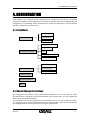
2.1. Part Name
2.1.1. Front Panel
VIDEO STABILIZER
1
○
STATUS
SET
RESET
2
○
3
○
4
○
5
○
① Status LED
This LED is located on the left side of the front panel and indicates certain system information.
Device Status
LED Indicator
Power off
Off
In booting
Yellow On (Sometimes “Red On” for a short time)
Not stabilizing
Green Blinking 1Hz
Stabilizing
Green On
Malfunction
Red Blinking 1Hz
② Reset
The reset switch is used for resetting device to Factory Default settings. Refer to section “4.7.
Restore Defaults” for more specific information.
③ Down Button
Navigate through menus on the screen.
④ Up Button
Navigate through menus on the screen.
⑤ SET Button
Opens the setup menu or select and confirm the input.
01A.03
6
ZS-STB1000 User's manual
2.1.2. Back Panel
DC12V
Vin
Vout
6
○
7
○
Ethernet
8
○
9
○
⑥ Video Input BNC connector
The video input connector, connect to the camera.
⑦ Video Output BNC connector
The video output connector, connect to a device such as a VCR or monitor.
⑧ LAN Connector (Ethernet)
This is a RJ45 LAN connector for management.
⑨ Power Adaptor Connector (DC 12V)
The device needs a DC 12V adapter for power supply.
01A.03
7
ZS-STB1000 User's manual
3. CONNECTION
3.1. Connectors
Video In
Video Out
LAN
DC 12V
The video stabilizer is intended to be connected in-line between the video source and the
video display.
Connect the power to the unit with the supplied power adaptor. Your video stabilizer should
now be operational and stabilizing video. There is no need to perform any other set up.
In the event of a power failure to the video stabilizer unit, the video will pass through the unit
un-stabilized.
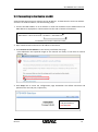
The Ethernet connection is only for firmware update. (Refer to section “5.3.2. How to Update
the ”). It can also be used to control advanced configuration parameters (Refer to section ”4.
CONFIGURATION 오류! 참조 원본을 찾을 수 없습니다. “) but is not required to get started.
i
Note
01A.03
The stabilizer takes about 1 minute to start operating. During the start-up
time the stabilizer remains in loop-through mode.
8
ZS-STB1000 User's manual
4. CONFIGURATION
Your stabilizer unit is shipped with the default options configured at the factory. The default
options are suitable for most applications, but some installations may warrant slightly different
configuration. The following section details how to change the parameters from the default
settings, and the effect that they have.
4.1. Setup Menu
STABILIZATION
BASIC SETTINGS
VIDEO OUTPUT
BORDER IN-FILL
FREQUENCY RESPONSE
AUTO DISABLE
ADVANCED SETTINGS
OSD
MAX HORIZONTAL SHIFT
MAX VERTICAL SHIFT
VIDEO STANDARD
VIDEO SETTINGS
COLOR SETTINGS
DELAY SETTINGS
PRODUCT INFO
RESTORE DEFAULTS
EXIT
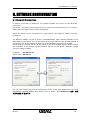
4.2. How to Change the Settings
The configuration parameters can be controlled by the buttons on the front panel. To access
the SETUP menu on the device, press the SET button on the front panel. You can navigate the
menus using the Up/Down buttons.
The parameters can also be configured by connecting the unit to a PC (via an Ethernet switch,
or a crossover cable), and accessing the device from a web browser. Most of the functions on
the webpage work the same as the ones on the front panel button.
01A.03
9
ZS-STB1000 User's manual
4.3. Basic Settings
4.3.1. Stabilization Mode
The stabilization mode has 2 options:
On:
Off:
[Default] Stabilization is enabled.
Stabilization is disabled (video pass through).
4.3.2. Video Output
The video output mode has 2 options:
Full Screen
[Default] The output signal is the full-screen stabilized version of the
input signal.
The output signal consists of 50% un-stabilized, and 50% stabilized
versions of the input signal, split vertically down the middle of the
output. This mode is primarily used for demonstrating the
effectiveness of the stabilization unit on a single monitor and would
not normally be used in day-to-day operation.
Split Screen
Full Screen Mode
Split Screen Mode
<un-stabilized video> <stabilized video>
4.3.3. Border In-fill
In order to keep the output frames steady and aligned to a reference frame, the output frames
are shifted with respect to the input frames. As the camera moves around, so the output
frames are shifted to keep the image features aligned to previous frames. This results in areas
for which there is no image data available:
Image Movement
Camera Movement
No Image Data
The Border In-fill mode controls what happens to those areas that do not contain any image
data. There are 4 options available:
01A.03
10
ZS-STB1000 User's manual
Fast Fade
Slow Fade
No Fade
Fixed
None
[Default] Newer frames are composited on top of older frames. The old
frames are faded away to black quickly (see diagram). This mode is most
suited to PTZ and fixed cameras.
Newer frames are composited on top of older frames. The old frames are
faded away to black slowly (see diagram).
Newer frames are composited on top of older frames. The old frames are not
faded away (see diagram). Suitable for fixed cameras where there is minimal
movement by people and cars around the edge of the scene.
A fixed size black border is present on all sides which blanks out the moving
edges of the image (see diagram). The size of the borders is equal to the
maximum frame shift. See Advanced Configuration.
Old frames are not displayed. Regions of the output image for which there is
no available data are filled with black (see diagram).
Fast/Slow Fade
No Fade
Fixed
None
01A.03
11
ZS-STB1000 User's manual
4.4. Advanced Settings
4.4.1. Frequency Response
The Frequency response Mode has 2 options:
Normal
[Default] The stabilization algorithm parameters are
optimized to give the best stabilization results for the
normal frequency movements.
Low Frequency (<1Hz):
This stabilization mode is designed to allow tracking of
intentional camera panning by not stabilizing low
frequency movements (< 1Hz). The Low Frequency mode
has a lower cut-off frequency to allow better low frequency
stabilization at the expense of worse tracking of intentional
movement (see Attenuation vs Frequency graph on the last
page). This mode will automatically switch to the higher
frequency mode when excessive movement in one
direction is detected in order to allow better tracking of
intentional movement. Once this movement has stopped it
will revert back to the low frequency mode.
4.4.2. Auto Disable
There are 2 options for Auto Disable - neither is selected by default:
Pan/Tilt
This option disables the stabilization when excessive pan or tilt motion is
detected. This makes it easier to control pan/tilt cameras because the Stabilizer
ceases to oppose operator pan/tilt commands above the threshold. Once
panning stops, there is a 3 sec timeout period before stabilization is reactivated.
Low Detail When this option is enabled, the algorithm is disabled when a scene with
insufficient detail for reliable stabilization is detected. This prevents the image
position ‘hunting’ when there is very little scene detail or features. For example,
when the camera is pointed at a completely blank wall the stabilized image will
jump around slightly because it is locking on to the random video noise. Similar
hunting problems can occur in other situations where a large part of the scene
lacks suitable detail for Stabilizer lock:
i
Note
01A.03
Other low contrast situations such as at night scenes.
Scenes with an absence of detail in one direction such as venetian blinds.
Scenes with a repeated pattern such as a brick wall.
Enabling the Low Detail mode can result in the stabilization being disabled
prematurely on low contrast or noisy video, which is why this mode is not
enabled by default.
12
ZS-STB1000 User's manual
4.4.3. On-Screen Annotation
When this option is enabled, a message will appear on the screen whenever stabilization is
disabled. It is not intended that On-Screen Annotation is permanently enabled. Generally, it
should be used to help set up the Stabilizer in the following configuration situations:
To see the effect of the Auto Disable pan/tilt and Auto Disable Low Detail functions.
To see if the stabilization is being disabled because the camera motion is too fast.
4.4.4. Maximum Frame Shift
This is the maximum amount in image pixels that the algorithm will shift the frame horizontally
and vertically in either direction from the normal position. Both horizontal and vertical shifts
are settable in the range [24 – 256], the default is 128.
Usually the only reason to select low Frame Shift values is when the Border In-Fill is in Fixed
mode because as the borders are increased in size the viewable image area gets smaller by the
same amount.
!
Caution
01A.03
Setting these values too low will prevent the algorithm from stabilizing
properly. The lower the setting the less stabilization range is possible.
13
ZS-STB1000 User's manual
4.5. Video Settings
4.5.1. Video Standard
Select between NTSC and PAL video standards.
4.5.2. Color Settings
Change the Brightness, Contrast, Hue, Saturation and Sharpness of the video.
4.5.3. Delay Settings
Change the vertical and horizontal capture delay of the video. These settings affect the vertical
and horizontal position of the displayed image, allowing the black borders to be equalized on
either side and top and bottom of the image. (This adjustment may be necessary because
some analogue video signals do not conform exactly to the blanking timing of the video
standard and consequently a black stripe may be visible on one side of the image.)
i
Note
Set Border in-fill to ‘none’ when adjusting the Delay Settings so that the effect
of the horizontal and vertical delay can be seen clearly.
4.6. Product Info
Display the Product information as below.
IP Address
Subnet
MAC Address
Serial number
Firmware version
4.7. Restore Defaults
Restore the configuration to the default values except the network configuration of the device.
If you want to restore the configuration including the network settings, you need to do the
factory default setting by using the reset button.
- Reset to Factory Default Settings
1. Disconnect the power supply from the device.
2. Connect the power to the device with the Reset button pressed and held.
3. Release the Reset button after 5 seconds.
4. Wait for the system to reboot.
01A.03
14
ZS-STB1000 User's manual
The factory default settings can be inferred as follows:
IP address:
Network mask:
Gateway:
User ID:
Password:
01A.03
192.168.xx.yy
255.255.0.0
192.168.0.1
root
pass
15
ZS-STB1000 User's manual
5. NETWORK CONFIGURATION
5.1. Network Connection
A network connection is needed for the firmware update and control of the advanced
parameters.
The device is accessed by connecting the unit to a PC (via an Ethernet switch, or a crossover
cable), and accessing the device from a web browser.
Before the device can be accessed from a web browser, the default IP address must be
established.
The default IP address of your IP device is 192.168.XXX.XXX, where XXX.XXX depends on the
MAC address of the device. You can determine the correct IP address from the MAC address of
your device. You can also find the IP address from the PRODUCT INFO menu on the OSD.
Please make sure that the device and your PC are on the same network segment before running
the installation. If the network segment between your PC and the device is different, change
your PC’s settings as below.
IP address : 192.168.xxx.xxx
Subnet mask: 255.255.0.0
You can also change the network configuration of the device with IPAdminTool. For more
information regarding IPAdminTool, please refer to section ”5.3. IPAdminTool”오류! 참조
원본을 찾을 수 없습니다..
01A.03
16
ZS-STB1000 User's manual
5.2. Connecting to the Device via LAN
View the web page using your IP device and its IP address. To determine the correct IP address
and use it to access the device, use the following steps:
1. Convert the MAC address to an IP address or check the IP address on the IPAdminTool. The
MAC address is displayed on a label attached on the side or bottom of the device.
MAC address = 00-13-23-01-14-B1 → IP address = 192.168.20.177
Convert the Hexadecimal number to Decimal number.
2. Open a web browser and enter the IP address of the device.
3. Click Continue to this website on the Security Certificate Alert page.
(The explanation and captured images at this manual are mainly on the basis of Internet
Explorer 7.0)
4. Click Setup link to access the configuration page. Remember the default username and
password are root and pass, respectively.
The default username
and password are:
root and pass.
01A.03
17
ZS-STB1000 User's manual
5.3. IPAdminTool
IPAdminTool automatically searches all activated devices and shows the IP address, MAC
address and other relevant information. You can change the network configuration and update
the device’s firmware with this tool. IPAdminTool is provided with the SDK in the following SDK
path.
{SDK root}\BIN\TOOLS\AdminTool\
5.3.1. How to Manage the Network Settings
You can adjust the network settings with IPAdminTool. Go to IP Setup button on the upper
menu bar or you can use the shortcut menus as well.
DHCP
Let the DHCP server get the IP address automatically.
Static
Set the IP address, Subnet Mask, Gateway and DNS manually according to users’ network
requirements.
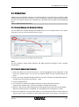
5.3.2. How to Update the Firmware
1. Select the device you want from the list: it will be highlighted in blue. Right-click it and
select the ‘Update’ menu. You can see the window below and the selected devices are
listed.
2. Now, if you have completed listing the devices you want to update, click the Browse button
and select the firmware file (File format : *.pkt).
3. Click the Update button.
4. It is necessary to authenticate against the device. Type the ID and password of
administrator authentication. The factory default is root(ID) and pass(pw).
5. Wait for a few seconds and the progress bar will indicate the current status of the update.
When the update process is completed, the ‘All update finish’ message box is shown.
6. After the completion of the firmware update, you should wait for about 1 minute while the
device restarts. After completion of the update and reboot of the system, if the device is
01A.03
18
ZS-STB1000 User's manual
not shown on the scanned list of IPAdminTool, click the ‘Refresh’ button or try to type the
IP address in Internet Explorer’s address bar.
01A.03
19
ZS-STB1000 User's manual
APPENDIX (A): SPECIFICATION
Summary
Stabilization
Stabilization tracking rate
Stabilization range
Stabilization frequency
Video delay
Stabilization
Automatic algorithm
Border
Lock-on time
Video
Video Input
Video Output
Video standards
Video loop-through
D1 resolution digitization
Function
Plug and Play
Start-up time
Configuration
Network
Environmental
Operating Temperature
Operating Humidity
Electrical
Power Source
Power over Ethernet
Power consumption
Mechanical
Dimension
Weight (Approx)
01A.03
Approx ±3000 pixels/sec.
Variable up to ±256 pixels
0.1-30Hz (see graph*)
< 80 ms.
X-Y movement at sub-pixel accuracy.
Locks on to background features.
Ignores moving objects and burnt-in text
Image in-fill. Removes distracting image border movement by
using in-filling data from previous frames.
< 80ms from change of image.
Composite, BNC connector.
Composite, BNC connector.
PAL/NTSC selectable
Automatic loop-through when power is off and during start-up
720 x 576 PAL, 720 x 480 NTSC
Works straight out of the box. Simply connect it in- line between
camera & monitor
About 1 minute – Stabilizer remains in loop-through mode while
the Linux Operating System starts
Web browser interface for configuration of advanced modes
Ethernet 10/100 Mbps (For firmware Update & Remote Set up)
0 ℃ ~ 60 ℃ (32 ℉ ~ 140 ℉)
Up to 85% RH (Non-condensing)
12V DC (DC Jack)
Not Available
260mA @ +12V
103(W) x 38(H) x 142(D) mm
430g
20
ZS-STB1000 User's manual
Frequency Response Graph
01A.03
21
ZS-STB1000 User's manual
APPENDIX (B): DIMENSION
(Unit: mm)
01A.03
22
ZS-STB1000 User's manual
APPENDIX (C): TROUBLE SHOOTING
Checking your Firmware
Firmware is software that determines the functionality of the device. One of your first actions
when troubleshooting a problem should be to check the currently installed version. The latest
version may contain a correction that fixes your particular problem. The current firmware
version in your device can be seen in PRODUCT INFO on the OSD or Main menu on the
webpage.
New firmware can be downloaded from the FTP site. When you download firmware from the
FTP, your product will receive the latest available functionality. Always read the upgrade
instructions and release notes available with each new release, before updating the firmware.
Please contact us to get an FTP account.
Support
If you cannot resolve an issue, for additional assistance please contact your supplier or system
integrator or go direct to our Technical Support Team.
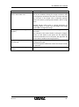
Troubleshooting
Problem
Solution
The video output is not stabilized This is quite normal – the unit remains in loop-through
for about 1 minute after mode while the internal Linux Operating System bootsconnecting the power supply.
up. The loop-through mode ensures that no video loss is
incurred during this time.
The video is not synchronizing
Make sure the correct video standard is selected (NTSC
or PAL) on the Video Settings page of the Web browser
interface.
Sometimes the image jumps about The stabilizer cannot find any features in the image to
and does not ‘lock on properly’
lock on to or the features repeat (brick wall) or lack detail
in a particular direction (venetian blinds).
Stabilization can be suppressed in these cases by
selecting the Auto Disable – Low Detail option on the
Advanced Configuration page.
The stabilization is not very good The default stabilization algorithm does not suppress
with slow camera sway
slow movement to allow tracking of intentional PTZ
(Pan/Tilt/Zoom) movements. (See frequency response
graph in the specification).
Selecting ‘Slow Stabilization’ mode in the Camera
Installation settings on the Advanced Configuration page
will improve low frequency stabilization but will make
01A.03
23
ZS-STB1000 User's manual
PTZ tracking performance worse.
Sometimes incorrect data can be When border infill is enabled, blank areas of the image
seen in the border area
left by the stabilizer shifting the image are filled in with
old image data. Sometimes this does not match well with
the live part of the image. This is especially apparent
when the camera is panning and old data is left for a long
time.
Disable border infill if this is causing distraction by
selecting ‘None’ or ‘Fixed’ from the Border Infill setting
on the Basic Configuration page.
The image is not being stabilized Make sure the Maximum Frame Shift settings are not set
properly
too small.
For example, if the camera shake is causing the image to
move up and down by 50 pixels but the Maximum
Vertical Frame Shift is set to 32 pixels, the algorithm will
not be able to stabilize the image properly.
The picture jumps around during Try enabling Auto Disable – Pan/Tilt on the Advanced
fast panning
Configuration page.
This will suppress stabilization when fast Pan/Tilt motion
is detected.
The unit is exhibiting strange Try restoring the factory defaults.
behavior
01A.03
24
ZS-STB1000 User's manual
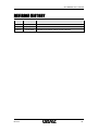
REVISION HISTORY
MAN#
DATE(M/D/Y)
01A.01
12/11/2009
Created
01A.02
11/09/2010
Reviewed
01A.03
12/22/2010
Modified information about the LED indicator
01A.03
Comments
25