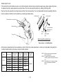
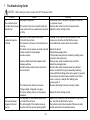
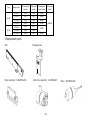
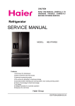
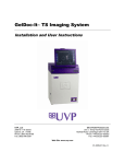
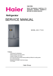
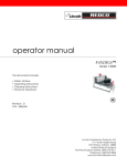
1
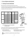
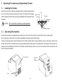
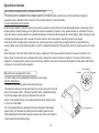
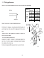
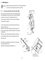
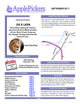
Automatic Screw Feeder
自動ネジ供給機
QUICHER
Series
NJ²
NSRI
Type
Operation manual (Maintenance)
・Read these instructions for the proper use of this machine.
・After having read these instructions, keep them in a convenient
place so you or the operator can refer to them whenever necessary.
ATTENTION : www.ohtake-root.co.jp is the only web site associated with our company.
We do not have any branches in China.
www.ohtake-root.co.jp
www.ohtake-root.co.jp
HP
NJ2MA01M
Contents
1. Before Use ・・・・・・・・・・・・・・・・・・・・・・・・・・・・・・・・・・・・・・ 1
2. Operating Precautions ・・・・・・・・・・・・・・・・・・・・・・・・・・・ 1
3. Component Names ・・・・・・・・・・・・・・・・・・・・・・・・・・・・・・ 3
4. Pre-operational Checks and Adjustments ・・・・・・・・・ 4
6. Maintenance ・・・・・・・・・・・・・・・・・・・・・・・ 13
7. Troubleshooting Guide ・・・・・・・・・・・・・ 16
5.Operating Procedures and Operational Checks ・・・ 9
10. External dimension ・・・・・・・・・・・・・・・・・ 22
8. Main Specifications ・・・・・・・・・・・・・・・・・ 19
9. Warranty ・・・・・・・・・・・・・・・・・・・・・・・・・・・ 21
1. Before Use
Thank you for purchasing the NJ 2 Series Automatic Screw Feeder. Before using this machine, make sure that the following accessories are supplied with the machine.
Accessories
Instruction manual x 1
AC adapter x 1
Allen wrench x 1
Screwdriver x 1
To obtain the optimum performance from this machine, it is essential that you thoroughly read this manual.
2. Operating Precautions
Installation
Install this machine at a level, steady place.
CAUTION If you install this machine in an unstable location, it may topple or fall, causing personal injury.
Do not operate this machine in places where flammable or explosive gas exists or with high humidity.
CAUTION Using this machine in such locations will create a safety hazard.
When shutting down this machine at the end of day or leaving it unused for long periods of time
CAUTION
When shutting down this machine at the end of day or, leaving it unused for long periods of time, disconnect its
AC adapter from the power outlet.
-1-
AC adapter
the AC adapter attached only.
Use
CAUTION
Rail
Do not scratch the rail. Do not apply any oil or grease to the rail.
Incompatible screws
Use specified screws only. Avoid using screws to which oil, grease, dirt, or other foreign matter is attached.
Screw access precautions
When picking up screws, exercise care not to apply any undue force or shock.
Avoid foreign objects
Do not position your fingers or foreign objects in the screw bin, holes, or other open spaces as it may cause
CAUTION
personal injury. Be sure that no inappropriate screws or foreign objects is dropped into this machine.
Abnormalities during operation
If any abnormality or troubles occur during operation, turn off the power switch and disconnect the AC adapter from
CAUTION
outlet.
power
If you continue to operate the feeder while it is acting abnormally, a risk of fire, electric shock, or personal
injury may occur. If you encounter any abnormality, contact your local dealer.
Do not make attempt to repair, disassemble, or modify this machine
CAUTION When this machine is in need of repair, contact your local dealer.
-2-
3. Component Names
Screw bin lid
Rail front-rear position lock
screw access hole
Shutter (in front of
screw passage plate)
Passage plate
Bit guide assembly
Screw passage
window
Bin scooper
plate
Holding plate
(Screw guide1)
Bit guide
Sensor
Power switch
Passage plate lock screw
Screw bin
Bin scooper
plate
Brush
Timing shaft
Rail assembly
Timer setting control
Tilt lock screws
External output jack
-3-
DC jack
4. Checks and Adjustments before Operation
4-1. Confirming the machine’s Model Number
Before using this machine, verify that the model matches the screw size to be used.
To confirm the model number, note the labels attached to the rail assembly . The identification label marking is in R** form.
This machine can be converted to different screw sizes by replacing the rail assembly, and the passage plate. When you replace
component parts, verify the actual screw size to be used.
Type
NJ2-23
Model number
Screw nominal
diameter
Rail model
number
Passage plate
model number
NJ2-2320
φ2.0
R20
W2320
2
φ2.3
R23
W2323
2
φ2.6
R26
W2326
2
φ3.0
R30
W2330
2
NJ -4535
φ3.5
R35
NJ2-4540
φ4.0
R40
NJ2-4550
φ5.0
R50
NJ -2323
NJ -2326
NJ -2330
NJ2-45
W4540
W4550
NOTE: Replacement rails, escapers, and passage plates
are available as options.)
Rail label
Rail assembly
This machine is factory adjusted for pan-head screws prior to shipment. If readjustments are needed to match the screw
applied, complete the following check/adjustment procedures before using this machine.
-Checking and adjusting the brush
-Checking and adjusting the holding plate (screw guide 1)
-Checking and adjusting the passage plate
-Checking and adjusting the rail assembly
CAUTION Before performing any adjustment procedures, please turn off the power
-4-
4- 2. Checking and Adjusting the Brush
Turn off the power switch before performing any
check/adjustment procedure. The switch shown
below is in the off position.
Check the height of the brush. Ensure that the brush check/
adjustment procedure is completed while the brush is placed in
a horizontal position as shown at right. To place the brush in a
horizontal position, rotate the timing shaft with the Allen wrench
supplied with the machine.
Please prepare the screws to be used. Drop a few of them into
the rail groove, check and adjust the brush height as directed
below.
After the brush is placed in a horizontal position as shown on
right, rotate the brush. Adjust height of the brush, so that the gap
between tip of the brush and screw heads is approximately 0 mm.
Brush
Brush mounting
screws
If any adjustment is needed, perform the following procedure:
Loosen the brush mounting screws.
Make adjustments so that the tip of the brush is slightly touchingscrew heads. In this instance, avoid lowering the brush too much.
At completion of adjustment, tighten the brush mounting screws.
Timing shaft
Please make sure that the gap between tip of the brush
and employed screw heads is about 0 mm.
(slightly touching)
After the brush is properly adjusted, rotate it again to verify that it
smoothly moves without any obstruction.
Employed screws
-5-
4- 3. Checking and Adjusting the Passage Plate
Drop few screws into the rail groove. Slide the screws to the passage
window section and check or adjust the passage plate height. Check that the
Passage plate
clearance between the passage window upper end and the screw heads is not
greater than about 0.5 mm and that the screws can pass the passage window.
Brush
If the above requirements are not met, repeat above adjustment
procedures as needed.
After adjustment is completed, tighten the passage plate retaining screw. If the
Employed
screw
screw applied has a relatively short shank, fine adjustments may be needed. For
screws having a relatively long shank, however, coarse adjustments will suffice.
Passage plate retaining screw
Up-down
adjustment
Passage plate
Approx.
0.5mm or less
Employed
screw
Rail
Rail
Bit guide assembly
Holding plate(screw guide1)
4- 4. Checking and Adjusting the Holding Plate (Screw Guide 1)
Drop 5 to 10 applied screws into the rail groove.
Tilt the machine or operate it so that the screws are delivered to the rail assembly
stopper.
If the shutter is closed or there is no clearance between the holding plate
(screw guide 1) and screw heads, the screws will not be able to move. The
screws can go through when the shutter is open with an adequate clearance
provided between the holding plate (screw guide 1) and screw heads.
When the clearance is 0 to 1 mm, the holding plate (screw guide 1) height needs
no further adjustment.
NOTE: If the rail stopper captures a screw and brings the vibration to a stop
immediately, adjust the timer setting control on the rear side of the unit.
-6-
Holding plate (screw guide 1)
Stopper
Bit guide
Approx. 0 to 1mm
Rail
Employed screws
If the holding plate (screw guide 1) height needs to be adjusted, proceed as directed below.
Tilt this machine or operate it so that the screws are delivered to the rail assembly stopper. If there is no clearance between the holding plate (screw guide 1) and screw heads, the screws cannot move. The screws can move while the shutter is open with an
adequate clearance provided between the holding plate (screw guide 1) and screw heads.
If the screws do not move to the escaper section, loosen the bit guide assembly retaining screw, and rotate the bit guide assembly
up-down adjustment screw counterclockwise with the accessory Allen wrench to move the holding plate (screw guide 1) upward.
Bit guide assembly height
Adjust the holding plate (screw guide 1) height by rotating the bit guide assembly height
adjustment screw
adjustment screw to provide a clearance of 0 to 1 mm between the holding plate
Clockwise rotation → Descent
(screw guide 1) and the head of the screws.
Counterclockwise → Ascent
Stopper
When performing the above adjustment procedure, make sure that the gap between
the holding plate (screw guide 1) and rail is uniform. Please make sure that the gaps
between the holding plate and the rail are the same on the rear end and the front end. Bit guide assembly
After completion of adjustment, be sure to tighten the bit guide assembly
retaining screw.
If the employed screw has a relatively short shank, fine adjustments are needed.
For screws having a relatively long shank, however, coarse adjustments will suffice.
Holding plate
(Screw guide1)
4- 5. Checking and Adjusting the Rail Assembly
Check the position of the stopper and sensor.
・Ensure that the rail is fixed so that "A" portion of the stopper is
0mm to 0.5mm ahead of the sensor optical axis.
・If adjustment is necessary, adjust it front and rear by loosening
the rail front-rear position lock screw
Bit guide assembly retaining screw
Rail front-rear position lock
screw access hole
A
Sensor optical axis
Rail assembly
-7-
4- 6. Checking and Adjusting the Bit Guide
Place five to ten screws in the rail and tilt this machine until they hit the stopper on the rail
assembly.
When the internal shutter is closed, the screws cannot go through the passage plate.
If it is closed, turn the timing shaft clockwise with the Allen wrench to keep it open.
The stopper is fixed to the rail assembly. The adjustment of the stopper is made by moving
the rail assembly front and rear. If the “V” groove on the bit guide and the rear point of the
Phillips screw head are not aligned, adjust as follows:
Loosen the bit guide mounting screw with the Allen wrench and move the bit guide forward
and back to put them in alignment.
Please remember to tighten the screws after adjusting.
Bit guide mounting screws
Bit guide
V groove
Stopper
Employed
screw
-8-
5. Operating Procedures and Operational Checks
5- 1. Loading the Screws
Open the screw bin lid. While the bin dipper plates are at the lowest position,
pour in the screws until they are piled up to about 3 mm below the rail upper
surface. Make sure that screws are equally distributed into the right-and lefthand bins.
Approx. 3 mm
CAUTION Do not load the screws to excess amount.
Rail
Screw bin
Employed
screws
Bin scooper plates
5- 2. Operating this machine
Connect the accessory AC adapter plug to the DC jack on the rear of this machine, and the other side to a power outlet.
Turn on the main power switch. The lamp incorporated in the power switch will illuminate.
Turning on the power switch causes the drive motor to rotate normally, the bin scooper plates to move up and down, and the rail to
vibrate. After a while, the loaded screws are sequentially transported along the rail and delivered to the stopper. If the screw is not
picked up for an extended period of time, the vibration will automatically come to a stop. At the moment the screw is picked up, this
machine resumes operation.
Timer setting control
Power switch
(lampincorporated)
DC jack
- 9-
Operational features
This machine is equipped with an overload protection circuit.
If a movable part is overloaded during a feeder operation, for instance, when a small screw or other particles is trapped, or
excessive screw is placed into the screw bins, the overload protection circuit will activate.
Function descriptions and remedies
Under normal conditions, the drive motor in this machine rotates in normal direction to feed the loaded screws continuously to the
escaper section, thereby allowing you to obtain the screws successively. However, if any movable section is overloaded, the drive
motor will rotate in reverse direction for a predetermined period of time and then resumes its normal rotation. When the cause of the
overload is eliminated upon motor reversal, the motor reverts to its normal rotation, resuming normal screw supply.
If the cause of the movable section overload is not cleared upon motor reversal, the overload protection circuit performs the
reverse rotation and normal rotation repetition cycle for a predetermined period of time and then shuts off power supply to the drive
motor.
When the power to the drive motor shuts off as above, please turn off the power switch and clear the cause of overload. For instance, when the screw bins are overloaded with screws, reduce the number of screws in the bins. If a screw or other article is
trapped in a movable section, please remove it with tools. After the cause of the overload is eliminated, turn the power switch back
on (power-on reset) and resume operation.
Timer setting
This machine is equipped with a timer.
The timer setting can be adjusted according to the screw type.
Function descriptions
The actual screw feeding speed varies with screw type.
This machine continues running while there is no screw in the screw removal
area of the escaper section. It stops its operation when a predetermined period of time elapses after a screw is retained in the removal
section. This duration of time can be adjusted with the timer setting control
on the rear of the feeder.
It is recommended that you decrease the timer setting when the feeding
speed is high, and increase the setting when the feeding speed is slow.
When adjusting the timer setting, please exercise care and do not rotate the
control beyond its permissible range.
- 10-
Increase
Decrease
Timer setting control
This machine is equipped with an external output signal connector.
The incorporated signal cable enables you to obtain a signal that
indicates whether a screw is present in the escaper section screw
removal area.
[ Function]
When picked screw up
: signal high (ON) approx. 0.2sec
Incoming current
: shall be limited to less than 100mA
CAUTION : Additional resistor is required on external
circuit for regulating current
[Capacity]
MAX DC current : 100mA
External supply voltage : 5 to 24VDC (max27VDC)
[CAUTION]
Please use φ3.5-3mm micro-type single plugs.
Recommended type : Marushi electric Mfg.
MP-019LC(Straight type)
MP-012LN(Right angle type)
Recommended connector cable : Marushi electric Mfg.
SC420S-2M-RS
External output jack
Example
Inside
Outside
This machine is equipped with a tilting mechanism
When the screw feeding speed is too slow, you can install this machine in a tilted
position.
Descriptions
Loosen the tilt lock screws.
Pull out the base bracket from the rear of the feeder and fix it in an
appropriate position.
After this machine is tilted, make sure that it is steady.
Please do not tilt this machine beyond the capacity of its tilt mechanism.
- 11-
A tilt of up to
about 12 mm can
be provided.
Base bracket
Tilt lock screw
5- 3. Picking up the screw
Attach a bit to your electric screwdriver to match the head of the screw. Refer to the following.
Standard
Bit shape
JIS
small
screw
Phillips head
Notice: The screwdriver bit must be magnetized before use.
Screw normonal Cross size on top
diameter
No.
φ2.0
No.1/No.2
φ2.3
No.1/No.2
φ2.6
No.1/No.2
φ3.0
No.1/No.2
φ3.5
No.1/No.2
φ4.0
No.2
φ5.0
No.2
Electric driver
Put the driver bit somewhere above the opening of the bit guide, and
push it straight down while turning the bit slightly, until it hits the screw
head.
Vibration of the rail shall stop when the screwdriver bit reaches the
bottom of the screw head slot.
Then pull the screw out towards yourself.
Be careful not to push the screwdriver bit into the screw head with too
much force. If the driver is lowered into the screw head with moderate
force, vibration of the rail shall stop.
Do not use more pressure than necessary to stop movement of the rail.
- 12-
①
Bit guide
Employed screw
②
6. Maintenance
CAUTION Before performing any maintenance, turn off the power switch
and remove all the loaded screws from this machine.
6- 1. Cleaning the Rail and Rail Guide Wall
Rail front-rear position
lock screw
When the rail groove becomes dirty, the screw feeding speed
may be affected. If such situation occurs, wipe the rail groove
clean with a thin, clean cloth moistened with alcohol.
If the rail groove is heavily soiled, remove the rail assembly
and then perform cleaning.
Loosen the rail position lock screw and then pull the rail assembly forward and out.
With a thin, clean cloth moistened with alcohol, wipe clean
the rail groove and upper and lateral surfaces of the removed
rail assembly.
With a thin, clean cloth moistened with alcohol, wipe clean
the rail guide wall surface, which is revealed upon rail assembly removal.
After cleaning, reassemble the rail section by reversing the
removal procedures above.
Adjust the rail assembly position.(Refer to 4-5)
Pull out
the rail assembly
Rail lateral
surface
Rail groove
Rail upper
surface
Rail assembly
Rail guide wall surface
(guide surface revealed
upon rail assembly removal)
- 13-
6- 2 Replacement Procedures
●Replacing the rail assembly
The rail assembly of this machine can easily be replaced.
If the loaded screws do not smoothly feed after cleaning or if you intend to use a
different screw diameter, replace the rail assembly.
For the replacement procedure, see the earlier section on cleaning.
●Replacing the passage plate
This machine allows you to change the screw diameter setup by replacing
associated components.
(this change can be made with the same OHTAKE feeder machine).
To change the screw diameter, you have to replace the passage plate in addition
to the rail assembly.
To replace the passage plate, remove its retaining screw.
Replace the passage plate in such a manner that the brush is horizontally positioned as shown at right.
Exercise care not to lose the retaining screw.
- 14-
Passage plate
Passage plate
retaining screw
●Replacing the brush
If the ends of the brush bristles are worn out so that improperly oriented screws cannot be swept away, please replace the brush.
To replace the brush, please position it as shown below. You can also adjust its position by rotating the timing shaft.
Remove the brush assembly mounting screws and then the brush assembly. You can disassemble the brush assembly. After the
brush is replaced, install the brush assembly by reversing preceding steps.
Brush bracket 2
Brush
Brush bracket 1
Brush assembly mounting screws
Brush assembly
Washer
M2.6
Timing shaft
Hex socket head
machine screw
M2.6x10
Spring washer
M2.6
Brush assembly exploded view
Parts number : NJ02005a #02
All the above replacement parts are available as options. When they need replacement, contact your local dealer and specify the
machine model number, part names, and part model numbers.
Type
Screw nominal
diameter
Rail model
number
Passage plate
model number
NJ -2320
φ2.0
R20
W2320
NJ2-2323
φ2.3
R23
W2323
NJ2-2326
φ2.6
R26
W2326
NJ2-2330
φ3.0
R30
W2330
NJ2-4535
φ3.5
R35
NJ2-4540
φ4.0
R40
NJ2-4550
φ5.0
R50
Model number
2
NJ2-23
NJ2-45
Brush model
number
NJB0400
W4540
W4550
- 15-
NOTE 1: Different screw sizes may be applicable
with exchanging parts.
NOTE 2: To change the screw size (nominal
diameter), replace all the parts indicated at
left.
NOTE 3: The replacement rails, escapers, passage
plates, and brushes are available as
options.
7. Troubleshooting Guide
CAUTION
Before taking any action, please turn OFF the power switch.
Cause
Problem
-No power is supplied.
7-1
The machine does
not start when power -The screw in the removal section has not
switched on.
been removed for a predetermined period
of time.
7-2
Loaded screws do
not feed.
-Diameter of the loaded screw does
not match the rail size.
-The number of screws in the screw bins is
too low.
-The brush cannot sweep an oddly oriented
screw away from the passage
window section.
-A screw shank has been trapped in the
passage window.
-An abnormally oriented screw is stuck in
the rail section.
7-3
A screw has been
trapped in the rail
groove.
-The rail does not vibrate (a screw or
foreign object is trapped in a gap).
-The timer setting control is not properly
adjusted.
-The diameter of the loaded screw does
not match the rail size.
-The total length of the loaded screw is
less than the rail groove opening width.
- 16-
Remedy
-Ensure that the AC adapter is properly connected
to a power source.
-Remove the screw from the removal section.
Adjust the timer setting control.
-Change to the machine that is suitable for the
screw size. Use the rail that fits the screw.
-Load additional screws into the screw bins.
-Adjust the brush.
Adjust the passage plate.
The problem may also be cleared by adding some
screws to the screw bins
-Remove any oddly oriented screw and then
adjust the passage plate.
-Remove the oddly oriented screw as indicated
below. Loosen the bit guide assembly retaining
screw,shift the holding plate (screw guide 1) upward,
and remove the abnormally oriented screw. After
screw removal, readjust the holding plate
(screw guide 1).
-Remove the trapped screw or foreign matter.
-Adjust the timer setting control.
-Switch to the machine that is suitable for the screw
size. Use the rail that fits the screw.
-the problem cannot be remedied. Please consider
another automatic screw feeder series.
Problem
7-4
The screws on the
rail do not feed
smoothly.
Cause
-The clearance between the holding plate
(screw guide 1) and screw heads is
insufficient.
-Dirt, oil, or grease is attached to the rail.
-The rail fails to vibrate due to a screw or
foreign object trapped in the opening.
Remedy
-Shift the holding plate (screw guide 1) upward.
Use the Quicher in a tilted position.
Adjust the timer setting control.
-Clean the rail and rail guide.
-Remove the trapped screw or foreign object and then
clean the rail and rail guide.
7-5
Oddly oriented
screws occasionally
travel through the
passage window.
A screw shank easily
gets caught in the
passage window.
-The passage plate is improperly adjusted.
-The employed passage plate does not
match the applied screw.
-The forward-descending tilt of the machine
is
above the permissible limit.
-Readjust the passage plate.
-Use the passage plate that matches the applied screw.
7-6
Screws are not
transported to the
removal section.
-Screws are stopped in the middle of the
rail section.
-Screws are not smoothly delivered from
the rail to the front stopper.
-Readjust the holding plate (screw guide 1).
7-7
The bit doesn't
match the Pillips
head.
-The rail assembly is improperly adjusted.
-The bit guide is improperly adjusted.
-Readjust position between the rail and bit guide.
- 17-
-Adjust the tilting angle,make sure it is within the
permissible limit.
-Readjust the passage plate.
Cause
Remedy
Problem
-The overload protection circuit is activated. -Turn the power switch off and then back on.
7-8
If the operation comes to a stop again, the probable
The machine comes
causes are: There are too many screws in the screw
to a sudden stop.
bin.
--> Adjust the number of screws in the screw bins.
A screw or foreign object is trapped in the movable
section.
--> Remove any trapped screw or foreign object.
-Pick up the screw.
-The screw in pick-up section has not
been removed for a long period of time.
-The timer setting control is improperly
7-9
adjusted.
The bin scooping
plates fail to stop
moving when there is
the screw in pick-up
section.
7-10
Screws have been
dropped inside the
machine.
-Readjust the timer setting control.
-Readjust the holding plate (screw guide 1).
-The holding plate (screw guide 1) is
improperly adjusted.
-The front-rear position of the rail is
improperly adjusted.
-Readjust the front-rear position of the rail.
- 18-
8. Main Specifications
Exclusive adapter
(Switching type)
134W X 215D X 139H (mm)
Dimension
Approx.3kgf
Weight
Screw capacity
Accessories
NOTES
-Measure the shank diameter of the screw to be used, and check
whether it matches the rail groove reference dimension.
-Within the range of screw size and length below, there may be
instances of unique screw shape or structure not compatible with the
feeder unit. Please consult the distributor or manufacturer for further
infomation.
-To change the screw size (nominal diameter), replace all the associated
replacement parts.
-The replacement rail, escapers, passage plates, and brushes are
available as options.
-The product design, performance characteristics, and other
specifications are subject to change and improvement without prior
notice.
Input :AC100~240V 50/60Hz
Output :DC15V
150cc
Operation manual x1
AC adapter x1
Allen wrench x1
Screwdriver x1
Screw head shape
Applicable Screw Reference Table
Screw
nominal
diameter
φ2.0
φ2.3
φ2.6
φ3.0
φ3.5
φ4.0
φ5.0
Screwshaft
diameter
(mm)
1.8~2.1
2.1~2.4
2.4~2.7
2.8~3.1
3.3~3.7
3.8~4.3
4.8~5.1
Screwhead
diameter
(mm)
3.0~ 6.8
3.0~ 6.8
3.6~ 6.8
4.0~ 6.8
4.8~10.7
5.4~10.7
6.2~10.7
Screw head
Washer
height
diameter
(mm)
(mm)
3.0~ 9.8 0.5~5.5
3.0~ 9.8 0.5~5.5
3.6~ 9.8 0.5~5.5
4.0~ 9.8 0.5~5.5
4.8~13.2 0.5~8.0
5.4~13.2 0.5~8.0
6.2~13.2 0.5~8.0
Pan head
Screw length
(under head
portion)(mm)
2.6~18
2.9~18
3.2~18
3.6~18
4.1~18
4.6~18
5.6~18
- 19-
Sems
Double
sems
Washer
head
Bind
Flat
Counter
-sunk
Hexagon
flange
bolt
○
○
○
○
○
○
○
○
○
○
○
○
○
○
○
○
○
○
○
○
○
○
○
○
○
○
○
○
○
○
○
○
○
○
○
○
○
○
○
○
○
○
○
○
○
○
○
○
○
Type
NJ2-23
NJ2-45
Model number
Screw nominal
diameter
Rail model
number
Passage plate
model number
NJ2-2320
φ2.0
R20
W2320
NJ2-2323
φ2.3
R23
W2323
NJ2-2326
φ2.6
R26
W2326
NJ2-2330
φ3.0
R30
W2330
NJ2-4535
φ3.5
R35
NJ2-4540
φ4.0
R40
φ5.0
R50
2
NJ -4550
Brush model
number
NJB0400
W4540
W4550
○Replacement parts
Rail
Brush assembly : NJ02005a #02
Passage plate
Motor drive assembly : NJ04500e#01 - 20-
Motor : NJ09582a #05
9. Warranty
For users within Japan, the product is covered by warranty for a period of six months after the date of delivery. Such warranty will not
be applicable to purchase or users outside of Japan. If it should become faulty, however, please contact your local dealer.
Solutions to the following situations may be implemented at a reasonable charge without regard to the warranty period.
-Defects caused by misuse.
-Defects caused by product modifications or unauthorized repairs.
-Defects caused by natural disasters or Acts of God.
-Defects caused by a factor external to the product.
-Cost of replacement of consumable parts (brush and motor) and replacement parts (brush, rail assembly, passage plate, and
escaper) including the cost of such parts.
After production of repair parts is discontinued, they shall be kept available for at least 5 years.
After this period, additional services may be available upon request.
Please consult with your local dealer, or our service center for further information.
- 21-
10.External dimension
External output jack
Timer setting control
Product seal
DC jack
[unit: mm]
- 22-
http://www.ohtake-root.co.jp
岩手県一関市萩荘字金ヶ崎
〒 021-0902
2727
〒021-0902
岩手県一関市萩荘字金ヶ崎
Tel
Tel +81-191-24-3144
0191-24-3144
Fax
+81-191-24-3145
Fax 0191-24-3145
27 Kangasaki
KanegasakiHagisyou
Hagisyou
Ichinoseki
Ichinoseki
Iwate, 021-0902
JAPAN
021-0902 JAPAN
Tel
Tel +81-191-24-3144
+81-191-24-3144
Fax
Fax +81-191-24-3145
+81-191-24-3145
「Quicher」 「OHTAKE」 「OHTAKE ・ ROOT KOGYO」 is a trademark or registerd trademark of OHTAKE ・ ROOT KOGYO CO.,LTD.]
「Quicher( クイッチャー)」 「OHTAKE」 「OHTAKE ・ ROOT KOGYO」 は、 株式会社 大武 ・ ルート工業の商標又は登録商標です。
The specification and the design of a product may be changed without a preliminary announcement for improvement.
改良のため、 予告なくデザイン、 性能、 仕様等を変更することがあります。
Photocopy, reproduction or publication of any part of this user's manual without permission, is strictly prohibited by copyright law.
この取扱説明書の一部または全部の無断転載、 複製を禁じます。
(as of November, 2014)
© Copyright OHTAKE ・ ROOT KOGYO CO.,LTD.
(2014 年 11 月現在 )