1
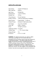
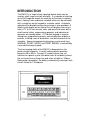
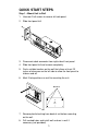
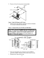
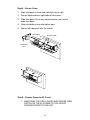
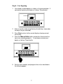
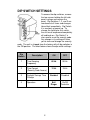
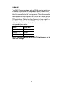
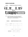
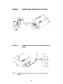
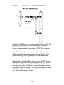
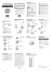
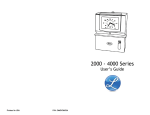
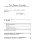
888 534-5994
DWA-S
SONACHRON
USER MANUAL
®
Sonachron (DWA-S)
User’s Manual
TABLE OF CONTENTS
SPECIFICATIONS..................................................... 1
INTRODUCTION ....................................................... 2
QUICK START STEPS.............................................. 3
DIP SWITCH SETTINGS........................................... 8
PROGRAMMING A SECURITY CODE ..................... 9
UNLOCKING THE KEYPAD.................................... 10
SETTING TIME AND DATE .................................... 10
PROGRAMMING EVENTS (On/Off Controller) ...... 11
PROGRAMMING EVENTS (Bell Ringer)................ 12
PROGRAMMING SIGNAL LENGTH (Bell Ringer) .. 12
MANUAL LUNCH AND BREAKS (Bell Ringer) ...... 13
SIGNAL ON/OFF..................................................... 14
MANUAL OPERATION............................................ 14
STANDBY POWER ................................................. 14
RS485...................................................................... 15
WIRING DIAGRAMS ............................................... 16
Limited One-Year Limited Warranty ........................ 24
SPECIFICATIONS
Input Voltage
115 VAC (220 Optional)
Input Frequency
50/60 Hz
Input Power
20 Watts Max
Standby Power
1.2 Ah, 6 V battery
Standby Time
10 Days
Timing Accuracy
Per line frequency
Number of Events
1440 (any combination of weekdays)
Signal Duration
Programmable – 1 to 99 secs
Daylight Savings
Automatic (Disable by dip switch)
Time Display
12 or 24 hr selectable
Comm Port
RS485 – Receiver
Relays
10 Amp Dry Contact
Temperature Range
0 C to 60 C
Voltage Range
+/ - 10 % of input voltage
Shipping Weight
7 lb
Dimensions
9 ¾”x 3 ¼”x 5 3/8”
WARNING: This equipment generates uses and can radiate
radio frequency energy and, if not installed and used in
accordance with the instruction manual, may cause interference
to radio communications. It has been tested and found to
comply with the limits for a Class A computing device pursuant to
Subpart J of Part 15 of FCC Rules, which are designed to
provide reasonable protection against such interference when
operated in a commercial environment. Operation of this
equipment in a residential area is likely to cause interference, in
which case, the user, at his own expense, will be required to take
whatever measures may be required to correct the interference.
1
INTRODUCTION
The DWA-S is a single circuit signaling device which can be
used as a bell ringer or on/off controller. It is capable of retaining
up to 1440 separate events for each day of the week in memory
plus a floating lunch and break schedule which can be activated
with a single key on the keypad or a remote switch. Automatic
adjustment for daylight savings time change is also provided. A
liquid crystal display on the front of the unit displays the current
time (in 12 or 24 hour format), date, and day of the week, bell or
on/off control status, programming prompts, and indication of
operation on standby power. A 24-button keypad is used for
setting time, programming events, manual operation of bells or
controls, initiating lunch or break bells, and on/off control of the
schedule. Access to programming functions and manual keys
(MANUAL, START LUNCH, and START BREAK) is controlled by
a user defined security code.
The time keeping ability of the DWA-S is dependent on the
power source frequency. A switch setting selects operation
based on 50 or 60 Hz. During A.C. power failures, the unit
switches to a quartz crystal time base and a 6 volt battery allows
the unit to continue to keep time and retain all data for 10 days.
Upon power resumption, the battery automatically recharges with
current limited to 1.5 Amperes.
2
QUICK START STEPS
Step 1 – Mount Unit to Wall
1. Unscrew 2 left screws to remove left side panel.
2. Slide front panel left.
3. Disconnect cable connector from right side of front panel.
4. Slide front panel left and remove completely.
5. Find a suitable location on the wall that allows at least 10
inches of clearance on the left side to allow the front panel to
slide on and off.
6. Mark 3 hole positions on wall for mounting the unit.
Mark Holes
7. Remove plastic bushing from back of unit before mounting
on the wall.
8. Drill marked holes and install wall anchors in wall if
necessary (not provided).
3
9. Secure unit to wall using screws (not provided).
Drill Holes
Wall
Anchor
Step 2 – Swith Off Power to AC Circuit
1. SWITCH OFF THE CIRCUIT THAT WILL FEED AC POWER
TO THE UNIT BEFORE PROCEDING.
Step 3 – Connect Wires for 115VAC or 24VAC Bells
IMPORTANT! This unit is shipped from the factory as a Bell
Ringer. To change to an ON/OFF controller, see DIP Switch
Setting on page 8. This section provides instructions for
wiring 115VAC or 24VAC bells, see Wiring Diagrams on
pages 20 – 22 for other options.
1. There are three options for routing wires into the DWA-S:
top, back or bottom. Select on of these and remove the plug.
2. Remove cover from terminal strip.
4
IMPORTANT: DO NOT PROCEED IF WIRE COLORS ARE
DIFFERENT THAN SHOWN OR IF YOU ARE UNSURE
WHICH WIRES ARE AC HOT, AC NEUTRAL AND
GROUND. THERE IS RISK OF PERSONAL INJURY AND
DAMAGE TO THE UNIT THAT’S NOT COVERED BY
WARRANTY. INEXPENSIVE TESTERS ARE AVAILABLE
AT YOUR LOCAL HOME ELECTRICAL SUPPLY STORE
FOR VERIFYING WIRES.
3. Connect wires from power cord as follows: green (ground)
wire to “GND”, white (AC neutral) wire to Line Neutral, and
black (AC Hot) wire to Line Hot.
4. For 115VAC bells or horns, connect a jumper wire between
Line Hot and CKT 1A. Connect the bell wires to AC Neutral
and CKT 1B.
5. For 24VAC bells or horns, connect a jumper wire between
AC Hot and CKT 1A. Connect the transformer
115VAC/primary wires to AC Neutral and CKT 1B. Connect
the transformer 24VAC/secondary wires to the 24 V bells or
horns.
NOTE: See pages 20 - 22 for other wiring options that use
the COM, BREAK and LUNCH terminals.
Step 4 – Turn on Power Switch
1. Press cover onto Terminal Block.
2. Set Power switch to up position.
Replace Cover
Power Switch
5
Step 5 – Secure Cover
1. Align front panel in track and slide half way to right.
2. Secure ribbon cable on right edge of front panel.
3. Slide front panel all the way closed making sure that the
cable lays down.
4. Attach red battery wire onto battery post.
5. Secure left side panel with the screws.
CPU Board
Reconnect Cable
Red Battery
Wire
Step 8 – Restore Power to AC Circuit
1. MAKE SURE THE SIDE COVERS ARE SECURE THEN
SWITCH ON THE AC POWER TO THE CIRCUIT
FEEDING POWER TO THE UNIT.
6
Step 9 – Test Signaling
1. Your display should appear as shown in the picture below. If
not, please contact your dealer or Lathem Time directly.
SECURITY CODE
2. Enter a security code using the day of week keys (remember
the days that you selected).
3. Press Run to return to the normal display showing current
time of day.
4. Press the Manual Bells button and confirm that the bells or
horns are sounding properly. If not, please contact your
dealer or Lathem Time directly.
/
5. Set the time and date, and program the unit as described in
the following pages.
7
DIP SWITCH SETTINGS
To access the dip switches, remove
the two screws holding the left side
panel in place and remove the
panel. Dip Switches 1, 2, and 3 are
monitored at all times and changes
take effect immediately. Dip Switch
4 is read only at power up. To
change the setting for this switch,
the unit must be powered completely
off and back on. Dip Switch 2 is
also used to reset the security code.
Any change in its setting will allow
you to view and change the security
code. The unit is shipped from the factory with all dip switches in
the ON position. The chart below shows the dip switch settings:
Dip
Switch
Description
ON
OFF
1
Time Keeping
Frequency
60 Hz
50 Hz
2
Time Format
(Security Code Access)
12 Hr
24 Hr
3
Daylight Savings Time
Change
Enabled
Disabled
4
Operation
Bell
Ringer
On/Off
Controller
8
PROGRAMMING A SECURITY CODE
Upon power up you are allowed to enter a security code to
restrict access to programming functions. When the unit
displays “SECURITY CODE”, press from one to four Day of the
Week keys. This is your security code. The ERASE EVENT key
can be used to clear the code for re-entry. Press the RUN key to
advance the programming when you are satisfied with the
security code. The unit will prompt “UNSECURED MANUAL
FWD TO CHANGE.” If this selection is chosen, only the
programming functions will require the security code to be
accessed. MANUAL, START LUNCH, and START BREAK will
be unsecured. Pressing the selection requires the security code
to be entered prior to both accessing the programming functions
and using the MANUAL, START LUNCH, and START BREAKS
keys. The remote START LUNCH and START BREAK
switches do not require the security code to activate Lunch or
Break schedules. After choosing the level of security desired,
press the RUN key to advance to the normal display.
If unlimited access to all functions is desired (no security), press
the RUN key without pressing any Day of the Week keys when
the unit prompts for the security code. The unit will advance to
the normal display and no security code will be required to
access any function.
To change or view the security code, remove the left side panel,
toggle Dip Switch 2, and return it to the desired position. The
current security code will be displayed. Replace the side panel.
To change the code, press the ERASE EVENT key to clear the
current code and program the new code in the same manner as
described above. If you do not wish to change the code, press
the RUN key until the normal display returns.
9
UNLOCKING THE KEYPAD
To unlock the keypad, press the Day of the Week keys you
programmed for the security code followed by RUN. The
security keys must be pressed in the exact order as they were
originally entered. The display should read “SELECT
FUNCTION.” To relock the keypad, simply press RUN. The
keypad must be unlocked, or no security programmed, to access
programming functions. Remote operation of Start Lunch or
Start Break switches do not depend on the status of the keypad
or security code. Pressing the MANUAL, START LUNCH, or
START BREAK key while in the programming mode (keypad
unlocked) will ring the bells and return the unit to the normal
display with the keypad secured. The PRGM LUNCH, PRGM
BREAK, SIGNAL LENGTH, and PRGM REVIEW keys may be
pressed while the keypad is locked to view the current settings of
their respective functions.
SETTING TIME AND DATE
Follow procedure above to unlock keypad. The display should
read “SELECT FUNCTION.” To set the time, simply press the
SET TIME key and use the FAST FWD and SLOW FWD keys to
advance to the correct time. The seconds will be set to zero
when either forward key is pressed. Selecting another function
or pressing RUN will start the seconds indexing. To set the
month, date, or year, press the SET MONTH, SET DAY, or SET
YEAR key, respectively. Use the forward keys to advance to the
appropriate setting. Continue to next programming procedure or
press RUN to return to the normal display. The day of the week
will be determined automatically based on the date.
10
PROGRAMMING EVENTS
(On/Off Controller)
With “SELECT FUNCTION” displayed, press the PRGM
EVENTS key. The display should read “CONTROL 12:00 AM.”
Use the FAST FWD and SLOW FWD keys to advance the
displayed time to the desired event time. Once the event time is
reached, press the day of the week keys (Sun, Mon, Tue, etc.)
to indicate on which day(s) the control should operate. Pressing
a key once will display the day of the week and pressing it again
will remove it. The control will default to OFF, press the SIGNAL
ON/OFF key to toggle the control between OFF and ON. Once
you have chosen the day(s) and on/off status for the event, use
the forward keys to advance the time to the next event and enter
the day(s) and On/Off status. Continue in this fashion until all
controls are programmed. Press RUN to lock the keypad and
return to the normal display.
While in the Program Events function, the PRGM REVIEW and
ERASE EVENT keys can be used to scan and erase events,
respectively. To scan programmed events, simply press the
PRGM REVIEW key. The next event in memory will be located
and displayed. Pressing the key repeatedly will scan through all
events sequentially. To erase an event, locate the event and
press the ERASE EVENT key.
PRGM REVIEW may also be used when the keypad is locked.
Pressing the key will display the next scheduled event. Press
the key repeatedly to scan all programmed events. The normal
display will return after 5 seconds or when the RUN key is
pressed. ALL LUNCH and BREAK keys and remote switches
are inactive when using the unit as an On/Off Controller.
11
PROGRAMMING EVENTS
(Bell Ringer)
With “SELECT FUNCTION” displayed, press the PRGM
EVENTS key. The display should read “SIGNAL 12:00 AM” “ON
DAYS:” Use the FAST FWD and SLOW FWD keys to advance
the displayed time to the desired event time. Once the event
time is reached, press the day of the week keys (Sun, Mon, Tue,
etc.) to indicate on which day(s) the bells should ring. Pressing a
key once will display the day of the week and pressing it again
will remove it. Once you have chosen the day(s) for the event,
use the forward keys to advance the time to the next event and
enter the days. Continue in this fashion until all events are
programmed . Press RUN to lock the keypad and return to the
normal display.
While in the Program Events function, the PRGM REVIEW and
ERASE EVENT keys can be used to scan and erase events,
respectively. To scan programmed events, simply press the
PRGM REVIEW key. The next event in memory will be located
and displayed. Pressing the key repeatedly will scan through all
events sequentially. To erase an event, locate the event and
press the ERASE EVENT key.
PRGM REVIEW may also be used when the keypad is locked.
Pressing the key will display the next scheduled event. Press
the key repeatedly to scan all programmed events. The normal
display will return after 5 seconds or when the RUN key is
pressed.
PROGRAMMING SIGNAL LENGTH
(Bell Ringer)
The signal length defaults to 5 seconds. To change this value,
unlock the keypad and press the SIGNAL LENGTH key. The
current signal length will be displayed. Use the FAST FWD and
SLOW FWD keys to change the setting. Values from 1 to 99
seconds are allowed. Press RUN to return to the normal display.
To review the signal length without unlocking the keypad, simply
press the SIGNAL LENGTH key. The normal display will return
after 5 seconds or when the RUN key is pressed.
12
MANUAL LUNCH AND BREAKS
(Bell Ringer)
This function provides a means of programming set lunch and
break lengths which can be initiated at various times during the
day. It is only available when the unit is used as a Bell Ringer
and operating on AC power. Pressing the START LUNCH or
START BREAK key at the keypad (or a remote momentary
switch connected to the unit) causes the bells to signal and a
displayed timer to begin counting down the programmed lunch or
break time. When the timer counts to zero, the bells
automatically signal again to indicate the end of lunch or break.
This feature is especially convenient for facilities which are
serviced by a lunch truck. When the truck arrives on site, simply
press the remote lunch switch to begin the lunch break. This
function also allows a warning bell to ring before the final lunch
or break bell.
To program a lunch, unlock the keypad then press the PRGM
LUNCH key. Use the forward keys to program the desired lunch
length, 00 to 99 minutes. Press the PRGM LUNCH key a
second time to display the length of time (0 to 9 minutes) a
warning bell will ring before the ending bell rings. The default is
0. Use the forward keys to change this value. Press the RUN
key to return to the normal display. Program breaks in the same
method.
Scheduled bells are inhibited during lunch and break periods. If
the schedule is turned off or the MANUAL key pressed while a
lunch or break period is in progress, the remaining lunch or
break time will be canceled. If the wrong key was pressed,
LUNCH instead of BREAK or BREAK instead of LUNCH, simply
press the correct key before the programmed time has expired.
The bells will not ring again and the time already elapsed will be
applied towards the programmed time for the break or lunch. To
review the programmed times without unlocking the keypad,
simply press the PRGM LUNCH or PRGM BREAK key. The
normal display will return after 5 seconds or when the RUN key
is pressed.
13
SIGNAL ON/OFF
Pressing the SIGNAL ON/OFF key when the keypad is unlocked
changes the On/Off status of the programmed schedule. When
the status is ON, bells or controls will operate based on the
schedule. When the status is OFF, the schedule is ignored and
only the manual key will operate the bells or controls. The
current On/Off status of controls will remain active until MANUAL
is pressed or the schedule reactivated. Press RUN to return to
the normal display. When the schedule is inactive, SCHEDULE
OFF will be shown below the time on the display.
MANUAL OPERATION
Pressing the MANUAL key when the unit is being used as a Bell
Ringer will cause the bells to signal for the length of time the key
is pressed. This provides a means of operating the bells at
unscheduled times. Pressing MANUAL while lunch or break is
counting down will operate the bells and cause the remaining
lunch or break time to be canceled.
Pressing the MANUAL key when the unit is operating as on
On/Off Controller will toggle the current On/Off status of the
controls.
The MANUAL key will not ring bells if the unit is operating on
standby power.
STANDBY POWER
During AC power failures, the DWA-S switches to a quartz
crystal time base to maintain the time keeping ability of the unit.
A 6 volt battery allows the unit to continue operation and retain
the programmed schedule for 10 days. An * on the lower line of
the display indicates operation on Standby Power.
Programming, schedule review, and manual toggling of the
On/Off control status are available when operating on battery
back up. If operating as a Bell Ringer, the MANUAL, START
LUNCH, and START BREAK keys, and the remote START
LUNCH and START BREAK switches are inactive during AC
power failures. Schedule operation is also inactive when
operating as a Bell Ringer.
14
RS485
The DWA-S comes equipped with an RS485 receiver which can
be used to synchronize the time and date of the unit with other
equipment. The option supplies three leads on the power supply
board for connecting to the sending device. The interconnection
cable between devices should be a minimum of 3 meters long to
prevent interference to radio communications as required by
FCC regulations. Cables less then 3 meters in length require a
Fair-Rite bead (Lathem Part # VII0058) installed around the
cable. The figure below indicates the signal names and
corresponding wire colors.
Signal
Wire Color
Receive ( + )
White
Receive ( - )
Yellow
Signal Ground
Black
NOTE: Preferred cable is CAT-3 or CAT-5 twisted-pair, up to
4,000 feet in length.
15
WIRING DIAGRAMS
FIGURE 1:
RS-485
DWA-S
DSD
+ -
CONNECTION FOR DWA-S TO LTRX-512
RS-485
DSD
+ -
MODEM
RS-485
DSD
+ -
RS-485
DSD
+ -
1
2
3
TxD
G
N
D
RxD
RS-232
4
5
6
7
8
D
D
+
RS-485
G
N
D
S
Y
N
C
D
D
D
D
+
+
SYNC
SYNC
OUT
IN
RS-485
DATA SYNC
HOST COMMUNICATIONS
LTR8-512 & LTR8-512M Only
PULSE
SYNC
9
RS-485
DSD
+ -
RS-485
MASTER
DSD
CLOCK
+ -
10 11 12 13
~
~
12V~
AC
OUT
250ma
Ports are located on the
back of the Display Unit
NOTE: Since the Sync In port can send as well as receive, 30 extra
devices can connect here. If you already have a Master
Source, such as an LTR-0, connect it and its string of clocks to
the Sync In port, for a total of up to 60 devices.
FIGURE 2:
CONNECTION FOR DWA-S TO LTR-0
16
FIGURE 3:
CONNECTION FOR DWA-S TO LTR-GPS
FIGURE 4:
CONNECTING RC-MS TO SYNCH DWA-S OR
LTR-0
NOTE: A 9vDC Power Adapter (not shown) is also required for the
RC-MS.
17
FIGURE 5:
OMC – DWA-S INTERCONNECTION
Sonachron (DWA-S) can be synchronized to Lathem’s LTRx-512
master, LTR-0 master, LTR-GPS receiver, RC-MS master or
Omni:ChronII time clock reference devices. Distance from the
source can be extended using Lathem’s SWIFT485+ repeater.
Omni:ChronII Time Recorder can be equipped with an optional
RS485 transmitter for communication with the DWA-S. When
installed, the DWA-S will synchronize with the time and date
from the Omni:ChronII each minute.
When installing multiple DWA-S units, all units EXCEPT the one
at the end of the RS485 line require jumper E2 be cut. When E2
is installed, a 100 ohm terminating resistor is internally
connected across the RS485 line to reduce the signal reflection
and thereby improve reception. E2, located on the far left side of
the CPU circuit board, can be accessed by removing the left end
cap. Refer to the Figure on Page 8.
18
19
FIGURE 6:
115/220 VAC BELL WIRING
FIGURE 7:
LOW VOLTAGE AC BELL WIRING
20
FIGURE 8:
LOW VOLTAGE DC BELL WIRING
FIGURE 9:
115/220 VAC CONTROL WIRING
21
FIGURE 10:
LOW VOLTAGE AC CONTROL WIRING
FIGURE 11:
LOW VOLTAGE DC CONTROL WIRING
22
FIGURE 12:
DRY CONTACT WIRING FOR PAGING
SYSTEM OR TONE GENERATOR
23
Limited One-Year Limited Warranty
Lathem warrants the hardware products described in this guide against defects in
material and workmanship for a period of one year from date of original purchase
from Lathem or from an authorized Lathem reseller. The conditions of this warranty
and the extent of the responsibility of Lathem Time Corporation (“Lathem”) under this
warranty are listed below.
1.
This warranty will become void when service performed by anyone other
than an approved Lathem warranty service dealer results in damage to the
product.
2.
This warranty does not apply to any product which has been subject to
abuse, neglect, or accident, or which has had the serial number altered or
removed, or which has been connected, installed, adjusted, or repaired
other than in accordance with instructions furnished by Lathem.
3.
This warranty does not cover dealer labor cost for removing and reinstalling
the machine for repair, or any expendable parts that are readily replaced
due to normal use.
4.
The sole responsibility of Lathem under this warranty shall be limited to
repair of this product, or replacement thereof, at the sole discretion of
Lathem.
5.
If it becomes necessary to send the product or any defective part to Lathem
or any authorized service dealer, the product must be shipped in its original
carton or equivalent, fully insured with shipping charges prepaid. Lathem will
not assume any responsibility for any loss or damage incurred in shipping.
6.
WARRANTY DISCLAIMER AND LIMITATION OF LIABILITY: Except only
the limited express warranty set forth above, the products are sold with no
expressed or implied warranties of any kind, and the implied warranties of
merchantability and fitness for a particular purpose are hereby expressly
disclaimed. No warranties are given with respect to products purchased
other than from Lathem or an authorized Lathem reseller and any such
products are purchased "as is, with all faults." In no event will Lathem be
liable for any direct, indirect, special, incidental or consequential damages
arising out of or in connection with the delivery, use or inability to use, or
performance of this product. In the event any limited remedy given herein
shall be deemed to have failed of its essential purpose, Lathem's maximum
liability shall be to refund the purchase price upon return of the product.
7.
Proof of date of purchase from Lathem or an authorized Lathem reseller is
required for warranty service on this product.
8.
This Warranty grants specific legal rights. Additional legal rights, which may
vary by locale, may also apply.
9.
Should any difficulties arise with the performance of this product during
warranty, or with any Lathem authorized service centers, contact Lathem
Time.
Lathem Time
24