1
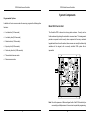
S105
Coded Access Controller
Including Systems;
CS109 - Combined door entry & coded entry
CK111 - Coded entry (216 keypad)
CK112 - Coded entry (217 Keypad)
PD-016 Issue 2
Bell System (Telephones) Ltd.
Presley Way, Crown Hill, Milton Keynes MK8 0ET.
Tel: 01908 261106 FAX: 01908 261116
email: [email protected] website: www.bellsystem.co.uk
S105 Coded Access Controller
Summary of Features
S105 Coded Access Controller
Contents
!
Up to 10 codes each of 1 - 8 Digits.
!
Time restricted access.
!
Duress Operation.
!
Exit Facility.
!
Lock Timer.
!
Secure Programming via Keypad.
!
Integrated PSU and Controller.
!
Battery Backup Capability.
!
Non-volatile Memory.
General Description . . . . . . . . . . . . . . . . . . . . . . . . . . . . . . . . . . . . . . . . . . . . . 5
Basic Operation . . . . . . . . . . . . . . . . . . . . . . . . . . . . . . . . . . . . . . . . . 5
Main Features: . . . . . . . . . . . . . . . . . . . . . . . . . . . . . . . . . . . . . . . . . . 6
System Components . . . . . . . . . . . . . . . . . . . . . . . . . . . . . . . . . . . . . . . . . . . 10
Model S105 Control Unit . . . . . . . . . . . . . . . . . . . . . . . . . . . . . . . . .
Power Supply . . . . . . . . . . . . . . . . . . . . . . . . . . . . . . . . . . . . . . . . . .
Electric Lock releases . . . . . . . . . . . . . . . . . . . . . . . . . . . . . . . . . . .
Model 216 & 217 Keypad . . . . . . . . . . . . . . . . . . . . . . . . . . . . . . . . .
10
11
11
12
Wiring for the S105 Controller . . . . . . . . . . . . . . . . . . . . . . . . . . . . . . . . . . . . 13
Products
S105
Installation Instructions . . . . . . . . . . . . . . . . . . . . . . . . . . . . . . . . . . . . . . . . . 14
Coded access controller
CK111 Complete kit incorporating S105 and 216 keypad
CK112 Complete kit incorporating S105 and 217 keypad
CS109 Combined coded access and door entry system
1
Cable requirements . . . . . . . . . . . . . . . . . . . . . . . . . . . . . . . . . . . . .
Fitting the Power Supply/Control Unit . . . . . . . . . . . . . . . . . . . . . . .
Important Safety Information . . . . . . . . . . . . . . . . . . . . . . . . . . . . . .
Cables . . . . . . . . . . . . . . . . . . . . . . . . . . . . . . . . . . . . . . . . . . . . . . . .
Battery . . . . . . . . . . . . . . . . . . . . . . . . . . . . . . . . . . . . . . . . . . . . . . .
Installing the keypads . . . . . . . . . . . . . . . . . . . . . . . . . . . . . . . . . . . .
Electric Lock Release . . . . . . . . . . . . . . . . . . . . . . . . . . . . . . . . . . . .
High current lock releases . . . . . . . . . . . . . . . . . . . . . . . . . . . . . . . .
High Current Lock Release . . . . . . . . . . . . . . . . . . . . . . . . . . . . . . .
Alarm Output . . . . . . . . . . . . . . . . . . . . . . . . . . . . . . . . . . . . . . . . . .
Time-clock . . . . . . . . . . . . . . . . . . . . . . . . . . . . . . . . . . . . . . . . . . . .
Exit Button . . . . . . . . . . . . . . . . . . . . . . . . . . . . . . . . . . . . . . . . . . . .
2
14
15
15
16
16
17
18
19
19
20
20
21
S105 Coded Access Controller
S105 Coded Access Controller
Programming the S105 . . . . . . . . . . . . . . . . . . . . . . . . . . . . . . . . . . . . . . . . . 22
Specification for the S105 Controller . . . . . . . . . . . . . . . . . . . . . . . . . . . . . . 49
General . . . . . . . . . . . . . . . . . . . . . . . . . . . . . . . . . . . . . . . . . . . . . . .
Programming a New Access Codes (Functions 1 to 10) . . . . . . . . .
Choosing an access code . . . . . . . . . . . . . . . . . . . . . . . . . . . . . . . . .
Programming the Action Codes (Functions 51 to 60) . . . . . . . . . . .
Changing the Security key (Function 91) . . . . . . . . . . . . . . . . . . . . .
Programming a Code Entry Time Limit (Function 94) . . . . . . . . . . .
Programming The Lock Duration (Function 95) . . . . . . . . . . . . . . . .
Programming a Lock Delay Time (Function 96) . . . . . . . . . . . . . . .
Programming The Alarm Duration (Function 97) . . . . . . . . . . . . . . .
Programming The Key Limit (Function 98) . . . . . . . . . . . . . . . . . . .
Programming the Factory Settings from the Keypad (Function 99)
...............................................
22
23
24
25
27
28
29
30
31
32
33
Summary of Program Functions . . . . . . . . . . . . . . . . . . . . . . . . . . . . . . . . . . 35
Table 1 - Programming Access Codes . . . . . . . . . . . . . . . . . . . . . . .
Table 2 - Programming of Other Functions . . . . . . . . . . . . . . . . . . .
Table 3 - Programming of Action Codes . . . . . . . . . . . . . . . . . . . . .
Table 4 - Summary of Action Numbers . . . . . . . . . . . . . . . . . . . . . .
35
36
37
38
Combined Door Entry and Coded Access Controller . . . . 51
General Description . . . . . . . . . . . . . . . . . . . . . . . . . . . . . . . . . . . . . . . . . . . . 52
CS109 Complete Systems . . . . . . . . . . . . . . . . . . . . . . . . . . . . . . . . 52
Installation of the Door Entryphone System . . . . . . . . . . . . . . . . . . 53
Cable Planning . . . . . . . . . . . . . . . . . . . . . . . . . . . . . . . . . . . . . . . . . . . . . . . 54
Cable requirements . . . . . . . . . . . . . . . . . . . . . . . . . . . . . . . . . . . . . 55
Installation Procedure . . . . . . . . . . . . . . . . . . . . . . . . . . . . . . . . . . . 56
Troubleshooting . . . . . . . . . . . . . . . . . . . . . . . . . . . . . . . . . . . . . . . . . . . . . . . 57
Testing and Troubleshooting . . . . . . . . . . . . . . . . . . . . . . . . . . . . . . . . . . . . . 39
Programming the Factory Settings Using the Test Button . . . . . . . . 41
CS109 - 1 Wiring . . . . . . . . . . . . . . . . . . . . . . . . . . . . . . . . . . . . . . . . . . . . . . 60
Testing The S105 . . . . . . . . . . . . . . . . . . . . . . . . . . . . . . . . . . . . . . . . . . . . . . 43
CS109 - N Wiring . . . . . . . . . . . . . . . . . . . . . . . . . . . . . . . . . . . . . . . . . . . . . 61
Testing The Lock Release Outputs . . . . . . . . . . . . . . . . . . . . . . . . .
Testing the Alarm Outputs . . . . . . . . . . . . . . . . . . . . . . . . . . . . . . . .
Testing the Keypad . . . . . . . . . . . . . . . . . . . . . . . . . . . . . . . . . . . . . .
Keypad Matrix . . . . . . . . . . . . . . . . . . . . . . . . . . . . . . . . . . . . . . . . . .
Testing the controller with factory settings . . . . . . . . . . . . . . . . . . . .
3
43
45
46
47
48
4
S105 Coded Access Controller
S105 Coded Access Controller
General Description
Main Features:
The S105 Coded Access Controller is a high quality, versatile security product,
controlling access to one door by means of a keypad and an electric lock release
Multi-coded
mechanism.
The S105 has ten access codes available each of which can be 1 to 8 digits long.
The extra codes are provided for a variety of possible uses:-
Basic Operation
C
Multi-user applications, e.g. for a small office block.
If a valid code is entered on the keypad, the lock release will operate for a preset
C
Time-restricted access (described below).
duration.
C
Duress access (described below).
The S105 Controller may be programmed with up to ten unique access codes.
The controller may be programmed to operate an audible alarm under various
circumstances, for example, if an invalid code has been repeatedly entered; the
Time-Restricted Access (Staff/Executive Operation)
alarm will operate for a preset period, during which time the lock release cannot
Any of the ten access codes may be programmed to operate during a restricted
operate.
time period, i.e. when an external time-clock switch is either open or closed.
The keypad has one green and one red LED to indicate the system status to the
user; the green LED indicates that the lock release is operating, whilst the red
For example, with factory settings, the operation of code 1 is unrestricted
LED indicates an invalid entry or an alarm condition.
(Executive Code) whilst code 2 is restricted to when the time-clock input is closed
(Staff Code).
Two codes could also be programmed to operate during alternate shifts. E.g.
code 1 operates when the time-clock input is open and code 2 operates when the
time-clock input is closed.
Refer to ‘Programming the Action Codes’ page 25 and Table 1 page 37 for
further details.
5
6
S105 Coded Access Controller
S105 Coded Access Controller
Duress Access
Non-Volatile Memory
Any of the ten access codes may be set to duress mode. When a duress code
The access codes and user programs are stored in a protected non-volatile
is entered, the lock release will operate normally but immediately afterwards
EEPROM memory, which does not rely on batteries. The access codes and
activate an alarm. The alarm device should be a discreet sounder or indicator
other programmable parameters are retained indefinitely without power.
designed to alert security staff.
Alternatively, the duress code can be programmed to directly operate the alarm,
without releasing the door.
Integrated Power Supply With Optional Battery Backup
The S105 controller is mounted in a rugged steel enclosure complete with an
Refer to ‘Programming the Action Codes’ page 25 and Table 1 page 37 for
integral power supply . This cost-effective approach, significantly reduces the
further details.
number of system components and the amount of cabling.
There is provision for an optional battery, which will maintain system operation
Exit Facility
in the event of a mains failure.
The Exit facility allows the lock release to be operated directly from a push-button
(for the preset time period). Typically this would be used to allow personnel to
freely exit through the controlled door. The facility may also be used for a
Fireman’s keyswitch, or to interface with other security products such as a Door
Entry Telephone System.
Lock Delay
If required, the lock release can be programmed to operate after a preset time
delay, following entry of the access code. This function is useful if the keypad
is located a long way from the entrance.
7
8
S105 Coded Access Controller
S105 Coded Access Controller
System Components
Programmable Options
In addition to the ten access codes the user may program the following other
functions:
Model S105 Control Unit
L Lock duration (1-99 seconds)
The Controller PCB is housed in a strong steel enclosure. Security can be
L Lock delay time (0-99 seconds)
further enhanced by placing the controller in a secured area. This arrangement
provides a superior level of security when compared to the many combined
L Alarm duration (1-99 seconds)
keypad/controller units on the market, where access can usually be attained by
L Key entry limit (0-99 seconds)
vandalism of the keypad; with a correctly installed S105 system this is
L Code entry time limit (0-99 seconds)
impossible.
L Time-restricted access mode
L Duress access mode.
Note Due to the presence of Mains voltages the lid of the S105 should only be
removed by qualified personnel. Access is not required for programming.
9
10
S105 Coded Access Controller
S105 Coded Access Controller
Model 216 & 217 Keypad
Power Supply
The Model 216 and 217 are 12-key Stainless-Steel Keypads, offering a high level
The S105 controller has its own internal Power Supply, rated at 12VDC and
of vandal and water resistance (i.e. suitable for indoor or outdoor use), and
0.8Amp. This power supply is sufficient to operate the Controller, a lock release
available with either an attractive alloy-cast surface-mounting enclosure or a
(max. 0.5A), a speech unit (see combined systems, page 50) and also to charge
flush-fitting (216 only) Zintec back-box. A red and a green LED indicator are
the battery; if fitted.
provided for status indication; Green indicates door open; Red indicates alarm
condition.
Electric Lock releases
The S105 Controller has outputs for both Fail-secure and Fail-safe Lock
Releases. These will drive a wide range of devices including magnetic locks.
11
12
S105 Coded Access Controller
S105 Coded Access Controller
Wiring for the S105 Controller
Installation Instructions
Read carefully all of the information presented in this chapter and then install the
system in accordance with the wiring diagram on page 13.
Cable requirements
Unless otherwise specified below, it is recommended that the system be installed
with solid-core telephone cable such as BT specification CW1308.
Connections
No. of
Cable length
cores
Core
diameter
Keypad
10
100M max.
0.5mm
Lock release (up to 500mA)
2
up to 25M
0.5mm
up to 100M
1.0mm
Alarm output (up to 50mA)
2
up to 100M
0.5mm
Time
2
100M max.
0.5mm
Exit
2
100M max.
0.5mm
In most cases cable length restrictions should not present a problem, however
where longer lengths are required please refer to the manufacturer for advice.
13
14
S105 Coded Access Controller
S105 Coded Access Controller
Fitting the Power Supply/Control Unit
Cables
The S105 controller is supplied in a steel box which should be installed in a
protected indoor environment. The box contains a number of mounting holes
Use only mains cable to BS6004, BS6500, or equivalent, within the following
and conduit holes, for safety reasons do not alter the box in any way.
specified limits:
When removing or replacing the lid take care not to damage or trap the earth
leads. For safety always ensure the earth leads are correctly connected.
Minimum
Maximum
Conductor Diameter
1.0mm (0.75mm2)
2.25mm (4mm2)
Cable Diameter
4.0mm
8.0mm
Important Safety Information
Battery
The S105 Unit and any other mains-powered equipment (e.g. Time-Clock) must
be placed in a protected indoor environment, close to a 240V electrical supply,
Care must be taken to ensure the battery terminals are not shorted together by
e.g. an electrical cupboard. Connections to the 240V AC mains supply must be
metal objects as this may constitute a Fire Hazard.
carried out by a qualified electrician or similar competent person, and made in
accordance with accepted safety practices.
Observe the correct polarity when connecting:
A good mains safety earth must be connected to the S105.
A two-pole switch (as provided by a Consumer Unit or Switch-Fuse) must be
Red wire
Positive
Black wire
Negative
included to isolate both Live and Neutral during Installation or Maintenance. The
¿
×
circuit must be protected by a current limiting fuse or other device with a
The Battery is protected by a fuse, always replace this with the correct type and
maximum rating of 5A.
rating:
The transformer is protected by a fuse; always replace this with the correct type
F1A 250V
and rating:
(20mm glass fuse, 1A, Fast Blow, approved to BS EN 60127 or
equivalent.)
T100mA 250V (20mm glass fuse, 100mA, 250V, Time delay, approved to
BS EN 60127 or equivalent.)
15
Battery type:
12V 2AH e.g. YUASA NP1.9-12
16
S105 Coded Access Controller
S105 Coded Access Controller
Electric Lock Release
Installing the keypads
The S105 Controller PCB provides two alternative pairs of connections for an
The keypad is supplied with an Allen key for removing the security screws in the
front panel and gaining access to the terminals. When fixing the keypad ensure
any drainage holes are at the base of the keypad and clear.
Each keypad requires 10 connections to the S105 controller as shown in the
wiring diagram, page 13. Do not run this cable alongside mains cables or other
transmission cables for any great distance. The keypad interface has a high
degree of noise immunity, which is adequate in most situations. With very long
cable runs, especially if operating in a noisy environment, it is advisable to use
a screened cable; connect the screen to DC negative (H -) at the Controller.
electric lock release: ‘FAIL SECR’ : Use these connections for ‘Fail-Secure’ lock releases. These
devices require power to release the lock and will secure the door in the event
of power failure. These are the most commonly used lock releases.
‘FAIL SAFE’ : Use these connections for ‘Fail-Safe’ lock releases and magnetic
locks. Both of these devices require continuous power to lock the door and will
release the door if power fails.
These outputs are rated at 12V DC with a maximum current consumption of
0.5A. For lock releases of higher current specification please refer to the next
section.
17
18
S105 Coded Access Controller
S105 Coded Access Controller
High current lock releases
Alarm Output
For a lock release or a magnetic lock rated higher than 0.5A or for AC operation
an additional power supply will be required. In addition a relay must be used to
The output is 12V DC at 50mA and may drive a variety of DC sounders,
interface with the S105.
indicators, or a relay for more powerful devices.
The relay contacts, or the lock-release, must be fitted with a suitable suppression
device to prevent electromagnetic interference being generated by the coil of the
Time-clock
lock release. (Refer to the manufacturer for further advice).
The terminal pair marked ‘TIME’ on the S105 PCB can be connected to an
Consideration should be given to the problem of a voltage drop at the lock
external switch to enable the second access code (factory setting). This switch
release. Refer to the manufacturer of the particular lock release for information
may be a simple keyswitch, operated manually, or more usually a Time-Clock.
on suitable cable length/thickness and power supply rating.
The switch contact must be fully isolated (i.e. voltage-free).
High Current Lock Release
19
20
S105 Coded Access Controller
S105 Coded Access Controller
Programming the S105
Exit Button
The terminal marked ‘EXIT’ may be connected to an external push-button for
egress operation. Momentarily operating this button will directly operate the lock
General
release for the programmed duration.
The 10 access codes, lock time etc, are all programmed via the keypad. To
Alternatively, the input may be used with a Fireman’s Override keyswitch, which
prevent unauthorised use, a security key (1 - 8 digits) must be entered.
should be of the normally-open type. If this feature is to be used it is important
The basic principle of programming is as follows:
that the lock release be of a continuously-rated design.
In general, a switch connected to the ‘EXIT’ terminals should be fully isolated i.e.
voltage-free.
Procedure
L Enter the security key (1 to 8 digit number).
L Enter a key sequence on the keypad.
L Observe both the red and green LEDs flash for one second.
L When all functions are programmed, exit program mode by
pressing **.
Each program function is described in detail on the following pages.
21
22
S105 Coded Access Controller
S105 Coded Access Controller
Choosing an access code
Programming a New Access Codes (Functions 1 to 10)
The S105 has ten access codes. Each code may be between 1 to 8 digits long.
To ensure an adequate level of security it is recommended that a minimum of 4
digits be used for each access code, giving 10,000 combinations. Codes should
be chosen carefully to avoid obvious sequences and repetitions (e.g. 12345, 258,
4444) which may be easily guessed or discovered. Try to choose codes with a
Procedure
random appearance (e.g. 6149, 186403) and avoid telephone numbers and other
meaningful codes which, again, may be guessed by a would-be intruder. It is
also a good idea to regularly change the access codes.
Examples
L Enter the security key.
1 * 7754#
When choosing access codes it is important that no code is a subset of another
(code 1 = 7754)
code, e.g. If code 1 = 234 and the code 2 = 12345, code 2 would never open the
L Red and green LEDs Flash
5 * 8652#
door as 234 is a subset of 12345.
L Exit program mode by pressing **
(code 5 = 8652)
L Type : <1 - 10> * <New Code> #
Maintenance
It is important also that the keypad be regularly cleaned to remove finger marks
which would otherwise give clues as to the keys used in the access code.
23
24
S105 Coded Access Controller
S105 Coded Access Controller
Code
Action
Programming the Action Codes (Functions 51 to 60)
Each access code has an associated action number. This is a single digit from
0
No action ( code is disabled)
1
Lock operates
2
Lock operates only if Time contacts are closed
3
Lock operates only if Time contacts are open
4
Lock operates followed by alarm (duress code)
0-9 which determines the action that occurs following the entry of that access
code.
Procedure
5
Example
L Enter the security key.
L Type : <51 - 60> * <Action No> #
51 * 1 #
6
Code 1:Act No=1
L Red and green LEDs Flash
(Operate lock
L Exit program mode by pressing **
always)
No
51
52
53 - 60
Function
Code 1 Action
Number
Code 2 Action
Number
Codes 3 to 10
Action Number
Key Sequence
Factory Setting
51 * <0-9> #
1 (Operate always)
52 * <0-9> #
2 (Operate when
Time closed)
53 - 60 * <0-9> #
0 (Disabled)
25
Lock, followed by alarm (duress code), if the Time contacts are
closed
Lock, followed by alarm (duress code), if the Time contacts are
open
7
Alarm operates
8
Alarm operates only if Time contacts are closed
9
Alarm operates only if Time contacts are open
26
S105 Coded Access Controller
S105 Coded Access Controller
Changing the Security key (Function 91)
Programming a Code Entry Time Limit (Function 94)
The security key is the code that must be entered on the keypad to gain access
to program mode.
This limits the time allowed for entry of the correct access code. Timing starts
To ensure an adequate level of security it is recommended that a minimum of 4
digits be used for the security key, giving 10,000 combinations.
from pressing the first key and if the remainder of the access code has not been
entered before this time limit elapses the alarm is activated. The code entry time
limit is programmable from 1-99 seconds or this feature is disabled by selecting
a time of ‘0'
Procedure
Procedure
L Enter the current security key.
Example
L Type : 91 * <New Key> #
91 * 87305 #
L Enter the security key.
L Red and green LEDs Flash
(security key =
L Type : 94 * <0-99> #
87305)
L Red and green LEDs Flash
L Exit program mode by pressing **
Factory Setting = 1212
Example
94 * 20 #
(limit of 20 secs)
L Exit program mode by pressing **
Factory Setting = 0 (disabled)
NOTE:
When the code entry time limit function is disabled the S105 will
automatically engage a timed memory clear function. If no key has
been pressed for 10 seconds all previous entries will be cleared; this
is important to ensure that the system cannot be left primed by a
partially entered but otherwise correct access code.
27
28
S105 Coded Access Controller
S105 Coded Access Controller
Programming The Lock Duration (Function 95)
Programming a Lock Delay Time (Function 96)
This is the duration the lock release will operate for when triggered by an access
This function causes a delay (0-99 seconds) to be introduced between the
code or by the ‘EXIT’ input. It is programmable in the range 1-99 seconds.
triggering of the lock release and its operation. Typically, this facility is used
when the keypad is located some distance from the entrance.
Procedure
Procedure
Example
L Enter the security key.
95 * 7 #
L Enter the security key.
(7 seconds)
L Type : 96 * <0-99> #
96 * 3 #
L Red and green LEDs Flash
95 * 12 #
L Red and green LEDs Flash
(3 second
L Exit program mode by pressing **
(12 seconds)
L Type : 95 * <1-99> #
Example
L Exit program mode by pressing **
Factory Setting = 0 seconds
Factory Setting = 3 seconds
29
delay)
30
S105 Coded Access Controller
S105 Coded Access Controller
Programming The Alarm Duration (Function 97)
Programming The Key Limit (Function 98)
The alarm output is triggered by either a duress code or by a repeated entry of
The key limit determines the number of keys that may be pressed in attempting
an incorrect code. The Alarm duration determines the time for which this output
to enter the correct access code before activating the Alarm. Choose a value
is active before automatically resetting. It is programmable in the range 1-99
which is a multiple of the number of digits in the code e.g for a 4 digit code set
seconds.
the key limit to 12 to allow 3 attempts. To disable this feature program the key
limit to 0.
Procedure
Procedure
L Enter the security key.
Example
L Type : 97 * <1-99> #
#97 * 60 #
L Red and green LEDs Flash
L Enter the security key.
Example
L Type : 98 * <0-99> #
98 * 12 #
(60 seconds)
L Exit program mode by pressing **
Factory Setting = 30 seconds
L Red and green LEDs Flash
(limit 12 keys)
L Exit program mode by pressing **
Factory Setting = 0 (disabled)
31
32
S105 Coded Access Controller
S105 Coded Access Controller
Programming the Factory Settings from the Keypad
Summary of Factory Settings
(Function 99)
In the event of any problems, always return to Factory settings.
Procedure
L Enter the security key.
If you have forgotten the
L Type : 99 * #
security key see
No
Function
Factory Setting
1
Program Code 1
12345
2
Program Code 2
67890
3 - 10
Program Codes 3 to 10
Disabled
51
Code 1 Action Number
1 (Operate always)
52
Code 2 Action Number
2 (Operate when Time
closed)
Code 3 to 10 Action Numbers
0 (Disabled)
91
Security key
1 2 12
94
Code Entry Time Limit
0 (Disabled)
95
Lock Duration
3 seconds
96
Lock Delay
0 (Disabled)
97
Alarm Duration
30 seconds
98
Key Limit
0 (Disabled)
‘Programming the
L Red and green LEDs Flash
Factory Defaults Using
L Exit program mode by
the Test Button’ page 41.
pressing **
33
53 - 60
34
S105 Coded Access Controller
S105 Coded Access Controller
Summary of Program Functions
Table 2 - Programming of Other Functions
Table 1 - Programming Access Codes
No.
Function
Key sequence
Factory Setting
No
Function
Key Sequence
Factory Setting
91
Security key
91 * <1-8 digits> #
1 2 12
94
Code Entry Time Limit
94 * <0-99 secs> #
0 (Disabled)
95
Lock Duration
95 * <1-99 secs> #
3 seconds
1
Program Code 1
1 * <1-8 digits> #
12345
2
Program Code 2
2 * <1-8 digits> #
67890
3
Program Code 3
3 * <1-8 digits> #
Disabled
96
Lock Delay
96 * <0-99 secs> #
0 (Disabled)
4
Program Code 4
4 * <1-8 digits> #
Disabled
97
Alarm Duration
97 * <0-99 secs> #
30 seconds
5
Program Code 5
5 * <1-8 digits> #
Disabled
98
Key Limit
98 * <0-99 keys> #
0 (Disabled)
6
Program Code 6
6 * <1-8 digits> #
Disabled
99
7
Program Code 7
7 * <1-8 digits> #
Disabled
8
Program Code 8
8 * <1-8 digits> #
Disabled
9
Program Code 9
9 * <1-8 digits> #
Disabled
10
Program Code 10
10 * <1-8 digits> #
Disabled
35
Program Factory
Settings
99 * #
36
S105 Coded Access Controller
S105 Coded Access Controller
Table 3 - Programming of Action Codes
Table 4 - Summary of Action Numbers
No
Function
Key Sequence
Factory Setting
51
Code 1 Action Number
51 * <0-9> #
1 (Operate always)
0
No action ( code is disabled)
52
Code 2 Action Number
52 * <0-9> #
2 (Operate when
Time closed)
1
Lock operates
53
Code 3 Action Number
53 * <0-9> #
0 (Disabled)
2
Lock operates only if Time contacts are closed
54
Code 4 Action Number
54 * <0-9> #
0 (Disabled)
3
Lock operates only if Time contacts are open
55
Code 5 Action Number
55 * <0-9> #
0 (Disabled)
4
Lock operates followed by alarm (duress code)
56
Code 6 Action Number
56 * <0-9> #
0 (Disabled)
5
57
Code 7 Action Number
57 * <0-9> #
0 (Disabled)
58
Code 8 Action Number
58 * <0-9> #
0 (Disabled)
6
59
Code 9 Action Number
59 * <0-9> #
0 (Disabled)
60
Code 10 Action Number
60 * <0-9> #
0 (Disabled)
37
Code
Action
Lock, followed by alarm (duress code), if the Time contacts are
closed
Lock, followed by alarm (duress code), if the Time contacts are
open
7
Alarm operates
8
Alarm operates only if Time contacts are closed
9
Alarm operates only if Time contacts are open
38
S105 Coded Access Controller
S105 Coded Access Controller
Testing and Troubleshooting
Symptom
Possible Cause/Remedy
Use the table below to determine the most probable cause of a fault condition
Lock operates when the
Ž
and perform any suggested tests which are described in detail in the following
test button is used but
Restore to Factory Settings (page 33,
pages.
does not operate when
41);
code is entered.
Symptom
Possible Cause/Remedy
Ž
Power Supply is overloaded; Remove
external connected components until the
When power applied
fault disappears (+, -, Locks, Alarm,
nothing happens (LEDs do
Keypad)
not flash)
Ž
Ž
Test keypad and connections (page 46)
Ž
‘EXIT’ terminals are short-circuited;
Ž
Temporarily remove connections to
Lock release is
permanently active
‘EXIT’ and re-test unit.
Ž
Lock release operates in
safe and Fail-secure outputs.
Check Fuses. Always replace with fuses
Ž
Alarm output does not
Ž
flash together when
lock-release output (page 43)
release
Ž
Ensure unit is correctly programmed
pages 33, 41)
operate
Ž
Test Alarm output (page 45)
Ž
Restore factory settings (page 41) and
circuited or of an incorrect rating; Check
attempting to operate lock-
Lock release does not
Fail-secure Lock release output is short-
Incorrect output has been used;
Transpose connections between Fail-
reverse
of the correct type and rating.
Red and Green LEDs
Check S105 is correctly programmed;
Security key doesn’t work
reprogram as required.
Test by applying a short-circuit directly to
operate when Exit Button
the ‘EXIT’ terminals; Check connections
is operated.
to Exit button.
39
40
S105 Coded Access Controller
S105 Coded Access Controller
Programming the Factory Settings Using the Test Button
In the event of any problems, always return to Factory settings. If the keypad is
not working, or the security key has been forgotten, the test button can be used
To program Factory Settings:
to restore factory settings.
L Press and hold the TEST button.
L Observe the red and green LEDs on (5 seconds).
Warning
Using the test button requires removing the lid of the
S105. To avoid the risk of electric shock care should
be taken not to touch anything other than the Test
Button. This operation should only be undertaken by
L Observe the red and green LEDs alternating (3 seconds).
L Finally the red and green LED will flash for 1 second and
extinguish. The Factory setting are now programmed; release the
TEST button.
qualified personnel.
This operation will restore all codes, times and functions to the factory settings
(see Table 1 page 35 for the complete list).
This facility is useful for fault diagnosis. It makes use of the Test Button on the
PCB rather than the keypad (which may have been incorrectly installed). It is
always advisable to return to this condition whenever the unit appears to
malfunction during installation or following an unsuccessful programming
session.
41
42
S105 Coded Access Controller
S105 Coded Access Controller
Testing The S105
The Controller PCB can be checked by measuring the voltage output on the lock
release pair; this should be the same as the power supply (13.8V). Note: the failsafe output will have voltage present except when the TEST button is pressed.
Testing The Lock Release Outputs
Ž
Ensure that the lock release is connected to the correct output (as shown in the
The power supply has been overloaded; look for either a short-circuit across the
wiring diagram on page 13). It is advisable to disconnect any connections to the
lock release output, or check that the lock release used requires less than
ALARM output temporarily for this test.
500mA @12V.
If pressing the TEST button causes the LEDs to flash immediately:
Warning Using the test button requires removing the lid of the S105.
To avoid the risk of electric shock care should be taken not
to touch anything other than the Test Button. This
operation should only be undertaken by qualified
personnel.
Ž
Press and hold the PCB TEST button:
Both of the Lock Outputs (Fail-Safe and Fail-Secure) and the Alarm Output will
operate; both red and green LEDs will illuminate.
Warning, after 5 seconds the LEDs will start to alternate and the lock and alarm
outputs will stop operating; you should release the test button at this stage to
avoid programming the factory settings.
Ž
If the LEDs turn on as described but the lock release fails to operate:
Check the lock release and its wiring by moving the lock connections to +C, -H.
43
44
S105 Coded Access Controller
S105 Coded Access Controller
Testing the Alarm Outputs
Testing the Keypad
Check that the alarm output is correctly wired to the device being used. It is
This test makes use of the red and green LED provided on the model 216/217
advisable to temporarily disconnect the lock release if it has not already been
keypads. If another keypad is being used which does not have LEDs it is
tested.
possible to use the LEDs on the PCB which duplicate their function; In this case,
Ž
Press and hold the PCB TEST button:
Both of the Lock Outputs (Fail-Safe and Fail-Secure) and the Alarm Output will
operate, and both red and green LEDs will illuminate.
After 5 seconds the LEDs will start to alternate and the lock and alarm outputs
it may be necessary to temporarily relocate the keypad closer to the controller
using a short length of cable. Obviously, if the system only exhibits a fault when
the keypad is returned to its position then the keypad cabling must be the cause.
L Program the unit to Factory Settings (see page 33, 41).
L Press the keys in the following sequence * 9 8 7 6 5 4 3 2 1 0
will stop operating; you should release the test button at this stage to avoid
L If the S105 controller reads these keys in the same sequence then the
green LED will flash briefly for each key-stroke.
programming the factory settings.
Ž
If the LEDs turn on as described but the alarm output fails to operate:
L If any keys appears out of sequence then the red LED will flash brief. This
Check the alarm device and its wiring by moving the connections to +C, -H. The
ends the test sequence (until the sequence is restarted with the * key).
Controller PCB can be checked by measuring the voltage output on the alarm
L To find more incorrect keys repeat the sequence, replacing the keys found
output pair; this should be the same as the power supply (13.8V).
Ž
If pressing the TEST button causes the LEDs to flash immediately:
The power supply has been overloaded; look for either a short-circuit across the
to be incorrect with the # key (This only works if the # key is correct!).
L A Faulty Row or Column of keys (or more) will tend to indicate a
connection fault (use the key matrix to identify faulty connection),
whereas a single faulty key would tend to suggest a faulty keypad.
Alarm output, or check that the alarm device used requires less than 50mA
@12V.
45
46
S105 Coded Access Controller
Keypad Matrix
S105 Coded Access Controller
Testing the controller with factory settings
Before proceeding with this test ensure that the lock release and alarm device
(if used) are working correctly by following the tests on pages 43 and 45
Program to factory settings by following the instructions on page 33, 41.
L Type in code 1 (1 2 3 4 5) - this should operate the lock release for 3
seconds.
L Remove connections to the ‘TIME’ terminals and type code 2 (6 7 8 9
0), nothing should happen. Now short-circuit the ‘TIME’ terminals
together with a short piece of wire and retype code 2 (6 7 8 9 0) - the
lock release should operate for 3 seconds.
L Reprogram code 1 to another value by following the instructions under the
heading ‘Programming new access codes’ (page 27); check that the new
code operates the lock release and that the old one does not.
If any of the above tests should fail then follow the keypad test procedure.
47
48
S105 Coded Access Controller
S105 Coded Access Controller
Specification for the S105 Controller
Power (C + & H -)
Output Voltage:
13.8V
Load (maximum):
200mA
Lock
Output Voltage:
13.8V
Load (maximum):
0.5A each output (load inductive or resistive)
Alarm
Output Voltage:
13.8V
Load (maximum):
50mA
Dimensions
S105 PCB:
154mm x 135mm
Steel Enclosure:
215mm x 200mm x 70mm
Standards
c
This Product complies with European Directive 89/336/EEC on
ElectroMagnetic Compatibility and Low Voltage Directive
73/23/EEC.
Made in the United Kingdom
49
50
Combined Door Entry and Coded Access
General Description
The CS109 series systems are combined Door Entry Telephone and Coded
Access Systems. The entrance panel incorporates a push button for each
telephone, a speaker grill and an integral keypad, similar in style to the Model
CS109 Series
Combined Door Entry and Coded Access
Controller
216 keypad.
CS109 Complete Systems
The CS109-N systems include all of the components necessary for a single-door
Coded Access and Door Entry Telephone System:1
S105 Coded Access Controller.
1
CP109-N Anodised Aluminium Entrance Panel with integral keypad and
Bell System (Telephones) Ltd.
surface mounting back-box.
1
61 or 51 Speech unit.
N
Model 500D Door Entry Telephones
1
Model 203 Lock Release.
N - specifies the number of push-buttons/telephones (eg CS109-3: 3 phone
system)
51
52
Combined Door Entry and Coded Access
Installation of the Door Entryphone System
Combined Door Entry and Coded Access
Cable Planning
From an electrical point of view, the combined systems may be regarded as
separate door entry and coded access systems with the exception of a common
lock release. The coded access system and its installation is described in detail
in the preceding half of this manual. The wiring diagram on page 60 shows the
wiring connections for the Door Entry Telephone System, including the simple
connections which interface with the S105 Coded Access Controller.
The Model 500D Door Entry Telephone
This is designed to be wall mounted in a convenient indoor location.
The Entrance Panel
The entrance panel, containing the speech unit, is supplied with either a surface
or flush-mounting back box. It should be mounted on a wall near the front door,
and in a sheltered location.
Extension Phones
Each apartment can have up to 3 extension phones (4 phones in total).
Tradesman button (optional)
This is used in conjunction with a time-clock to allow tradesmen access during
restricted hours. The time-clock may be 240V AC or 12V DC operated, but must
have a voltage-free isolated contact.
53
54
Combined Door Entry and Coded Access
Combined Door Entry and Coded Access
Cable requirements
Installation Procedure
For optimum clarity of speech it is strongly recommended that this system is
Connect all items by following the wiring diagram, on page 60. It is strongly
installed using twisted-pair telephone cable (e.g. type CW1308). Use one of the
recommended that a single telephone be connected at a time and fully tested
pairs for the R & O connection between the speech unit and the telephone.
before proceeding to the next.
Connections
No. of cores
Core
Cable length
Speech adjustment
diameter
Phone
4 + 1 per phone
0.5mm
100M max.
The model 51 and 61 speech units have two pots at the rear for adjustment of
Speech Unit and
13
0.5mm
100M max.
speech levels as follows:
Keypad
Lock release (up to
2
0.5mm
500mA)
Speech level at the Entrance Panel
Volume B:
Speech level at the Telephone
up to 25M
1.0mm
up to 100M
2
0.5mm
up to 100M
Time clock
2
0.5mm
100M max.
Exit
2
0.5mm
100M max.
Trades Button
2
0.5mm
100M max.
Alarm output (up to
Volume A:
50mA)
In most cases cable length restrictions should not present a problem, however
where longer lengths are required please refer to the manufacturer for advice.
55
56
Combined Door Entry and Coded Access
Combined Door Entry and Coded Access
Troubleshooting
Symptom
Possible Cause/Remedy
Ž
Use the table below to determine the most probable cause of a fault condition.
Speech Unit.
Refer also to page 39 for problems with the coded access system (S105).
Ž
Speech Unit is not tight against the panel
grill.
Telephone Problems
Ž
Symptom
Volume adjustment required on the
Possible Cause/Remedy
Constant tone/feedback
‘O’ connection between Speech unit and
telephone is open circuit.
when in use.
Ž
Volume adjustment required on speech
Ž
unit.
Ž
close together.
Speech unit is not tight against the panel
Ž
grill.
Low Speech Volume
Entrance panel and telephone are too
The entrance panel is surrounded by
reflecting walls.
Ž
Panel grill is blocked
Ž
More than one telephone is off the hook.
Ž
Speech unit supply voltage is low. Check
No speech when the
phone is buzzed
10V - 15V across ‘C’ and ‘H’.
Ž
Panel grill is blocked.
Ž
Wiring fault on the speech signal
connections ‘R’ or ‘T’: ‘R’ carries the phone
microphone signal to the speech unit; ‘T’
carries the Speech unit microphone to the
phone.
57
58
Combined Door Entry and Coded Access
Combined Door Entry and Coded Access
CS109 - 1 Wiring
Miscellaneous Problems
Symptom
Possible Cause/Remedy
Ž
Telephone will not buzz.
Faulty'O' or 'I' line between power supply
and phone. Check 10.5V - 15V across ‘I’
and ‘O’ when called.
Ž
Missing connection to S105 Exit terminal.
Ž
Fault on 'Z' or 'O' line.
Ž
Faulty ‘DOOR’ button on telephone.
Ž
Time-Clock is not running or incorrectly
Telephone ‘DOOR’ button
does not operate release;
S105 test button does
operate the lock
set (Trades button only).
Trades, Exit button or Fire
Switch inoperative.
Ž
Faulty 'Z' or 'O' wires between S105 and
button / switch. Check lock operates from
phone.
59
60
Combined Door Entry and Coded Access
CS109 - N Wiring
61