1
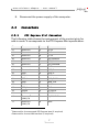
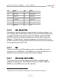
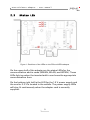
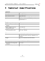
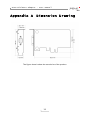
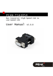
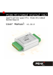
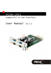
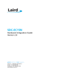
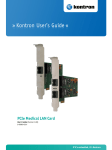
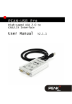
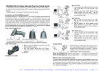
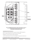
PCIe-miniPCIe Adapter (Low Profile)
PCI Express Adapter for miniPCIe Cards
User Manual
Document version 1.1.0 (2015-08-19)
PCIe-miniPCIe Adapter – User Manual
Products taken into account
Product Name
Model
Part Number
PCIe-miniPCIe Adapter
IPEH-003029
CANopen® and CiA® are registered community trade marks of CAN in Automation
e.V.
All other product names mentioned in this document may be the trademarks or
registered trademarks of their respective companies. They are not explicitly marked
by “™” and “®”.
Copyright © 2015 PEAK-System Technik GmbH
Duplication (copying, printing, or other forms) and the electronic distribution of this
document is only allowed with explicit permission of PEAK-System Technik GmbH.
PEAK-System Technik GmbH reserves the right to change technical data without
prior announcement. The general business conditions and the regulations of the
license agreement apply. All rights are reserved.
PEAK-System Technik GmbH
Otto-Roehm-Strasse 69
64293 Darmstadt
Germany
Phone: +49 (0)6151 8173-20
Fax:
+49 (0)6151 8173-29
www.peak-system.com
[email protected]
Document version 1.1.0 (2015-08-19)
2
PCIe-miniPCIe Adapter – User Manual
Contents
1
1.1
1.2
1.3
2
Introduction
4
Properties at a Glance
System Requirements
Scope of Supply
Hardware
6
2.1 Operation
2.2 Connectors
2.2.1
PCI Express Mini Connector
2.2.2
CAN Connection
2.2.3
USB
2.2.4
Micro-SIM Card Holder
2.3 Status LED
3
Technical Specifications
Appendix A
4
5
5
Dimension Drawing
3
6
7
7
8
8
8
9
10
11
PCIe-miniPCIe Adapter – User Manual
1
Introduction
With the help of the PCIe-miniPCIe adapter, you can operate PCI
Express Mini and Half PCI Express Mini cards in a computer with
low profile housing. Two spacers on the plug-in card can be
appropriately positioned to attach the card in place. The adapter
includes a Mini-USB socket, a Micro-SIM card holder, as well as a
voltage supply of 1.5 V and 3.3 V for plugged PCI Express Mini
cards.
In addition to the PCAN-miniPCIe from PEAK-System, USB solutions
as well as cards for wireless communications such as WLAN,
WWAN, and WPAN can be operated via the adapter.
1.1
Properties at a Glance
Form factor Low Profile
4-layer board with gold-plated connectors
PC plug-in card (PCIe x1) for the PCI Express slot
Suitable for operation of USB solutions and add-in cards for
wireless communication:
• WWAN (Wireless Wide Area Network, e. g. UMTS & GSM)
• WLAN (Wireless Local Area Network)
• WPAN (Wireless Personal Area Network, e. g. Bluetooth)
Status LEDs for power supply and state of communication
add-in cards
Mini-USB socket for operation of USB solutions
Micro-SIM card holder for operation of UMTS and GSM cards
4
PCIe-miniPCIe Adapter – User Manual
Supply voltage of the adapter of 3.3 V
Supply voltage of 1.5 V and 3.3 V for plugged PCI Express Mini
cards
Screw fixing for PCI Express Mini and Half PCI Express Mini
cards
Extended operating temperature range from -40 to +85 °C
(-40 to + 185°F)
1.2
System Requirements
A vacant PCI Express slot (PCIe-x1) in the computer
1.3
Scope of Supply
PCIe-miniPCIe adapter with mounted D-Sub slot bracket incl.
connection cable
Manual in PDF format
5
PCIe-miniPCIe Adapter – User Manual
2
Hardware
2.1
Operation
To attach a PCI Express Mini or a Half PCI Express Mini card on
the PCIe-miniPCIe adapter, proceed as follows:
1.
Unscrew the nuts on the spacer.
2.
Insert the PCI Express Mini card into the contact strip. Hold
the PCI Express Mini card in a slightly slanted position; slide
the card into the contact strip and fold it down.
3.
Refasten and tighten the PCI Express' spacer nuts.
Do the following to install the PCIe-miniPCIe adapter into the
computer:
Attention! Electrostatic discharge (ESD) can damage or destroy
components on the PCIe-miniPCIe adapter. Take precautions to
avoid ESD when handling the card.
1.
Shut down the computer and switch it off.
2.
Disconnect the computer from the power supply.
3.
Open the computer’s casing.
4.
If applicable, remove the front blind in front of the desired
slot of the PCIe-miniPCIe adapter.
5.
Connect the supplied special cable with the add-in card (e.g.
PCAN-miniPCIe).
6.
Insert the adapter into an empty PCI Express slot. Observe
the computer’s documentation for this.
7.
Close the computer’s casing.
6
PCIe-miniPCIe Adapter – User Manual
8.
2.2
2.2.1
Reconnect the power supply of the computer.
Connectors
PCI Express Mini Connector
The following table shows the assignment of the contact strip for
add-in cards. It corresponds to the PCI Express Mini specification.
Pin
1
2
Name
Pin
Name
51
Reserved
1
52
+3.3 V
49
Reserved1
50
GND
47
Reserved1
48
+1.5 V
45
Reserved1
46
LED_WPAN#
43
Reserved1
44
LED_WLAN#
41
Reserved1
42
LED_WWAN#
39
Reserved1
40
GND
37
Reserved
1
38
USB_D+
35
GND
36
USB_D-
33
PETp0
34
GND
31
PETn0
32
SMB_DATA
29
GND
30
SMB_CLK
27
GND
28
+1.5 V
25
PERp0
26
GND
23
PERn0
24
+3.3 Vaux
21
GND
22
PERST#
19
Reserved 2
(UIM_C4)
20
W_DISABLE#
17
Reserved2
(UIM_C8)
18
GND
Reserved for future second PCI Express lane (if required)
Reserved for future UIM interface (if required)
7
PCIe-miniPCIe Adapter – User Manual
Pin
Name
15
GND
16
UIM_VVP
13
REFCLK+
14
UIM_RESET
11
REFCLK-
12
UIM_CLK
9
GND
10
UIM_DATA
7
CLKREQ#
8
UIM_PWR
5
Reserved 3
6
1.5 V
3
Reserved3
4
GND
1
WAKE#
2
3.3 V
2.2.2
Pin
Name
CAN Connection
The adapter has the technical requirements for the operation of a
PCI Express Mini CAN adapter. When using a PCAN-miniPCIe card,
connect the D-Sub connector of the slot bracket with the PCANminiPCIe card by using the supplied connection cable (see also
Chapter 2.1 Operating). The pin assignment is determined by the
PCAN-miniPCIe card (see PCAN-miniPCIe manual) and corresponds
to the specification CiA® 102.
2.2.3
USB
Connect the PCIe-miniPCIe adapter with a free USB port on the
computer via a USB cable. The USB port is used exclusively as a
data line, and can not be used for the power supply.
2.2.4
Micro-SIM Card Holder
This card holder is suitable for a micro-SIM card. Should the
adapter be operated in the WWAN mode (e.g. UMTS, GSM, or
GPRS) a micro-SIM card must be inserted.
3
Reserved for future wireless coexistence control interface (if required)
8
PCIe-miniPCIe Adapter – User Manual
2.3
Status LED
Figure 1: Positions of the LEDs on the PCIe-miniPCIe adapter
On the upper half of the adapter are the status LEDs for the
communication add-in cards (WWAN, WLAN, and WPAN). These
LEDs light up when the inserted add-in card uses the appropriate
communication form.
On the bottom right half is the LED for the 1.5 V power supply and
the one for 3.3 V is located in the middle. The power supply LEDs
will stay lit continuously when the adapter card is correctly
supplied.
9
PCIe-miniPCIe Adapter – User Manual
3
Technical Specifications
Connectors
CAN
D-Sub (m), 9 pins
Mini-USB socket
Mini-USB 2.0, 5 pin
Micro-SIM card holder
Micro-SIM card
Computer
PCI Express x1 (1 Lane), Specification 1.1
Slot
PCI Express Mini and Half PCI Express Mini,
Specification 1.1
Supply
Supply voltage of the adapter
3.3 V
Current consumption of the
adapter
max. 20 mA
Supply voltage for the PCI
Express Mini cards
1.5 V and 3.3 V
Current consumption for the
PCI Express Mini cards
1.5 V max. 375 mA
3.3 V max. 1100 mA
Measures
Size
69 x 100 x 1.5 mm (W x L x H)
See also dimension drawing in Appendix A on
page 11
Weight
45 g, incl. mounted D-Sub slot bracket
Environment
Operating temperature
-40 - +85 °C (-40 - +185 °F)
Temperature for storage and
transport
-40 - 125°C
Relative humidity
15 - 90 %, not condensing
10
PCIe-miniPCIe Adapter – User Manual
Appendix A
Dimension Drawing
The figure doesn’t show the actual size of the product.
11