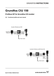
1
PTQ-AFC Modicon Quantum Platform Liquid and Gas Flow Computer for Hydrocarbon Products March 4, 2011 USER MANUAL Your Feedback Please We always want you to feel that you made the right decision to use our products. If you have suggestions, comments, compliments or complaints about our products, documentation, or support, please write or call us. How to Contact Us ProSoft Technology 5201 Truxtun Ave., 3rd Floor Bakersfield, CA 93309 +1 (661) 716-5100 +1 (661) 716-5101 (Fax) www.prosoft-technology.com [email protected] Copyright © 2011 ProSoft Technology, Inc., all rights reserved. PTQ-AFC User Manual March 4, 2011 ProSoft Technology ®, ProLinx ®, inRAx ®, ProTalk ®, and RadioLinx ® are Registered Trademarks of ProSoft Technology, Inc. All other brand or product names are or may be trademarks of, and are used to identify products and services of, their respective owners. ProSoft Technology® Product Documentation In an effort to conserve paper, ProSoft Technology no longer includes printed manuals with our product shipments. User Manuals, Datasheets, Sample Ladder Files, and Configuration Files are provided on the enclosed CD-ROM, and are available at no charge from our web site: www.prosoft-technology.com Information for ProTalk® Product Users The statement "power, input and output (I/O) wiring must be in accordance with Class I, Division 2 wiring methods Article 501-10(b) of the National Electrical Code, NFPA 70 for installations in the U.S., or as specified in section 181J2 of the Canadian Electrical Code for installations within Canada and in accordance with the authority having jurisdiction". The following or equivalent warnings shall be included: A Warning - Explosion Hazard - Substitution of components may Impair Suitability for Class I, Division 2; B Warning - Explosion Hazard - When in Hazardous Locations, Turn off Power before replacing Wiring Modules, and C Warning - Explosion Hazard - Do not Disconnect Equipment unless Power has been switched Off or the Area is known to be Nonhazardous. D Caution: The Cell used in this Device may Present a Fire or Chemical Burn Hazard if Mistreated. Do not Disassemble, Heat above 100°C (212°F) or Incinerate. WARNING - EXPLOSION HAZARD - DO NOT DISCONNECT EQUIPMENT UNLESS POWER HAS BEEN SWITCHED OFF OR THE AREA IS KNOWN TO BE NON-HAZARDOUS. AVERTISSEMENT - RISQUE D'EXPLOSION - AVANT DE DÉCONNECTER L'ÉQUIPEMENT, COUPER LE COURANT OU S'ASSURER QUE L'EMPLACEMENT EST DÉSIGNÉ NON DANGEREUX. Warnings North America Warnings A B C Warning - Explosion Hazard - Substitution of components may impair suitability for Class I, Division 2. Warning - Explosion Hazard - When in hazardous locations, turn off power before replacing or rewiring modules. Warning - Explosion Hazard - Do not disconnect equipment unless power has been switched off or the area is known to be non-hazardous. Suitable for use in Class I, Division 2 Groups A, B, C and D Hazardous Locations or Non-Hazardous Locations. ATEX Warnings and Conditions of Safe Usage: Power, Input, and Output (I/O) wiring must be in accordance with the authority having jurisdiction. A Warning - Explosion Hazard - When in hazardous locations, turn off power before replacing or wiring modules. B Warning - Explosion Hazard - Do not disconnect equipment unless power has been switched off or the area is known to be non-hazardous. C These products are intended to be mounted in an IP54 enclosure. The devices shall provide external means to prevent the rated voltage being exceeded by transient disturbances of more than 40%. This device must be used only with ATEX certified backplanes. D DO NOT OPEN WHEN ENERGIZED. Electrical Ratings Backplane Current Load: 1100 mA maximum @ 5 Vdc ± 5% Operating Temperature: 0°C to 60°C (32°F to 140°F) Storage Temperature: -40°C to 85°C (-40°F to 185°F) Shock: 30 g operational; 50 g non-operational; Vibration: 5 g from 10 to 150 Hz Relative Humidity: 5% to 95% (without condensation) All phase conductor sizes must be at least 1.3 mm(squared) and all earth ground conductors must be at least 4mm(squared). Markings: CE CSA/cUL CSA CB Certified ATEX 243333 EMC-EN61326-1:2006; EN6100-6-4:2007 C22.2 No. 213-1987 IEC61010 EN60079-0 Category 3, Zone 2 EN60079-15 ME06 Important Notice: CAUTION: THE CELL USED IN THIS DEVICE MAY PRESENT A FIRE OR CHEMICAL BURN HAZARD IF MISTREATED. DO NOT DISASSEMBLE, HEAT ABOVE 100°C (212°F) OR INCINERATE. Maximum battery load = 200 μA. Maximum battery charge voltage = 3.4 Vdc. Maximum battery charge current = 500 μA. Maximum battery discharge current = 30 μA. PTQ-AFC ♦ Modicon Quantum Platform Liquid and Gas Flow Computer for Hydrocarbon Products Contents User Manual Contents Your Feedback Please........................................................................................................................ 2 How to Contact Us .............................................................................................................................. 2 ProSoft Technology® Product Documentation .................................................................................... 2 Information for ProTalk® Product Users .............................................................................................. 3 Warnings ............................................................................................................................................. 3 Important Notice: ................................................................................................................................. 4 Guide to the PTQ-AFC User Manual 11 1 13 Start Here 1.1 1.2 1.3 1.3.1 2 Configuring the Processor with Unity Pro 2.1 2.2 2.3 2.4 2.4.1 2.5 3 Introduction .............................................................................................................. 14 Update Notice .......................................................................................................... 15 Hardware and Software Requirements ................................................................... 17 Package Contents ................................................................................................... 17 Creating a New Project ........................................................................................... 20 Adding the PTQ Module to the Project.................................................................... 22 Building the Project ................................................................................................. 24 Connect Your PC to the Processor ......................................................................... 25 Connecting to the Processor with TCPIP ................................................................ 27 Downloading the Project to the Quantum Processor .............................................. 28 Configuring the Processor with Concept 3.1 3.1.1 3.2 3.3 3.4 3.5 3.6 19 29 Information for Concept Version 2.6 Users ............................................................. 30 Installing MDC Configuration Files .......................................................................... 30 Creating a New Project ........................................................................................... 32 Adding the PTQ Module to the Project.................................................................... 35 Setting up Data Memory in Project ......................................................................... 38 Downloading the Project to the Processor .............................................................. 41 Verifying Successful Download ............................................................................... 43 4 Configuring the Processor with ProWORX 47 5 Setting Up the ProTalk Module 51 5.1 5.1.1 5.1.2 5.1.3 5.2 5.2.1 ProSoft Technology, Inc. June 23, 2011 Installing the ProTalk Module in the Quantum Rack ............................................... 52 Verifying Jumper Settings ....................................................................................... 52 Inserting the 1454-9F connector ............................................................................. 52 Installing the ProTalk Module in the Quantum Rack ............................................... 53 Connect the PC to the ProTalk Configuration/Debug Port...................................... 54 Troubleshooting AFC Manager Connection Problems ........................................... 55 Page 5 of 259 Contents User Manual 6 PTQ-AFC ♦ Modicon Quantum Platform Liquid and Gas Flow Computer for Hydrocarbon Products Quick Start 6.1 6.1.1 6.2 6.3 6.3.1 6.3.2 6.3.3 6.3.4 6.3.5 6.3.6 6.3.7 6.4 6.5 6.6 6.7 6.7.1 6.7.2 6.7.3 6.7.4 6.7.5 6.7.6 6.8 6.8.1 6.8.2 6.8.3 6.9 6.9.1 6.9.2 6.9.3 6.9.4 6.10 6.10.1 6.10.2 6.10.3 6.10.4 6.11 6.11.1 6.11.2 6.11.3 6.11.4 6.11.5 6.11.6 6.11.7 6.11.8 6.11.9 6.11.10 6.12 6.12.1 6.12.2 6.12.3 6.12.4 6.12.5 Page 6 of 259 57 Install AFC Manager ............................................................................................... 58 System Requirements ............................................................................................ 58 Starting AFC Manager ............................................................................................ 59 Using AFC Manager ............................................................................................... 60 Starting a New Project ............................................................................................ 60 Loading an Existing project..................................................................................... 61 Printing the Configuration Report ........................................................................... 61 Converting a Project ............................................................................................... 62 Resetting Configuration Parameters ...................................................................... 63 Downloading the Project to the Module .................................................................. 63 Verifying Correct Operation .................................................................................... 64 Ladder Logic Implementation ................................................................................. 66 Setting the Wallclock .............................................................................................. 68 Module Initialization ................................................................................................ 69 Meter Channel Functionality ................................................................................... 70 Meter Channels....................................................................................................... 70 Linear (Pulse) Meter Overview ............................................................................... 71 Differential (Orifice) Meter Overview....................................................................... 71 Gas Product Overview ............................................................................................ 73 Liquid Product Overview ......................................................................................... 74 General Features .................................................................................................... 75 Modbus Database ................................................................................................... 78 AFC Modbus Address Space ................................................................................. 78 Primary Slave.......................................................................................................... 79 Virtual Slave ............................................................................................................ 82 Modbus Communication ......................................................................................... 85 Communication Parameters ................................................................................... 85 Port Options ............................................................................................................ 86 Modbus Master ....................................................................................................... 87 Modbus Pass-Through ........................................................................................... 89 Accumulators .......................................................................................................... 90 Accumulator Totalizer and Residue ........................................................................ 90 Accumulator Types ................................................................................................. 91 Net Accumulator Calculation .................................................................................. 95 Frequently Asked Questions................................................................................... 95 Archives .................................................................................................................. 96 Archive Overview .................................................................................................... 96 Archive Generation ................................................................................................. 96 Archive Types ......................................................................................................... 98 Archive Order .......................................................................................................... 99 Archive Options..................................................................................................... 100 Archive Locations ................................................................................................. 101 Editing the Archive Structure ................................................................................ 102 Extended Archives ................................................................................................ 103 Archive Reports .................................................................................................... 106 Archive Monitor ..................................................................................................... 108 Events ................................................................................................................... 114 The Event Log....................................................................................................... 114 Event Log structures ............................................................................................. 115 Event Id Tag.......................................................................................................... 116 Event-triggered archives and accumulator resets ................................................ 117 Period-end events ................................................................................................. 117 ProSoft Technology, Inc. June 23, 2011 PTQ-AFC ♦ Modicon Quantum Platform Liquid and Gas Flow Computer for Hydrocarbon Products 6.12.6 6.12.7 6.12.8 6.12.9 6.12.10 6.12.11 6.12.12 6.13 6.13.1 7 8 ProSoft Technology, Inc. June 23, 2011 137 Prover Configuration ............................................................................................. 138 Prover Type ........................................................................................................... 138 Prover Options ...................................................................................................... 143 Run Counts ........................................................................................................... 144 Run Input Setup .................................................................................................... 144 Prover Characteristics ........................................................................................... 145 Setting up the AFC module for Meter Proving ...................................................... 148 Initial Requirements............................................................................................... 150 Meter Proving Alarms ............................................................................................ 152 Prover Operation (How to do a Prove) .................................................................. 155 Meter Proving Reports .......................................................................................... 162 Protected Meter Proving Data in the AFC's Input Register Bank ......................... 164 Latest Prove Results ............................................................................................. 164 Meter Previous Prove Summary ........................................................................... 166 Backplane Communication 9.1 9.1.1 9.1.2 9.1.3 9.1.4 9.1.5 9.1.6 9.2 9.2.1 9.2.2 9.2.3 9.3 9.3.1 9.3.2 133 Cable Connections ................................................................................................ 133 RS-232 Configuration/Debug Port ........................................................................ 133 RS-232 Application Port(s) ................................................................................... 133 RS-485 Application Port(s) .................................................................................... 135 RS-422 .................................................................................................................. 136 Meter Proving 8.1 8.1.1 8.1.2 8.1.3 8.1.4 8.1.5 8.2 8.2.1 8.2.2 8.2.3 8.3 8.4 8.4.1 8.4.2 9 Loggable events .................................................................................................... 118 Special events ....................................................................................................... 118 Site Datum Point events ........................................................................................ 119 Meter Datum Point events ..................................................................................... 121 Stream Datum Point events .................................................................................. 124 "Rkv" notes ............................................................................................................ 125 Event numbers and Event Log Download ............................................................. 126 Security (Passwords) ............................................................................................ 129 Hard Password ...................................................................................................... 130 Module Configuration 7.1 7.1.1 7.1.2 7.1.3 7.1.4 Contents User Manual 167 Site PLC Configuration .......................................................................................... 168 Supervisory Output Block ...................................................................................... 170 Supervisory Input Block......................................................................................... 172 Wallclock Block ..................................................................................................... 174 Modbus Gateway Block......................................................................................... 174 Modbus Pass-Thru Block ...................................................................................... 175 Modbus Master Block ............................................................................................ 176 Meter PLC Configuration ....................................................................................... 177 Process Input from PLC to AFC ............................................................................ 179 Calculations to PLC from AFC .............................................................................. 182 Archive Fetch to PLC from AFC ............................................................................ 183 Sample Files .......................................................................................................... 184 Concept Sample Files ........................................................................................... 184 Unity Sample Files ................................................................................................ 195 Page 7 of 259 Contents User Manual 10 PTQ-AFC ♦ Modicon Quantum Platform Liquid and Gas Flow Computer for Hydrocarbon Products Diagnostics and Troubleshooting 10.1 10.1.1 10.1.2 10.2 10.3 10.4 10.5 10.6 11 Reference 201 User LEDs............................................................................................................. 202 App Stat LED ........................................................................................................ 202 Cfg, Prt2 or Prt3 .................................................................................................... 202 BBRAM LEDs ....................................................................................................... 203 Meter Alarms......................................................................................................... 204 Checksum Alarms ................................................................................................. 207 Events ................................................................................................................... 208 Audit Scan............................................................................................................. 209 214 11.1 General Specifications .......................................................................................... 215 11.1.1 On-line Communication & Configuration .............................................................. 216 11.1.2 Reports ................................................................................................................. 216 11.1.3 Modbus Interface .................................................................................................. 216 11.1.4 Configurable Options ............................................................................................ 217 11.1.5 Supported Meters ................................................................................................. 217 11.1.6 Hardware Specifications ....................................................................................... 218 11.2 Measurement Standards ...................................................................................... 219 11.2.1 Basic Metering According to Meter type ............................................................... 219 11.2.2 Liquid Correction Factor Details ........................................................................... 222 11.3 Sealable Parameters ............................................................................................ 224 11.4 Wedge Meter Applications .................................................................................... 225 11.5 Configurable Archive Registers ............................................................................ 226 11.5.1 Information for Users of AFC Manager Versions Older Than 2.01.000 ............... 229 11.6 Archive Data Format ............................................................................................. 231 11.6.1 Timestamp Date and Time Format ....................................................................... 231 11.6.2 Pre-defined Header .............................................................................................. 231 11.6.3 Orifice (Differential) Meter with Gas Product ........................................................ 232 11.6.4 Pulse (Linear) Meter with Gas Product ................................................................. 233 11.6.5 Orifice (Differential) Meter with Liquid Product ..................................................... 233 11.6.6 Pulse (Linear) Meter with Liquid Product .............................................................. 234 11.6.7 Flow Rate Integration with Gas Product ............................................................... 235 11.6.8 Pulse Frequency Integration with Gas Product .................................................... 235 11.6.9 Flow Rate Integration with Liquid Product ............................................................ 235 11.6.10 Pulse Frequency Integration with Liquid Product ................................................. 236 11.7 Modbus Addressing Common to Both Primary and Virtual Slaves ...................... 237 11.8 Modbus Port configuration .................................................................................... 240 11.9 Startup Basics and Frequently Asked Questions ................................................. 242 11.9.1 How does the module work? ................................................................................ 242 11.9.2 Why should I use the AFC Manager? ................................................................... 242 11.9.3 Why can't the AFC Manager connect to the module? .......................................... 243 11.9.4 Why do I have to enable or disable a meter? ....................................................... 243 11.9.5 Why does the card not calculate results, or why did it stop calculating results? .. 243 11.9.6 What is the Virtual Modbus Slave? ....................................................................... 243 11.9.7 How does the AFC Manager transfer the configuration to the module? .............. 244 11.9.8 What is the password used for? ........................................................................... 244 11.9.9 Why do I receive an Illegal Data Value warning when I try to write a meter configuration or download the entire configuration to the module? .......................................... 244 11.9.10 Why is the Molar Analysis button disabled? ......................................................... 244 11.9.11 Why does the AFC Manager show a "Communication Timeout" warning? ......... 245 Page 8 of 259 ProSoft Technology, Inc. June 23, 2011 PTQ-AFC ♦ Modicon Quantum Platform Liquid and Gas Flow Computer for Hydrocarbon Products 11.9.12 11.9.13 11.9.14 11.9.15 11.9.16 11.9.17 11.9.18 11.9.19 12 Contents User Manual What is the difference between Net Accumulator and Gross Accumulator? ........ 245 What are the accumulator’s totalizer and residue values? ................................... 245 Do I have to enter all molar concentrations for the gas product? ......................... 245 Can I update the molar concentration values dynamically?.................................. 245 Why do the accumulator values not update? ........................................................ 245 What is the Wallclock? .......................................................................................... 246 Can I read the Primary (or Virtual) Slave values using the AFC Manager? ......... 246 When are the archives generated? ....................................................................... 246 Support, Service & Warranty 248 Contacting Technical Support ......................................................................................................... 248 12.1 Return Material Authorization (RMA) Policies and Conditions.............................. 250 12.1.1 Returning Any Product .......................................................................................... 250 12.1.2 Returning Units Under Warranty ........................................................................... 251 12.1.3 Returning Units Out of Warranty ........................................................................... 251 12.2 LIMITED WARRANTY........................................................................................... 252 12.2.1 What Is Covered By This Warranty ....................................................................... 252 12.2.2 What Is Not Covered By This Warranty ................................................................ 253 12.2.3 Disclaimer Regarding High Risk Activities ............................................................ 253 12.2.4 Intellectual Property Indemnity .............................................................................. 254 12.2.5 Disclaimer of all Other Warranties ........................................................................ 254 12.2.6 Limitation of Remedies ** ...................................................................................... 255 12.2.7 Time Limit for Bringing Suit ................................................................................... 255 12.2.8 No Other Warranties ............................................................................................. 255 12.2.9 Allocation of Risks ................................................................................................. 255 12.2.10 Controlling Law and Severability ........................................................................... 255 Index ProSoft Technology, Inc. June 23, 2011 256 Page 9 of 259 Contents User Manual Page 10 of 259 PTQ-AFC ♦ Modicon Quantum Platform Liquid and Gas Flow Computer for Hydrocarbon Products ProSoft Technology, Inc. June 23, 2011 PTQ-AFC ♦ Modicon Quantum Platform Liquid and Gas Flow Computer for Hydrocarbon Products Guide to the PTQ-AFC User Manual User Manual Guide to the PTQ-AFC User Manual Section to Read Function Details Introduction (Must Do) Start Here (page 13) This section introduces the customer to the module. Included are: package contents, system requirements, hardware installation, and basic configuration. Diagnostic and Troubleshooting Diagnostics and Troubleshooting (page 201) This section describes Diagnostic and Troubleshooting procedures. Reference Reference (page 214) These sections contain general references associated with this product, Specifications, and the Functional Overview. Product Specifications Product Specifications (page 215) Functional Overview Functional Overview Support, Service, and Warranty Support, Service and Warranty (page 248) Index This section contains Support, Service and Warranty information. Index of chapters. Index ProSoft Technology, Inc. June 23, 2011 Page 11 of 259 Guide to the PTQ-AFC User Manual User Manual Page 12 of 259 PTQ-AFC ♦ Modicon Quantum Platform Liquid and Gas Flow Computer for Hydrocarbon Products ProSoft Technology, Inc. June 23, 2011 PTQ-AFC ♦ Modicon Quantum Platform Liquid and Gas Flow Computer for Hydrocarbon Products 1 Start Here User Manual Start Here In This Chapter Introduction............................................................................................ 14 Update Notice........................................................................................ 15 Hardware and Software Requirements ................................................. 17 This guide is intended to guide you through the ProTalk module setup process, from removing the module from the box to exchanging data with the processor. In doing this, you will learn how to: Set up the processor environment for the PTQ module View how the PTQ module exchanges data with the processor Edit and download configuration files from your PC to the PTQ module Monitor the operation of the PTQ module ProSoft Technology, Inc. June 23, 2011 Page 13 of 259 Start Here User Manual 1.1 PTQ-AFC ♦ Modicon Quantum Platform Liquid and Gas Flow Computer for Hydrocarbon Products Introduction The PTQ-AFC Gas & Oil Flow Computer module performs measurement of Hydrocarbon Gases and Liquids using currently accepted industry measurement standards. The module consists of a single-slot solution for Quantum chassis. To obtain its process inputs for calculations, the module uses the process data collected by analog and pulse I/O modules. The processor transfers this data to the AFC module, which then calculates flow rates, accumulated volumes, and accumulated mass. The results of the calculations are transferred back to the processor for use in the application ladder logic, or for transfer to a SCADA host. The module has two communication ports for Modbus communication allowing easy access to a remote Modbus device. The module works as a Modbus slave or master device. As discussed later in this manual, the internal Modbus database can be accessed by a Modbus Master device and by the processor (using the Modbus Gateway Function). The AFC Manager software can be used for easy meter configuration and application monitoring. The following section provides a sample application where input data is transferred from the transmitters to analog input cards on the Schneider Electric rack and the values are transferred from the processor to the module. For Pulse meter applications, the pulse count and pulse frequency values are typically transmitted through high-speed counter modules in the rack. The module performs the flow calculation based on the values transferred through the backplane. The calculation results can be read to the processor or polled from a remote Modbus master unit connected to one of the communication ports. Page 14 of 259 ProSoft Technology, Inc. June 23, 2011 PTQ-AFC ♦ Modicon Quantum Platform Liquid and Gas Flow Computer for Hydrocarbon Products 1.2 Start Here User Manual Update Notice If your module measures liquids, please read this notice before upgrading from version 2.04 (or earlier) to 2.05 (or later). For compliance with new measurement standards, the AFC version 2.05 has introduced several new liquid product groups. In particular, the two non-refined liquid product groups of version 2.04, which covered the entire density range of crudes and NGLs, have each been split into two separate product groups, one for the higher density range of crudes and the other for the lower density range of NGLs. If your module has meter channels configured for either "Crude, NGL" or "Oil-water emulsion", you should decide before upgrading the firmware the new product group (light or heavy) to which each such channel should be assigned. This assignment will be performed during the upgrade process and will preserve all other configuration and historical records including accumulator values and archives, in contrast to changing a product group after the upgrade which resets the meter configuration and erases all historical records. Meter channels configured for "Gas" or "Refined products" are not affected. AFC Manager exhibits the same behavior when converting a project between versions 2.04 (or earlier) and 2.05 (or later). The criterion for assigning the new product group depends on the density units and the Default Reference Density, as described in the following tables: Density Units = kg/m3 Version 2.04 Product Group Crude, NGL Crude, NGL Oil Water Emulsion Oil Water Emulsion Default Reference Density = 0 OR 610.0 > 0 AND < 610.0 = 0 OR 610.0 > 0 AND 610.0 Version 2.05 Product Group Crude oils, JP4 NGLs, LPGs Oil-water emulsion (Crd) Oil-water emulsion (NGL) Density Units = Rd/60 Version 2.04 Product Group Crude, NGL Crude, NGL Oil Water Emulsion Oil Water Emulsion Default Reference Density = 0 OR 0.6100 > 0 AND < 0.6100 = 0 OR 0.6100 > 0 AND < 0.6100 Version 2.05 Product Group Crude oils, JP4 NGLs, LPGs Oil-water emulsion (Crd) Oil-water emulsion (NGL) Due to roundoff error of numeric conversions, a Relative Density very close to the cutoff value of 0.6100 may cause the module to assign the new product group opposite to the one that was intended. Before upgrading, change the Default Reference Density to a number significantly different from 0.6100, such as 0.6110 (to target Crude) or 0.6090 (to target NGLs). You may change it back to the correct value after the upgrade. ProSoft Technology, Inc. June 23, 2011 Page 15 of 259 Start Here User Manual PTQ-AFC ♦ Modicon Quantum Platform Liquid and Gas Flow Computer for Hydrocarbon Products Density Units = API Gravity Version 2.04 Product Group Crude, NGL Crude, NGL Oil Water Emulsion Oil Water Emulsion Page 16 of 259 Default Reference Density = 0 OR 100.0 > 0 AND > 100.0 = 0 OR 100.0 > 0 AND > 100.0 Version 2.05 Product Group Crude oils, JP4 NGLs, LPGs Oil-water emulsion (Crd) Oil-water emulsion (NGL) ProSoft Technology, Inc. June 23, 2011 PTQ-AFC ♦ Modicon Quantum Platform Liquid and Gas Flow Computer for Hydrocarbon Products 1.3 Start Here User Manual Hardware and Software Requirements 1.3.1 Package Contents ProTalk Module Null Modem Serial Cable 1454-9F DB-9 Female to 9 Pos Screw Terminal adapter (Serial protocol modules only) ProSoft Solutions CD Note: The DB-9 Female to 5 Pos Screw Terminal adapter is not required on Ethernet modules and is therefore not included in the carton with these types of modules. ProSoft Technology, Inc. June 23, 2011 Page 17 of 259 Start Here User Manual PTQ-AFC ♦ Modicon Quantum Platform Liquid and Gas Flow Computer for Hydrocarbon Products Quantum Hardware This guide assumes that you are familiar with the installation and setup of the Quantum hardware. The following should be installed, configured, and powered up before proceeding: Quantum Processor Quantum rack Quantum power supply Quantum Modbus Plus Network Option Module (NOM Module) (optional) Quantum to PC programming hardware NOM Ethernet or Serial connection to PC PC and PC Software ProSoft Technology recommends the following minimum hardware to use the module: Windows PC with 80486 based processor (Pentium preferred) with at least one COM, USB, or Ethernet port 1 megabyte of system memory Unity™ Pro PLC Programming Software, version 3.0 or later or Concept™ PLC Programming Software, version 2.6 or later or Other Quantum Programming Software Note: ProTalk module configuration files are compatible with common Quantum programming applications, including Unity Pro and Concept. For all other programming applications, please contact technical support. Page 18 of 259 ProSoft Technology, Inc. June 23, 2011 PTQ-AFC ♦ Modicon Quantum Platform Liquid and Gas Flow Computer for Hydrocarbon Products 2 Configuring the Processor with Unity Pro User Manual Configuring the Processor with Unity Pro In This Chapter Creating a New Project.......................................................................... 20 Adding the PTQ Module to the Project .................................................. 22 Building the Project ............................................................................... 24 Connect Your PC to the Processor ....................................................... 25 Downloading the Project to the Quantum Processor ............................. 28 The following steps are designed to ensure that the processor (Quantum or Unity) is able to transfer data successfully with the PTQ module. As part of this procedure, you will use Unity Pro to create a project, add the PTQ module to the project, set up data memory for the project, and then download the project to the processor. ProSoft Technology, Inc. June 23, 2011 Page 19 of 259 Configuring the Processor with Unity Pro User Manual 2.1 PTQ-AFC ♦ Modicon Quantum Platform Liquid and Gas Flow Computer for Hydrocarbon Products Creating a New Project The first step is to open Unity Pro and create a new project. 1 In the New Project dialog box, choose the CPU type. In the following illustration, the CPU is 140 CPU 651 60. Choose the processor type that matches your own hardware configuration, if it differs from the example. Click OK to continue. 2 Next, add a power supply to the project. In the Project Browser, expand the Configuration folder, and then double-click the 1:LOCALBUS icon. This action opens a graphical window showing the arrangement of devices in your Quantum rack. Page 20 of 259 ProSoft Technology, Inc. June 23, 2011 PTQ-AFC ♦ Modicon Quantum Platform Liquid and Gas Flow Computer for Hydrocarbon Products Configuring the Processor with Unity Pro User Manual 3 Select the rack position for the power supply, and then click the right mouse button to open a shortcut menu. On the shortcut menu, choose NEW DEVICE. 4 Expand the Supply folder, and then select your power supply from the list. Click OK to continue. 5 Repeat these steps to add any additional devices to your Quantum Rack. ProSoft Technology, Inc. June 23, 2011 Page 21 of 259 Configuring the Processor with Unity Pro User Manual 2.2 PTQ-AFC ♦ Modicon Quantum Platform Liquid and Gas Flow Computer for Hydrocarbon Products Adding the PTQ Module to the Project 1 Expand the Communication tree, and select GEN NOM. This module type provides extended communication capabilities for the Quantum system, and allows communication between the PLC and the PTQ module without requiring additional programming. Page 22 of 259 ProSoft Technology, Inc. June 23, 2011 PTQ-AFC ♦ Modicon Quantum Platform Liquid and Gas Flow Computer for Hydrocarbon Products Configuring the Processor with Unity Pro User Manual 2 Next, enter the module personality value. The correct value for ProTalk modules is 1060 decimal (0424 hex). 3 Before you can save the project in Unity Pro, you must validate the modifications. Open the EDIT menu, and then choose VALIDATE. If no errors are reported, you can save the project. SAVE the project. 4 ProSoft Technology, Inc. June 23, 2011 Page 23 of 259 Configuring the Processor with Unity Pro User Manual 2.3 PTQ-AFC ♦ Modicon Quantum Platform Liquid and Gas Flow Computer for Hydrocarbon Products Building the Project Whenever you update the configuration of your PTQ module or the processor, you must import the changed configuration from the module, and then build (compile) the project before downloading it to the processor. Note: The following steps show you how to build the project in Unity Pro. This is not intended to provide detailed information on using Unity Pro, or debugging your programs. Refer to the documentation for your processor and for Unity Pro for specialized information. To build (compile) the project: 1 2 3 Review the elements of the project in the Project Browser. When you are satisfied that you are ready to download the project, open the BUILD menu, and then choose REBUILD ALL PROJECT. This action builds (compiles) the project into a form that the processor can use to execute the instructions in the project file. This task may take several minutes, depending on the complexity of the project and the resources available on your PC. As the project is built, Unity Pro reports its process in a Progress dialog box, with details appearing in a pane at the bottom of the window. The following illustration shows the build process under way. After the build process is completed successfully, the next step is to download the compiled project to the processor. Page 24 of 259 ProSoft Technology, Inc. June 23, 2011 PTQ-AFC ♦ Modicon Quantum Platform Liquid and Gas Flow Computer for Hydrocarbon Products 2.4 Configuring the Processor with Unity Pro User Manual Connect Your PC to the Processor The next step is to connect to the processor so that you can download the project file. The processor uses this project file to communicate over the backplane to modules identified in the project file. Note: If you have never connected from the PC to your processor before, you must verify that the necessary port drivers are installed and available to Unity Pro. To verify address and driver settings in Unity Pro 1 Open the PLC menu, and choose STANDARD MODE. This action turns off the PLC Simulator, and allows you to communicate directly with the Quantum or Unity hardware. 2 Open the PLC menu, and choose SET ADDRESS... This action opens the Set Address dialog box. Open the MEDIA dropdown list and choose the connection type to use (TCPIP or USB). ProSoft Technology, Inc. June 23, 2011 Page 25 of 259 Configuring the Processor with Unity Pro User Manual PTQ-AFC ♦ Modicon Quantum Platform Liquid and Gas Flow Computer for Hydrocarbon Products 3 If the MEDIA dropdown list does not contain the connection method you wish to use, click the COMMUNICATION PARAMETERS button in the PLC area of the dialog box. This action opens the PLC Communication Parameters dialog box. 4 Click the DRIVER SETTINGS button to open the SCHNEIDER Drivers management Properties dialog box. 5 Click the INSTALL/UPDATE button to specify the location of the Setup.exe file containing the drivers to use. You will need your Unity Pro installation disks for this step. 6 Click the BROWSE button to locate the Setup.exe file to execute, and then execute the setup program. After the installation, restart your PC if you are prompted to do so. Refer to your Schneider Electric documentation for more information on installing drivers for Unity Pro. Page 26 of 259 ProSoft Technology, Inc. June 23, 2011 PTQ-AFC ♦ Modicon Quantum Platform Liquid and Gas Flow Computer for Hydrocarbon Products Configuring the Processor with Unity Pro User Manual 2.4.1 Connecting to the Processor with TCPIP The next step is to download (copy) the project file to the processor. The following steps demonstrate how to use an Ethernet cable connected from the Processor to your PC through an Ethernet hub or switch. Other connection methods may also be available, depending on the hardware configuration of your processor, and the communication drivers installed in Unity Pro. 1 If you have not already done so, connect your PC and the processor to an Ethernet hub. 2 Open the PLC menu, and then choose SET ADDRESS. Important: Notice that the Set Address dialog box is divided into two areas. Enter the address and media type in the PLC area of the dialog box, not the Simulator area. 3 Enter the IP address in the address field. In the MEDIA dropdown list, choose TCPIP. Click the TEST CONNECTION button to verify that your settings are correct. 4 ProSoft Technology, Inc. June 23, 2011 Page 27 of 259 Configuring the Processor with Unity Pro User Manual 2.5 PTQ-AFC ♦ Modicon Quantum Platform Liquid and Gas Flow Computer for Hydrocarbon Products Downloading the Project to the Quantum Processor 1 2 Open the PLC menu and then choose CONNECT. This action opens a connection between the Unity Pro software and the processor, using the address and media type settings you configured in the previous step. On the PLC menu, choose TRANSFER PROJECT TO PLC. This action opens the TRANSFER PROJECT TO PLC dialog box. If you would like the PLC to go to "Run" mode immediately after the transfer is complete, select (check) the PLC RUN AFTER TRANSFER check box. Click the TRANSFER button to download the project to the processor. As the project is transferred, Unity Pro reports its process in a PROGRESS dialog box, with details appearing in a pane at the bottom of the window. When the transfer is complete, place the processor in Run mode. The processor will start scanning your process logic application. 3 Page 28 of 259 ProSoft Technology, Inc. June 23, 2011 PTQ-AFC ♦ Modicon Quantum Platform Liquid and Gas Flow Computer for Hydrocarbon Products 3 Configuring the Processor with Concept User Manual Configuring the Processor with Concept In This Chapter Information for Concept Version 2.6 Users............................................ 30 Creating a New Project.......................................................................... 32 Adding the PTQ Module to the Project .................................................. 35 Setting up Data Memory in Project ........................................................ 38 Downloading the Project to the Processor............................................. 41 Verifying Successful Download ............................................................. 43 The following steps are designed to ensure that the processor is able to transfer data successfully with the PTQ module. As part of this procedure, you will use Concept configuration software from Schneider Electric to create a project, add the PTQ module to the project, set up data memory for the project, and then download the project to the processor. Important Note: Concept software does not report whether the PTQ module is present in the rack, and therefore is not able to report the health status of the module when the module is online with the Quantum processor. Please consider this when monitoring the status of the PTQ module. ProSoft Technology, Inc. June 23, 2011 Page 29 of 259 Configuring the Processor with Concept User Manual 3.1 PTQ-AFC ♦ Modicon Quantum Platform Liquid and Gas Flow Computer for Hydrocarbon Products Information for Concept Version 2.6 Users This guide uses Concept PLC Programming Software version 2.6 to configure the Quantum PLC. The ProTalk installation CD includes MDC module configuration files that help document the PTQ installation. Although not required, these files should be installed before proceeding to the next section. 3.1.1 Installing MDC Configuration Files 1 From a PC with Concept 2.6 installed, choose START / PROGRAMS / CONCEPT / MODCONNECT TOOL. This action opens the Concept Module Installation dialog box. 2 Choose FILE / OPEN INSTALLATION FILE. This action opens the Open Installation File dialog box: If you are using a Quantum processor, you will need the MDC files. In the Open Installation File dialog box, navigate to the MDC Files directory on the ProTalk CD. 4 Choose the MDC file and help file for your version of Concept: o Concept 2.6 users: select PTQ_2_60.mdc and PTQMDC.hlp o Concept 2.5 users: select PTQ_2_50.mdc and PTQMDC.hlp. 3 Page 30 of 259 ProSoft Technology, Inc. June 23, 2011 PTQ-AFC ♦ Modicon Quantum Platform Liquid and Gas Flow Computer for Hydrocarbon Products Configuring the Processor with Concept User Manual Select the files that go with the Concept version you are using, and then click OK. This action opens the Add New Modules dialog box. 5 6 Click the ADD ALL button. A series of message boxes may appear during this process. Click YES or OK for each message that appears. When the process is complete, open the FILE menu and choose EXIT to save your changes. ProSoft Technology, Inc. June 23, 2011 Page 31 of 259 Configuring the Processor with Concept User Manual 3.2 PTQ-AFC ♦ Modicon Quantum Platform Liquid and Gas Flow Computer for Hydrocarbon Products Creating a New Project This phase of the setup procedure must be performed on a computer that has the Concept configuration software installed. 1 From your computer, choose START / PROGRAMS / CONCEPT V2.6 XL.EN / CONCEPT. This action opens the Concept window. 2 Open the File menu, and then choose NEW PROJECT. This action opens the PLC Configuration dialog box. Page 32 of 259 ProSoft Technology, Inc. June 23, 2011 PTQ-AFC ♦ Modicon Quantum Platform Liquid and Gas Flow Computer for Hydrocarbon Products Configuring the Processor with Concept User Manual 3 In the list of options on the left side of this dialog box, double-click the PLC SELECTION folder. This action opens the PLC Selection dialog box. 4 In the CPU/Executive pane, use the scroll bar to locate and select the PLC to configure. ProSoft Technology, Inc. June 23, 2011 Page 33 of 259 Configuring the Processor with Concept User Manual PTQ-AFC ♦ Modicon Quantum Platform Liquid and Gas Flow Computer for Hydrocarbon Products 5 Click OK. This action opens the PLC Configuration dialog box, populated with the correct values for the PLC you selected. 6 Make a note of the holding registers for the module. You will need this information when you modify your application. The Holding Registers are displayed in the PLC Memory Partition pane of the PLC Configuration dialog box. Page 34 of 259 ProSoft Technology, Inc. June 23, 2011 PTQ-AFC ♦ Modicon Quantum Platform Liquid and Gas Flow Computer for Hydrocarbon Products 3.3 Configuring the Processor with Concept User Manual Adding the PTQ Module to the Project 1 In the list of options on the left side of the PLC Configuration dialog box, double-click I/O MAP. This action opens the I/O Map dialog box. 2 Click the EDIT button to open the Local Quantum Drop dialog box. This dialog box is where you identify rack and slot locations. ProSoft Technology, Inc. June 23, 2011 Page 35 of 259 Configuring the Processor with Concept User Manual PTQ-AFC ♦ Modicon Quantum Platform Liquid and Gas Flow Computer for Hydrocarbon Products 3 Click the MODULE button next to the rack/slot position where the ProTalk module will be installed. This action opens the I/O Module Selection dialog box. 4 In the Modules pane, use the scroll bar to locate and select the ProTalk module, and then click OK. This action copies the description of the ProTalk module next to the assigned rack and slot number of the Local Quantum Drop dialog box. Page 36 of 259 ProSoft Technology, Inc. June 23, 2011 PTQ-AFC ♦ Modicon Quantum Platform Liquid and Gas Flow Computer for Hydrocarbon Products 5 Configuring the Processor with Concept User Manual Repeat steps 3 through 5 for each ProTalk module you plan to install. When you have finished installing your ProTalk modules, click OK to save your settings. Click YES to confirm your settings. Tip: Select a module, and then click the Help on Module button for help pages. ProSoft Technology, Inc. June 23, 2011 Page 37 of 259 Configuring the Processor with Concept User Manual 3.4 PTQ-AFC ♦ Modicon Quantum Platform Liquid and Gas Flow Computer for Hydrocarbon Products Setting up Data Memory in Project 1 In the list of options on the left side of the PLC Configuration dialog box, double-click SPECIALS. 2 This action opens the Specials dialog box. Page 38 of 259 ProSoft Technology, Inc. June 23, 2011 PTQ-AFC ♦ Modicon Quantum Platform Liquid and Gas Flow Computer for Hydrocarbon Products Configuring the Processor with Concept User Manual Selecting the Time of Day 1 Select (check) the Time of Day box, and then enter the value 00001 as shown in the following illustration. This value sets the first time of day register to 400001. 2 Click OK to save your settings and close the Specials dialog box. Saving your project 1 In the PLC Configuration dialog box, choose FILE / SAVE PROJECT AS. ProSoft Technology, Inc. June 23, 2011 Page 39 of 259 Configuring the Processor with Concept User Manual PTQ-AFC ♦ Modicon Quantum Platform Liquid and Gas Flow Computer for Hydrocarbon Products 2 This action opens the Save Project As dialog box. 3 Name the project, and then click OK to save the project to a file. Page 40 of 259 ProSoft Technology, Inc. June 23, 2011 PTQ-AFC ♦ Modicon Quantum Platform Liquid and Gas Flow Computer for Hydrocarbon Products 3.5 Configuring the Processor with Concept User Manual Downloading the Project to the Processor Next, download (copy) the project file to the Quantum Processor. 1 Use the null modem cable to connect your PC’s serial port to the Quantum processor, as shown in the following illustration. Note: You can use a Modbus Plus Network Option Module (NOM Module) module in place of the serial port if necessary. 2 3 Open the PLC menu, and then choose CONNECT. In the PLC Configuration dialog box, open the ONLINE menu, and then choose CONNECT. This action opens the Connect to PLC dialog box. 4 Leave the default settings as shown and click OK. Note: Click OK to dismiss any message boxes that appear during the connection process. ProSoft Technology, Inc. June 23, 2011 Page 41 of 259 Configuring the Processor with Concept User Manual PTQ-AFC ♦ Modicon Quantum Platform Liquid and Gas Flow Computer for Hydrocarbon Products 5 In the PLC Configuration window, open the ONLINE menu, and then choose DOWNLOAD. This action opens the Download Controller dialog box. 6 Click ALL, and then click DOWNLOAD. If a message box appears indicating that the controller is running, click YES to shut down the controller. The Download Controller dialog box displays the status of the download as shown in the following illustration. 7 When the download is complete, you will be prompted to restart the controller. Click YES to restart the controller. Page 42 of 259 ProSoft Technology, Inc. June 23, 2011 PTQ-AFC ♦ Modicon Quantum Platform Liquid and Gas Flow Computer for Hydrocarbon Products 3.6 Configuring the Processor with Concept User Manual Verifying Successful Download The final step is to verify that the configuration changes you made were received successfully by the module, and to make some adjustments to your settings. 1 In the PLC Configuration window, open the ONLINE menu, and then choose ONLINE CONTROL PANEL. This action opens the Online Control Panel dialog box. 2 Click the SET CLOCK button to open the Set Controller’s Time of Day Clock dialog box. 3 Click the WRITE PANEL button. This action updates the date and time fields in this dialog box. Click OK to close this dialog box and return to the previous window. Click CLOSE to close the Online Control Panel dialog box. In the PLC Configuration window, open the ONLINE menu, and then choose REFERENCE DATA EDITOR. This action opens the Reference Data Editor dialog box. On this dialog box, you will add preset values to data registers that will later be monitored in the ProTalk module. 4 5 ProSoft Technology, Inc. June 23, 2011 Page 43 of 259 Configuring the Processor with Concept User Manual PTQ-AFC ♦ Modicon Quantum Platform Liquid and Gas Flow Computer for Hydrocarbon Products 6 Place the cursor over the first address field, as shown in the following illustration. 7 In the PLC Configuration window, open the TEMPLATES menu, and then choose INSERT ADDRESSES. This action opens the Insert addresses dialog box. On the Insert Addresses dialog box, enter the values shown in the following illustration, and then click OK. 8 Page 44 of 259 ProSoft Technology, Inc. June 23, 2011 PTQ-AFC ♦ Modicon Quantum Platform Liquid and Gas Flow Computer for Hydrocarbon Products 9 Configuring the Processor with Concept User Manual Notice that the template populates the address range, as shown in the following illustration. Place your cursor as shown in the first blank address field below the addresses you just entered. 10 Repeat steps 6 through 9, using the values in the following illustration: 11 In the PLC Configuration window, open the ONLINE menu, and then choose ANIMATE. This action opens the RDE Template dialog box, with animated values in the Value field. 12 Verify that values shown are cycling, starting from address 400065 and up. ProSoft Technology, Inc. June 23, 2011 Page 45 of 259 Configuring the Processor with Concept User Manual PTQ-AFC ♦ Modicon Quantum Platform Liquid and Gas Flow Computer for Hydrocarbon Products 13 In the PLC Configuration window, open the TEMPLATES menu, and then choose SAVE TEMPLATE AS. Name the template ptqclock, and then click OK to save the template. 14 In the PLC Configuration window, open the ONLINE menu, and then choose DISCONNECT. At the disconnect message, click YES to confirm your choice. At this point, you have successfully Created and downloaded a Quantum project to the PLC Preset values in data registers that will later be monitored in the ProTalk module. You are now ready to complete the installation and setup of the ProTalk module. Page 46 of 259 ProSoft Technology, Inc. June 23, 2011 PTQ-AFC ♦ Modicon Quantum Platform Liquid and Gas Flow Computer for Hydrocarbon Products 4 Configuring the Processor with ProWORX User Manual Configuring the Processor with ProWORX When you use ProWORX 32 software to configure the processor, use the example SAF file provided on the ProTalk Solutions CD-ROM. Important Note: ProWORX software does not report whether the PTQ module is present in the rack, and therefore is not able to report the health status of the module when the module is online with the Quantum processor. Please consider this when monitoring the status of the PTQ module. 1 Run the SCHNEIDER_ALLIANCES.EXE application that is installed with the ProWORX 32 software: 2 Click on IMPORT… ProSoft Technology, Inc. June 23, 2011 Page 47 of 259 Configuring the Processor with ProWORX User Manual PTQ-AFC ♦ Modicon Quantum Platform Liquid and Gas Flow Computer for Hydrocarbon Products 3 Select the .SAF File that is located on the CD-ROM shipped with the PTQ module. 4 After you click on OPEN you should see the PTQ modules imported (select I/O SERIES as QUANTUM): Page 48 of 259 ProSoft Technology, Inc. June 23, 2011 PTQ-AFC ♦ Modicon Quantum Platform Liquid and Gas Flow Computer for Hydrocarbon Products Configuring the Processor with ProWORX User Manual Now you can close the Schneider alliances application and run the ProWORX 32 software. At the Traffic Cop section, select the PTQ module to be inserted at the slot: ProSoft Technology, Inc. June 23, 2011 Page 49 of 259 Configuring the Processor with ProWORX User Manual Page 50 of 259 PTQ-AFC ♦ Modicon Quantum Platform Liquid and Gas Flow Computer for Hydrocarbon Products ProSoft Technology, Inc. June 23, 2011 PTQ-AFC ♦ Modicon Quantum Platform Liquid and Gas Flow Computer for Hydrocarbon Products 5 Setting Up the ProTalk Module User Manual Setting Up the ProTalk Module In This Chapter Installing the ProTalk Module in the Quantum Rack .............................. 52 Connect the PC to the ProTalk Configuration/Debug Port .................... 54 After you complete the following procedures, the ProTalk module will actively be transferring data bi-directionally with the processor. ProSoft Technology, Inc. June 23, 2011 Page 51 of 259 Setting Up the ProTalk Module User Manual 5.1 PTQ-AFC ♦ Modicon Quantum Platform Liquid and Gas Flow Computer for Hydrocarbon Products Installing the ProTalk Module in the Quantum Rack 5.1.1 Verifying Jumper Settings ProTalk modules are configured for RS-232 serial communications by default. To use RS-422 or RS-485, you must change the jumpers. The jumpers are located on the back of the module as shown in the following illustration: 5.1.2 Inserting the 1454-9F connector Insert the 1454-9F connector as shown. Wiring locations are shown in the table: Page 52 of 259 ProSoft Technology, Inc. June 23, 2011 PTQ-AFC ♦ Modicon Quantum Platform Liquid and Gas Flow Computer for Hydrocarbon Products Setting Up the ProTalk Module User Manual 5.1.3 Installing the ProTalk Module in the Quantum Rack 1 2 3 Place the Module in the Quantum Rack. The ProTalk module must be placed in the same rack as the processor. Tilt the module at a 45 angle and align the pegs at the top of the module with slots on the backplane. Push the module into place until it seats firmly in the backplane. Caution: The PTQ module is hot-swappable, meaning that you can install and remove it while the rack is powered up. You should not assume that this is the case for all types of modules unless the user manual for the product explicitly states that the module is hot-swappable. Failure to observe this precaution could result in damage to the module and any equipment connected to it. ProSoft Technology, Inc. June 23, 2011 Page 53 of 259 Setting Up the ProTalk Module User Manual 5.2 PTQ-AFC ♦ Modicon Quantum Platform Liquid and Gas Flow Computer for Hydrocarbon Products Connect the PC to the ProTalk Configuration/Debug Port Make sure you have exited the Quantum programming software before performing these steps. This action will avoid serial port conflict. 1 Using the supplied Null Modem cable, connect your PC to the Configuration/Debug port on the ProTalk module as shown 2 3 Click the Windows START button, then choose PROGRAMS / ACCESSORIES / COMMUNICATIONS / HYPERTERMINAL. In the HyperTerminal window, enter a connection name, for example ProSoft Module, and then click OK. This action opens the Connect To dialog box. Page 54 of 259 ProSoft Technology, Inc. June 23, 2011 PTQ-AFC ♦ Modicon Quantum Platform Liquid and Gas Flow Computer for Hydrocarbon Products Setting Up the ProTalk Module User Manual 4 In the Connect Using field, ensure that the com port matches the port on your PC to which you connected the Null Modem cable, and then click OK. This action opens the COMx Properties dialog box. 5 Verify that the settings match those shown in the example above, and then click OK. If your port settings are configured correctly, you will return to the HyperTerminal window. In the HyperTerminal window, press [?]. This action opens the module’s Configuration/Debug menu. 6 5.2.1 Troubleshooting AFC Manager Connection Problems If AFC Manager has trouble making a connection to the AFC’s Primary Slave: 1 Check your cabling. You must connect a null-modem cable between the COM port on your PC and the serial port on the module. 2 Connect to the module’s Configuration/Debug port if possible. If you try to connect to another of the module’s ports, the AFC’s configuration may have the Primary Slave hidden at that port. At the Configuration/Debug port the Primary Slave is always visible. 3 Double-check your communications settings via Communications / Local Port Settings. You must set up your COM port to match the settings of the AFC’s port. By default the AFC sets up its Configuration/Debug port as: Slave address 244, 9600 baud, no parity, 8 data bits, 1 stop bit, RTU mode; so use those settings unless the AFC’s default configuration has been changed. Be sure that you are selecting the correct COM port on your PC, especially if you are using a USB serial adapter as those adapters may be assigned to different COM ports at different times. 4 Ensure that the COM port on your PC is not in use by another application, such as HyperTerminal. If the port is held by another application, then AFC Manager will not be able to use it. ProSoft Technology, Inc. June 23, 2011 Page 55 of 259 Setting Up the ProTalk Module User Manual Page 56 of 259 PTQ-AFC ♦ Modicon Quantum Platform Liquid and Gas Flow Computer for Hydrocarbon Products ProSoft Technology, Inc. June 23, 2011 PTQ-AFC ♦ Modicon Quantum Platform Liquid and Gas Flow Computer for Hydrocarbon Products 6 Quick Start User Manual Quick Start In This Chapter Install AFC Manager .............................................................................. 58 Starting AFC Manager ........................................................................... 59 Using AFC Manager .............................................................................. 60 Ladder Logic Implementation ................................................................ 66 Setting the Wallclock ............................................................................. 68 Module Initialization ............................................................................... 69 Meter Channel Functionality .................................................................. 70 Modbus Database ................................................................................. 78 Modbus Communication ........................................................................ 85 Accumulators......................................................................................... 90 Archives................................................................................................. 96 Events ................................................................................................. 114 Security (Passwords) .......................................................................... 129 This section provides a general overview of the steps required to install and configure the module. You should read the AFC Manager User Manual to obtain a clear understanding of the steps outlined in this section. ProSoft Technology, Inc. June 23, 2011 Page 57 of 259 Quick Start User Manual 6.1 PTQ-AFC ♦ Modicon Quantum Platform Liquid and Gas Flow Computer for Hydrocarbon Products Install AFC Manager The AFC Manager application is included on the CD-ROM shipped with your module. Before you can use the application, you must install it on your computer. 6.1.1 System Requirements The following system requirements are the recommended minimum specifications to successfully install and run AFC Manager: Microsoft Windows compatible PC Windows 2000 with Service Pack 2 or higher, or Windows XP Professional with Service Pack 2 or higher, or Windows 2003. 300 mHz Pentium processor (or equivalent) 128 megabytes of RAM 20 megabytes of free disk space Available serial port (COM port) or USB to Serial adapter cable with necessary drivers, required for communication between AFC Manager software and the AFC module. DB9 adapter cable (included with module), required for connection between PC serial port and AFC module (PTQ-AFC module does not require an adapter). To install the AFC Manager application: 1 2 3 4 5 6 7 8 Insert the ProSoft Solutions CD in your CD-ROM drive. On most computers, a menu screen will open automatically. If you do not see a menu within a few seconds, follow these steps: a Click the Start button, and then choose Run. b In the Run dialog box, click the Browse button. c In the Browse dialog box, click "My Computer". In the list of drives, choose the CD-ROM drive where you inserted the ProSoft Solutions CD. d Select the file prosoft.exe, and then click Open. e On the Run dialog box, click OK. On the CD-ROM menu, click Documentation and Tools. This action opens a Windows Explorer dialog box. Open the Utilities folder, and then open the AFCManager folder. Double-click the file Setup.exe. If you are prompted to restart your computer so that files can be updated, close all open applications, and then click OK. When your computer has finished restarting, begin again at Step 1. Click OK or Yes to dismiss any confirmation dialog boxes. It may take a few seconds for the installation wizard to start. Click OK on the AFC Manager Setup dialog box to begin installing AFC Manager. Follow the instructions on the installation wizard to install the program with its default location and settings. When the installation finishes, you may be prompted to restart your computer if certain files were in use during installation. The updated files will be installed during the restart process. Page 58 of 259 ProSoft Technology, Inc. June 23, 2011 PTQ-AFC ♦ Modicon Quantum Platform Liquid and Gas Flow Computer for Hydrocarbon Products 6.2 Quick Start User Manual Starting AFC Manager To start AFC Manager: 1 2 3 Click the START button, and then choose PROGRAMS. In the Programs menu, choose ProSoft Technology. In the ProSoft Technology menu, choose AFC Manager. ProSoft Technology, Inc. June 23, 2011 Page 59 of 259 Quick Start User Manual 6.3 PTQ-AFC ♦ Modicon Quantum Platform Liquid and Gas Flow Computer for Hydrocarbon Products Using AFC Manager The AFC module is configured with configuration files that you create using AFC Manager. A configuration file is called a Project. 6.3.1 Starting a New Project To start a new project: 1 2 Start AFC MANAGER, and then open the File Menu. On the File Menu, choose NEW, and then select your module and firmware version number. The version number refers to the firmware version of your module. If you do not know the firmware version number, follow these steps: a) Open the Project menu. b) Choose SITE CONFIGURATION. This action opens the Site Configuration dialog box. c) Click the READ button. The firmware version is listed below the serial number, in the upper right part of the dialog box. Important: You must be connected to the module and "online" to read data from the module. 3 Follow the steps in the remainder of this User Guide to configure your module and your AFC device. Page 60 of 259 ProSoft Technology, Inc. June 23, 2011 PTQ-AFC ♦ Modicon Quantum Platform Liquid and Gas Flow Computer for Hydrocarbon Products 4 Quick Start User Manual Before closing the program, open the File menu and choose SAVE AS, to save your project so you can open it again later. 6.3.2 Loading an Existing project You can open and edit a project you have previously saved. Do this if you have started, but not completed, the configuration of your project, or if you need to modify the settings for a project that has already been downloaded to the module. To load an existing project: 1 2 3 Start AFC MANAGER, and then open the File menu. On the File menu, choose LOAD. This action opens a dialog box that shows a list of AFC Manager project files (AFC files) in the current folder. Choose the project to load, and then click OPEN. 6.3.3 Printing the Configuration Report You can print a report of your configuration for future reference, or for archival purposes. To print the configuration report: 1 Open the File menu, and then select PRINT REPORT. This action opens the Print Configuration dialog box. 2 On the Print Configuration dialog box, select (check) the items to include in the printed report. Click PRINT to send the report to your default printer. 3 Note: The size of the report depends on items you choose to include, and may require 75 pages or more. Consider this before printing. ProSoft Technology, Inc. June 23, 2011 Page 61 of 259 Quick Start User Manual PTQ-AFC ♦ Modicon Quantum Platform Liquid and Gas Flow Computer for Hydrocarbon Products 6.3.4 Converting a Project You can convert an existing project (configuration file) to use it with a different module or firmware version. Do this if: You want to reuse an application created for a different AFC module, for example a project that was created for a PTQ-AFC that you want to use for an MVI69-AFC. You apply a firmware upgrade to a module. To convert a project: 1 2 3 Open the File menu, and then choose OPEN. Open the project (configuration file) to convert. Open the Project menu, and then choose CHANGE MODULE TYPE. 4 5 Choose the module type and firmware version from the menu. Save your project. Note: AFC Manager will save your updated configuration file with the same name as the file you loaded. If you need to keep your original configuration, change the file name of your updated configuration before saving. Page 62 of 259 ProSoft Technology, Inc. June 23, 2011 PTQ-AFC ♦ Modicon Quantum Platform Liquid and Gas Flow Computer for Hydrocarbon Products Quick Start User Manual 6.3.5 Resetting Configuration Parameters If you have modified your project (configuration file), or if you have loaded a configuration file from disk, but you want to start a new project, you can reset the configuration parameters back to their defaults without having to close and reopen the AFC Manager. To reset configuration parameters 1 2 3 Close any dialog boxes that are open. Save the configuration file you were working on, if you would like to load it again later. On the File menu, choose RESET. Note: This procedure has the same effect as choosing File / New / None. If you have made changes to the configuration that have not yet been saved, a confirmation dialog box will open. Answer Yes to save your changes, or No to discard your changes and begin working on a new configuration. Click Cancel to abandon the attempted action that caused this message. 6.3.6 Downloading the Project to the Module 1 Click PROJECT / DOWNLOAD PROJECT. 2 This action opens the Local Port Settings window. Enter the port parameters to use, and then click DONE. ProSoft Technology, Inc. June 23, 2011 Page 63 of 259 Quick Start User Manual PTQ-AFC ♦ Modicon Quantum Platform Liquid and Gas Flow Computer for Hydrocarbon Products 3 During the download operation, the following progress window is displayed: 4 When the file transfer is complete, the following window is displayed: Note: The virtual slave remapping data (page 82) is not downloaded during the procedure because it requires a separate download operation. Troubleshooting Tip: If the AFC Manager displays an "Illegal Data Value" message, it typically indicates an invalid meter type or product group configuration. The module does not accept a configuration file that attempts to change a meter type or product group for a meter that is currently enabled. Disable all meters, change the meter types and product groups, and then enable the meters again. 6.3.7 Verifying Correct Operation When all of the configuration steps have been completed, the module should be ready to perform measurement calculations. To verify that the module is configured correctly, follow these steps: 1 Enable all meters that will be used, as any meter will only perform calculations if it is enabled. Any meter can be enabled either with ladder logic (PTQ-AFC modules), function blocks (PTQ modules) or with AFC Manager. 2 Make sure that the wallclock is running, and that it has valid date and time information. After power-up, the wallclock will be stopped, therefore the module will not perform any time-scheduled operations, such as writing period-end archives, and will not timestamp records written to the event log until it receives a wallclock command from the ladder logic. The sample ladder logic programs the wallclock update command upon detecting "power-up" status from the AFC. The date/time information used is the same as the processor, therefore you should use the configuration tool for your processor to verify that the processor has valid date/time data. If the processor wallclock is not valid (for example if the year = 1900), the module will not accept the command. You may easily determine if the wallclock is running by performing two consecutive read operations in the Meter Monitor. 3 Make sure that the meter does not have any alarms. A meter alarm may affect flow calculation. Look at the Meter Monitor dialog box for alarms. 4 Make sure that the input parameters transferred from the processor are correct. You can look at these values in the Meter Monitor dialog box. Page 64 of 259 ProSoft Technology, Inc. June 23, 2011 PTQ-AFC ♦ Modicon Quantum Platform Liquid and Gas Flow Computer for Hydrocarbon Products 5 Quick Start User Manual When using a pulse meter, make sure that the pulse input rollover parameter in Meter Configuration matches the actual input rollover value used in the high speed counter module. ProSoft Technology, Inc. June 23, 2011 Page 65 of 259 Quick Start User Manual 6.4 PTQ-AFC ♦ Modicon Quantum Platform Liquid and Gas Flow Computer for Hydrocarbon Products Ladder Logic Implementation The sample ladder logic performs tasks that are covered in the Ladder Logic sections of this manual. The most important task is to continuously write meter process input variables from the processor to the module, and read calculation results from the module to the processor. Refer to the Ladder Logic sections for instructions on how to transfer the meter process variables from the processor to the module. Ladder logic is required to move the process variables to the correct data file or controller tag in the processor. The Meter Monitor window (Process Inputs field) displays the values that are transferred from the processor. Page 66 of 259 ProSoft Technology, Inc. June 23, 2011 PTQ-AFC ♦ Modicon Quantum Platform Liquid and Gas Flow Computer for Hydrocarbon Products Quick Start User Manual The values calculated by the module are continuously transferred to the processor. You can refer to the Meter Monitor window to verify results calculated by the module. Refer to the Ladder Logic section for more information regarding the data files and controller tags that store the calculation results transferred from the module (for example, accumulator, flow rate, and so on). ProSoft Technology, Inc. June 23, 2011 Page 67 of 259 Quick Start User Manual 6.5 PTQ-AFC ♦ Modicon Quantum Platform Liquid and Gas Flow Computer for Hydrocarbon Products Setting the Wallclock After power-up, the module must receive valid wallclock data from the ladder logic to perform time-scheduled operations and to properly timestamp historical records. The sample ladder logic automatically writes the wallclock during the processor’s first scan (using the processor’s date and time information). You should ensure that the processor contains valid date and time information. If it does not, the module may not accept the wallclock block. You can verify the wallclock information using the Meter Monitor section as shown in the following example: Refer to the Sample Ladder Logic section for more information on this topic. Page 68 of 259 ProSoft Technology, Inc. June 23, 2011 PTQ-AFC ♦ Modicon Quantum Platform Liquid and Gas Flow Computer for Hydrocarbon Products 6.6 Quick Start User Manual Module Initialization When the module is powered up for the first time, both the OK and ERR BBRAM LEDs are illuminated. This indicates that the module is in the Cold Start state and is not yet ready to perform calculations. The following steps initialize the module: Enable at least one meter Set the processor to RUN mode After these two steps are accomplished, the state is changed from Cold Start to Released. This indicates that that module is ready to perform flow calculations. When in the Released state, the OK LED is ON and the ERR LED is off. When the module is ready, you will use AFC Manager to monitor meter operation, archives, and events. The AFC Manager User Manual contains detailed information on these tasks. ProSoft Technology, Inc. June 23, 2011 Page 69 of 259 Quick Start User Manual 6.7 PTQ-AFC ♦ Modicon Quantum Platform Liquid and Gas Flow Computer for Hydrocarbon Products Meter Channel Functionality 6.7.1 Meter Channels The number of available meter channels depends on the platform as follows: MVI46-AFC = 8 meters MVI56-AFC = 16 meters MVI69-AFC = 8 meters MVI71-AFC = 8 meters PTQ-AFC = 16 meters Each meter channel can be assigned as a linear meter (pulse meter) input or as a differential meter (orifice meter) input for flow measurement using either SI or US units. Selecting the differential meter causes the module to use the AGA 3 standards for flow calculation. Selecting the linear meter causes the module to use the AGA 7 standard for gas flow calculation. Each meter channel can be configured for gas or liquid (crude or refined) product. The Product Group essentially selects the API/AGA Standards to be used in calculating flow rates/increments. Selecting "Gas" causes use of AGA8 and either AGA3 or AGA7 Standards. Selecting any liquid group causes use of the API2540 Standards. "Crude/LPG" and "Oil-Water Emulsion" use the base, "A", and "E" tables 23/24/53/54, and "Refined Products" uses the "B" tables 23/24/53/54. "Crude/LPG" is used for propane, butane, NGLs (natural gas liquids), and crude oils which are relatively water-free (less than 5 per cent. "Oil-Water Emulsion" is used for crude and NGL/LPG that might have a high concentration of water for which API MPMS Chapter 20.1 is applicable. "Refined Products" is used for gasoline, jet fuels, and fuel oils. The following table provides a brief overview of the standards used according to the Meter Type and Product Group: Meter Type Differential Differential Linear Linear Product Group Gas Liquid Gas Liquid Standards AGA8, AGA3 API2540, AGA3 AGA8, AGA7 API2540, MPMS ch12.2 Note: The meter channel must be disabled in order to change its meter type and product group. Page 70 of 259 ProSoft Technology, Inc. June 23, 2011 PTQ-AFC ♦ Modicon Quantum Platform Liquid and Gas Flow Computer for Hydrocarbon Products Quick Start User Manual 6.7.2 Linear (Pulse) Meter Overview The module typically receives the pulse count and pulse frequency values from a high-speed counter module. The module uses these values to perform calculations. You can configure the primary input to be used for volume calculation. You can configure it as Pulse Count or Pulse Frequency. Primary Input = Pulse Count If you select Pulse Count as the primary input, the module uses the pulse count value transferred through the backplane as the primary input for volume calculation. In this case, the pulse frequency will be used for flow rate calculation only. Primary Input = Pulse Frequency If you select Pulse Frequency as the primary input, the module uses the pulse frequency value transferred through the backplane as the primary input for both flow accumulation and flow rate calculation. The pulse count value is ignored by the module. 6.7.3 Differential (Orifice) Meter Overview The static pressure of the gas stream can be measured either upstream of the meter (before the differential pressure drop), or downstream of the meter (after the pressure drop). Both AGA3 and AGA8 require the upstream static pressure for their calculations, where: upstream pressure = downstream pressure + differential pressure If the pressure is measured from a downstream tap (typical), the Downstream Static Pressure option should be set through the AFC Manager. The module also supports the V-Cone device. You can configure V-Cone meters and downstream selections in AFC Manager, on the Meter Configuration / Calculation Options dialog box. ProSoft Technology, Inc. June 23, 2011 Page 71 of 259 Quick Start User Manual PTQ-AFC ♦ Modicon Quantum Platform Liquid and Gas Flow Computer for Hydrocarbon Products Primary Input = Differential Pressure The primary input parameter configures the value used as source for the accumulator calculation. If the parameter is set to Differential Pressure, the module uses the differential pressure value transferred through the backplane for accumulator calculation. Primary Input = Flow Rate You can configure the primary input parameter as flow rate in order to use this value for the accumulator calculation. Note: The flow rate can be converted to a different unit. The AFC Manager software supports the following parameters: Orifice Plate and Meter Tube Measured Diameter Orifice Plate and Meter Tube Measurement Temperature Orifice Plate and Meter Tube, Coefficient of Thermal Expansion DP Flow Threshold (kPa) DP Alarm Threshold (kPa) Page 72 of 259 ProSoft Technology, Inc. June 23, 2011 PTQ-AFC ♦ Modicon Quantum Platform Liquid and Gas Flow Computer for Hydrocarbon Products Quick Start User Manual 6.7.4 Gas Product Overview The gas compressibility calculations are based on molar analysis concentrations of up to 21 components, using the Detail Characterization Method of AGA8 (1992). The module automatically generates alarms if the sum of the molar concentrations is not 100% Configure the analysis settings using the AFC Manager (Meter Configuration / Analysis Config) as follows. This window allows the selection of the components(Component Selection Map) and stream precision (Precision and Stream Assignment – version 2.06.000 or higher). The sample ladder logic assumes that all components are selected so check all components at the Component Selection Map window. Enter the gas analysis concentrations by clicking at the Analysis button.You can also update the concentrations through the backplane as it will be later shown at this User Manual. The module records events every time a molar concentration value changes. For applications that involve gas chromatograph devices, this feature might not be desirable because it is expected that the values should frequently change. You can disable this feature using AFC Manager (Meter Configuration / Control Options / Treat Analysis as Process Input). ProSoft Technology, Inc. June 23, 2011 Page 73 of 259 Quick Start User Manual PTQ-AFC ♦ Modicon Quantum Platform Liquid and Gas Flow Computer for Hydrocarbon Products 6.7.5 Liquid Product Overview The module supports applications involving crude or refined oil such as crude oil, oil/water emulsion, propane, butane, NGLs, LPGs, gasoline, jet fuels and lubricating oils. When measuring liquids with density correction, density at flowing conditions is required. This value may be provided directly as a process input, or the module can calculate a density from the frequency provided by a densitometer device. To use a densitometer Follow the steps below to use a densitometer. 1 Configure it, entering all configuration parameters directly from the calibration data sheet supplied by the densitometer manufacturer. 2 Supply the frequency output from the densitometer in Hz as a floating-point value in the "Flowing density" process-input location over the backplane (refer to the Backplane Communication section for your platform in the PTQAFC manual to determine the correct location). The AFC then calculates a flowing density value, which is then validated by the range check mandated by the "Density" values of "Process Input Scaling" of the meter configuration. The "Scaling" sub-selection is not used against the frequency input, however; the frequency is always input as floating-point. Note: If using the Densitometer feature, select the Density Process Input Scaling for 4 to 20mA and enter the densitometer frequency as a floating-point value. Module Configuration Density Units The liquid density units can be expressed as: Density is in kg/m3; Relative density 60ºF/60ºF; API gravity; Measuring Water Diluent For liquid measurement applications, the optional automatic calculation of Net Oil Volume and mass based on the Sediment and Water (S&W) percent input is supported. Only provide the S&W percent value in the specified controller register. The module puts the gross standard (or gross clean oil), net oil and water accumulations in separate accumulators. Refer to Net Accumulator Calculation (page 95). Page 74 of 259 ProSoft Technology, Inc. June 23, 2011 PTQ-AFC ♦ Modicon Quantum Platform Liquid and Gas Flow Computer for Hydrocarbon Products Quick Start User Manual 6.7.6 General Features Process Variable Interface Process variables for each of the meter runs must be produced by the controller for consumption by the AFC module. A versatile architecture for backplane transfer of process variables and other data and signals allow you to easily implement the data transfer. The sample ladder logic automatically transfers the process variables to the module and reads the calculation results to the processor. Meter Scan Time For good measurement, the process I/O must be sampled, and the flow calculations completed quickly in order to avoid losing process information and measurement accuracy. The process I/O scan time for the module is under one second for all meter runs. Note: This is time-dependent on design of the ladder logic implemented to support the two-way data transfer between the AFC module and the controller. The meter calculation scan independent of the process I/O scan may take longer. Multiple Meter Accumulators Each meter channel supports the following set of full 32-bit accumulators that may be configured in binary or split decimal format with user-defined rollover values: Gross Volume Gross Standard Volume (liquid only) Net Volume Mass Water (liquid only) Energy (gas only) Access to the above accumulators is available directly from the two Modbus Slave communications ports. Product Batching Any or all of the available meter runs may be configured for field installation that requires shipping and/or receiving product batches of predetermined size. The configuration utility option of selecting resettable accumulators provides a simple way to use the power of ladder logic to design product batching, monitoring, and control tailored to suit specific field requirements. The Meter Signals feature can be used to create an archive or reset an accumulator after the batch is concluded. Refer to the Ladder Logic section for your platform for more information on using this feature. ProSoft Technology, Inc. June 23, 2011 Page 75 of 259 Quick Start User Manual PTQ-AFC ♦ Modicon Quantum Platform Liquid and Gas Flow Computer for Hydrocarbon Products Data Archiving The module supports the archiving of data for each meter channel. Each time, one record consisting of all the associated data is date and time stamped and archived. This option allows for archiving each hour for 2 days (48 records per meter run) and every day for 35 days (35 daily records per meter run) for each meter channel. Each record consists of up to 40 process and other variables. Archives are mapped to the local Modbus Table. Refer to Archives (page 96) for more information about this topic. Event Log Function The module can log up to 1999 critical events in an Event Log File stored as a set of easily accessible Modbus registers in non-volatile RAM. Changing critical parameters, such as orifice plate size, Meter Base K factors, and Meter Correction Factors, are time stamped and logged. Refer to Events for more information about this topic. Measurement Units This option is provided for each meter channel to be configured with SI or US units of measurement. Units for flow totalization (volumetric and mass) and flow rate monitoring are configurable for each meter channel separately if the default configuration is not applicable. Each meter channel may be configured to use any of the standard units from liters/gallons to thousand cubic meters/barrels. The flow rate period of each meter channel may be selected from flow rate per second, per minute, per hour, or per day. Page 76 of 259 ProSoft Technology, Inc. June 23, 2011 PTQ-AFC ♦ Modicon Quantum Platform Liquid and Gas Flow Computer for Hydrocarbon Products Quick Start User Manual Process Input Scaling The module allows you to either pre-scale the process inputs via ladder logic for use in the measurement calculations, or provide unscaled values from the analog input modules directly. In the second case, the scaling is done internally. You can directly enter the zero-scale, the full-scale, and the default values for each of the process variable inputs through the configuration window. Scaled Integer Variable Temperature Format Two decimal places implied Pressure Density (kg/m3) No decimal places implied for SI units (kPa) and one decimal place implied for U.S. units (psi). Two decimal places implied for inches of H2O and 3 places for kPa One implied decimal place Density (Relative Density) Four implied decimal places Density (API) Two implied decimal places Differential Pressure Example A value of 1342 would be equivalent to 13.42°C A value of 200 would be equivalent to 200kPag A value of 35142 would be equivalent to 35.142kPa A value of 5137 would be equivalent to 513.7 kg/m3 A value of 10023 would be equivalent to 1.0023 60F/60F. A value of 8045 would be equivalent to 80.45 API. In the Meter Monitor window, the raw value is shown at the "Last Raw" column and the converted values are shown at the "Scaled Avg" column. When selecting the 4 to 20mA process input scaling, the module uses the following ranges: 4 to 20mA Processor SLC ControlLogix CompactLogix PLC Quantum Module MVI46-AFC MVI56-AFC MVI69-AFC MVI71-AFC PTQ-AFC 0% 3277 13107 6241 819 4000 100% 16384 65535 31206 4095 20000 The module uses the configured values for zero and full scale to interpret the process input scaling. ProSoft Technology, Inc. June 23, 2011 Page 77 of 259 Quick Start User Manual 6.8 PTQ-AFC ♦ Modicon Quantum Platform Liquid and Gas Flow Computer for Hydrocarbon Products Modbus Database The module supports two individual Modbus slaves (Primary and Virtual) to optimize the polling of data from the remote SCADA system, or from the processor (through the backplane). Refer to the Modbus Dictionary dialog box in AFC Manager for information about Modbus addressing. 6.8.1 AFC Modbus Address Space Addressable Modbus registers are divided into four banks as shown in the following table. MODBUS Address Space Allocation: Total Modbus Registers: 131,072 Virtual Slave Banks Primary Slave Banks (20,000 registers) (131072 registers) Input Registers Holding Registers Input Registers Holding Registers From: 0 From: 0 From: 0 From: 0 To: 65535 To: 65535 To: 9999 To: 9999 The first 100 registers of the virtual slave (registers 0 through 99) are predefined to map to the first 100 registers of the primary slave. This mapping cannot be changed. Also, the Virtual Slave Input Registers can be accessed as Virtual Slave Holding Registers by adding 10000 to the Modbus register address; for example, Input Register 2386 is the same as Holding Register 12386. Accessing the Data The AFC Manager provides an easy way to read and write data from both slaves through the Modbus Master Interface. Page 78 of 259 ProSoft Technology, Inc. June 23, 2011 PTQ-AFC ♦ Modicon Quantum Platform Liquid and Gas Flow Computer for Hydrocarbon Products Quick Start User Manual 6.8.2 Primary Slave The Primary Slave contains the main AFC database that consists of 131,072 Modbus registers. The Site and Meter configuration, as well as all live process data and ongoing calculations are kept in the Primary Slave address space. This address space is divided equally between the Input Register Bank (65,536 registers) and the Holding Register Bank (65,536). The register addressing is shown in the Modbus Dictionary dialog box in AFC Manager. Modbus Address References In these documents (the AFC Manager User’s Guide and the User’s Guide for your platform) you will occasionally see Modbus address references like Ph00018 or Mh00162. The first two characters of such references indicate how to convert the following number into an absolute Modbus address in the module. This table shows the possible values for the first identification character: Address Translation ID P M V Description Absolute Modbus address, Primary Slave Meter-relative Modbus address, Primary Slave Absolute Modbus address, Virtual Slave This table shows the possible values for the second identification character: Register Bank ID h i Description Holding register Input register Modbus Address Examples Ph02000 = holding register located at address 2000 in the primary slave Pi02000 = input register located at address 2000 in the primary slave Mh00100 = Meter-relative holding register located at offset 100 in the block of the primary slave that contains the data for the meter ProSoft Technology, Inc. June 23, 2011 Page 79 of 259 Quick Start User Manual PTQ-AFC ♦ Modicon Quantum Platform Liquid and Gas Flow Computer for Hydrocarbon Products Meter-relative Data Meter-relative data starts at absolute holding register address 8000 and occupies 2000 words of data for each meter channel. The meter-relative addresses are offsets within each meter data area. The correct absolute address is calculated by the following formula (assumes meters are numbered starting with 1): (absolute address) = (2000 * (meter number-1)) + 8000 + (meter relative address) In the Modbus Dictionary dialog box, addresses listed for the selected meter are absolute addresses, so you should subtract the appropriate multiple of 8000 to calculate the meter-relative address. Page 80 of 259 ProSoft Technology, Inc. June 23, 2011 PTQ-AFC ♦ Modicon Quantum Platform Liquid and Gas Flow Computer for Hydrocarbon Products Quick Start User Manual Example: Find the orifice diameter address for the first 5 meter channels. The meter 1 orifice diameter registers are located at the holding register address 8162 and 8163 as follows: 8160 8162 8164 8166 8168 8170 8172 8161 8163 8165 8167 8169 8171 8173 Float Float Float Float Float Float Float Parameter: orifice plate: measurement temperature Parameter: orifice plate: measured diameter Parameter: orifice plate: coef of thermal expansion Parameter: meter tube: measurement temperature Parameter: meter tube: measured diameter Parameter: meter tube: coef of thermal expansion Parameter: differential pressure flow threshold The meter-relative addresses are Mh00162 and Mh00163 The addresses for meters 1 to 5 are listed on the following table. Meter 1 2 3 4 5 Registers 8162 and 8163 10162 and 10163 12162 and 12163 14162 and 14163 16162 and 16163 Scratchpad The Primary Modbus Slave contains a scratchpad area that can be used to store any data required by each application. This area is "empty" by default and contains 6000 words of data starting at holding register 2000 in the Primary Modbus Slave. ProSoft Technology, Inc. June 23, 2011 Page 81 of 259 Quick Start User Manual PTQ-AFC ♦ Modicon Quantum Platform Liquid and Gas Flow Computer for Hydrocarbon Products 6.8.3 Virtual Slave The module also provides a Virtual Address Space of 20,000 Modbus registers. This address space is divided equally between the Input Register Bank (10,000 registers) and the Holding Register Bank Holding Register Bank (10,000). This is where you can create a virtual re-map by cross-referencing any of the 130,072 Primary Slave Modbus registers to the 20,000 Modbus registers in the Virtual Slave Banks, thereby making it easy for a SCADA Master to poll only the necessary Modbus addresses in contiguous blocks. The virtual slave can also be used for data polling from the processor through the backplane. Modbus access to the Virtual Modbus Slave is disabled by default since its Modbus address is originally set as 0. To use the Virtual Modbus Slave, you must initially configure a Modbus address greater than zero in order to enable it. Refer to Site Configuration for more information about enabling the Virtual Slave and using the remapping feature. The PLC may always access the Virtual Slave, whether or not it has a non-zero slave address and thus is available via Modbus. A download operation will not transfer the Virtual Slave Remapping configuration. You must click on the Write button on the Indirect Address Remapping dialog box to transfer the data. Note: The first 100 registers in the Virtual Slave Holding Register Bank have been pre-assigned and cannot be remapped. They map directly to the first 100 holding registers of the Primary Slave. Virtual Slave Example Application Assume that an application requires a remote Modbus Master to poll the orifice diameters for the first 5 channels. Continuing the previous example, the holding register addresses are listed again the following table. Meter 1 2 3 4 5 Page 82 of 259 Registers 8162 and 8163 10162 and 10163 12162 and 12163 14162 and 14163 16162 and 16163 ProSoft Technology, Inc. June 23, 2011 PTQ-AFC ♦ Modicon Quantum Platform Liquid and Gas Flow Computer for Hydrocarbon Products Quick Start User Manual Because these addresses are not contiguous, the Modbus Master would have to use five commands to poll all the data directly from the Primary Modbus Slave as follows: However, using the Virtual Modbus Slave optimizes the polling of data because the registers can be remapped in any order using the AFC Manager (Site Configuration window). The following illustration shows how the orifice diameter registers could be remapped to the Virtual Slave starting at address Vh00100: The following table shows how the addresses would be remapped between both slaves: Primary Modbus Slave Addresses 8162 and 8163 10162 and 10163 12162 and 12163 14162 and 14163 16162 and 16163 ProSoft Technology, Inc. June 23, 2011 Virtual Modbus Slave Addresses 100 and 101 102 and 103 104 and 105 106 and 107 108 and 109 Page 83 of 259 Quick Start User Manual PTQ-AFC ♦ Modicon Quantum Platform Liquid and Gas Flow Computer for Hydrocarbon Products Therefore, instead of sending five Modbus commands (2 words each) to the Primary Modbus Slave, the Modbus Master device can now send one single Modbus command (10 words) to the Virtual Modbus Slave in order to poll the same data from the module: This example demonstrates the benefits of using the Virtual Slave instead of accessing the data directly from the Primary Modbus Slave. The same procedure can be used when polling data from the processor (through the backplane) because the Modbus Gateway block also requires the data to be listed in a contiguous order. Page 84 of 259 ProSoft Technology, Inc. June 23, 2011 PTQ-AFC ♦ Modicon Quantum Platform Liquid and Gas Flow Computer for Hydrocarbon Products 6.9 Quick Start User Manual Modbus Communication A remote Modbus Master device can be connected to any one of the communication ports for data polling. The module accepts the following Modbus command functions according to the Modbus protocol specification: Modbus Function Code 3 4 6 16 Description Read Holding Registers Read Input Registers Preset (Write) Single Register Preset (Write) Multiple Registers Ports 2 and 3 support RS-232, RS-422, or RS-485 communications. The Configuration/Debug port (Port 1) supports RS-232 only. Refer to Cable Connections (page 133) for wiring instructions. The Modbus Master command can be sent to either the Primary or Virtual Modbus Slaves in the module. Each slave has individual Modbus addresses that you can configure (Project / Site Configuration). The Primary Slave address is configured as 244 by default. 6.9.1 Communication Parameters The module supports the following communication parameters for each communication port: Parameter Baud Rate Data Bits Stop Bits Mode Parity Values 300, 600, 1200, 2400, 4800, 9600 or 19200 7 or 8 1 or 2 Bits RTU or ASCII None, Even or Odd Note: Do not configure a port for both RTU mode and 7 data bits as this combination is not supported by the Modbus protocol. ProSoft Technology, Inc. June 23, 2011 Page 85 of 259 Quick Start User Manual PTQ-AFC ♦ Modicon Quantum Platform Liquid and Gas Flow Computer for Hydrocarbon Products You must configure the communication parameters for each communication port using the AFC Manager software (Site Configuration): 6.9.2 Port Options The following options can be configured: Port Options Hide Primary Slave Swap Modbus Bytes Swap Modbus Words Disable Pass-Thru Modbus Master Authorization waiver Description Protects the Primary Slave from any read or write operation from a remote master. Only the virtual slave is visible on this port. Swap the Modbus bytes transferred through this port (Not implemented) Swap the Modbus words transferred through this port. This parameter is only applicable to those data points that hold 32-bit quantities (long integers, floats, totalizers), Disables the pass-thru feature on this port Enables the Modbus Master for the port (Port 3 only) Each port can be individually configured to waive the authorization requirement. This feature allows each port to have a different access level. Not all options are available on every port: Port 1 is restricted, so that AFC Manager can always communicate with the Primary Slave using this port. Modbus Master option is available only on Port 3. Page 86 of 259 ProSoft Technology, Inc. June 23, 2011 PTQ-AFC ♦ Modicon Quantum Platform Liquid and Gas Flow Computer for Hydrocarbon Products Quick Start User Manual 6.9.3 Modbus Master Port 3 can be configured for Modbus Master operation (Project / Site Configuration / Port 3). The Modbus Master command is generated from the processor using ladder logic (Modbus master block). After the Modbus Master transaction is completed the module is ready to receive another Modbus Master request from the ladder logic: The following Modbus functions are supported for Modbus Master operation: Modbus Function Code 1 2 3 4 15 16 Description Read Coil Status Read Input Status Read Holding Registers Read Input Registers Force (Write) Multiple Coils Preset (Write) Multiple Registers The module offers considerable flexibility for Modbus Master operation, allowing the ladder logic to select one of the following data types: Bit (packed 16 to a word) Word (16-bit register) Long (32-bit items as register pairs) Long Remote (32-bit items as single registers) Note: Long data type implements each data unit as one pair of 16-bit registers (words). Each register contains two bytes. Long remote data type implements each data unit as one 32-bit register. Each register contains four bytes. The proper choice depends on the remote slave’s Modbus implementation. ProSoft Technology, Inc. June 23, 2011 Page 87 of 259 Quick Start User Manual PTQ-AFC ♦ Modicon Quantum Platform Liquid and Gas Flow Computer for Hydrocarbon Products Example The following table shows how the data types are implemented if a write function is selected and the item count is configured with a value of 10 (decimal): Data Type Register Type Modbus Function Number of Number of Coils Bytes Number of Registers Bit Word Long Long Remote Coil Holding Holding Holding 15 16 16 16 10 - 10 20 10 2 20 40 40 Number of words (16-bits) transferred 1 10 20 20 Note: The number of coils, bytes, and registers are part of the Modbus request (functions 15 and 16) according to the Modbus specification. The following table shows how the data types are implemented if a read function is selected and the item count is configured with a value of 10 (decimal): Data Type Bit Bit Word Word Long Long Long Remote Long Remote Register Type Coil Input Holding Input Holding Input Holding Input Modbus Function 1 2 3 4 3 4 3 4 Number of Registers 10 10 10 10 20 20 10 10 Note: The number of registers is part of the Modbus request according to the Modbus specification. Refer to the ladder logic section for your module for more information about the Modbus Master block. Page 88 of 259 ProSoft Technology, Inc. June 23, 2011 PTQ-AFC ♦ Modicon Quantum Platform Liquid and Gas Flow Computer for Hydrocarbon Products Quick Start User Manual 6.9.4 Modbus Pass-Through The Modbus pass-through feature allows you to configure a Modbus passthrough region in the Virtual Slave (Project / Site Configuration). After the module receives a holding register write command (Modbus functions 6 or 16) or a bit write command (Modbus functions 5 or 15) to this region, it will generate a pass-through block to be sent to the processor containing the Modbus command data. You may define a word pass-through region (for Modbus functions 6 and 16) and a bit pass-through region (for Modbus functions 5 and 15). Important: You must enable the virtual slave by configuring a Modbus address greater than 0 (Project / Site Configuration). You can control which communication ports will support the pass-through (Project / Site Configuration / Port X button). This feature requires ladder logic to read the pass-through block from the module to the processor. Refer to the Ladder Logic section for more information about the pass-through feature. ProSoft Technology, Inc. June 23, 2011 Page 89 of 259 Quick Start User Manual 6.10 PTQ-AFC ♦ Modicon Quantum Platform Liquid and Gas Flow Computer for Hydrocarbon Products Accumulators The accumulators store the current amount of measured quantity for a meter channel. This section provides detailed information about the accumulators. 6.10.1 Accumulator Totalizer and Residue The accumulators are expressed as the totalizer and residue parts. This implementation allows the accumulation of a wide range of increments, while keeping a high precision of fractional part with an approximately constant and small round off error. The totalizer stores the integral part of an accumulator as a 32-bit (or split) integer. The residue is the fractional part (always less than 1.0) expressed as a 32-bit IEEE floating point. The Total Accumulator is given by the formula: ACCUMULATOR = TOTALIZER + RESIDUE Example If the meter monitor window shows the following values for the accumulators: The total resettable accumulator 1 value (net) is 12.8031153. The accumulator totalizer values can be configured to "split" with the low-order word rolling over from 9999 to 0000 at which time the high-order word is incremented. Refer to the AFC Manager (AFC Manager / Meter Configuration / Split Double Accumulators) to select this feature. A 32-bit value is more suited to computation and has a greater range than a split value, whereas a split value is easier to read when it is represented as a pair of 16-bit numbers, as in a processor data file. Page 90 of 259 ProSoft Technology, Inc. June 23, 2011 PTQ-AFC ♦ Modicon Quantum Platform Liquid and Gas Flow Computer for Hydrocarbon Products Quick Start User Manual 6.10.2 Accumulator Types The module supports a total of 12 accumulators per meter channel divided into the following categories: These 3 accumulator types are independent. For example, resetting a resettable accumulator does not affect the other accumulators. For multiple-stream firmware (version 2.05 and later), each stream also has its own set of ten accumulators (six non-resettable and four resettable). Increments are applied both to the meter accumulators and to the accumulators for the active stream. Non-Resettable Accumulators The non-resettable accumulators are only reset when the accumulator rollover value is reached. The accumulator rollover value, and the accumulator unit must be configured using the AFC Manager. Refer to the AFC Manager User Manual for more information about this topic. The module supports six non-resettable accumulators in order to show the measured quantity to be totalized: Non-resettable accumulator mass Non-resettable accumulator energy (Gas applications only) Non-resettable accumulator net Non-resettable accumulator gross Non-resettable accumulator gross standard (Liquid applications only). For OilWater Emulsion, this is non-resettable accumulator gross clean oil. Non-resettable accumulator water (Liquid applications only) Refer to the Modbus Dictionary dialog box in AFC Manager for more information about the Modbus addresses for these registers. Resettable Accumulators The resettable accumulators are referred to as: Resettable Accumulator 1 Resettable Accumulator 2 Resettable Accumulator 3 Resettable Accumulator 4 Configuring Resettable Accumulators Resettable Accumulators are configured from the Resettable Accumulator Select dialog box. To open this dialog box, click the Resettable Accum button on the Meter Configuration dialog box. ProSoft Technology, Inc. June 23, 2011 Page 91 of 259 Quick Start User Manual PTQ-AFC ♦ Modicon Quantum Platform Liquid and Gas Flow Computer for Hydrocarbon Products Each Resettable Accumulator can be configured to represent a different quantity as follows: Accumulator Resettable accumulator 1 Resettable accumulator 2 Resettable accumulator 3 Resettable accumulator 4 Modbus address for accumulator select (Meter-relative) 136 137 138 139 Default Value Net (code 3) Gross (code 4) Gross Standard (code 5) Mass (code 1) Valid Configuration Codes The valid codes are: Code 0 1 2 3 4 5 6 Quantity None Mass Energy (Gas Only) Net Gross Gross Standard (Liquid Only) Water (Liquid Applications Only). For example, moving a value of 4 to holding register 8136 will configure Meter 1’s resettable accumulator 1 as "Gross Volume". Moving "0" to holding register 10138 configures Meter 2’s Resettable Accumulator 3 to accumulate nothing (takes it out of service). The resettable accumulators are reset when one of the following situations occur. Reset from AFC Manager You may reset any of the resettable accumulators using the AFC Manager (Meter Monitor): Reset from Ladder Logic The ladder logic may send a meter signals block to command one or more resettable accumulators to be reset. This feature is especially important for applications involving field installations that require shipping and/or receiving product batches of predetermined size. Refer to the Ladder Logic section for your module type for more information. Page 92 of 259 ProSoft Technology, Inc. June 23, 2011 PTQ-AFC ♦ Modicon Quantum Platform Liquid and Gas Flow Computer for Hydrocarbon Products Quick Start User Manual Reset Upon Archive Period End or Reset Upon Event Use AFC Manager to configure the resettable accumulator to be reset when the archive period ends or when an event occurs. Refer to Event Log in the AFC Manager User Guide for more information on configuring and monitoring events. Refer to Archives (page 96) for more information. Reset When the Accumulator Rollover Value is Reached The resettable accumulator is reset when the accumulator rollover value is reached. You must configure the accumulator rollover value using the AFC Manager software (Meter Configuration). Refer to the AFC Manager User Manual for more information about this subject. For multiple-stream firmware (version 2.05 or later), resetting a resettable accumulator resets that accumulator for both the meter and for all its streams. Archive Accumulators The archive accumulators are part of the current archive (archive 0) data. These accumulators are automatically reset when a new archive is generated. The following Modbus holding registers are used: Meter 1 2 3 4 5 6 7 8 Daily Archive Accumulator: Totalizer 8890 to 8891 10890 to 10891 12890 to 12891 14890 to 14891 16890 to 16891 18890 to 18891 20890 to 20891 22890 to 22891 ProSoft Technology, Inc. June 23, 2011 Accumulator: Residue 8892 to 8893 10892 to 10893 12892 to 12893 14892 to 14893 16892 to 16893 18892 to 18893 20892 to 20893 22892 to 22893 Hourly Archive Accumulator: Totalizer 8894 to 8895 10894 to 10895 12894 to 12895 14894 to 14895 16894 to 16895 18894 to 18895 20894 to 20895 22894 to 22895 Accumulator: Residue 8896 to 8897 10896 to 10897 12896 to 12897 14896 to 14897 16896 to 16897 18896 to 18897 20896 to 20897 22896 to 22897 Page 93 of 259 Quick Start User Manual PTQ-AFC ♦ Modicon Quantum Platform Liquid and Gas Flow Computer for Hydrocarbon Products You can view the addresses, datum types and descriptions in the Modbus Dictionary dialog box. You may configure the accumulator quantity to be used for each archive accumulator using the AFC Manager (Meter Configuration / Archive Config / Accumulator Select): Page 94 of 259 ProSoft Technology, Inc. June 23, 2011 PTQ-AFC ♦ Modicon Quantum Platform Liquid and Gas Flow Computer for Hydrocarbon Products Quick Start User Manual 6.10.3 Net Accumulator Calculation The Net Accumulator Calculation depends on the product group (gas or liquid). For gas applications, the Net Accumulator is calculated as follows: For liquid applications (all except Emulsion), the Net Accumulator is calculated as follows: For liquid applications (Oil-Water Emulsion), the net accumulator is calculated as follows, using API ch 20.1: 6.10.4 Frequently Asked Questions I need the accumulators to be reset upon period end. Which accumulator should my application use? Resettable Accumulator or Archive Accumulator? You can use either one. The Archive Accumulators are reset every time a new archive is created and you configure whether the archive should be created upon period end and/or upon events. There are some applications that may require the archives to be generated upon period end and upon event while the accumulators should be reset only upon period end. For these applications, you should consider the Resettable Accumulator (configured to be reset upon period end only) because the Archive Accumulators will also be reset when an event occurs. ProSoft Technology, Inc. June 23, 2011 Page 95 of 259 Quick Start User Manual 6.11 PTQ-AFC ♦ Modicon Quantum Platform Liquid and Gas Flow Computer for Hydrocarbon Products Archives 6.11.1 Archive Overview An archive is a set of data that records relevant process values that occurred during a certain period of time (per meter channel). The archives are automatically generated by the module and no further action is required. The process values can include: Net flow rate (average) Total accumulator Temperature (average) Alarms occurred during the period The process values will depend on the meter type and product group as listed later in this section. Each archive contains two values that informs the period of time about that archive: opening timestamp = starting date and time for archive closing timestamp = ending date and time for archive The example described in this chapter is of the default archive configuration as is present for a newly allocated meter. Version 2.01 of the firmware and AFC Manager allows the default configuration to be changed. Refer to Editing the Archive Structure. 6.11.2 Archive Generation The archives can be generated during one of the following situations: Upon period end Upon event Upon processor command Page 96 of 259 ProSoft Technology, Inc. June 23, 2011 PTQ-AFC ♦ Modicon Quantum Platform Liquid and Gas Flow Computer for Hydrocarbon Products Quick Start User Manual You can configure if the archives should be generated upon period end and/or event using the AFC Manager (Meter Configuration / Archive Config / Options) Refer to the AFC Manager User Manual for more information about this topic. By default the archives are generated upon period end and event. If the archive is configured to be created upon period end, it will be periodically (daily or hourly) generated at the time configured by the End-of-day minute and End-of-hour minute parameters (Project / Site Configuration). If the archive is configured to be created upon event, it will be generated every time an event occurs. For example, if an operator changes the orifice diameter for Meter 1, the module would automatically generate a new archive to save the relevant data to this point. Refer to this User Manual for the Events section for more information about events. Note: Changing a meter type, product group, system of units, or primary input parameter will erase all archives for that meter. ProSoft Technology, Inc. June 23, 2011 Page 97 of 259 Quick Start User Manual PTQ-AFC ♦ Modicon Quantum Platform Liquid and Gas Flow Computer for Hydrocarbon Products 6.11.3 Archive Types The module supports two types of archives: hourly archives and daily archives: Archive Type Period Period End Hourly Daily 60 minutes (1 hour) 1440 minutes (1 day) Set by End-of-Hour Minute parameter Set by End-of-Day Minute parameter Number of 30-Word Archives Stored Locally 48 35 The Period End parameters must be set using the AFC Manager (Site Configuration). The default value is zero for both archive types which means that: Daily Archives are generated every day at midnight (00:00) Hourly Archives are generated every hour on the hour (1:00, 2:00, 3:00, 4:00) For example, if the parameters are configured as follows: End-of-day minute = 480 The daily archives would be created every day at 08:00. End-of-hour minute = 30 The hourly archives would be created every hour at 1:30, 2:30, 3:30, 4:30, and so on. Page 98 of 259 ProSoft Technology, Inc. June 23, 2011 PTQ-AFC ♦ Modicon Quantum Platform Liquid and Gas Flow Computer for Hydrocarbon Products Quick Start User Manual 6.11.4 Archive Order An important concept regarding this topic is the archive order. Understanding this simple concept is essential when reading archive data (through the backplane or Modbus Master). Each archive has a number (its "age") that labels its position in the archive queue. The following table shows the archive numbering scheme (both daily and hourly archives): Archive Age 0 1 2 3 4 … Register Types Holding Register Input Register Input Register Input Register Input Register … Description Current archive. Most recent archive Second most recent archive Third most recent archive Fourth most recent archive … The archive 0 is the current archive. Because its period has not been concluded its closing timestamp and values (such as accumulator, average temperature, etc…) will be continuously updated. After the period is over (or an event occurs depending on the archive configuration) the data in archive 0 will be saved as the "new" archive 1. The data in the "old" archive 1 will be saved as the new archive 2 and so forth. The current archive is stored in the primary slave's holding register bank. The past archives are stored in the primary slave's input register bank. The following illustration shows an example for hourly archives: Where: OT = Opening Time Stamp CT = Closing Time Stamp The previous figure shows an example where the hourly archives are configured to be generated upon period-end at the minute "0" (1:00, 2:00, 3:00, etc…). Therefore, at 09:59:59 the archive 0 (current archive) is just about to be saved as the "new" archive 1. ProSoft Technology, Inc. June 23, 2011 Page 99 of 259 Quick Start User Manual PTQ-AFC ♦ Modicon Quantum Platform Liquid and Gas Flow Computer for Hydrocarbon Products When the clock changes to 10:00:00 the following illustration shows how the latest four archives are modified: Where: OT = Opening Time Stamp CT = Closing Time Stamp 6.11.5 Archive Options The module also allows you to configure whether the resettable accumulator should be reset upon period end and/or event. Most applications will require the resettable accumulators to be reset just after the archive is generated. The AFC Manager (version 2.01.000 or later) supports this feature through the archive options window as shown in the following example: By default, the module is configured to generate archives upon period end and event. The module is not configured by default to reset the resettable accumulators upon period end. Page 100 of 259 ProSoft Technology, Inc. June 23, 2011 PTQ-AFC ♦ Modicon Quantum Platform Liquid and Gas Flow Computer for Hydrocarbon Products Quick Start User Manual 6.11.6 Archive Locations Click the Modbus Addresses button on the Archive Configuration dialog box to learn how to fetch an archive record of a specific age (procedure and Modbus location), and even the actual Modbus address of a specific file archived datum point (if you have highlighted the item in the archive record template). The following table shows the current archive (Archive 0) location in the Primary Modbus Slave for each of the first 8 meters. These addresses refer to the holding register bank. Archive 0 - Current Archives Meter 1 2 3 4 5 6 7 8 Start Daily Archive 9900 11900 13900 15900 17900 19900 21900 23900 End Daily Archive 9939 11939 13939 15939 17939 19939 21939 23939 Start Hourly Archive 9950 11950 13950 15950 17950 19950 21950 23950 End Hourly Archive 9989 11989 13989 15989 17989 19989 21989 23989 Refer to the Modbus Dictionary dialog box for the current archive addressing. The following table shows the past archives location in the Primary Modbus Slave for each of the first 8 meters. These addresses refer to the input register bank. Archives 1 to n - Past Archives Meter 1 2 3 4 5 6 7 8 Start Daily Archive 0 2500 5000 7500 10000 12500 15000 17500 End Daily Archive 1059 3559 6059 8559 11059 13559 16059 18559 Start Hourly Archive 1060 3560 6060 8560 11060 13560 16060 18560 End Hourly Archive 2499 4999 7499 9999 12499 14999 17499 19999 The default configuration sets 30 words per meter archive. For example, the Meter 1 daily archives are addressed as follows: Daily Archive Number 1 2 3 4 … 35 Start Address 0 30 60 90 … 1020 End Address 29 59 89 119 … 1049 The Meter 1 hourly archives are addressed as follows: Hourly Archive Number 1 ProSoft Technology, Inc. June 23, 2011 Start Address 1060 End Address 1089 Page 101 of 259 Quick Start User Manual Hourly Archive Number 2 3 4 … 48 PTQ-AFC ♦ Modicon Quantum Platform Liquid and Gas Flow Computer for Hydrocarbon Products Start Address 1090 1120 1150 … 2470 End Address 1119 1149 1179 … 2499 6.11.7 Editing the Archive Structure Note: The features presented on this section are only available for AFC firmware version 2.01.000 or later. Please contact the tech support team for more information about the module upgrade. For advanced applications, you can edit the archive contents, the record size, the order of the registers in the archive, and the archive accumulator quantity. The Archive Configuration window (Meter Configuration / Archive Config) allows you to fully configure the meter archive (daily or hourly). The data to be inserted in the archive must be copied from the Dictionary Section on the right half of the window. Refer to the AFC Manager User Manual for more information about this topic. The module reserves 1060 words for daily archives and 1440 words for hourly archives. Because the default configuration sets the record size for 30 words, it means that the maximum (default) number of archives per meter channel is 35 daily archives and 48 hourly archives. However, because you can change the number of words per archive, the actual maximum number of archives per meter channel will depend on the configured number of words per archive as follows: Page 102 of 259 ProSoft Technology, Inc. June 23, 2011 PTQ-AFC ♦ Modicon Quantum Platform Liquid and Gas Flow Computer for Hydrocarbon Products Number of Words per Archive 10 20 30 40 Quick Start User Manual Number of Daily Archives Number of Hourly Archives 106 daily archives 53 daily archives 35 daily archives 26 daily archives 144 hourly archives 72 hourly archives 48 hourly archives 36 hourly archives You may also configure the accumulator type for each archive. You must configure one of the following options: Mass Energy (Gas product only) Net Volume Gross Volume Gross Standard Water Volume (Liquid product only) The following topics show the default archive structure when you configure a new meter. You can edit this structure according to your own requirements. 6.11.8 Extended Archives This feature is only supported on firmware versions 2.01.000 or newer, and requires a Compact Flash card to be installed. The module supports the extended archive feature that allows you to configure more archives than the regular 35 daily archives and 48 hourly archives. The module supports the following number of extended archives: Max Number of Archives Daily Archives 350 (version 2.04 and earlier) 1440 (version 2.05 and newer) Hourly Archives 1260 (version 2.04 and earlier) 1440 (version 2.05 and newer) Refer to Extended File Size entry on the Archive Configuration window for more information. Note: The maximum number of extended archives is not dependent on the number of words per archive. Extended archives are stored on a Compact Flash card which must be installed for Extended Archive configuration to be effective. Retrieving Extended Archives The module implements an easy way to retrieve extended archives from the Modbus database. To learn how to retrieve extended archives, click Archive Config on the Meter Configuration dialog box, and then click Modbus Addresses. For each archive file the module reserves a block of 50 Input registers to hold the "selected Archive", as listed in the following table. Meter 1 2 3 4 5 Daily Archive Start (Input Register) 60000 60100 60200 60300 60400 ProSoft Technology, Inc. June 23, 2011 Daily Archive End (Input Register) 60049 60149 60249 60349 60449 Hourly Archive Start (Input Register) 60050 60150 60250 60350 60450 Hourly Archive End (Input Register) 60099 60199 60299 60399 60499 Page 103 of 259 Quick Start User Manual Meter 6 7 8 9 10 11 12 13 14 15 16 PTQ-AFC ♦ Modicon Quantum Platform Liquid and Gas Flow Computer for Hydrocarbon Products Daily Archive Start (Input Register) 60500 60600 60700 60800 60900 61000 61100 61200 61300 61400 61500 Daily Archive End (Input Register) 60549 60649 60749 60849 60949 61049 61149 61249 61349 61449 61549 Hourly Archive Start (Input Register) 60550 60650 60750 60850 60950 61050 61150 61250 61350 61450 61550 Hourly Archive End (Input Register) 60599 6069 9 60799 60899 60999 61099 61199 61299 61399 61499 61599 Note: Meters 9 through 16 are only available for the PTQ-AFC and MVI56-AFC modules. The Selected Archive start address can be calculated as (assumes meters are numbered starting at 1): Daily Archive Start Address = 60000 + ((Meter Number -1) * 100) Hourly Archive Start Address = 60000 + (((Meter Number -1) * 100) + 50) Note: When using processor logic to retrieve extended archives, when possible, use unsigned 16bit integer data type variables to hold archive addresses. Unsigned 16-bit integers display data in the range 0 to 65535. If your programming software (such as Rockwell Automation® RSLogix™5000) does not support unsigned integer data types, there are a couple of possible alternatives. If your programming software supports signed 32-bit double integer data types, you may use that type of variable to hold the addresses above. If you must use signed 16-bit integer data type variables to contain addresses (such as in the case of Rockwell Automation RSLogix5 or RSLogix500), you will not be able to enter the values in the previous table as positive numbers. This is because 16-bit signed integers display values only in the range -32768 to +32767. But, it is the underlying bit pattern and not the displayed decimal value that is important to the AFC module. To enter the correct bit pattern for these addresses into a signed 16-bit integer, you will need to enter them as negative numbers. To determine the correct negative number, simply subtract 65536 from the address in the table, which will result in a negative number being displayed in the signed integer variable. This negative number (a binary twos-compliment form of the archive address) will contain the equivalent bit pattern for the value in the chart if it were held in an unsigned integer variable. Use these modified versions of the above formulas to calculate the address values for signed 16bit integer variables: Daily Archive Start Address = ((60000 + ((Meter Number -1) * 100)) - 65536) Hourly Archive Start Address = ((60000 + (((Meter Number -1) * 100) + 50)) - 65536) The Selected Archive is continuously maintained to be a copy of the archive record having the age given in the corresponding "Archive Select" holding register, as listed in the following table. This means that the Selected Archive changes whenever either (a) the age in the Open Archive Select register is changed or (b) when the posting of a new archive causes the ages of all archives to be increased by 1. Page 104 of 259 ProSoft Technology, Inc. June 23, 2011 PTQ-AFC ♦ Modicon Quantum Platform Liquid and Gas Flow Computer for Hydrocarbon Products Meter 1 2 3 4 5 6 7 8 9 10 11 12 13 14 15 16 Open Daily Archive Select Address 8300 10300 12300 14300 16300 18300 20300 22300 24300 26300 28300 30300 32300 34300 36300 38300 Quick Start User Manual Open Hourly Archive Select Address 8301 10301 12301 14301 16301 18301 20301 22301 24301 26301 28301 30301 32301 34301 36301 38301 Note: Meters 9 through 16 are only available for the PTQ-AFC and MVI56-AFC modules. Use the following procedure to retrieve extended archives: 1 Copy the archive age to the correct Open Archive Select register. 2 Read the archive data from the 60000-range input addresses. Example To read Meter 2 Hourly Archive Number 277: 1 Write a value of 277 to Modbus Holding Register 10301. 2 Read the archive record data starting at input register 60150. Note: This procedure can also be used to retrieve regular archives. ProSoft Technology, Inc. June 23, 2011 Page 105 of 259 Quick Start User Manual PTQ-AFC ♦ Modicon Quantum Platform Liquid and Gas Flow Computer for Hydrocarbon Products 6.11.9 Archive Reports Use the Archive Monitor in AFC Manager to generate an archive report or print it to a local printer. You can also save the archive report in two formats: Text Comma Separated A report saved in text format (.log) contains a complete archive description. The following illustration shows an example of a text format report. Page 106 of 259 ProSoft Technology, Inc. June 23, 2011 PTQ-AFC ♦ Modicon Quantum Platform Liquid and Gas Flow Computer for Hydrocarbon Products Quick Start User Manual Saving the archive report in comma-separated (.csv) format allows it to be imported to an Excel spreadsheet. The following example shows a portion of the .CSV report imported into Excel: ProSoft Technology, Inc. June 23, 2011 Page 107 of 259 Quick Start User Manual PTQ-AFC ♦ Modicon Quantum Platform Liquid and Gas Flow Computer for Hydrocarbon Products 6.11.10 Archive Monitor The Archive Monitor dialog box opens when you open the Monitor menu, and then choose Archive. The module can archive data for each meter channel. The archives are periodically generated according to the period end defined in the Site Configuration. There are hourly archives (48 archives) and daily archives (35 archives). For example the daily archives will be stored as: Archive 0 = current archive Archive 1 = Archive created yesterday Archive 2 = Archive created 2 days ago Archive 3 = Archive created 3 days ago And so on. Page 108 of 259 ProSoft Technology, Inc. June 23, 2011 PTQ-AFC ♦ Modicon Quantum Platform Liquid and Gas Flow Computer for Hydrocarbon Products Control Select Meter Select Archives Ages To Add Remove Connect Upd Current Update All Clear Log Print Plot Quick Start User Manual Description Select the meter number Select the archive type Select the first archive to be added or removed Select the last archive to be added or removed Add the selected archives to the grid, fetching as necessary Remove the selected archives from the grid Connect to the module, if necessary Update the current archive Update all archives in the grid Clear the grid Create a log file containing the archived data Print the archives to the local printer Display a plot of two datum points from archives in the grid The following shows an example of an archive report generated by the AFC Manager: AFC-56(16) Daily Archive Date: 16-09-2002 16:26:41 Site Name: MVI Flow Station Project: AFC ___________________________________________________________________________ Meter 1: Tag Archive M01 0 Closing timestamp of archive Opening timestamp of archive Status bitmap (details below) Alarms bitmap (details below) Flowing period Event counter Net accumulator (x f3) Net accumulator residue (x f3) Net flow rate (x f3/h) Temperature (°F) Pressure (psig) Differential pressure (hw) Relative density (60°F/60°F) Reference compressibility Flowing compressibility Fpv Velocity of approach factor Ev Expansion factor Y Discharge coefficient 2002-04-27.23:59:08 2002-04-27.00:00:02 00h 0000h 86346 53 604 0,6703186 40247,93 14,99997 999,9995 21,99997 0,7404 0,9989 0,9051 1,0505 1,0328 0,9997 0,6043 Alarm Bits bit 0 Temperature input out of range bit 1 Pressure input out of range bit 2 Diff. pressure input out of range bit 3 Flowing density input out of range bit 4 Water content input out of range bit 5 Diff. pressure low ProSoft Technology, Inc. June 23, 2011 - Page 109 of 259 Quick Start User Manual bit bit bit bit bit bit bit bit PTQ-AFC ♦ Modicon Quantum Platform Liquid and Gas Flow Computer for Hydrocarbon Products 8 Orifice characterization error 9 Analysis total zero 10 Analysis total not normalized 11 AGA8 calculation error 12 API calculation error, density correctio 13 API calculation error, Ctl 14 API calculation error, vapor pressure 15 API calculation error, Cpl Status Bits bit 11 Meter was enabled bit 12 Backplane communication fault bit 13 Measurement configuration changed bit 14 Power up bit 15 Cold start - - AFC-56(16) Daily Archive Date: 16-09-2002 16:26:41 Site Name: MVI Flow Station Project: AFC ___________________________________________________________________________ Meter 1: Tag Archive M01 1 Closing timestamp of archive Opening timestamp of archive Status bitmap (details below) Alarms bitmap (details below) Flowing period Event counter Net accumulator (x f3) Net accumulator residue (x f3) Net flow rate (x f3/h) Temperature (°F) Pressure (psig) Differential pressure (hw) Relative density (60°F/60°F) Reference compressibility Flowing compressibility Fpv Velocity of approach factor Ev Expansion factor Y Discharge coefficient 2002-04-27.00:00:02 2002-04-26.23:59:42 00h 0000h 20 53 234 0,1092186 40248,01 15 1000 22 0,7404 0,9989 0,9051 1,0505 1,0328 0,9997 0,6043 Alarm Bits bit 0 Temperature input out of range bit 1 Pressure input out of range bit 2 Diff. pressure input out of range bit 3 Flowing density input out of range bit 4 Water content input out of range bit 5 Diff. pressure low bit 8 Orifice characterization error bit 9 Analysis total zero Page 110 of 259 - ProSoft Technology, Inc. June 23, 2011 PTQ-AFC ♦ Modicon Quantum Platform Liquid and Gas Flow Computer for Hydrocarbon Products bit bit bit bit bit bit 10 11 12 13 14 15 Quick Start User Manual Analysis total not normalized AGA8 calculation error API calculation error, density correctio API calculation error, Ctl API calculation error, vapor pressure API calculation error, Cpl Status Bits bit 11 Meter was enabled bit 12 Backplane communication fault bit 13 Measurement configuration changed bit 14 Power up bit 15 Cold start - - AFC-56(16) Daily Archive Date: 16-09-2002 16:26:44 Site Name: MVI Flow Station Project: AFC ___________________________________________________________________________ Meter 1: Tag Archive M01 2 Closing timestamp of archive Opening timestamp of archive Status bitmap (details below) Alarms bitmap (details below) Flowing period Event counter Net accumulator (x f3) Net accumulator residue (x f3) Net flow rate (x f3/h) Temperature (°F) Pressure (psig) Differential pressure (hw) Relative density (60°F/60°F) Reference compressibility Flowing compressibility Fpv Velocity of approach factor Ev Expansion factor Y Discharge coefficient 2002-04-26.23:59:42 2002-04-26.06:16:34 60h 0000h 1019877652 53 174811 0,9399567 40247,88 15,00736 1000,416 22,00479 0,7404 0,9989 0,9053 1,0506 1,0331 1,0001 0,6045 Alarm Bits bit 0 Temperature input out of range bit 1 Pressure input out of range bit 2 Diff. pressure input out of range bit 3 Flowing density input out of range bit 4 Water content input out of range bit 5 Diff. pressure low bit 8 Orifice characterization error bit 9 Analysis total zero bit 10 Analysis total not normalized bit 11 AGA8 calculation error ProSoft Technology, Inc. June 23, 2011 - Page 111 of 259 Quick Start User Manual bit bit bit bit PTQ-AFC ♦ Modicon Quantum Platform Liquid and Gas Flow Computer for Hydrocarbon Products 12 13 14 15 API API API API calculation calculation calculation calculation error, error, error, error, density correctio Ctl vapor pressure Cpl Status Bits bit 11 Meter was enabled bit 12 Backplane communication fault bit 13 Measurement configuration changed bit 14 Power up bit 15 Cold start - yes yes - AFC-56(16) Daily Archive Date: 16-09-2002 16:26:51 Site Name: MVI Flow Station Project: AFC ___________________________________________________________________________ Meter 1: Tag Archive M01 3 Closing timestamp of archive Opening timestamp of archive Status bitmap (details below) Alarms bitmap (details below) Flowing period Event counter Net accumulator (x f3) Net accumulator residue (x f3) Net flow rate (x f3/h) Temperature (°F) Pressure (psig) Differential pressure (hw) Relative density (60°F/60°F) Reference compressibility Flowing compressibility Fpv Velocity of approach factor Ev Expansion factor Y Discharge coefficient 2002-04-26.06:16:34 2002-04-26.06:14:08 20h 0000h 146 50 1633 6,271362E-02 40248,02 14,99999 1000,002 22,00003 0,7404 0,9989 0,9051 1,0505 1,0328 0,9997 0,6043 Alarm Bits bit 0 Temperature input out of range bit 1 Pressure input out of range bit 2 Diff. pressure input out of range bit 3 Flowing density input out of range bit 4 Water content input out of range bit 5 Diff. pressure low bit 8 Orifice characterization error bit 9 Analysis total zero bit 10 Analysis total not normalized bit 11 AGA8 calculation error bit 12 API calculation error, density correctio bit 13 API calculation error, Ctl Page 112 of 259 - ProSoft Technology, Inc. June 23, 2011 PTQ-AFC ♦ Modicon Quantum Platform Liquid and Gas Flow Computer for Hydrocarbon Products bit bit 14 15 API calculation error, vapor pressure API calculation error, Cpl Status Bits bit 11 Meter was enabled bit 12 Backplane communication fault bit 13 Measurement configuration changed bit 14 Power up bit 15 Cold start ProSoft Technology, Inc. June 23, 2011 Quick Start User Manual - yes - Page 113 of 259 Quick Start User Manual 6.12 PTQ-AFC ♦ Modicon Quantum Platform Liquid and Gas Flow Computer for Hydrocarbon Products Events 6.12.1 The Event Log An "event" is any occurrence that may affect the manner in which, or whether, measurement is performed. Events include, for example: Any change to a sealable parameter. Power-up (product may have been lost during the power-down period). A change in PLC operating mode (programming changes may alter measurement). A download of the event log (for audit trail purposes). The Event Log occupies a block of 16000 Input registers in the Modbus table starting at address 40000 and proceeding through address 55999. It consists of a 5-register "header" at address 40000 followed by 1999 8-register "event" records starting at address 40008. As they are Input registers (read with Modbus function code 4), no part of the Event Log can be written from outside the module, but it is maintained exclusively by the AFC firmware. As events occur they are recorded in the Log, which acts as a circular file. Each new event record overwrites the oldest one, hence the log stores up to 1999 of the most recent events. As each record is written the values in the header are updated to reflect the new status of the log. Auditors may require the Log to be "downloaded" from time to time; events are read from the module and stored in a more permanent database, and the events so copied and archived are marked in the module as "downloaded". If all record positions contain events that have not yet been downloaded, the log is full. In this case, the handling of a new event depends on the value of the "Event log unlocked" site option: If the option is set, then the log-full condition is ignored and the new event overwrites the oldest one. Since the overwritten event was never downloaded, it is permanently lost. If the option is clear, then the Event Log is "locked", and the new event is rejected if possible and otherwise ignored. Controllable events, that is, changes to sealable parameters, are not allowed to occur; such datum points remain unchanged retaining their current values and a Modbus command that attempts such a change receives an "illegal data" exception response. Uncontrollable events, such as PLC mode change, are simply not recorded. The Log must be downloaded in order to unlock it for further events. Page 114 of 259 ProSoft Technology, Inc. June 23, 2011 PTQ-AFC ♦ Modicon Quantum Platform Liquid and Gas Flow Computer for Hydrocarbon Products Quick Start User Manual 6.12.2 Event Log structures The Event Log header contains housekeeping information for maintaining the Log. Its layout is: Address 40000 40001 40002 40003 40004 40005-40007 Description Number of records maximum ( == 1999 ) Next new record position ( 0 thru maximum-1 ) Next new event number ( 0 thru 65535, wrapping to 0 ) Oldest event number on file Oldest event number on file not yet downloaded [reserved] Each event record is an 8-register quantity laid out as four 32-bit items (bigendian): Registers 0 to 1 2 to 3 4 to 5 6 to 7 Contents Event Id Tag (page 116) Timestamp of event In our standard "packed bit-field" format. Old item value For a Datum Point event, format depends on the "datum type" field of the Event Id Tag. New item value For a Datum Point event, format depends on the "datum type" field of the Event Id Tag. Each value is right-justified in its field and sign-extended if necessary. ProSoft Technology, Inc. June 23, 2011 Page 115 of 259 Quick Start User Manual PTQ-AFC ♦ Modicon Quantum Platform Liquid and Gas Flow Computer for Hydrocarbon Products 6.12.3 Event Id Tag This 32-bit field has the following structure: Bits 31 N 1 30 1 29 28 to 24 1 5 23 to 20 4 19 to 16 4 Meaning 0 Special, 1 Datum Point (e.g. sealable parameter) If this bit is clear, then bits 19-00 contain a value from the Special event tag list below; if the bit is set, then bits 19-00 have the interpretation given here. PLC offline; timestamp may not be accurate This bit may also be set for a Special event. [reserved] Meter number, or 0 for Site This field may also be set for a Special event. [Meter] Stream number or 0; [Site] 0 This field may also be set for a Special event. Datum type: Mnemonic Format Value Ubyt Unsigned byte 0 Usht Unsigned short integer 1 [reserved] 2 3 4 5 6 15 to 12 11 to 08 4 4 07 to 04 4 03 to 00 4 Page 116 of 259 Ulng Sbyt Ssht Unsigned long integer Signed byte Signed short integer [reserved] Slng Signed long integer 7 Bbyt Bitmap (up to 8 bits) 8 Bsht Bitmap (up to 16 bits) 9 Bm24 Bitmap (up to 24 bits) 10 Blng Bitmap (up to 32 bits) 11 Bool Boolean (value 0 or 1) 12 DiBy Dibyte (both high and low) 13 B448 Bitfield nybble/nybble/byte 14 Flot Floating point 15 [reserved] Group code This value is one of the "measurement configuration changed" bit numbers. Subgroup code This value is the ordinal number (starting at 0) of the subgroup of parameters in the specified group. Subgroup item code Since a parameter subgroup may contain more than one item, this value identifies the particular item; items are numbered from 0. ProSoft Technology, Inc. June 23, 2011 PTQ-AFC ♦ Modicon Quantum Platform Liquid and Gas Flow Computer for Hydrocarbon Products Quick Start User Manual 6.12.4 Event-triggered archives and accumulator resets Each archive file (two for each meter) contains an Archive Options bitmap whose configuration specifies the actions to be scheduled (write archive and/or reset resettable accumulator(s)) when an event occurs (daily or hourly period-end, or most loggable events). Archives and/or resets are scheduled only for enabled meters (with one important clarification; see "Rkv" notes (page 125)). The actions to be taken upon period-end and those to be taken upon loggable events are configured separately. Several archive/reset-triggering events can occur simultaneously. In such cases the archive or reset occurs only once (an archive is written only when archivable data has been accumulated for at least one meter scan; additional resets of already-reset accumulators have no effect). Scheduled accumulator resets are performed at the top of the meter scan. This permits their final values to be inspected/fetched/archived while the AFC rotates its scan among the other meters. Scheduled archives are written at the top of the meter scan, at its bottom, or between successive scans, depending on the nature of the triggering event. Archives written at the top of the scan are written before any accumulator resets. 6.12.5 Period-end events A "period-end" event is detected by the wallclock. There are two such: a) "End-of-hour" occurs when the minute of the hour steps into the "End-ofhour minute" of Site Configuration. b) "End-of-day" occurs when the minute of the day steps into the "End-of-day minute" of Site Configuration. A wallclock change that skips forward over an end-of-period minute will cause that period-end to be missed, and a change that skips backward over that minute will cause that period-end to be repeated, so wallclock adjustments should be performed at times well-removed from either end-of-period minute. Though a period-end event is not recorded in the event log, it does cause archives and resets to be scheduled for all enabled meters according to their configured "period-end" Archive Options. Archives and resets scheduled by period-end are delayed in their action until at least one meter scan has occurred after the event (the archive data accumulation that takes place at the end of the meter scan also records the latest timestamp, so the written archive then reflects the fact that the period-end has occurred). ProSoft Technology, Inc. June 23, 2011 Page 117 of 259 Quick Start User Manual PTQ-AFC ♦ Modicon Quantum Platform Liquid and Gas Flow Computer for Hydrocarbon Products 6.12.6 Loggable events The tables below give full details of all events that are recorded in the Event Log. For the Special events (page 118), columns are: Numeric value that identifies the event. Effect on archives and accumulator resets (see next). Lists: The event name, identifying its triggering condition. Contents and meaning of the old and new value fields. Relevant additional information. Tag Rkv Description For the Datum Point (page 121, page 119, page 124) events, columns are: Group code. Subgroup code. Item code. Datum type code (mnemonic). Effect on archives and accumulator resets (see next). The corresponding writable Modbus point. Grup Sbgp Item Dtyp Rkv Datum point In these tables, the "Rkv" columns specify how archives and accumulator resets are scheduled upon occurrence of the corresponding loggable events. Column values are: Meaning Upon this event archives and resets are scheduled according to the configured "event" Archive Options, provided that the applicable meter(s) is(are) enabled. Applicable meters depend upon the event class: (a) Special (non-meter-specific) and Site Datum Point events: All meters. (b) Meter events (including meter-specific Specials): The addressed meter. (c) Stream events: The addressed meter, provided that the addressed stream is active. Scheduled archives are always written before completing any change to data or module state implied by the event; this ensures that the data contributing to an archive is limited to that which was available before the event. This event has no effect on archives and resets. Upon this event archives and resets are scheduled as for "*", modified by the conditions and actions given in "Note (n)" in "Rkv" notes (page 125). Value * (n) 6.12.7 Special events Tag 0 Page 118 of 259 Rkv - Description Never Used Value: Always 0. Notes: This entry in the Event Log has never been written. The number of such entries starts at 1999 upon cold start and decreases as events are written until none remain, after which oldest events are overwritten with new ones. ProSoft Technology, Inc. June 23, 2011 PTQ-AFC ♦ Modicon Quantum Platform Liquid and Gas Flow Computer for Hydrocarbon Products Tag 1 Rkv - 2 - 3 (1) 4 - 5 - 6 (2) 7 * Quick Start User Manual Description Event Log Download Value: Number of last-downloaded event. Notes: Triggered by a purge of the Event Log, which marks older events as available to be overwritten by new ones. Cold Start Value: Always 0. Notes: This event is obsolete and is never written. Power-Up Value: "Old" value is the last-saved wallclock from the previous session; "new" value is always 0 (clock not yet set). Notes: The last event written upon restart of the application and before entering the meter scan. This event may be preceded by Checksum Alarm and/or PLC Mode Change events. PLC Mode Change Value: PLC mode (0 on line, 1 off line). Notes: Logs changes to PLC connectivity as reported by the backplane procedures. Typically caused by switching the PLC between "run" and "program" modes. Checksum Alarm Value: Checksum alarm word (datum type "Bsht"). Notes: Logs changes to the checksum alarm bitmaps. Includes site/meter identification (bits 28-24). Upon power-up: Written automatically upon power up when a checksum failure is detected. In this case the event is written even if the bitmap does not change, such as when an affected bit is already set from a previous failure that was never cleared. Upon Modbus write to the bitmap: Records changes to the bitmap only, typically when clearing bits, though setting bits is also permitted. Wallclock Change Value: Wallclock (packed bitfields). Notes: Triggered when the wallclock is set for the first time, or when it is reset to a value that differs from its current value by five minutes or more. These two cases can be distinguished by the "old value" in the event entry: for the initial setting this value is zero ("clock not set"). Stream Select Value: Stream number. Notes: Triggered by a "select active stream" meter signal. Includes meter identification (bits 28-24). 6.12.8 Site Datum Point events Grup 0 1 8 15 Sbgp 0 Item 0 DTyp Bsht Rkv (3) Data point Site options Site parameter value 0 0 Flot * Barometric pressure n 0 Usht - Arbitrary event-logged value "n" ("n" = 0 thru 9) PLC image address (Quantum platform only) 0 0 Usht * Supervisory, get 1 0 Usht * Supervisory, put 2 0 Usht * Wallclock, get & put 3 0 Usht * Modbus gateway, get & put ProSoft Technology, Inc. June 23, 2011 Page 119 of 259 Quick Start User Manual Grup PTQ-AFC ♦ Modicon Quantum Platform Liquid and Gas Flow Computer for Hydrocarbon Products Sbgp 4 Item 0 DTyp Usht Rkv * Data point Modbus pass-thru, put 5 0 Usht * Modbus master, get & put Page 120 of 259 ProSoft Technology, Inc. June 23, 2011 PTQ-AFC ♦ Modicon Quantum Platform Liquid and Gas Flow Computer for Hydrocarbon Products Quick Start User Manual 6.12.9 Meter Datum Point events Grup 0 0 1 Sbgp 0 Item DTyp Rkv Data point Process input calibration 0 Flot * Temperature 1 Flot * Pressure 2 Flot * Primary input 3 Flot * Flowing density 4 Flot * Water content 0 Flot - Temperature range 1 Flot - Pressure range 1 Process input alarm 2 Flot - Primary input range 3 Flot - Flowing density range 4 Flot - Water content range 0 Meter classification 0 Bsht * Meter device and engineering units 1 Usht * Product group Reference conditions 2 0 0 Flot * Temperature 1 0 Flot * Pressure Meter options 3 0 0 Blng * 1 0 Blng (4) Calculation options Control options Input scaling 4 0 Temperature 0 Flot * Range low end 1 Flot * Range high end 2 Flot * Default 3 Sbyt * Module id code 0 Flot * Range low end 1 Flot * Range high end 1 Pressure 2 Flot * Default 3 Sbyt * Module id code 2 Primary input 0 Flot * Range low end 1 Flot * Range high end 2 Flot * Default 3 Sbyt * Module id code 0 Flot * Range low end 3 Flowing density ProSoft Technology, Inc. June 23, 2011 Page 121 of 259 Quick Start User Manual Grup PTQ-AFC ♦ Modicon Quantum Platform Liquid and Gas Flow Computer for Hydrocarbon Products Sbgp Item 1 DTyp Flot Rkv * 2 Flot * Default 3 Sbyt * Module id code 4 5 6 7 Water content 0 Flot * Range low end 1 Flot * Range high end 2 Flot * Default 3 Sbyt * Module id code 0 0 0 0 Bm24 Ulng Units * * Analysis component selection map Pulse input rollover 0 0 B448 * Primary input (period, quantity, units) 1 0 Ubyt * Mass flow rate period 2 0 Ubyt * Mass flow rate units 3 0 Ubyt * Mass accumulator units 4 0 Ubyt * Energy flow rate period 5 0 Ubyt * Energy flow rate units 6 0 Ubyt * Energy accumulator units 7 0 Ubyt * Volume flow rates period 8 0 Ubyt * Volume flow rates units 9 0 Ubyt * Volume accumulators units Accumulator rollovers 8 0 0 Ulng * Mass 1 0 Ulng * Energy 2 0 Ulng * Volumes Meter parameter value 9 0 0 Flot * Orifice plate measurement temperature 1 0 Flot * Orifice plate measured diameter 2 0 Flot * Orifice plate coefficient of thermal expansion 3 0 Flot * Meter tube measurement temperature 4 0 Flot * Meter tube measured diameter 5 0 Flot * Meter tube coefficient of thermal expansion 6 0 Flot * Primary input flow threshold 7 0 Flot * Primary input alarm threshold 8 0 Flot * V-cone/Wedge coefficient of discharge [reserved] 10 11 Data point Range high end 0 Page 122 of 259 Densitometer 0 Usht * Densitometer type 1 Flot * Calibration temperature 2 Flot * Calibration pressure 3 Flot * Calibration constant K0 ProSoft Technology, Inc. June 23, 2011 PTQ-AFC ♦ Modicon Quantum Platform Liquid and Gas Flow Computer for Hydrocarbon Products Grup Sbgp Item 4 DTyp Flot Rkv * Data point Calibration constant K1 5 Flot * Calibration constant K2 6 Flot * Calibration constant 6 7 Flot * Calibration constant 7 8 Flot * Calibration constant 8 9 Flot * Calibration constant 9 10 Flot * Calibration constant 10 11 Flot * Calibration constant 11 12 Flot * Calibration constant 12 13 Flot * Calibration constant 13 14 Flot * Calibration constant 14 15 PLC image address (Quantum platform only) 0 0 Usht * Meter process input &c, get 1 0 Usht * Meter results, put 2 0 Usht * Meter archive fetch, put ProSoft Technology, Inc. June 23, 2011 Quick Start User Manual Page 123 of 259 Quick Start User Manual PTQ-AFC ♦ Modicon Quantum Platform Liquid and Gas Flow Computer for Hydrocarbon Products 6.12.10 Stream Datum Point events Grup 0 1 2 3 Sbgp 0 Item 0 DTyp Bsht Rkv * Data point Stream options Stream parameter value 0 0 Flot * Default relative density (gas) at reference 1 0 Flot * Viscosity 2 0 Flot * Isentropic exponent 3 0 Flot * Default Fpv 4 0 Flot * K/meter factor 5 0 Flot * Default energy content 6 0 Flot * Default reference density (liquid) 7 0 Flot * Default vapor pressure 8 0 Flot * Water density at API reference 9 0 Flot * Default Ctl 10 0 Flot * Default Cpl 11 0 Flot * Shrinkage factor 12 0 Flot * 0 0 Flot * Datum point 1, meter factor 1 Flot * Datum point 1, flow rate 2 Flot * Datum point 2, meter factor 3 Flot * Datum point 2, flow rate 4 Flot * Datum point 3, meter factor 5 Flot * Datum point 3, flow rate 6 Flot * Datum point 4, meter factor 7 Flot * Datum point 4, flow rate 8 Flot * Datum point 5, meter factor 9 Flot * 0 Page 124 of 259 Precalculated alpha Meter factor curve Datum point 5, flow rate Analysis mole fraction 0 Usht (5) ** Because the item code extends into the subgroup field, this can be the only subgroup of group 3 ! (Pending any future reformat of the Event Id Tag) Component 1, scaled molar fraction 1 Usht (5) Component 2, scaled molar fraction 2 Usht (5) Component 3, scaled molar fraction 3 Usht (5) Component 4, scaled molar fraction 4 Usht (5) Component 5, scaled molar fraction 5 Usht (5) Component 6, scaled molar fraction 6 Usht (5) Component 7, scaled molar fraction 7 Usht (5) Component 8, scaled molar fraction 8 Usht (5) Component 9, scaled molar fraction 9 Usht (5) Component 10, scaled molar fraction ProSoft Technology, Inc. June 23, 2011 PTQ-AFC ♦ Modicon Quantum Platform Liquid and Gas Flow Computer for Hydrocarbon Products Grup Sbgp Item 10 DTyp Usht Rkv (5) Data point Component 11, scaled molar fraction 11 Usht (5) Component 12, scaled molar fraction 12 Usht (5) Component 13, scaled molar fraction 13 Usht (5) Component 14, scaled molar fraction 14 Usht (5) Component 15, scaled molar fraction 15 Usht (5) Component 16, scaled molar fraction 16 Usht (5) Component 17, scaled molar fraction 17 Usht (5) Component 18, scaled molar fraction 18 Usht (5) Component 19, scaled molar fraction 19 Usht (5) Component 20, scaled molar fraction 20 Usht (5) Component 21, scaled molar fraction 21 Usht (5) Component 22, scaled molar fraction 22 Usht (5) Component 23, scaled molar fraction 23 Usht (5) Component 24, scaled molar fraction Quick Start User Manual 6.12.11 "Rkv" notes 1 2 3 4 5 Archives (only, not resets) are forced regardless of configuration, capturing any unarchived data from the previous session. Archives and resets are scheduled (immediately, without a "period-end" delay) only for the initial setting of the wallclock; a "five-minute" event causes no scheduling. This ensures capture of any flow that has occurred prior to the initial clock-set. Event occurs only when one or more of the following bits are changed: o Bit 2, "Barometric pressure units" o Bit 5, "Process input out of range use last good" o Bit 12, "Analysis is packed in module" o Bit 13, "Analysis is packed over backplane" (1756 and 1769 platforms only) A change to Meter Control Options bit 15, "Meter enable", imposes these adjustments to the normally-scheduled archives/resets: o Upon meter enable, cancel any scheduled archives (no data yet to be archived), but leave in place any scheduled resets. o Upon meter disable, cancel any resets (for inspection and so on.; reset will be rescheduled upon subsequent enable), and force archiving of both files regardless of configuration (so that a disabled meter never has any pending unarchived data). Events occur only if Meter Control Options bit 10, "Treat analysis as process input", is clear. ProSoft Technology, Inc. June 23, 2011 Page 125 of 259 Quick Start User Manual PTQ-AFC ♦ Modicon Quantum Platform Liquid and Gas Flow Computer for Hydrocarbon Products 6.12.12 Event numbers and Event Log Download For auditing purposes, each event has a "number" assigned sequentially, starting at 0 for the first event written and increasing up through 65535 then wrapping to 0 again. An event record properly includes its event number along with the information listed in the preceding sections. To conserve space, and to make transmittal more efficient, the event number is not stored as part of the event record. Instead, the Event Log header contains sufficient information to calculate for any event its event number from the position of its record in the Log and vice versa. The following procedures use these terms: Term my_record event_number Modbus_address my_event record_position number_of_records next_record next_event oldest_event oldest_not_downloaded events_on_file downloadable_event event_age Page 126 of 259 Meaning Known record position. Input to procedures (A) and (C) Desired event number. Output from procedure (A). Desired Modbus address. Output from procedure (C). Known event number. Input to procedure (B). Desired record position. Output from procedure (B). Maximum number of records. Contents of register 40000. In this version of the AFC "number_of_records" is 1999; however, to be compatible with future versions that may store a different number of events, an application should use the value from the header instead of a constant 1999. Next new record position. Contents of register 40001. Next new event number. Contents of register 40002. Oldest event number on file. Contents of register 40003. Oldest event number not yet downloaded. Contents of register 40004. Total number of events on file. Calculated. This value starts at 0 upon cold start, then, as events are logged, it rises to a maximum of "number_of_records" and stays there. Event number of event being downloaded. Calculated. The age of the event in question. Calculated. The next event to be written (which of course is not yet on file) has age 0; the newest event already on file has age 1, the next older event has age 2, and so on up to age "number_of_records". ProSoft Technology, Inc. June 23, 2011 PTQ-AFC ♦ Modicon Quantum Platform Liquid and Gas Flow Computer for Hydrocarbon Products Quick Start User Manual Also in these procedures: a) The expression "AND 0x0000FFFF" means "take the low-order 16 bits of the result, discarding all other higher-order bits"; it is equivalent to "(nonnegative) remainder upon dividing by 65536" (A traditionally negative remainder that would result from dividing a negative dividend by 65536 must be made positive by subtracting its absolute value from 65536) b) The operator ":=" means "assignment"; that is, "assign" the expression on the right to the object on the left by calculating the value of the expression on the right and making the object on the left assume that value. The operator "==" means "is equal to". c) Words in all caps and the other arithmetic operators have their expected meanings. d) Text enclosed in brackets ("[ ]") are comments only. Procedure (A): Calculate event number from record position. 1 Calculate number of events on file. events_on_file := ( next_event - oldest_event ) AND 0x0000FFFF 2 Determine whether desired record is on file. IF ( my_record < 0 OR my_record events_on_file ) THEN [record is not on file] EXIT this procedure 3 Calculate age of desired record. event_age := ( next_record - my_record ) IF ( event_age 0 ) THEN event_age := event_age + number_of_records 4 Calculate event number of desired record. event_number := ( next_event - event_age ) AND 0x0000FFFF Procedure (B): Calculate record position from event number. 1 Calculate number of events on file. events_on_file := ( next_event - oldest_event ) AND 0x0000FFFF 2 Calculate age of desired event. event_age := ( next_event - my_event ) AND 0x0000FFFF 3 Determine whether desired event is on file. IF ( event_age == 0 OR event_age > events_on_file ) THEN [event is not on file] EXIT this procedure 4 Calculate record position of desired event. record_position := ( next_position - event_age ) IF ( record_position < 0 ) THEN record_position := record_position + number_of_records Procedure (C): Calculate Modbus address of record from record position. 1 Calculate number of events on file. events_on_file := ( next_event - oldest_event ) AND 0x0000FFFF 2 Determine whether desired record is on file. ProSoft Technology, Inc. June 23, 2011 Page 127 of 259 Quick Start User Manual PTQ-AFC ♦ Modicon Quantum Platform Liquid and Gas Flow Computer for Hydrocarbon Products IF ( my_record < 0 OR my_record events_on_file ) THEN [record is not on file] EXIT this procedure 3 Calculate Modbus address. Modbus_address := ( my_record * 8 ) + 40008 Procedure (D): Download all events not yet downloaded. The downloading application should download the entire Log, starting at the oldest event not yet downloaded and extending through all newer events. 1 Fetch event number of oldest event not yet downloaded. downloadable_event := oldest_not_downloaded 2 Determine whether any more events remain to be downloaded. IF ( downloadable_event == next_event ) THEN [all events have been downloaded] EXIT this procedure 3 Download this event. a) Calculate record number. my_event := downloadable_event record_position := { via Procedure (B) } b) Calculate Modbus address. my_record := record_position Modbus_address := { via Procedure (C) } c) Download the event with Modbus. Set Modbus Function Code := 4, Read Input Registers Set Modbus Number of Registers := 8 Set Modbus Register Address := Modbus_address Execute Copy the returned data to permanent storage 4 Step to next event and loop. downloadable_event := ( downloadable_event + 1 ) AND 0x0000FFFF GOTO step 2. When the download is complete, and the downloaded events have been logged to disk, the AFC should be told of this fact by issuing the "download complete" Site Signal. This signal updates the header to show that all records have been downloaded, unlocking the Log for further events, and (if "Event log unlocked" is clear) posts a "download" event. A download may be performed at any time; it is not necessary to wait for the log-full condition in order to download. An application that downloads the event log should explicitly include the event number in any copy of the event that it stores in its own database. Page 128 of 259 ProSoft Technology, Inc. June 23, 2011 PTQ-AFC ♦ Modicon Quantum Platform Liquid and Gas Flow Computer for Hydrocarbon Products 6.13 Quick Start User Manual Security (Passwords) The passwords are intended for interrogation by application software in order to verify an operator’s authorization to make configuration changes and to view measurement results. The passwords are resident in the module so that different operators using different copies of the application software must use the same password. Passwords cannot be retrieved in "Hard Password" mode. The password protection is not used by default. Passwords can be numbers between -32768 and 32767. For example, 1234. A password of 0 (zero) is interpreted as "No password present". The module supports two passwords: Write-Enable and Read-Only. Each password is enabled when you write a non-zero value to the corresponding register. Password Write-Enable Holding Register Address 9 Read-Only 19 Description Protects the module from write operations from the AFC Manager Protects the module from read or write operations from the AFC Manager The following table shows how the passwords affect the AFC Manager operation depending on the values that you configure: Protection Level No protection Write Protection Read and Write Protection Read and Write Protection Read-Only Password Zero Zero Write-Enable Password Zero Non-zero Read Operation: Requires Authorization? No No Non-zero Zero Non-zero Non-zero Yes (Use Read-Only password) Yes (Use Read-Only or Write-Enable password) Write Operation: Requires Authorization? No Yes (Use Write-Enable password) Yes (Use Read Only password) Yes (Use Write-Enable password) Each port can be assigned to different password protection levels. Refer to the AFC Manager User Manual for more information about this topic. ProSoft Technology, Inc. June 23, 2011 Page 129 of 259 Quick Start User Manual PTQ-AFC ♦ Modicon Quantum Platform Liquid and Gas Flow Computer for Hydrocarbon Products 6.13.1 Hard Password The hard password feature offers further protection against unauthorized access to the module. If the Hard Password option is cleared, these registers can be read either from an external Modbus device, from the processor or using the Modbus Master interface in the AFC Manager. This operation mode is called "Soft Password" mode. It is then the responsibility of a compatible application (such as AFC Manager) to verify the password given by the operator against those fetched from the module in order to determine the access granted. If the Hard Password option is selected, a read of a password register will return zero regardless of the password’s actual value. In this case, read or write access is obtained by writing a candidate password to the Password Test register (register 18), the module itself verifies the password, and the access granted is determined by reading back that same register 18 (called the Accessed Port and Authorization register when read) and examining its contents. The access is granted to the port over which the request was made; other ports remain unaffected. If the port remains idle with no Modbus activity for two minutes, then the granted access is removed and can be regained only by writing a new password to the test register. For highest security, you can explicitly revoke your own password-obtained authorization before it times out by writing zero to the Password Test register. Access granted by password, whether Soft or Hard, is to the module as a whole, including the password registers themselves. That is, in order to change a stored Hard password you must first obtain write access to the module by giving the correct Write-Enable password. However, some registers are exempt from authorization. There are a very few registers that are exempt from write authorization and are always writable; the Password Test register 18 is one such for the obvious reason. Similarly, some registers are exempt from read authorization and are always readable; they include most of the first 20 holding registers, including the Firmware Product and Group codes in registers 0 and 1 (so an application like AFC Manager can learn whether it is talking to an AFC without being trapped in a catch-22), the Site Status in register 6 (so the application can learn whether the password mode is Soft or Hard and verify the operator’s password entry using the proper method), and the Accessed Port and Authorization register 18 (so the application can learn whether access was granted in Hard-password mode even if the wrong read password was entered). The Accessed Port and Authorization register is a bit-mapped word defined as follows: Bits 0 to 3 4 5 6 7 8 to 15 Page 130 of 259 Description The number of the accessing port (0 for Modbus Gateway) Read Authorization Waived Write Authorization Waived Read Access Granted Write Access Granted Reserved ProSoft Technology, Inc. June 23, 2011 PTQ-AFC ♦ Modicon Quantum Platform Liquid and Gas Flow Computer for Hydrocarbon Products Quick Start User Manual A waived authorization means that password entry is not required for this action even if a non-zero password has been configured. Authorization waivers are configured separately for each port, so, for example, a SCADA system connected to port 2 can be allowed to read measurement results without having to supply a password while an operator connecting AFC Manager to port 1 still must enter the correct password. The backplane is always given both waivers, so the PLC never has to supply a password. To set a hard password in AFC Manager: 1 2 3 Open the Site Configuration Dialog box Click in the Site Options field. This action opens the Site Options dialog box Select (check) option 4, Hard Passwords When this option is selected, any authorization granted using Hard Passwords times out after two minutes of inactivity, and the user will be required to re-enter the password to continue. ProSoft Technology, Inc. June 23, 2011 Page 131 of 259 Quick Start User Manual Page 132 of 259 PTQ-AFC ♦ Modicon Quantum Platform Liquid and Gas Flow Computer for Hydrocarbon Products ProSoft Technology, Inc. June 23, 2011 PTQ-AFC ♦ Modicon Quantum Platform Liquid and Gas Flow Computer for Hydrocarbon Products 7 Module Configuration 7.1 Cable Connections Module Configuration User Manual The application ports on the PTQ-AFC module support RS-232, RS-422, and RS-485 interfaces. Please inspect the module to ensure that the jumpers are set correctly to correspond with the type of interface you are using. Note: When using RS-232 with radio modem applications, some radios or modems require hardware handshaking (control and monitoring of modem signal lines). Enable this in the configuration of the module by setting the UseCTS parameter to 1. 7.1.1 RS-232 Configuration/Debug Port This port is physically a DB-9 connection. This port permits a PC based terminal emulation program to view configuration and status data in the module and to control the module. The cable for communications on this port is shown in the following diagram: The Ethernet port on this module (if present) is inactive. 7.1.2 RS-232 Application Port(s) When the RS-232 interface is selected, the use of hardware handshaking (control and monitoring of modem signal lines) is user definable. If no hardware handshaking will be used, here are the cable pinouts to connect to the port. ProSoft Technology, Inc. June 23, 2011 Page 133 of 259 Module Configuration User Manual PTQ-AFC ♦ Modicon Quantum Platform Liquid and Gas Flow Computer for Hydrocarbon Products RS-232: Modem Connection (Hardware Handshaking Required) This type of connection is required between the module and a modem or other communication device. The "Use CTS Line" parameter for the port configuration should be set to 'Y' for most modem applications. RS-232: Null Modem Connection (Hardware Handshaking) This type of connection is used when the device connected to the module requires hardware handshaking (control and monitoring of modem signal lines). Page 134 of 259 ProSoft Technology, Inc. June 23, 2011 PTQ-AFC ♦ Modicon Quantum Platform Liquid and Gas Flow Computer for Hydrocarbon Products Module Configuration User Manual RS-232: Null Modem Connection (No Hardware Handshaking) This type of connection can be used to connect the module to a computer or field device communication port. Note: For most null modem connections where hardware handshaking is not required, the Use CTS Line parameter should be set to N and no jumper will be required between Pins 7 (RTS) and 8 (CTS) on the connector. If the port is configured with the Use CTS Line set to Y, then a jumper is required between the RTS and the CTS lines on the port connection. 7.1.3 RS-485 Application Port(s) The RS-485 interface requires a single two or three wire cable. The Common connection is optional, depending on the RS-485 network devices used. The cable required for this interface is shown below: ProSoft Technology, Inc. June 23, 2011 Page 135 of 259 Module Configuration User Manual PTQ-AFC ♦ Modicon Quantum Platform Liquid and Gas Flow Computer for Hydrocarbon Products Note: Terminating resistors are generally not required on the RS-485 network, unless you are experiencing communication problems that can be attributed to signal echoes or reflections. In these cases, installing a 120-ohm terminating resistor between pins 1 and 8 on the module connector end of the RS-485 line may improve communication quality. 7.1.4 RS-422 The RS-422 interface requires a single four or five wire cable. The Common connection is optional, depending on the RS-422 network devices used. The cable required for this interface is shown below: RS-485 and RS-422 Tip If communication in the RS-422 or RS-485 mode does not work at first, despite all attempts, try switching termination polarities. Some manufacturers interpret + and -, or A and B, polarities differently. Page 136 of 259 ProSoft Technology, Inc. June 23, 2011 PTQ-AFC ♦ Modicon Quantum Platform Liquid and Gas Flow Computer for Hydrocarbon Products 8 Meter Proving User Manual Meter Proving In This Chapter Prover Configuration ........................................................................... 138 Setting up the AFC module for Meter Proving ..................................... 148 Meter Proving Reports......................................................................... 162 Protected Meter Proving Data in the AFC's Input Register Bank......... 164 As meters continue to be used over time, the meter’s measurement accuracy deteriorates. Many things can cause the flow sensor bearings to wear down beyond specified limits so that meters are measuring lower volume levels causing producers to pump more oil than the consumer is buying. Meter Provers have a “Known Traceable Volume” which allows using actual flowing and operating conditions to establish a meter correction factor to restore measurement accuracy. There are 4 types of provers. This chapter will give a basic overview for each type, its options, and configuration. The Unidirectional Pipe Prover The Bidirectional Pipe Prover The Compact Prover The Master Meter ProSoft Technology, Inc. June 23, 2011 Page 137 of 259 Meter Proving User Manual 8.1 PTQ-AFC ♦ Modicon Quantum Platform Liquid and Gas Flow Computer for Hydrocarbon Products Prover Configuration Prover type is a parameter that identifies the basic type of the prover. It's values are: NO PROVER CONFIGURED UNIDIRECTIONAL PIPE PROVER (You may also choose this selection for an atmospheric tank prover.) BIDIRECTIONAL PIPE PROVER COMPACT (SHORT, SMALL VOLUME) PROVER MASTER METER 8.1.1 Prover Type Prover characteristics and configurations will vary based on the type of prover and options you select. The following topics describe each type of prover. Page 138 of 259 ProSoft Technology, Inc. June 23, 2011 PTQ-AFC ♦ Modicon Quantum Platform Liquid and Gas Flow Computer for Hydrocarbon Products Meter Proving User Manual Unidirectional Pipe Prover This is a long pipe, with a ball or piston that fills the pipe and moves with the fluid flow. At each end of the pipe is a switch that is tripped when the ball passes it. A proving run counts the pulses occurring between the switch trips. A run is prepared by positioning the ball in a cul-de-sac upstream of the first switch, ready to be injected into the stream. At the end of the run, the ball is extracted from the stream and returned via another path to the upstream end. In order to calculate a meter factor with sufficient precision, the prover volume must be large enough to count sufficient pulses. Therefore, unidirectional provers can be quite large. ProSoft Technology, Inc. June 23, 2011 Page 139 of 259 Meter Proving User Manual PTQ-AFC ♦ Modicon Quantum Platform Liquid and Gas Flow Computer for Hydrocarbon Products Bidirectional Pipe Prover This is similar to a unidirectional prover, except that use is made of the deadhead transfer of the ball back to its starting point. Instead of returning the ball via a separate path, valves are swung to reverse the direction of flow in the prover and the ball is returned along its original path to trip the switches a second time in the opposite order. The first pass of the ball is called the forward leg and the second is called the backward or return leg. The pulse count for the run is then the sum of the counts for the two legs. Because the run's pulse count arises from two passes between the switches, a bidirectional prover need be only half the volume of its unidirectional counterpart and can be correspondingly smaller. Page 140 of 259 ProSoft Technology, Inc. June 23, 2011 PTQ-AFC ♦ Modicon Quantum Platform Liquid and Gas Flow Computer for Hydrocarbon Products Meter Proving User Manual Compact (short, small volume) Prover A compact prover, or small volume prover (SVP), has a short barrel or tube with a piston that travels the length of the tube. The piston has a valve that is opened to allow it to return to its starting point without stopping the flow in the tube. Most SVPs do not mount the switches to be tripped inside the tube. They mount the switches externally on a bar that moves with the piston outside the tube and the switches trip when they move past a fixed point. Each forth and back passage is called a pass. SVPs can be much less expensive than LVPs, so they are often preferred. Due to their small size they can collect at most a few hundred pulses during a pass. The number of pulses in a single pass is a number too small for calculating a meter factor with sufficient precision. The technique of double chronometry is then used to determine a fractional pulse count of sufficient precision. Even though a single pass in a SVP with double chronometry can yield a pulse count similar in precision to that from a single run of a LVP, it is often the practice to accumulate several passes into a single run so that the pulses totalized for all passes of the run yield a number large enough for calculating the required meter factor with sufficiently high precision. ProSoft Technology, Inc. June 23, 2011 Page 141 of 259 Meter Proving User Manual Page 142 of 259 PTQ-AFC ♦ Modicon Quantum Platform Liquid and Gas Flow Computer for Hydrocarbon Products ProSoft Technology, Inc. June 23, 2011 PTQ-AFC ♦ Modicon Quantum Platform Liquid and Gas Flow Computer for Hydrocarbon Products Meter Proving User Manual Master Meter This proving technique proves a meter by comparing its behavior to that of another master meter whose behavior is deemed to be accurate. A master meter itself must be proved to a high precision by using a conventional prover. 8.1.2 Prover Options There are several options affecting the handling and representation of data, as well as affecting the relevance and availability of some configuration items. Not all options are available for all prover types. If an option does not apply to a particular prover type, it cannot be selected. For a description of each option listed below see the corresponding Modbus dictionary address in parenthesis below. Dual transmitters, temperature (65011.0) Dual transmitters, pressure (65011.1) Input meter density (65011.2) Return leg pulse count is round –trip count (65011.4) Prover is double-walled (65011.5) External switch bar (65011.6) Calculation method: Average Meter Factor (else Average Data) (65011.8) ProSoft Technology, Inc. June 23, 2011 Page 143 of 259 Meter Proving User Manual PTQ-AFC ♦ Modicon Quantum Platform Liquid and Gas Flow Computer for Hydrocarbon Products 8.1.3 Run Counts Runs per prove (65012) The total number of completed runs that constitute a single prove. This value must be at least 2 and must not exceed 8. If Maximum attempted runs before abort (register 65014) is non-zero, this value must not exceed that value. Runs per prove, selected The total number of completed runs to be selected for contribution to the prove calculations. This value must be at least 2 and not exceed Runs per prove, (register 65012). This value is automatically updated when you edit the Runs per prove field. Maximum attempted runs before abort (65014) The total number of runs to be attempted before abandoning a prove as incomplete, which permits an automatic proving sequence to automatically terminate itself under exceptionally variable conditions. If this value is zero, no limit is imposed. Otherwise, the value must be at least as large as Runs per prove, (register 65012) and must not exceed 65535. 8.1.4 Run Input Setup Minimum pulses per run (thousands) (65016) The minimum number of pulses required for a run to be considered for contribution to the prove, represented in thousands. This value must lie between 10 (representing 10,000 pulses) and 1000 (representing 1,000,000 pulses). Runs counting 10,000 pulses or more have sufficient precision to enable calculation of 4-digit meter factors. For all prover types except compact SVPs, the AFC rejects any LVP run that does not meet this condition. Since SVPs can deliver fractional pulse counts that provide sufficient precision with only a small number of pulses, the AFC does not impose this limitation on prover calculation using SVPs. Maximum seconds per run (65017) This parameter is a timeout for the duration of a run. A timer is started when the run is started, and if the timer value equals or exceeds this value before the run is completed, then the AFC automatically cancels the run. This allows an automatic prove to recover from conditions that put the AFC and the proving hardware out of step, such as a missed switch signal. This value must lie between 0 and 10000, where zero means that no timeout is imposed. Page 144 of 259 ProSoft Technology, Inc. June 23, 2011 PTQ-AFC ♦ Modicon Quantum Platform Liquid and Gas Flow Computer for Hydrocarbon Products Meter Proving User Manual Input format: line meter pulse count (65020) This parameter is a code that specifies the format in which pulse counts for the line meter are delivered to the AFC at the ends of runs or passes. These values are: Value Format None 0 32-bit 1 Split-double 2 3 Floating point Description No pulse counts are delivered. Used only when no prover is configured Pulse counts are delivered as 32-bit (double) integers Pulse counts are delivered as split-double values, in which the actual value is (MSW * 10,000 + LSW) Pulse counts are delivered as IEEE 32-bit floating point values When a prover is configured, the default setting is 1 (32-bit), except for compact provers, for which it is 3 (floating point). Input format: master meter pulse count (65021) This parameter is a code that specifies the format in which pulse counts for the master meter are delivered to the AFC at the ends of runs or passes. These values are: Value Format None 0 1 2 32-bit Split-double 3 Floating point Description No pulse counts are delivered. Used when the prover is not a master meter. Pulse counts are delivered as 32-bit (double) integers. Pulse counts are delivered as split-double values, in which the actual value is (MSW * 10,000 + LSW). Pulse counts are delivered as IEEE 32-bit floating point values. When a master meter is configured, the default setting is 1 (32-bit). This parameter is meaningful only when using master meter provers. 8.1.5 Prover Characteristics Prover Characteristics will vary based on the type of prover and options you select. The following topics describe each field and its operating range. Prover size units (65018.L) This parameter sets the units in which the prover's base volume is represented. This parameter is not meaningful for master meter provers. Meter factor precision (65028+) This parameter is a number between 0.00000001 and 0.0001. The default setting is 0.0001 ProSoft Technology, Inc. June 23, 2011 Page 145 of 259 Meter Proving User Manual PTQ-AFC ♦ Modicon Quantum Platform Liquid and Gas Flow Computer for Hydrocarbon Products Pulse interpolation ratio (65030+) Meter-proving pulse counts delivered to the AFC may be fractional, such as when double chronometry is used with a SVP. This value is the number of delivered counts that constitute a single actual pulse, so that the actual pulse count is determined by dividing the delivered count by this. The default value is 1000.0 for compact provers and 1.0 for other types. This parameter is meaningful only for non-master meter provers. Flow tube linear coefficient of thermal expansion (65032+) Holds the coefficient of thermal expansion of the prover barrel material, meaningful only for non-master-meter provers. Here are some typical materials and their expansion coefficients. Stainless steel 304 or 316 16.7e-6/°C Monel 14.3e-6/°C Carbon steel 11.2e-6/°C Invar 1.4e-6/°C The default value is that of carbon steel, 11.2e-6/°C. Switch bar linear coefficient of thermal expansion (65034+) Holds the coefficient of thermal expansion of the external switch bar material, meaningful only for non-master-meter provers with option External switch bar (register 65011 bit 6) set. Here are some typical materials and their expansion coefficients. Stainless steel 304 or 316 16.7e-6/°C Monel 14.3e-6/°C Carbon steel 11.2e-6/°C Invar 1.4e-6/°C The default value is that of invar 1.4e-6/°C. Base prover volume (65036+) Holds the base volume of the prover barrel as determined by the water-draw method, in the units specified by Prover size units (register 65018.L). This parameter is meaningful only for non-master meter provers. The accepted standards mandate that the base volume of a bidirectional prover be that registered by a round trip of the displacer. Flow tube inside diameter (mm) (65038+) This parameter is the measured inside diameter of the prover barrel at standard (base) conditions and is meaningful only for non-master meter provers with the option Prover is double-walled (register 65011 bit 5) clear. Flow tube wall thickness (mm) (65040+) This parameter is the measured thickness of the prover barrel wall, and is meaningful only for non-master meter provers with the option Prover is doublewalled (register 65011 bit 5) clear. Page 146 of 259 ProSoft Technology, Inc. June 23, 2011 PTQ-AFC ♦ Modicon Quantum Platform Liquid and Gas Flow Computer for Hydrocarbon Products Meter Proving User Manual Flow tube modulus of elasticity (65042+) This parameter is the prover barrel material modulus of elasticity, and is meaningful only for non-master meter provers with the option Prover is doublewalled (register 65011 bit 5) clear. The default value is that of carbon steel, 206.8e+6 kPa. ProSoft Technology, Inc. June 23, 2011 Page 147 of 259 Meter Proving User Manual 8.2 PTQ-AFC ♦ Modicon Quantum Platform Liquid and Gas Flow Computer for Hydrocarbon Products Setting up the AFC module for Meter Proving Initially the Prover Configuration dialog box needs to be configured. Bidirectional Pipe Prover is shown in this example. Note: Changing prover type will reset all prover configuration There is an added buton on the Configuration window for PLC Image. When you click onPLC Image it opens the following window. When highlighted, a description of functionality is given in the description box at bottom of window. Page 148 of 259 ProSoft Technology, Inc. June 23, 2011 PTQ-AFC ♦ Modicon Quantum Platform Liquid and Gas Flow Computer for Hydrocarbon Products Meter Proving User Manual Meter Proving dialog box This window is used to connect to the module and then to manage the prove and/or monitor prove status and results from the Modbus database. This is a typical configuration for meter proving setup. Your application may vary from the example shown. ProSoft Technology, Inc. June 23, 2011 Page 149 of 259 Meter Proving User Manual PTQ-AFC ♦ Modicon Quantum Platform Liquid and Gas Flow Computer for Hydrocarbon Products 8.2.1 Initial Requirements In its current version, the AFC supports proving of only liquid products, measured with linear devices that use pulse counts as the primary input variable, where each pulse represents a specific liquid volume. Page 150 of 259 ProSoft Technology, Inc. June 23, 2011 PTQ-AFC ♦ Modicon Quantum Platform Liquid and Gas Flow Computer for Hydrocarbon Products Meter Proving User Manual In the Meter Configuration dialog box above, Meter 1 is used in this example as the meter selected to be proved. It can be proved using any one of the four provers that the AFC supports. These provers are described in the Prover Configuration section. There is an Identification button which opens an editable options window, shown below. Text entered here appears on the proving report. ProSoft Technology, Inc. June 23, 2011 Page 151 of 259 Meter Proving User Manual PTQ-AFC ♦ Modicon Quantum Platform Liquid and Gas Flow Computer for Hydrocarbon Products 8.2.2 Meter Proving Alarms These alarms are transient and any one might exist only for a single scan, so they might be missed when viewing this register directly. However, alarms are also accumulated into the results database, so alarms that have occurred during any run may be viewed by inspecting that database. To Check for Alarms 1 Activate Meter Monitor dialog box 2 Select METER to be proved 3 Click on the [READ] button Note: Verify that the meter is not generating any alarms. Meter proving cannot proceed while any alarm is displayed. This is accomplished by providing PROCESS PARAMETER values that are within the range of the Process Input Scaling Dialog box. There are two sources of alarms: 1 From the meter, which occur whether or not a prove is in progress. These are illustrated above. 2 From the prove, and there are 2 kinds: a) Variation Limit Alarms b) Prove Calculation Alarms Note: Any alarm will always make a run not able to be selected. Page 152 of 259 ProSoft Technology, Inc. June 23, 2011 PTQ-AFC ♦ Modicon Quantum Platform Liquid and Gas Flow Computer for Hydrocarbon Products Meter Proving User Manual Variation Limit Alarms These alarms are due to variation outside the configured limits: Bit/Byte 01 02 03 04 05 06 07 08 09 10 11 12 13 14 15 16 Description Prover inlet temperature Prover outlet temperature Prover inlet-outlet temperature Prover temperature Prover-meter temperature Switch bar temperature Meter pressure Prover inlet pressure Prover outlet pressure Prover inlet-outlet pressure Prover pressure Prover-meter pressure Meter density Prover density Prover-meter density Water content Modbus Dictionary Address 65050 65052 65054 65056 65058 65060 65062 65064 65066 65068 65070 65072 65074 65076 65078 65080 17 18 19 20 21 22-31 Meter flow rate Prover flow rate Pulses over runs Pulses over passes Not enough pulses in run [Reserved] 65082 65084 65086 65088 N/A N/A ProSoft Technology, Inc. June 23, 2011 Page 153 of 259 Meter Proving User Manual PTQ-AFC ♦ Modicon Quantum Platform Liquid and Gas Flow Computer for Hydrocarbon Products Prove Calculation Alarms These alarms arise from prove calculations (e.g. outside API limits): Bit/Byte 00 01 02 03 04 05 06 07 08 09 10 11 Description [Reserved] CTS prover CPS prover [Reserved] High water CTW CPW Density correction CTL prover CPL prover CSW prover Vapor pressure prover 12 13 14 15 16 17 18-22 23 CTL meter CPL meter CSW meter Vapor pressure meter Repeatability Change in factor [Reserved] Divide by zero 24-31 [Reserved] Page 154 of 259 ProSoft Technology, Inc. June 23, 2011 PTQ-AFC ♦ Modicon Quantum Platform Liquid and Gas Flow Computer for Hydrocarbon Products Meter Proving User Manual 8.2.3 Prover Operation (How to do a Prove) You must first configure a prover, and configure the channel of a Configurable Flow Meter (CFM) or High Speed Counter (HSC) module for proving. Note: CFM modules are available for the 1756 platform from Rockwell Automation, and the Quantum platform via Spectrum. Any HSC card will work for the other modules, but if you use an HSC, you will need extra ladder logic in the PLC to complete the prove. Once the parameters for the proving session have been configured, (pipe diameter, water-draw volume, wall thickness, tolerances and limits on the variation of temperature, flow rate, and other process variables), and the prove setup has been completed, the entire proving session can be completely automated within the PLC ladder logic. Steps for proving a meter a b c d e f Enter the prover parameter and variation limits (configuration) Enter the number of meters to be proved (setup) Set the enable prove signal bit. This function verifies that the selected meter is provable (a liquid pulse meter), and clears the proving results for a new proving session. Enable the counter card channel for proving, and launch the ball. When the first switch is tripped, set the run start signal bit. During the run, continuously copy the prover temperature, pressure, density, etc, to the AFC, so that it may monitor their variation and accumulate them for final averaging. For the same purpose, the AFC module itself retrieves meter process variables directly from the meter input from the PLC without PLC intervention. When the second switch is tripped, copy the final pulse count from the counter card channel to the proper location and set the run stop signal bit This function computes results for the completed run (averages of process variables, variation limit alarms, etc.), and also computes results for the entire prove over all completed runs (averages of run averages, variation limit alarms, API calculations and calculation alarms, final meter factor and change in meter factor, and number of completed runs). Upon a run start or accept prove signal, any bad runs are deleted from the prove before continuing with with the remainder of the signaled function. When a sufficient number of runs have been completed , set either the accept prove or the reject prove signal, which function marks the data in the prover results accordingly. ProSoft Technology, Inc. June 23, 2011 Page 155 of 259 Meter Proving User Manual PTQ-AFC ♦ Modicon Quantum Platform Liquid and Gas Flow Computer for Hydrocarbon Products Missed Switch It is possible that the tripping of the second switch to end a run is not seen by the PLC (due to a broken wire or poorly lubricated switch), leaving the AFC and the physical prover in inconsistent states. You may recover from this condition with the Run Cancel signal, which clears any active run and resets the AFC to be ready to start a new run. Data from any bad run will also be deleted by the Run Cancel. Proving Controls These bits supply parameter information to the Enable prove and Accept prove signals (register 65308 bits 1 and 2 respectively). Control bits 0 through 7 parameterize the Enable and bits 8 through 15 parameterize the Accept. Controls are latched into the results database upon receipt of a signal. Changes thereafter have no effect on the state of these control bits. Proving Signals A prover signal instructs the AFC to immediately perform a particular function once. A signal bit is latched by the process issuing the signal (for example, the PLC) and is unlatched by the AFC when the function has been performed. Prover signals are completely cleared at the start of the next proving scan. Modbus transactions to read the status of these signal bits may, therefore, show uncleared bits for functions that have already been completed but for which the signal bits have not yet been cleared Prover Sequencing This parameter reports the state of the proving hardware, making it available to the prove-management software for display of prove status and possible control of the prove. The prove-management feature of AFC Manager uses it only for display. This signal usually comes from the proving hardware integrated into the PLC platform, therefore it is normally supplied by the PLC. Page 156 of 259 ProSoft Technology, Inc. June 23, 2011 PTQ-AFC ♦ Modicon Quantum Platform Liquid and Gas Flow Computer for Hydrocarbon Products Meter Proving User Manual Prover Phase These bits report the state of the run as known by the proving hardware. These values are chosen specifically for compatibility with several kinds of proving hardware, so that the work necessary for the PLC to translate hardware register values into these values required by the AFC is minimized and in many cases can be reduced to a simple mask-and-copy. There are 8 values ranging from 07. These values are: Value 0 Name Prover not selected (not ready) 1 Prover active, not yet counting 2 3 4 5 6 7 Description This is the normal value when no proving run is in progress. The counter card has been initialized for a proving run, but the ball or piston has not yet passed the first switch. Counting of the pulses for the run has not yet begun. Prover active, past first switch and The ball or piston has passed the first switch but not counting yet passed the second switch, and the run counter is counting pulses. For bidirectional provers, this is the forward leg. Prover active, past second switch This state is for bidirectional provers only. The ball or piston has passed the second switch of the forward leg, the run counter has been stopped, and the intermediate count for the forward leg is available. During this state the proving hardware should be swinging valves to reverse the stream's direction of flow through the prover, preparing it for the return leg. Prover active, past first switch return This state is for bidirectional provers only. The ball leg or piston has passed the first switch on the return leg but not yet passed the second switch, and the run counter is counting pulses. Run Complete The ball or piston has passed the second switch (for bidirectional provers, the second switch of the return leg), the run counter has been stopped, and the count for the run is available. For a bidirectional prover, this count may be either the count for only the return leg or the count for the entire run; use prover option "Return leg pulse count is round-trip count" (register 65011 bit 4) to specify which. Prover not selected (not ready) Some kinds of proving hardware report this value for a counting mode unrelated to proving. The AFC treats this value the same as value 0. Prover not selected (not ready) Some kinds of proving hardware report this value for a counting mode unrelated to proving. The AFC treats this value the same as value 0. Prover Position: Ready for Launch The prover's ball or piston is ready for launching into the stream. For a bidirectional prover, this is the launch of the forward leg. ProSoft Technology, Inc. June 23, 2011 Page 157 of 259 Meter Proving User Manual PTQ-AFC ♦ Modicon Quantum Platform Liquid and Gas Flow Computer for Hydrocarbon Products Prover Position: Ready for Return For bidirectional provers only, the prover's ball or piston is ready for launching into the stream for the return leg. Prover Position: Valve Sealed Behind Ball The prover's ball or piston has been launched into the stream and the sealing valve has been closed behind it. For a bidirectional prover, this is the start of the forward leg. Prover Position: Valve Sealed Behind Ball, Return Leg For bidirectional provers only, the prover's ball or piston has been launched into the stream for the return leg and the sealing valve has been closed behind it. Prover Temperature Absolute This value is the process input temperature of the prover (traditional or master meter) in units relative to absolute zero, and is required for some calculations. This value is meaningful only while a prove is active. Conventional This value is the process input temperature of the prover (traditional or master meter) in conventional units. For a traditional prover with dual transmitters, this is the average of the two inputs. This value is meaningful only while a prove is active. Page 158 of 259 ProSoft Technology, Inc. June 23, 2011 PTQ-AFC ♦ Modicon Quantum Platform Liquid and Gas Flow Computer for Hydrocarbon Products Meter Proving User Manual Prover Pressure Absolute This value is the process input pressure of the prover (traditional or master meter) in absolute units. This value is calculated as (gauge pressure ) + (barometric pressure). This value is meaningful only while a prove is active. Gauge This value is the process input pressure of the prover (traditional or master meter) in gauge units. For a traditional prover with dual transmitters, this is the average of the two inputs. This value is meaningful only while a prove is active. ProSoft Technology, Inc. June 23, 2011 Page 159 of 259 Meter Proving User Manual PTQ-AFC ♦ Modicon Quantum Platform Liquid and Gas Flow Computer for Hydrocarbon Products Prove-enable Error Code This code reports the result of the most recent attempt to enable a prove. If the code is zero, the prove was successfully enabled; a non-zero code reports the reason for failure. The values are: Value 0 21 22 23 24 25 28 29 32 33 Name Description The new prove has been enabled The new prove has been enabled The Requested meter number (register 65300) is out Requested meter number of range, or, for a master meter prover, is the same as that of the master meter (an attempt to self-prove the master meter) Line meter not liquid pulse At the present time, the meter to be proved may only be a liquid pulse meter. Incompatible measurement At the present time, the configuration of both the standard prover and the line meter to be proved must specify the same system of measurement units (US, SI) and the same liquid density units selection (kg/m3, Rd/60, °API). Unimplemented product group Because of the nature of the proving calculations at the present time, not all product groups are provable. Meters configured for these product groups are provable: Liquid (crude oils and JP4) Liquid (refined products: gasolines, jet fuels, fuel oils, except JP4) Liquid (NGLs and LPGs) Liquid (lubricating oils) Liquid (special applications) Meters configured for these product groups are not provable: Gas Liquid (oil-water emulsion of crudes) Liquid (oil-water emulsion of NGLs) Unimplemented measured At the present time, only pulse meters whose pulse quantity train represents gross volume can be proved. Line meter in calibration The meter to be proved has at least one process input in calibration mode. Ensure that all process inputs are live before attempting to prove the meter. Line meter not enabled The meter to be proved is not enabled. Master meter not liquid pulse At the present time, a master meter prover must be a liquid pulse meter. Master meter incompatible For a master meter prover, both the line meter and configuration the master meter must be compatibly configured, including identical settings of: System of measurement units (US, SI) Liquid density units (kg/m3, Rd/60, °API) Product group Measured quantity (gross volume pulses) Reference conditions (base temperature and pressure) API calculation options (selection of density, temperature, and pressure corrections) For product group 8, Special applications, the coefficient of thermal expansion Alpha Page 160 of 259 ProSoft Technology, Inc. June 23, 2011 PTQ-AFC ♦ Modicon Quantum Platform Liquid and Gas Flow Computer for Hydrocarbon Products 38 Master meter in calibration 39 51 Master meter not enabled Invalid prover parameter 52 Invalid prover controls ProSoft Technology, Inc. June 23, 2011 Meter Proving User Manual The master meter has at least one process input in calibration mode. Ensure that all process inputs are live before attempting to use the master meter for proving. The master meter is not enabled. For a traditional (non-master-meter) prover, the base prover volume (register 65036) must be greater than zero, and, if the prover is single-walled, the inside diameter, wall thickness, and modulus of elasticity (registers 65038, 65040, and 65042) must all be greater than zero. Some undefined bits in the at-enable controls (register 65306 bits 0 through 7) have been set. Page 161 of 259 Meter Proving User Manual 8.3 PTQ-AFC ♦ Modicon Quantum Platform Liquid and Gas Flow Computer for Hydrocarbon Products Meter Proving Reports Clicking on the REPORT button generates a report with such information as: Manufacturer Model Number Serial Number Material Type Prover Tag Results of the prove will appear in this report, along with the static data entered in the text window during setup. For more information, see Initial Requirements (page 150). The Meter Proving window above shows the system during a prove using a Master Meter. Notice the differences in the example of the information that is available before and after connecting to the module. Page 162 of 259 ProSoft Technology, Inc. June 23, 2011 PTQ-AFC ♦ Modicon Quantum Platform Liquid and Gas Flow Computer for Hydrocarbon Products ProSoft Technology, Inc. June 23, 2011 Meter Proving User Manual Page 163 of 259 Meter Proving User Manual 8.4 PTQ-AFC ♦ Modicon Quantum Platform Liquid and Gas Flow Computer for Hydrocarbon Products Protected Meter Proving Data in the AFC's Input Register Bank The data concerned with Meter Proving is maintained in the Input Register Bank, (Modbus 3xxxxx read-only Input Register Addresses), protected from change from outside. There are two areas: a b Latest Prove Results (3x63400 to 3x63709) Meter Previous Prove Summary (3x61600 to 3x62399, 50 registers per meter) These two areas are described in better detail in the following two topics. 8.4.1 Latest Prove Results This area contains complete details of the latest prove that has been enabled, including Prove setup Prover and proved-meter configuration summary Prove state Prove-level calculations Run-level input and calculations for each run of the prove This area supplies almost all the information presented on the proving report (the remaining info comes from the proved meter’s Previous Prove Summary; see next). The contents of this area persist until a new prove is enabled, so a proving report may be regenerated at any time after the prove has been completed and before the next one is started. There is only one such area for all meters on the AFC module; therefore enabling a new prove for any meter resets the Prove Results from the last completed prove, regardless of which meters were involved. The Latest Prove Results is a block of 1310 registers, starting at input register 62400 and proceeding through register 63709. The table below explains these sub-areas. Prove Status Prove Setup Module Memory Address 62400 to 62409 62410 to 62553 Prove Acceptance 62554 to 62575 Name Page 164 of 259 Description Occupies 10 registers Occupies 140 registers and protects meter configuration and prove setup information for use by proving calculations and report generation; this information remains unchanged from the moment of enable, regardless of how the original source information might be altered during or after the prove Occupies 22 registers and records timestamps associated with the prove, accumulator totalizer values, and details of the disposition of the new meter factor upon acceptance of the prove. ProSoft Technology, Inc. June 23, 2011 PTQ-AFC ♦ Modicon Quantum Platform Liquid and Gas Flow Computer for Hydrocarbon Products Prover Configuration 62576 to 62655 Prove Only Calculations 62656 to 62665 Reading and Calculations for Prove 62666 to 62781 Reading and Calculations for Runs 62782 to 63709 Meter Proving User Manual Occupies 80 registers and has the same purpose as Prove Setup, to protect the prover configuration against subsequent changes so that proving can proceed under reliably constant parameters, and so that the proving report can be generated and regenerated according to the original conditions of the prove. Occupies 10 registers and contains a few calculated values that are applicable only for the prove as a whole. Occupies 116 registers and the "readings" part contains the averages of the corresponding readings for all runs of the prove. The "calculations" part contains calculations performed upon the prove-level readings if calculation method "average data" was chosen. Occupies 166 registers for each of up to 8 runs of the prove. The layout of each block of 116 registers is identical to that of the Readings and Calculations for Prove block. The "readings" part contains the weighted averages or snapshots of all process input and counter card input for the duration of the run. The "calculations" part contains calculations performed upon the run-level readings if calculation method "average meter factor" was chosen. The Latest Prove Results area has a fixed layout so that any point can always be found at the same location regardless of setup, and with a collection of points intended to be sufficient for a variety of setups. Consequently, many points will be irrelevant for a given combination of prover configuration, meter configuration, and prove setup. Those irrelevant points will have zero values in the Results area and can be ignored. AFC Manager’s Meter Proving window does not show irrelevant points. ProSoft Technology, Inc. June 23, 2011 Page 165 of 259 Meter Proving User Manual PTQ-AFC ♦ Modicon Quantum Platform Liquid and Gas Flow Computer for Hydrocarbon Products 8.4.2 Meter Previous Prove Summary This area contains summary data for the previous prove of each of the AFC’s meter runs. Each time a new prove is enabled and before the Prove Results area is reset, summary prove information for the meter previously proved (if any) is copied to the meter’s Previous Prove Summary block, overwriting the old information. This area supplies a small amount of the information presented in the proving report. The Previous Prove Summary block for each meter occupies 50 registers. Meter #1’s block begins at input register 61600, so that Meter #2’s block is at 61650, and so on; registers 61600 to 62399 are allocated to the Previous Prove Summary blocks for up to 16 meter runs. Page 166 of 259 ProSoft Technology, Inc. June 23, 2011 PTQ-AFC ♦ Modicon Quantum Platform Liquid and Gas Flow Computer for Hydrocarbon Products 9 Backplane Communication User Manual Backplane Communication In This Chapter Site PLC Configuration ........................................................................ 168 Meter PLC Configuration ..................................................................... 177 Sample Files........................................................................................ 184 The backplane communication is configured through the AFC Manager software. You may configure the following block structures containing the Quantum memory registers that will be used to exchange data with the module: ProSoft Technology, Inc. June 23, 2011 Page 167 of 259 Backplane Communication User Manual 9.1 PTQ-AFC ♦ Modicon Quantum Platform Liquid and Gas Flow Computer for Hydrocarbon Products Site PLC Configuration The following blocks of registers can be associated with a Quantum memory location. The module will automatically read and write data from/to the Quantum processor without the need of any processor logic. Block Description Supervisory output from PLC to AFC Supervisory input from AFC to PLC Wallclock Modbus Gateway Modbus Pass-Thru Modbus Master Block Size 52 50 6 129 130 130 Required Yes No (but recommended) Yes No No No You can configure the Site PLC blocks through the AFC Manager (Site Configuration / PLC Image) as shown below: An image address of zero means that the block is not defined; it will not be accessed and need not be allocated in the processor. Otherwise the image address must be located within the 4x register bank defined to the processor. Make sure that all defined blocks are assigned to separate locations and do not overlap; do not share Modbus addresses among blocks. In the following layouts, determine the Modbus address of a point by adding the point’s offset to the configured image address. The following table shows the various types of registers listed throughout the following pages: Page 168 of 259 ProSoft Technology, Inc. June 23, 2011 PTQ-AFC ♦ Modicon Quantum Platform Liquid and Gas Flow Computer for Hydrocarbon Products Type Signal Control Error Status Input Output ProSoft Technology, Inc. June 23, 2011 Backplane Communication User Manual Description Processor sets to non-zero to issue the signal. AFC clears to zero to acknowledge signal. To issue a signal: (a) prepare any parameter data (e.g. gateway transaction, pass-thru controls); (b) set the signal word to any non-zero value; (c) wait for the signal word to be cleared to zero (acknowledged); (d) dispose of any results. When the AFC acknowledges a signal by clearing the signal word, the signalled action has been completed and results are immediately available. To avoid unexpected consequences, while the signal word is non-zero the processor must not alter any parameter data or rely upon any results. Processor sets to zero/non-zero to disable/enable Indicates unexpected result from requested task Indicates status of specific feature Input from PTQ-AFC including error code Output to PTQ-AFC Page 169 of 259 Backplane Communication User Manual PTQ-AFC ♦ Modicon Quantum Platform Liquid and Gas Flow Computer for Hydrocarbon Products 9.1.1 Supervisory Output Block The Supervisory Output Block is automatically copied from the Quantum processor to the PTQ-AFC module. It can be used to request different tasks from the module as listed in the following table. For proper operation of the PTQ-AFC, this block is required and must be defined. Offset 0 1 2 3 4 5 Description Set Wallclock Read WallClock Issue Gateway Transaction Fetch Pass-Thru Transaction Issue Master Transaction Reserved 6 Reserved 7 Reserved 8 Reserved 9 Reserved 10 11 12 Pass-Thru Ack Pass-Thru Swap Words Reserved 13 Reserved 14 Reserved 15 Reserved 16 Reserved 17 Reserved 18 Reserved 19 Reserved 20 21 22 Site Signal: Purge Event Log Site Signal: Clear Checksum Alarms Reserved 23 Reserved 24 Reserved 25 Reserved 26 Reserved 27 Reserved 28 Reserved 29 Reserved 30 Reserved 31 Reserved 32 Reserved 33 Reserved 34 Reserved 35 Reserved 36 Enable Meter 1 Page 170 of 259 Type Signal Signal Signal Signal Signal Comments Control Control Signal Signal Signal ProSoft Technology, Inc. June 23, 2011 PTQ-AFC ♦ Modicon Quantum Platform Liquid and Gas Flow Computer for Hydrocarbon Products Offset 37 38 39 40 41 42 43 44 45 46 47 48 49 50 51 Description Enable Meter 2 Enable Meter 3 Enable Meter 4 Enable Meter 5 Enable Meter 6 Enable Meter 7 Enable Meter 8 Enable Meter 9 Enable Meter 10 Enable Meter 11 Enable Meter 12 Enable Meter 13 Enable Meter 14 Enable Meter 15 Enable Meter 16 ProSoft Technology, Inc. June 23, 2011 Backplane Communication User Manual Type Signal Signal Signal Signal Signal Signal Signal Signal Signal Signal Signal Signal Signal Signal Signal Comments Page 171 of 259 Backplane Communication User Manual PTQ-AFC ♦ Modicon Quantum Platform Liquid and Gas Flow Computer for Hydrocarbon Products 9.1.2 Supervisory Input Block The Supervisory Input Block is automatically copied from the PTQ-AFC to the Quantum processor. It contains several types of status data information from the module as shown in the following table. Offset 0 Description Wallclock set fail Type Error 1 Event log full error Error 2 Master transaction logic error Error 3 Reserved 4 Reserved 5 Reserved 6 Reserved 7 Reserved 8 Reserved 9 Reserved 10 11 12 13 Wallclock not set Meter in alarm Pass-thru transaction pending Reserved 14 Reserved 15 Reserved 16 Reserved 17 Reserved 18 Reserved 19 Reserved 20 21 22 PTQ-AFC Released Checksum alarm Reserved 23 Reserved 24 Quantum halted, offline, or missing Measurement configuration changed Power up Cold start Reserved 25 26 27 28 29 Page 172 of 259 Version compatibility code Status Status Status Comments 0 = success 1 = cannot set clock (bad clock values?) 2 = list entry allocation failure -- probably wallclock block located out of range 3 = wallclock block not defined 0 = no error 1 = error -- meter disable/enable not performed 0 = no error 1 = error -- see error code in Modbus Master block 0 or 1 bitmap of meters in alarm 0 or 1 Status Status Status Status Status Status Status 0: version 2.04 or earlier 1: version 2.05 or later ProSoft Technology, Inc. June 23, 2011 PTQ-AFC ♦ Modicon Quantum Platform Liquid and Gas Flow Computer for Hydrocarbon Products Offset 30 31 32 33 34 35 36 37 38 39 40 41 42 43 44 45 46 47 48 49 Description Meter 1 Status (see note) Meter 2 Status (see note) Meter 3 Status (see note) Meter 4 Status (see note) Meter 5 Status (see note) Meter 6 Status (see note) Meter 7 Status (see note) Meter 8 Status (see note) Meter 9 Status (see note) Meter 10 Status (see note) Meter 11 Status (see note) Meter 12 Status (see note) Meter 13 Status (see note) Meter 14 Status (see note) Meter 15 Status (see note) Meter 16 Status (see note) Scan Count Pass-Thru Transaction word/bit select Pass-Thru Transaction register address Pass-Thru Transaction number of registers Type Status Status Status Status Status Status Status Status Status Status Backplane Communication User Manual Comments Status Status Status Status Status Status Input Input 0: word registers (Modbus function 6 or 16) 1: bit registers (Modbus function 5 or 15) Input Input Note: Meter x Status (offsets 30 through 45) value depends on version number: ProSoft Technology, Inc. June 23, 2011 Page 173 of 259 Backplane Communication User Manual PTQ-AFC ♦ Modicon Quantum Platform Liquid and Gas Flow Computer for Hydrocarbon Products 9.1.3 Wallclock Block The Wallclock block can be used by the processor to set or read the Wallclock information from the module. The Supervisory block contains command registers to initiate a Wallclock transaction. Offset 0 1 2 3 4 5 Description Year Month Day Hour Minute Second Comments 9.1.4 Modbus Gateway Block The Modbus Gateway Block allows the processor to access the internal Modbus database (Primary or Virtual) in the PTQ-AFC. This block is optional, and must be defined only if the application intends to use this feature. To initiate a Modbus Gateway transaction, set up the transaction before issuing the signal. The processor should set the Issue Gateway Transaction register (offset 2 from Supervisory Output block) to 1. After the gateway transaction is completed the module will reset this register. Offset 0 1 2 3 4 to 125 Description Slave Selection, register bank, direction Register address Number of registers Modbus exception code Data Comments The Modbus exception code can assume one of the following values: 1: Illegal Function 2: Illegal Address 3: Illegal Data Page 174 of 259 ProSoft Technology, Inc. June 23, 2011 PTQ-AFC ♦ Modicon Quantum Platform Liquid and Gas Flow Computer for Hydrocarbon Products Backplane Communication User Manual The "Slave Selection, register bank, direction" register can assume one of the following values: Binary Value 000 001 010 011 100 101 110 (illegal) 111 Decimal Value 0 1 2 3 4 5 6 (illegal) 7 Slave Primary Virtual Primary Virtual Primary Virtual Primary Virtual Register Type Holding Holding Input Input Holding Holding Input Input Function Read Read Read Read Write Write Write Write Function 6 ("primary input write") is always rejected with exception "illegal function". However, because the virtual slave’s input register bank is treated as an extension to its holding register bank, function 7 is equivalent to function 5 where the register address is offset by 10000, and the "illegal function" exception is returned only if the indirect addresses spanned by the request include no writable registers (as happens also to a function 4 request that spans no writables). 9.1.5 Modbus Pass-Thru Block You can configure the Pass-Through registers in the Virtual slave using the AFC Manager software. After the module receives a Modbus write command from an external Modbus Master device, it will automatically move the data to the Quantum processor. This block is optional and must be defined only if the application intends to use this feature. The processor should constantly check for incoming pass-thru messages in the processor through following registers in the Supervisory Input Block: Offset 12 47 48 49 Description Pass-thru transaction pending Pass-Thru Transaction 0-word/1-bit select Pass-Thru Transaction register address Pass-Thru Transaction number of registers Type Status Input Input Input Comments Offset 12 (Pass-thru transaction pending) is set to 1 when the module receives a Modbus pass-thru message from the master unit. ProSoft Technology, Inc. June 23, 2011 Page 175 of 259 Backplane Communication User Manual PTQ-AFC ♦ Modicon Quantum Platform Liquid and Gas Flow Computer for Hydrocarbon Products The Modbus Pass-Thru block received from the module has the following structure: Offset 0 1 2 3 4 to 126 Description Pass-Thru transaction present Pass-Thru transaction 0-word/1-bit select Register Address Number of Registers Data. Type Input Comments Input Input Input Input When word-swap (Supervisory output word 11) is applied to a data packet containing an odd number of words, the last word is swapped with a word of zero. The Modbus protocol limits the packet to 125 words of data; the extra word here allows for word-swap to be applied to a 125-word data packet. 9.1.6 Modbus Master Block The Modbus master block can be used by the processor to issue a Modbus master command to a remote Modbus slave device. Configure Port 3 as a Modbus master device. This block is optional, and must be defined only if the application intends to use this feature. The processor must set the following register from the Supervisory Output Block to 1 in order to issue the Modbus master command to a remote Modbus slave: Offset 4 Description Issue Master Transaction Type Signal Comments The Modbus master block configures the Modbus command to be sent to the remote slave address. Offset 0 1 2 3 4 5 6 to 124 Page 176 of 259 Description Slave Address Direction and register bank Data Item Size and Swap Options Register Address Number of Data Items Error Code Data Comments ProSoft Technology, Inc. June 23, 2011 PTQ-AFC ♦ Modicon Quantum Platform Liquid and Gas Flow Computer for Hydrocarbon Products Backplane Communication User Manual The Direction and Register bank register may assume one of the following values: Decimal Value 0 1 2 Function Read Read Write Register Type Input Holding Holding The Data Item Size and Swap Options register may assume one of the following values: Decimal Value 0 1 2 3 Data Item Bit (packed 16 to a word) Word (16-bit registers) Double (32-bit items as register pairs) 32-bit (32-bit items as single registers) To this, add 10 for byte swap (except size 0), and/or 20 for word swap (sizes 2 and 3 only). The Error Code may assume one of the following values: =0 - No error. >0 - Modbus exception code or communication error: Modbus exception codes are issued by the responding slave and listed in commonly available Modbus protocol manuals; they lie between 1 and 127, and include: Code =0 >0 <0 9.2 Description No Error Modbus Exception Code or Communication Error Modbus Exception codes are issued by the responding slave and listed in commonly available Modbus protocol manuals; they lie between 1 and 127 and include: 1 - Illegal Function 2 - Illegal Address 3 - Illegal Data Value Communication Errors are issued by the AFC: 500 - CTS Timeout 501 - Receive Timeout 502 - Bad Framing 503 - Buffer Overrun 504 - Bad Checksum/CRC 505 - Wrong Slave 506 - Wrong Function Code 507 - Wrong Length Configuration, Parameter, or Logic Error: -1 - Master Port not configured -2 - Master Port never used -3 - Bad Slave Address -4 - Bad Direction/ Target -5 - Bad Datum Size / Swap Options -6 - Bad Number of Data Items Meter PLC Configuration You can set the following blocks to configure the Quantum registers and for meter-specific data. ProSoft Technology, Inc. June 23, 2011 Page 177 of 259 Backplane Communication User Manual Block Description Process input from PLC to AFC Calculations to PLC from AFC Archive Fetch to PLC from AFC PTQ-AFC ♦ Modicon Quantum Platform Liquid and Gas Flow Computer for Hydrocarbon Products Block Size 56 38 42 Required Yes No (but recommended) No The "Required" column pertains to enabled meters; if the meter is disabled no blocks are required. You can configure the Meter PLC blocks through the AFC Manager (Meter Configuration / Image in PLC) as shown in the following example: Page 178 of 259 ProSoft Technology, Inc. June 23, 2011 PTQ-AFC ♦ Modicon Quantum Platform Liquid and Gas Flow Computer for Hydrocarbon Products Backplane Communication User Manual 9.2.1 Process Input from PLC to AFC This block is continuously copied from the Quantum to the PTQ-AFC. It allows the processor to: Disable the meter Transfer process variables to PTQ-AFC Transfer molar concentrations to the module For proper operation of the PTQ-AFC, for an enabled meter this block is required and must be defined. The process variable words depend on the configured meter type/product group. Offset 0 1 2 3 4 5 6 7 8 9 10 11 12 13 14 15 16 17 18 19 20 21 22 23 24 25 26 27 28 29 30 31 32 33 34 35 Description Meter Disable Process Variable Word 0 Process Variable Word 1 Process Variable Word 2 Process Variable Word 3 Process Variable Word 4 Process Variable Word 5 Process Variable Word 6 Process Variable Word 7 Process Variable Word 8 Process Variable Word 9 Process Variable Word 10 Molar Analysis - C1 Molar Analysis - N2 Molar Analysis - CO2 Molar Analysis - C2 Molar Analysis - C3 Molar Analysis - H2O Molar Analysis - H2S Molar Analysis - H2 Molar Analysis - CO Molar Analysis - O2 Molar Analysis - iC4 Molar Analysis - C4 Molar Analysis - iC5 Molar Analysis - C5 Molar Analysis - C6 Molar Analysis - C7 Molar Analysis - C8 Molar Analysis - C9 Molar Analysis - C10 Molar Analysis - He Molar Analysis - Ar Molar Analysis - neo C5 Molar Analysis - Ux Molar Analysis - Uy ProSoft Technology, Inc. June 23, 2011 Type Signal Output Output Output Output Output Output Output Output Output Output Output Output Output Output Output Output Output Output Output Output Output Output Output Output Output Output Output Output Output Output Output Output Output Output Output Comments Scaled Integer Format (10000 = 100%) Scaled Integer Format (10000 = 100%) Scaled Integer Format (10000 = 100%) Scaled Integer Format (10000 = 100%) Scaled Integer Format (10000 = 100%) Scaled Integer Format (10000 = 100%) Scaled Integer Format (10000 = 100%) Scaled Integer Format (10000 = 100%) Scaled Integer Format (10000 = 100%) Scaled Integer Format (10000 = 100%) Scaled Integer Format (10000 = 100%) Scaled Integer Format (10000 = 100%) Scaled Integer Format (10000 = 100%) Scaled Integer Format (10000 = 100%) Scaled Integer Format (10000 = 100%) Scaled Integer Format (10000 = 100%) Scaled Integer Format (10000 = 100%) Scaled Integer Format (10000 = 100%) Scaled Integer Format (10000 = 100%) Scaled Integer Format (10000 = 100%) Scaled Integer Format (10000 = 100%) Scaled Integer Format (10000 = 100%) Scaled Integer Format (10000 = 100%) Scaled Integer Format (10000 = 100%) Page 179 of 259 Backplane Communication User Manual PTQ-AFC ♦ Modicon Quantum Platform Liquid and Gas Flow Computer for Hydrocarbon Products Offset 36 37 Description Select stream 1 Select stream 2 Type Signal Signal Comments 38 39 Select stream 3 Select stream 4 Signal Signal Select stream 3 as active (v 2.05 only) Select stream 4 as active (v 2.05 only) 40 41 42 43 44 45 46 47 48 49 50 51 52 Reset Accumulator 1 Reset Accumulator 2 Reset Accumulator 3 Reset Accumulator 4 Write Daily Archive Write Hourly Archive Meter Signals - Reserved Meter Signals - Reserved Meter Signals - Reserved Meter Signals - Reserved Meter Signals - Reserved Meter Signals - Reserved Analysis is Present Signal Signal Signal Signal Signal Signal Signal Signal Signal Signal Signal Signal Control 53 54 55 Meter Archive Record Fetch Meter Archive Record Age Meter Archive File Select Signal Output Output Page 180 of 259 Select stream 1 as active (v 2.05 only) Select stream 2 as active (v 2.05 only) 0 : analysis not present, (v 2.05) Analysis stream: 1 to 4 : stream number -1 : active stream (v 2.04) <>0 : Analysis present (=0 signal not present) (=0 current) (=0 daily, 1=hourly) ProSoft Technology, Inc. June 23, 2011 PTQ-AFC ♦ Modicon Quantum Platform Liquid and Gas Flow Computer for Hydrocarbon Products Backplane Communication User Manual Words 1 through 11 contain the meter process variables to be transferred from the Quantum processor to the module. The contents of this block will depend on the configured meter type (Differential or Linear), product group (Gas or Liquid) and Primary Input (Standard) as follows: Offset 1 2 3 4 5 6 7 8 9 10 11 Description Process Variable 0 Process Variable 1 Process Variable 2 Process Variable 3 Process Variable 4 Process Variable 5 Process Variable 6 Process Variable 7 Process Variable 8 Process Variable 9 Process Variable 10 Differential/Gas Reserved Temp (FP) Temp (FP) Press (FP) Press (FP) DiffPress (FP) DiffPress (FP) Reserved Reserved Reserved Reserved Differential/Liquid Water% (SI) Temp (FP) Temp (FP) Press (FP) Press (FP) DiffPress (FP) DiffPress (FP) Density (FP) Density (FP) Reserved Reserved Linear/Gas Reserved Temp (FP) Temp (FP) Press (FP) Press (FP) Pulses (DW) Pulses (DW) Reserved Reserved Pulse Freq (FP) Pulse Freq (FP) Linear/Liquid Water% (SI) Temp (FP) Temp (FP) Press (FP) Press (FP) Pulses (DW) Pulses (DW) Density (FP) Density (FP) Pulse Freq (FP) Pulse Freq (FP) When Primary Input = Integration: Description Differential/Gas Offset Process Variable 0 Reserved 1 Process Variable 1 Temp (FP) 2 Process Variable 2 Temp (FP) 3 Process Variable 3 Press (FP) 4 Process Variable 4 Press (FP) 5 Process Variable 5 Input Flow Rate (FP) 6 Process Variable 6 Input Flow Rate (FP) 7 Process Variable 7 Reserved 8 Process Variable 8 Reserved 9 Process Variable 9 Reserved 10 Process Variable 10 Reserved 11 FP = Floating Point (occupies 2 words) SI = Scaled Integer DW = Double Integer (occupies 2 words) ProSoft Technology, Inc. June 23, 2011 Differential/Liquid Water% (SI) Temp (FP) Temp (FP) Press (FP) Press (FP) Input Flow Rate (FP) Input Flow Rate (FP) Density (FP) Density (FP) Reserved Reserved Linear/Gas Reserved Temp (FP) Temp (FP) Press (FP) Press (FP) Reserved Reserved Reserved Reserved Pulse Freq (FP) Pulse Freq (FP) Linear/Liquid Water% (SI) Temp (FP) Temp (FP) Press (FP) Press (FP) Reserved Reserved Density (FP) Density (FP) Pulse Freq (FP) Pulse Freq (FP) Page 181 of 259 Backplane Communication User Manual PTQ-AFC ♦ Modicon Quantum Platform Liquid and Gas Flow Computer for Hydrocarbon Products 9.2.2 Calculations to PLC from AFC This block is optional, and must be defined only if the application requires these meter results in the processor. Offset 0 1 2 3 4 5 6 7 8 9 10 11 12 13 14 15 16 17 18 19 20 21 22 23 24 25 26 27 28 29 30 31 32 33 34 35 36 37 Description Scan Count: process input Scan Count: calculation Alarm Bitmap Reserved Calculation Result Word 0 Calculation Result Word 1 Calculation Result Word 2 Calculation Result Word 3 Calculation Result Word 4 Calculation Result Word 5 Calculation Result Word 6 Calculation Result Word 7 Calculation Result Word 8 Calculation Result Word 9 Reserved Reserved Reserved Reserved Reserved Reserved Reserved Reserved Reserved Reserved Reserved Reserved Reserved Reserved Reserved Reserved Reserved Reserved Reserved Reserved Reserved Reserved Reserved Reserved Type Input Input Input Input Input Input Input Input Input Input Input Input Input Input Input Input Input Input Input Input Input Input Input Input Input Input Input Input Input Input Input Input Input Input Input Input Input Input Comments 0=no alarms Refer to the following table The contents of the calculation results block will depend on the configured product group (Gas or Liquid) as follows: Offset 3 4 Page 182 of 259 Description Reserved Calc Result 0 Gas Reserved Net Accumulator (DW) Liquid Reserved Net Accumulator (DW) ProSoft Technology, Inc. June 23, 2011 PTQ-AFC ♦ Modicon Quantum Platform Liquid and Gas Flow Computer for Hydrocarbon Products Description Gas Offset Calc Result 1 Net Accumulator (DW) 5 Calc Result 2 Net Flow Rate (FP) 6 Calc Result 3 Net Flow Rate (FP) 7 Calc Result 4 Gross Flow Rate (FP) 8 Calc Result 5 Gross Flow Rate (FP) 9 Calc Result 6 Fpv (FP) 10 Calc Result 7 Fpv (FP) 11 Calc Result 8 Cprime (FP) 12 Calc Result 9 Cprime (FP) 13 FP = Floating Point (occupies 2 words) DW = Double Integer (occupies 2 words) Backplane Communication User Manual Liquid Net Accumulator (DW) Net Flow Rate (FP) Net Flow Rate (FP) Gross Accumulator (DW) Gross Accumulator (DW) Gross Standard Accumulator (DW) Gross Standard Accumulator (DW) Mass Accumulator (DW) Mass Accumulator (FP) 9.2.3 Archive Fetch to PLC from AFC The following registers should be set by the Quantum in the Process Input from PLC to AFC block. Offset 53 54 55 Description Meter Archive Record Fetch Meter Archive Record Age Meter Archive File Select Type Signal Output Output Comments (=0 signal not present) (=0 current) (=0 daily, 1=hourly) After the Meter Archive Record Fetch register is set to a value different from 0 (zero) the command will be sent to the module. The meter archive fetch block has the following structure: Offset 0 1 2 to 42 Description Archive Record Fetch Error Reserved Data Type Input Input Input Comments This block is optional, and must be defined only if the application intends to use this feature. ProSoft Technology, Inc. June 23, 2011 Page 183 of 259 Backplane Communication User Manual 9.3 PTQ-AFC ♦ Modicon Quantum Platform Liquid and Gas Flow Computer for Hydrocarbon Products Sample Files Refer to the product web page for the sample files as follows: File PTQ-AFC CONCEPT SAMPLE.zip PTQ-AFC UNITY SAMPLE.zip Platform Quantum/Concept Unity 9.3.1 Concept Sample Files You may refer to the sample file PTQ-AFC CONCEPT SAMPLE.zip available in the web site to install and configure the module. The following files are part of the ZIP file: Description Data Types Variables Templates Sample Structured Text Program PTQAFC.PRZ Memory Usage Spreadsheet PTQ-AFC sample configuration file File Name PTQAFCDATATYPES.DTY PTQVAR_.TXT *.RDF WALLCLOCK.ST Sample archived program samplememoryusage.xls Quantum(16).afc Data Types You can move the PTQAFCDATATYPES.DTY file to the \DFB folder in order to use predefined data types for the application. For example, the data type definition file defines METER_DIFF_GAS_VAR data type to be used to store the variables for differential meters using gas product as follows: TYPE METER_DIFF_GAS_VAR: STRUCT Reserved: INT; Temperature: REAL ; Pressure: REAL; DifferentialPressure: REAL; END_STRUCT; END_TYPE Page 184 of 259 ProSoft Technology, Inc. June 23, 2011 PTQ-AFC ♦ Modicon Quantum Platform Liquid and Gas Flow Computer for Hydrocarbon Products Backplane Communication User Manual You can use this data type for your own Quantum program. The following data types are defined: Data Types METER_DIFF_GAS_VAR METER_DIFF_GAS_RES METER_LINEAR_GAS_VAR METER_LINEAR_GAS_RES METER_DIFF_LIQ_VAR METER_DIFF_LIQ_RES METER_LINEAR_LIQ_VAR METER_LINEAR_LIQ_RES ANALYSIS METER_SIGNALS MODBUS_GATEWAY ARCHIVE_DIFF_GAS ARCHIVE_LINEAR_GAS ARCHIVE_DIFF_LIQ ARCHIVE_LINEAR_LIQ MODBUS_MASTER MODBUS_PASS_THRU Description Variables for Differential/Gas applications Results for Differential/Gas applications Variables for Linear/Gas applications Results for Linear/Gas applications Variables for Differential/Liquid applications Results for Differential/Liquid applications Variables for Linear/Liquid applications Results for Linear/Liquid applications Molar Analysis Meter Signals Modbus Gateway Default Archive definition for Differential/Gas applications Default Archive definition for Linear/Gas applications Default Archive definition for Differential/Liquid applications Default Archive definition for Linear/Liquid applications Modbus Master Modbus Pass-Thru The data type definition file is listed below: TYPE METER_DIFF_GAS_VAR: STRUCT Reserved: INT; Temperature: REAL ; Pressure: REAL; DifferentialPressure: REAL; END_STRUCT; END_TYPE TYPE METER_DIFF_GAS_RES: STRUCT Alarms: INT; Reserved: INT; NetAccumulator: DINT ; NetFlowRate: REAL; GrossFlowRate: REAL; Fpv: REAL; Cprime: REAL; END_STRUCT; END_TYPE TYPE METER_LINEAR_GAS_VAR: STRUCT Reserved: INT; Temperature: REAL ; Pressure: REAL; PulseCount: DINT; Reserved1: INT; Reserved2: INT; ProSoft Technology, Inc. June 23, 2011 Page 185 of 259 Backplane Communication User Manual PTQ-AFC ♦ Modicon Quantum Platform Liquid and Gas Flow Computer for Hydrocarbon Products PulseFrequency: REAL; END_STRUCT; END_TYPE TYPE METER_LINEAR_GAS_RES: STRUCT Alarms: INT; Reserved: INT; NetAccumulator: DINT ; NetFlowRate: REAL; GrossFlowRate: REAL; Fpv: REAL; Cprime: REAL; END_STRUCT; END_TYPE TYPE METER_DIFF_LIQ_VAR: STRUCT Water: INT; Temperature: REAL ; Pressure: REAL; DifferentialPressure: REAL; Density: REAL; END_STRUCT; END_TYPE TYPE METER_DIFF_LIQ_RES: STRUCT Alarms: INT; Reserved: INT; NetAccumulator: DINT ; NetFlowRate: REAL; GrossAccumulator: DINT; GrossStandardAccumulator: DINT; MassAccumulator: DINT; END_STRUCT; END_TYPE TYPE METER_LINEAR_LIQ_VAR: STRUCT Water: INT; Temperature: REAL ; Pressure: REAL; PulseCount: DINT; Density: REAL; PulseFrequency: REAL; END_STRUCT; END_TYPE TYPE METER_LINEAR_LIQ_RES: STRUCT Alarms: INT; Reserved: INT; NetAccumulator: DINT ; NetFlowRate: REAL; GrossAccumulator: DINT; Page 186 of 259 ProSoft Technology, Inc. June 23, 2011 PTQ-AFC ♦ Modicon Quantum Platform Liquid and Gas Flow Computer for Hydrocarbon Products Backplane Communication User Manual GrossStandardAccumulator: DINT; MassAccumulator: DINT; END_STRUCT; END_TYPE TYPE ANALYSIS: STRUCT C1: INT; N2: INT; CO2: INT; C2: INT; C3: INT; H2O: INT; H2S: INT; H2: INT; CO: INT; O2: INT; iC4: INT; C4: INT; iC5: INT; C5: INT; C6: INT; C7: INT; C8: INT; C9: INT; C10: INT; He: INT; Ar: INT; C5neo: INT; Ux: INT; Uy: INT; END_STRUCT; END_TYPE TYPE METER_SIGNALS: STRUCT SelectStream1 : INT; SelectStream2 : INT; SelectStream3 : INT; SelectStream4 : INT; ResetAccumulator1: INT; ResetAccumulator2: INT; ResetAccumulator3: INT; ResetAccumulator4: INT; WriteDailyArchive: INT; WriteHourlyArchive: INT; END_STRUCT; END_TYPE TYPE MODBUS_GATEWAY: STRUCT SlaveRegisterDirection: INT; RegisterAddress: INT; RegisterCount: INT; ModbusExceptionCode: INT; Data: ARRAY[0..121] OF INT; ProSoft Technology, Inc. June 23, 2011 Page 187 of 259 Backplane Communication User Manual PTQ-AFC ♦ Modicon Quantum Platform Liquid and Gas Flow Computer for Hydrocarbon Products END_STRUCT; END_TYPE TYPE ARCHIVE_DIFF_GAS: STRUCT ArchiveFetchError: INT; Reserved0:INT; ClosingTimeStamp: DINT; FlowingPeriod: INT; MeterAlarms: INT; SiteStatus: INT; EventCounter: INT; FlowingPeriodSeconds: DINT; OpeningTimeStamp: DINT; AccumulatorTotalizer: DINT; AccumulatorResidue: REAL; FlowRate: REAL; Temperature: REAL; Pressure: REAL; DifferentialPressure: REAL; RelativeDensity: INT; CompressibilityReference: INT; CompressibilityFlowing: INT; Fpv: INT; VelocityApproach: INT; ExpansionFactor: INT; CoefficientDischarge: INT; Reserved: INT; END_STRUCT; END_TYPE TYPE ARCHIVE_LINEAR_GAS: STRUCT ArchiveFetchError: INT; Reserved0:INT; ClosingTimeStamp: DINT; FlowingPeriod: INT; MeterAlarms: INT; SiteStatus: INT; EventCounter: INT; FlowingPeriodSeconds: DINT; OpeningTimeStamp: DINT; AccumulatorTotalizer: DINT; AccumulatorResidue: REAL; FlowRate: REAL; Temperature: REAL; Pressure: REAL; K_Factor: REAL; MeterFactor: REAL; RelativeDensity: INT; CompressibilityReference: INT; CompressibilityFlowing: INT; Fpv: INT; Reserved1: INT; Reserved2: INT; END_STRUCT; Page 188 of 259 ProSoft Technology, Inc. June 23, 2011 PTQ-AFC ♦ Modicon Quantum Platform Liquid and Gas Flow Computer for Hydrocarbon Products Backplane Communication User Manual END_TYPE TYPE ARCHIVE_DIFF_LIQ: STRUCT ArchiveFetchError: INT; Reserved0:INT; ClosingTimeStamp: DINT; FlowingPeriod: INT; MeterAlarms: INT; SiteStatus: INT; EventCounter: INT; FlowingPeriodSeconds: DINT; OpeningTimeStamp: DINT; AccumulatorTotalizer: DINT; AccumulatorResidue: REAL; FlowRate: REAL; Temperature: REAL; Pressure: REAL; DifferentialPressure: REAL; FlowingDensity: REAL; CorrectedDensity: INT; Ctl: INT; Cpl: INT; VelocityApproach: INT; ExpansionFactor: INT; CoefficientDischarge: INT; END_STRUCT; END_TYPE TYPE ARCHIVE_LINEAR_LIQ: STRUCT ArchiveFetchError: INT; Reserved0:INT; ClosingTimeStamp: DINT; FlowingPeriod: INT; MeterAlarms: INT; SiteStatus: INT; EventCounter: INT; FlowingPeriodSeconds: DINT; OpeningTimeStamp: DINT; AccumulatorTotalizer: DINT; AccumulatorResidue: REAL; FlowRate: REAL; Temperature: REAL; Pressure: REAL; K_Factor: REAL; MeterFactor: REAL; FlowingDensity: REAL; WaterContent: INT; CorrectedDensity: INT; Ctl: INT; Cpl: INT; END_STRUCT; END_TYPE TYPE MODBUS_MASTER: ProSoft Technology, Inc. June 23, 2011 Page 189 of 259 Backplane Communication User Manual PTQ-AFC ♦ Modicon Quantum Platform Liquid and Gas Flow Computer for Hydrocarbon Products STRUCT SlaveAddress: INT; Direction_RegisterBank: INT; Size_Swap: INT; RegisterAddress: INT; RegisterCount: INT; ErrorCount: INT; Data: ARRAY[1..119] OF INT; END_STRUCT; END_TYPE TYPE MODBUS_PASS_THRU: STRUCT TransactionPending: INT; Word_Bit_Select: INT; RegisterAddress: INT; RegisterCount: INT; Data: ARRAY[1..122] OF INT; END_STRUCT; END_TYPE Variable Definitions There are four variable definition files available: Description PTQVAR_DIFF_GAS.TXT PTQVAR_LINEAR_GAS.TXT PTQVAR_DIFF_LIQ.TXT PTQVAR_LINEAR_LIQ.TXT File Name Variables definition for Differential/Gas applications Variables definition for Linear/Gas applications Variables definition for Differential/Liquid applications Variables definition for Linear/Liquid applications These files are presented in "csv" format and refer to data types available in the PTQAFCDATATYPES.DTY file. Using Concept, open the File menu and then choose Import / Variables: Text delimited to import the variable definition file to your project. Page 190 of 259 ProSoft Technology, Inc. June 23, 2011 PTQ-AFC ♦ Modicon Quantum Platform Liquid and Gas Flow Computer for Hydrocarbon Products Backplane Communication User Manual Templates The following templates are available to help get the Concept project started. These templates use the data types and variables defined in the previous sections. Templates CLOCK.RDF ENMTRS.RDF GATEWAY.RDF M1ARCHDG.RDF MASTER.RDF MDIFFLIQ.RDF MDIFGAS.RDF MLINGAS.RDF MLINLIQ.RDF MOLARx.RDF MSIGNALS.RDF PASSTHRU.RDF Description Sets/Reads the PTQ-AFC wallclock Enable/Disable meters Modbus Gateway Meter 1 Archive for Differential/Gas application Modbus Master Meter Process (Differential/Liquid) Meter Process (Differential/Gas) Meter Process (Linear/Gas) Meter Process (Linear/Liquid) Molar Analysis (1=meters 1 and 2, and so on) Meter Signals Modbus Pass-thru The following is an example for the template that displays the process variables and calculation results for differential meter with gas product: Sample Program You may refer to the sample structured text program WALLCLOCK.ST to update the module’s wallclock after powerup. After power up the module will not perform time-of-day scheduled operations until it receives a valid wallclock value (date and time) from the Quantum processor. During this, the module will set the following register from the Supervisory Input block to 1 until it receives the walllclock from the Quantum: Offset Description Type 26 Power up Status ProSoft Technology, Inc. June 23, 2011 Page 191 of 259 Backplane Communication User Manual PTQ-AFC ♦ Modicon Quantum Platform Liquid and Gas Flow Computer for Hydrocarbon Products To configure Concept to copy the processor date and time information to the Quantum’s memory, open the Configure menu and then choose Specials. The following sample structured text program verifies if the power up register is set. If so, it will set the module’s wallclock using the processor’s date and time information as the source: PTQ-AFC Configuration File Example The sample configuration file matches the memory registers listed at the sample spreadsheet and the variable definition file listed in this section (Differential meter with Gas product). Page 192 of 259 ProSoft Technology, Inc. June 23, 2011 PTQ-AFC ♦ Modicon Quantum Platform Liquid and Gas Flow Computer for Hydrocarbon Products Backplane Communication User Manual Memory Usage Spreadsheet Refer to samplememoryusage.xls file to view how the PTQ-AFC backplane blocks are structured. This spreadsheet allows you to enter the memory locations configured through the AFC Manager and shows the location of each word in the block. Please perform the following steps: 1 Enter the addresses configured in the AFC Manager using the PTQMEMORY worksheet. ProSoft Technology, Inc. June 23, 2011 Page 193 of 259 Backplane Communication User Manual 2 PTQ-AFC ♦ Modicon Quantum Platform Liquid and Gas Flow Computer for Hydrocarbon Products After the values are entered, the other worksheets will be updated with the correct values. For example refer to the Meter Variables - Orifice & Gas worksheet for more information about the differential meter (with gas product) register locations based on the configured values: Page 194 of 259 ProSoft Technology, Inc. June 23, 2011 PTQ-AFC ♦ Modicon Quantum Platform Liquid and Gas Flow Computer for Hydrocarbon Products Backplane Communication User Manual 9.3.2 Unity Sample Files You may refer to some files available in the web site to install and configure the module: Description Unity Sample Project Unity Export Project Variable Export File Memory Usage Spreadsheet PTQ-AFC sample configuration file File Name PTQAFC_v205.STU PTQAFC_v205.XEF PTQAFC_v205.XSY samplememoryusage.xls Quantum(16).afc In order to get your module up and running follow the steps below: 1 Download the configuration file "Quantum(16).afc" to the PTQ-AFC module through AFC Manager. 2 At the Unity program, import the derived data types as follows: ProSoft Technology, Inc. June 23, 2011 Page 195 of 259 Backplane Communication User Manual 3 PTQ-AFC ♦ Modicon Quantum Platform Liquid and Gas Flow Computer for Hydrocarbon Products Select the sample .XDD file and confirm Import The imported data types are now visible at the Project Browser 4 Import the variables as follows: Page 196 of 259 ProSoft Technology, Inc. June 23, 2011 PTQ-AFC ♦ Modicon Quantum Platform Liquid and Gas Flow Computer for Hydrocarbon Products 5 Backplane Communication User Manual Select the sample .XSY ProSoft Technology, Inc. June 23, 2011 Page 197 of 259 Backplane Communication User Manual 6 PTQ-AFC ♦ Modicon Quantum Platform Liquid and Gas Flow Computer for Hydrocarbon Products Select Replace All as follows: Now the imported variables are displayed at Data Editor 7 For this example Meter 1 was configured as a Differential meter with Gas product. For any other meter type and product group combination change the data type associated to the Meter1_Input and Meter1_Output variables. Build the application and download the project to the Unity processor. Page 198 of 259 ProSoft Technology, Inc. June 23, 2011 PTQ-AFC ♦ Modicon Quantum Platform Liquid and Gas Flow Computer for Hydrocarbon Products Backplane Communication User Manual Updating Meter Process Variables Create an animation table and update the process variables as follows: You will be able to observe the calculation results at the Meter_Input variable. You can also compare those results with AFC Manager’s Meter Monitor as follows: In order to change the memory addresses for your application refer to the samplememoryusage.xls spreadsheet. ProSoft Technology, Inc. June 23, 2011 Page 199 of 259 Backplane Communication User Manual Page 200 of 259 PTQ-AFC ♦ Modicon Quantum Platform Liquid and Gas Flow Computer for Hydrocarbon Products ProSoft Technology, Inc. June 23, 2011 PTQ-AFC ♦ Modicon Quantum Platform Liquid and Gas Flow Computer for Hydrocarbon Products Diagnostics and Troubleshooting User Manual 10 Diagnostics and Troubleshooting In This Chapter User LEDs ........................................................................................... 202 BBRAM LEDs ...................................................................................... 203 Meter Alarms ....................................................................................... 204 Checksum Alarms ............................................................................... 207 Events ................................................................................................. 208 Audit Scan ........................................................................................... 209 PTQ-AFC modules have the following communication connections on the module: Two RS-232/422/485 Application ports One RS-232 Configuration/Debug port This section provides information that will assist you during the module operation on troubleshooting issues. This section describes the following topics: LEDs Meter Alarms Checksum Alarms Events Audit Scan ProSoft Technology, Inc. June 23, 2011 Page 201 of 259 Diagnostics and Troubleshooting User Manual 10.1 PTQ-AFC ♦ Modicon Quantum Platform Liquid and Gas Flow Computer for Hydrocarbon Products User LEDs There are two "user" LEDs used to indicate overall module status; App Stat and Active (with Cfg, Prt2, or P3). 10.1.1 App Stat LED State Rapid Blinking Steady On Off Description The processor is offline (probably in program mode). Some meter is indicating an alarm or no meters are enabled. The module is functioning properly. 10.1.2 Cfg, Prt2 or Prt3 These LEDs indicate current Modbus traffic on any port. State On Off Page 202 of 259 Description A Modbus command for the module is recognized. On Port 3, this LED may also indicate that a Modbus Master command was sent. No Activity ProSoft Technology, Inc. June 23, 2011 PTQ-AFC ♦ Modicon Quantum Platform Liquid and Gas Flow Computer for Hydrocarbon Products 10.2 Diagnostics and Troubleshooting User Manual BBRAM LEDs The BBRAM (Battery Backed RAM) LEDs inform you about the condition of the BBRAM hardware used for data storage. The following table lists the possible situations that might occur during normal operation. OK (Green) ON ERR (Red) ON ON Blinking OFF OFF ProSoft Technology, Inc. June 23, 2011 Description The module is in a Cold Start condition that typically occurs when you power up the module for the first time. After at least one meter is enabled and the processor is in RUN mode the module starts operating. Normal Operation This condition is warning that a checksum flag was raised after a power cycle. If this alarm issue occurs, refer to the AFC Manager (On-line Monitor / Checksum Alarms) in order to determine the data section in which the alarm issue has occurred. After verifying that the checksum error has not affected the referred memory area you may clear the checksum alarm using the same AFC Manager interface. After the alarm is cleared the OK LED will be ON Page 203 of 259 Diagnostics and Troubleshooting User Manual 10.3 PTQ-AFC ♦ Modicon Quantum Platform Liquid and Gas Flow Computer for Hydrocarbon Products Meter Alarms If the module is generating unexpected data, you should verify if the meter has any alarms. Some alarms may be caused by an issue that could potentially affect the calculation results. Each archive also keeps track of the alarms that have occurred during the period (refer to the Archive section). The Meter Monitor dialog box allows you to monitor the meter alarms. The above image shows the Meter Alarms bitmap, which gives you a quick overview of active alarms. Associated with many of these bits are Alarm Code registers which supply specific reasons for the alarms, most of which appear in the lower right corner of the main Meter Monitor window. For complete information, including which Code registers are associated with which alarm bits, use the Modbus Dictionary feature of AFC Manager. The possible alarms are listed in the following table. Of the Alarm Codes listed, the values that can actually appear depend on both the selected Product Group and the firmware version. Alarm Message Accumulation Overflow Analysis Total Not Normalized (v 2.04) Analysis Total Zero (v 2.04) Page 204 of 259 Description The module ignores an accumulator increment of less than zero or greater than 1.000.000.000 occurring in a single meter scan. Absolute difference between analysis total and 1.0000 (100%) is greater than the error tolerance Solution Check your meter configuration to verify if your project is generating reasonable values. Make sure that the sum of all molar concentrations is within the error tolerance of 1.0000 (100%). The molar concentration sum is zero. Make sure that the sum of all molar concentrations is within the error tolerance of 1.0000 (100%). ProSoft Technology, Inc. June 23, 2011 PTQ-AFC ♦ Modicon Quantum Platform Liquid and Gas Flow Computer for Hydrocarbon Products Alarm Message Analysis Characterization error (v 2.05) Description Absolute difference between analysis total and 1.0000 (100%) is greater than the error tolerance, OR the molar concentration sum is zero. Compressibility calculation error The compressibility calculation resulted in error based on the input values and configuration parameters used. Differential Pressure The differential pressure value transferred to the module is below Low the DP Alarm Threshold parameter configured in the Meter Configuration. The flow rate value transferred to the Flow Rate Low module is below the FR Alarm Threshold parameter configured in the Meter Configuration. The pulse frequency value Pulse Frequency transferred to the module is below Low the Frequency Alarm Threshold parameter configured in the Meter Configuration. Set if input water content is greater High Water error than 99% (less than 1% oil). For this condition, the emulsion is deemed to be all water. Both volume and mass fractions are set to zero. The module does not perform any density correction calculation, so the "default standard density" value is assumed. This alarm is applied for emulsion liquids only. The input value is not within the Input Out of Range range specified in the meter configuration window. Applies to temperature, pressure, differential pressure, flowing density, water content, pulse frequency (v 2.05). ProSoft Technology, Inc. June 23, 2011 Diagnostics and Troubleshooting User Manual Solution Make sure that the sum of all molar concentrations is within the error tolerance of 1.0000 (100%). Alarm Code values: 0 = No alarm 1 = Analysis total not normalized 2 = Analysis total zero Check the input values and meter configuration parameters. Alarm Code values: 0 = No alarm 1 = Density exceeded reasonable maximum (warning only) 2 = Pressure maximum found 3 = Non-convergence of procedure "braket" 4 = Non-convergence of procedure "ddetail" Check the input differential pressure value transferred to the module. If the value is correct, change the DP Alarm Threshold parameter for your project. Check the input flow rate value transferred to the module. If the value is correct, change the FR Alarm Threshold parameter for your project. Check the input pulse frequency value transferred to the module. If the value is correct, change the Frequency Alarm Threshold parameter for your project. Check that the value of process input "Water %" is reasonable Alarm Code values: 0 = No alarm 1 = Emulsion is more than 99% water Check that the input variable's ranges (Meter Configuration / Process Input button) and the process input itself have reasonable values. Page 205 of 259 Diagnostics and Troubleshooting User Manual Alarm Message Orifice Characterization error Orifice Pressure Exception Pressure correction error Page 206 of 259 PTQ-AFC ♦ Modicon Quantum Platform Liquid and Gas Flow Computer for Hydrocarbon Products Description The orifice parameters (Meter Configuration / Orifice button) are invalid. Solution Check the orifice and meter parameters. The following conditions should be true: Orifice diameter > 0 Tube diameter > 0 Orifice diameter < Tube diameter The beta ratio between the orifice and tube diameters should follow the AGA Standard. Alarm Code values: 0 = No alarm 1 = Orifice diameter non-positive 2 = Orifice not narrower than pipe 3 = Beta ratio less than 0.10 (adjusted by tolerance) 4 = Beta ratio greater than 0.75 (adjusted by tolerance) 5 = Pipe diameter less than 2.0 inches (adjusted by tolerance) 6 = Orifice diameter less than 0.45 inches (adjusted by tolerance) The "tolerance", fixed by the AFC firmware, allows the AGA limits to be exceeded by up to 75% towards the physical limit. For example, while AGA restricts pipe diameter to 2.0 inches or greater, the AFC allows it to be as small as 0.5 inch. Configuration and process input for Check the process inputs for Gauge an Orifice Meter are such that the Pressure and Differential Pressure, effective downstream pressure is less and the configured Barometric than vacuum. For calculation, Pressure and Static Pressure Tap Location. Also check any performed upstream pressure is raised by the amount necessary to raise absolute vapor pressure calculations to ensure downstream pressure to zero. that all are reasonable. The pressure correction calculation Alarm Code values: resulted in an error according to the 0 = No alarm standard. 1 = Density outside range of API Chapter 11.2 2 = Temperature above near critical limit 3 = Temperature outside range of API Chapter 11.2.1 4 = Temperature outside range of API Chapter 11.2.2 5 = Non-convergence of Cpl-density iteration ProSoft Technology, Inc. June 23, 2011 PTQ-AFC ♦ Modicon Quantum Platform Liquid and Gas Flow Computer for Hydrocarbon Products Diagnostics and Troubleshooting User Manual Solution Alarm Code values:: 0 = No alarm 1 = Low density (NGLs), input outside API range 2 = High density (crudes & refined), input outside API range 3 = Non-convergence 4 = Zero VCF 5 = Temperature above critical point 6 = Input density outside reference fluid adjusted range 7 = Corrected density out of range 8 = Standard density input outside API range 9 = Alpha input outside API range Also check the input values and calculation parameters for your project. The temperature correction Alarm Code values: Temperature calculation OR the water temperature 0 = No alarm Correction error correction calculation resulted in an 1 = Low density (NGLs), input error according to the standard. outside API range 2 = High density (crudes & refined), input outside API range 5 = Temperature above critical point 9 = Alpha input outside API range Also see the Alarm Code for Water Temperature Correction error. Alarm Code values: Vapor pressure error The vapor pressure calculation resulted in an error according to the 0 = No alarm standard. 1 = Expected vapor pressure above range of TP-15 (stream's "Default Vapor Pressure" is substituted) 2 = Vapor pressure > measured static absolute pressure (vapor pressure assumed to equal static pressure) 3 = Both 1 and 2 The water temperature correction Alarm Code values: Water Temperature calculation resulted in an error 0 = No alarm error (Alarm Code according to the standard. This Alarm 1 = Temperature < 0°C (32°F) or only) Code sets the "Temperature > 138°C (280°F) Correction error" alarm bit. Alarm Message Reference density error 10.4 Description The density correction calculation resulted in an error according to the standard. Checksum Alarms A checksum alarm indicates a checksum verification failure during power-up. Non-volatile information is kept in battery-backed RAM. It is partitioned into several blocks, each of which contains a checksum, and when the information is changed the checksum is updated also. During power-up, the checksum is verified, and upon failure the alarm bit is latched and the checksum corrected. The alarm bit remains latched, even through subsequent power cycles, until it is explicitly cleared from an external source such as the AFC Manager. Refer to the AFC Manager User Manual for more information about this feature. ProSoft Technology, Inc. June 23, 2011 Page 207 of 259 Diagnostics and Troubleshooting User Manual 10.5 PTQ-AFC ♦ Modicon Quantum Platform Liquid and Gas Flow Computer for Hydrocarbon Products Events The module records up to 1999 events that have occurred during the module operation. Important Note: Events are occurrences that may affect the results calculated by the module. This is an essential tool for troubleshooting the module. Refer to the Events section for more information about event monitor. Page 208 of 259 ProSoft Technology, Inc. June 23, 2011 PTQ-AFC ♦ Modicon Quantum Platform Liquid and Gas Flow Computer for Hydrocarbon Products 10.6 Diagnostics and Troubleshooting User Manual Audit Scan An Audit Scan captures a "snapshot" of input values, intermediate calculated values, and output results for each of a short series of calculation scans for a single meter. This allows an auditor to rigorously verify the calculations performed by the AFC on live in-service production meters. The module supports eight consecutive audit scans at a time. 1 2 3 4 Select the Meter Number for the audit Select the number of scans for the audit Click the Read Button to begin the audit Look at the operation result. Success = audit has been successfully completed ProSoft Technology, Inc. June 23, 2011 Page 209 of 259 Diagnostics and Troubleshooting User Manual 5 PTQ-AFC ♦ Modicon Quantum Platform Liquid and Gas Flow Computer for Hydrocarbon Products When the Audit Scan is complete, click the Details Button to view the calculation and the input variables. The following shows an example of an audit scan file report generated by the AFC Manager for 2 scans: AFC-56(16) Audit Date: 16-09-2002 16:18:07 Site Name: MVI Flow Station Project: AFC ______________________________________________________________________ Page 210 of 259 ProSoft Technology, Inc. June 23, 2011 PTQ-AFC ♦ Modicon Quantum Platform Liquid and Gas Flow Computer for Hydrocarbon Products Diagnostics and Troubleshooting User Manual Meter 1: Tag M01 Wallclock 0000/00/00.00:00:00 Barometric pressurekPaa 101,325 Viscosity 0,010268 Orifice/pipe geometric parameters Orifice plate Meter tube Temperature 68 68 Diameter 1 2 Coefficient 9,25E-06 0,0000062 ______________________________________________________________________ Scan 1 Temperature (Floating point) 15 Pressure (Floating point) 1000 Dif. pressure (Floating point) 22 Temperature (°F) 15 Pressure (psig) 1000 Dif. pressure (hw) 22 Scan period (second) 0,48 Specific gravity 0,7404104 Fpv 0 Compressibility flowing 0,9051347 Compressibility reference 0,9989105 Diameter at T tube 1,999343 Diameter at T orifice 0,9995098 Velocity of approach factor ev 1,032773 Pressure extension xt 149,4683 Coefficient of discharge cd 0,6042569 Expansion factor y 0,9997441 Composition factor 0,2728558 Mass flow Qh 2280,571 Orifice characterization error 0 Analysis characterization error 0 AGA8 calculation error 0 Gross accu. - totalizer (x f3) 3408 Gross accu. - residue (x f3) 0,2047686 Gross increment (x f3) 6,442598E-02 Gross flow rate (x f3/h) 483,1948 Net accu. - totalizer (x f3) 390113 Net accu. - residue (x f3) 0,8464546 Net increment (x f3) 5,3664 Net flow rate (x f3/h) 40248 Mass accu. - totalizer (x lb) 22094 Mass accu. - residue (x lb) 0,5677222 Mass increment (x lb) 0,3040761 Mass flow rate (x lb/h) 2280,571 Analysis components C1 methane 0,55 N2 nitrogen 0,45 CO2 carbon dioxide 0 C2 ethane 0 C3 propane 0 H2O water 0 H2S hydrogen sulphide 0 H2 hydrogen 0 CO carbon monoxide 0 ProSoft Technology, Inc. June 23, 2011 Page 211 of 259 Diagnostics and Troubleshooting User Manual O2 oxygen iC4 iso-butane nC4 normal butane iC5 iso-pentane nC5 normal pentane C6 hexane C7 heptane C8 octane C9 nonane C10 decane He helium Ar argon neoC5 neopentane Ux user1 Uy user2 PTQ-AFC ♦ Modicon Quantum Platform Liquid and Gas Flow Computer for Hydrocarbon Products 0 0 0 0 0 0 0 0 0 0 0 0 0 0 0 AFC-56(16) Audit Date: 16-09-2002 16:18:08 Site Name: MVI Flow Station Project: AFC _______________________________________________________________________ Meter 1: Tag M01 Wallclock 0000/00/00.00:00:00 Barometric pressurekPaa 101,325 Viscosity 0,010268 Orifice/pipe geometric parameters Orifice plate Meter tube Temperature 68 68 Diameter 1 2 Coefficient 9,25E-06 0,0000062 _______________________________________________________________________ Scan 2 Temperature (Floating point) 15 Pressure (Floating point) 1000 Dif. pressure (Floating point) 22 Temperature (°F) 15 Pressure (psig) 1000 Dif. pressure (hw) 22 Scan period (second) 0,495 Specific gravity 0,7404104 Fpv 0 Compressibility flowing 0,9051347 Compressibility reference 0,9989105 Diameter at T tube 1,999343 Diameter at T orifice 0,9995098 Velocity of approach factor ev 1,032773 Pressure extension xt 149,4683 Coefficient of discharge cd 0,6042569 Expansion factor y 0,9997441 Composition factor 0,2728558 Mass flow Qh 2280,571 Orifice characterization error 0 Analysis characterization error 0 AGA8 calculation error 0 Page 212 of 259 ProSoft Technology, Inc. June 23, 2011 PTQ-AFC ♦ Modicon Quantum Platform Liquid and Gas Flow Computer for Hydrocarbon Products Gross accu.- totalizer (x f3) Gross accu. - residue (x f3) Gross increment (x f3) Gross flow rate (x f3/h) Net accu. - totalizer (x f3) Net accu. - residue (x f3) Net increment (x f3) Net flow rate (x f3/h) Mass accu. - totalizer (x lb) Mass accu. - residue (x lb) Mass increment (x lb) Mass flow rate (x lb/h) Analysis components C1 methane N2 nitrogen CO2 carbon dioxide C2 ethane C3 propane H2O water H2S hydrogen sulphide H2 hydrogen CO carbon monoxide O2 oxygen iC4 iso-butane nC4 normal butane iC5 iso-pentane nC5 normal pentane C6 hexane C7 heptane C8 octane C9 nonane C10 decane He helium Ar argon neoC5 neopentane Ux user1 Uy user2 ProSoft Technology, Inc. June 23, 2011 Diagnostics and Troubleshooting User Manual 3408 0,2712079 6,643929E-02 483,1948 390119 0,3805552 5,534101 40248 22094 0,8813007 0,3135785 2280,571 0 0 0 0 0 0 0 0 0 0 0 0 0 0 0 0 0 0 0 0 0 0 0 0 Page 213 of 259 Reference User Manual PTQ-AFC ♦ Modicon Quantum Platform Liquid and Gas Flow Computer for Hydrocarbon Products 11 Reference In This Chapter General Specifications ......................................................................... 215 Measurement Standards ..................................................................... 219 Sealable Parameters ........................................................................... 224 Wedge Meter Applications ................................................................... 225 Configurable Archive Registers ........................................................... 226 Archive Data Format ............................................................................ 231 Modbus Addressing Common to Both Primary and Virtual Slaves ...... 237 Modbus Port configuration ................................................................... 240 Startup Basics and Frequently Asked Questions ................................. 242 Page 214 of 259 ProSoft Technology, Inc. June 23, 2011 PTQ-AFC ♦ Modicon Quantum Platform Liquid and Gas Flow Computer for Hydrocarbon Products 11.1 Reference User Manual General Specifications Process I/O: analog inputs (pressure, temperature, differential pressure density) from analog modules and pulse inputs from pulse/frequency input modules in rack Number of meter channels: 8 or 16 meters: differential (AGA3 or ISO5167) or linear (AGA7) Gas; (MPMS Ch 12.2) Liquid. MVI46-AFC 8 Meters MVI56-AFC 16 Meters MVI69-AFC 8 Meters MVI71-AFC 8 Meters PTQ-AFC 16 Meters Calculation Methods AGA3 (1992) AGA7 AGA8 (1992) Detail Characterization Method API MPMS Ch 21.1, 21.2 API Tables (API MPMS Ch 11.1) 23/53 and 24/54 for Hydrocarbon Liquids GPA TP-25 for Hydrocarbon Liquids (Tables 23E/24E) API MPMS Ch 11.2 GPA TP-15 for Vapor Pressure Correlation Energy (heating value) for gases according to AGA 8 Appendix C-4 API MPMS Ch 20.1 ISO 5167 Supports energy measurement for gas applications Meter I/O Scan Time: Less than one second for all channels. Product Measurement: Hydrocarbon gases and liquids including refined products Process I/O Calibration Mode: Allows the calibration of transmitters without interfering with the process update for the module or impacting measurement. Data Archiving Hourly for 2 days for each meter run (48 records per channel) Daily for 35 days Note: The number of archives depends on the archive size you have configured. The default values for a 30 word archive are 48 hourly archives and 35 daily archives. Extended Archive feature supports up to 1440 daily archives and 1440 hourly archives stored on Compact Flash Each record consists of nearly 20 process and other variables. All archived data is available in the onboard Modbus memory map. User may configure when archives are generated User may configure archive content (from pre-defined list) Archives can be exported to an Excel spreadsheet or printed to a local printer. ProSoft Technology, Inc. June 23, 2011 Page 215 of 259 Reference User Manual PTQ-AFC ♦ Modicon Quantum Platform Liquid and Gas Flow Computer for Hydrocarbon Products Other Features Event Log with 1999-event buffer and timestamp. Virtual Slave with 20,000 re-mappable Modbus registers for contiguous SCADA polling. Password protection Meter Proving available with 1 of 4 configurable prover types. 11.1.1 On-line Communication & Configuration The module is designed for online configuration via the configuration port. A user-friendly Windows 95/98/2000/NT/XP-based Module Configuration and Reporting/Monitoring Manager allows easy access to all configuration data for editing and saving on your computer. Project configurations may be uploaded, downloaded, and saved to disk under user-selectable filenames. The module takes just minutes to configure using the MS Windows-based AFC Manager. 11.1.2 Reports Event Log Report: All security-sensitive configuration data (for example, orifice diameter) is date and time stamped and mapped to the local Modbus memory map. This data can be imported into any spreadsheet program and saved to disk or printed to a local printer. Hourly and Daily Archive Reports: Mapped to local Modbus memory. This data can be imported into any spreadsheet program and saved to disk, or printed as hard copy. System Configuration: May be transferred to or from the module. The configuration file can also be printed for hard reference or archiving. Audit Scan: A report can be saved to disk or printed to the local printer. 11.1.3 Modbus Interface The two Modbus Slave ports allow the unit to be used as a SCADA interface and to broaden access to the AFC module’s data table. Ports 2 and 3 support RS-232, RS-422 and RS-485 modes Supports baud rates of up to 19200 baud All ports may be configured for RTU or ASCII Modbus mode. All Modbus Slave ports provide access to all configuration and measurement data mapped to the Modbus table. Module contains two internal slaves (Primary and Virtual) Over 130,000 Modbus registers of the Primary Slave table may be remapped to up to 20,000 Modbus registers of the Virtual Slave for contiguous polling from a SCADA master. Port 3 can be configured as a Modbus master node Supports Modbus functions 3, 4, 5, 6, 15, and 16 as a slave (5 and 15 only on pass-thru operation) Supports Modbus functions 1, 2, 3, 4, 15, and 16 as a master Scratch Pad Modbus block of 6000 words for transfer of arbitrary data between the processor and the SCADA host via the module. Page 216 of 259 ProSoft Technology, Inc. June 23, 2011 PTQ-AFC ♦ Modicon Quantum Platform Liquid and Gas Flow Computer for Hydrocarbon Products Reference User Manual 11.1.4 Configurable Options Configurable options include: Gas analysis concentrations for up to 21 components Accumulator Rollover Reference temperature and pressure for both gases and liquids Orifice and pipe diameters, selection of type of taps, and tap locations, and so on. Meter K Factor and Meter Factors with 5-point linearization curve Temperature, Pressure, and Density Correction for liquids Local Atmospheric (barometric) pressure Default process and operating parameters such as DP Threshold for flow cutoff, and so on. Metric or US units User-selectable units for totalizers and flow rates on a per channel basis Resettable and non-resettable totalizers for every meter channel. 11.1.5 Supported Meters The following meter types have been used with the PTQ-AFC module. Because of the broad range of meters available in today’s market, refer to the meter’s specifications and the contents of this manual to evaluate the use of the AFC modules (even if the meter is listed here). If you have questions, please contact ProSoft Technology Technical Support Group. Meter Type Turbine Orifice V-Cone Wedge Vortex Ultrasonic Coriolis Configured As (Differential or Linear) Linear Differential Differential. You must configure the meter as V-Cone type in the AFC Manager (Meter Configuration / Calculation Options) Differential. Refer to Wedge Meter Applications (page 225) for information about using the wedge meters. Linear or Differential Linear or Differential Linear or Differential Note: For Vortex, Ultrasonic or Coriolis meters, the selection depends on the output generated by the meter. If the meter provides a pulse train representing the volume increment, the AFC meter should be configured as Linear with Primary Input selected as Pulse Count. If the meter provides the instantaneous flow rate, then the AFC meter should be configured as Differential with Primary Input selected as Flow Rate. Note: The module does not support applications to measure water, because the implemented standards are applicable to hydrocarbon fluids only. ProSoft Technology, Inc. June 23, 2011 Page 217 of 259 Reference User Manual PTQ-AFC ♦ Modicon Quantum Platform Liquid and Gas Flow Computer for Hydrocarbon Products 11.1.6 Hardware Specifications These modules are designed by ProSoft Technology and incorporate licensed technology from Schneider Electric (Modbus technology) and from Schneider Electric (backplane technology). MVI46-AFC Current Loads 800mA @ 5.1 VDC (from backplane) MVI56-AFC 800mA @ 5.1 VDC (from backplane) Operating Temperature 0 to 60C 32 to 140F 0 to 60C 32 to 140F MVI69-AFC 800 mA @ 5V (from backplane) Power supply distance rating of 2 0 to 60C 32 to 140F Storage Temperature -40 to 85C -40 to 185F 5% to 95% (noncondensing) -40 to 85C -40 to 185F 5% to 95% (noncondensing) -40 to 85C -40 to 185F 5% to 95% (noncondensing) -40 to 85C -40 to 185F 5 to 95 % (noncondensing) -40 to 85C -40 to 185F 5 to 95 % (noncondensing) Three RJ45 connectors (RJ45 to DB-9 cable shipped with unit) supporting RS-232, RS-422, RS-485 interfaces Three RJ45 connectors (RJ45 to DB-9 cable shipped with unit) supporting RS-232, RS-422, RS-485 interfaces Two RJ45 connectors (RJ45 to DB-9 cable shipped with unit (supporting RS232, RS-422 and RS-485 interfaces (RJ45 to DB-9 cables shipped with unit. Three RJ45 connectors (RJ45 to DB-9 cable shipped with unit), two of which support RS-232, RS-422, and RS485 interfaces. Three DB-9M connectors, two of which support RS232, RS-422, and RS-485 interfaces. Relative Humidity Modbus Port Connector Page 218 of 259 MVI71-AFC PTQ-AFC 800 mA @ 5.1 VDC 800 mA @ 5V (from (from backplane) backplane) 0 to 60C 32 to 140F 0 to 60C 32 to 140 F ProSoft Technology, Inc. June 23, 2011 PTQ-AFC ♦ Modicon Quantum Platform Liquid and Gas Flow Computer for Hydrocarbon Products 11.2 Reference User Manual Measurement Standards The module supports the following hydrocarbon (gases and liquids) measurement standards currently employed in the oil and gas measurement industry: American Petroleum Institute (API) Manual of Petroleum Measurement Standards (MPMS) Density Correction to Reference Temperature a. Chapter 11.1.53, 11.1.23 Equations, Tables 53, 23 - Generalized Crude Oils, Refined Products, Lubricating Oils, Special Applications Correction of Volume to Reference Temperature and Thermal Expansion: Ctl. b. Chapter 11.1.54, 11.1.24 Equations, Tables 54, 24 - Generalized Crude Oils, Refined Products, Lubricating Oils, Special Applications Compressibility Factors for Hydrocarbons: Cpl. c. Chapter 11.2.1/Chapter 11.2.2 (Chapter 11.2.1M and 11.2.2M for SI units. Orifice Metering of NGLs & Crude Oils d. Chapter 14.3 (AGA3) Calculation of Liquid Petroleum Quantities Measured by Turbine or Displacement Meters e. Chapter 12.2 Allocation Measurement f. Chapter 20.1 (high-water-content calculations used for emulsions) Flow Measurement Using Electronic Metering Systems g. Chapter 21.1, 21.2 American Gas Association (AGA) Orifice Metering of Natural Gas & Other Hydrocarbon Fluids a. AGA Report No. 3 (1992) (MPMS Ch 14.3) Compressibility Factors of Natural Gas and Other Related Hydrocarbon Gases b. AGA Report No. 8 (1992) - Detail Characterization Method International Standards Organization (ISO) Measurement of fluid flow by means of pressure differential devices inserted in circular a. cross-section conduits running full - Part 2: Orifice plates ISO 5167-2 (2003) Gas Processors Association (GPA) Temperature Correction for the Volume of Light Hydrocarbons - TP-25 a. A Simplified Vapor Pressure Completion for Commercial NGLs b. GPA Document TP-15 11.2.1 Basic Metering According to Meter type Orifice (Include V-cone): Uses AGA3 1992 / ISO 5167. A V-cone meter is like an orifice meter, except that the V-cone is an obstruction in the center of the pipe while an orifice is an aperture. V-cone calculation differs from orifice calculation in the following respects: 1 The orifice Beta ratio is actually the square root of the ratio of aperture crosssection to pipe cross-section hence for the V-cone it is calculated differently from the two diameters. ProSoft Technology, Inc. June 23, 2011 Page 219 of 259 Reference User Manual PTQ-AFC ♦ Modicon Quantum Platform Liquid and Gas Flow Computer for Hydrocarbon Products The V-cone Coefficient of Discharge is entered as configuration and not calculated. Expansion Factor (Y) is calculated differently. Output of the calculation is mass flow rate, which is divided by density to get volume and then integrated over time for accumulation. 2 Pulse: Both Gas and Liquid Gross Volume is (pulses) / (K-factor) * (meter factor), according to API MPMS Ch 12 sec 2 1981 and 1995. Output of the standard calculation is volume flow increment, which is then multiplied by density to get mass increment. Flow rate is calculated in parallel to flow increment by applying to (pulse frequency) process input the same calculation as is applied to (pulses); this technique is employed instead of flow increment differentiation because the pulse frequency available from the counter card in the processor is not subject to variations of timing caused by scheduling delays in processor backplane transfer and in the firmware of the module, thus yielding a smoother flow rate. Correction Factors According to Product Phase Gas Compressibility is calculated according to the Detail Characterization Method of AGA8 (1992). Gas density is a byproduct of this calculation. Essential input for this calculation is molar analysis. The compressibility Z is a factor in the gas equation PV=ZNRT, which is the rule by which gas volumes are corrected to reference conditions. Liquid Temperature and pressure correction factors are calculated according to API MPMS Ch 11 and applied according to the rules given in MPMS Ch 12. Essential input for this calculation is Liquid Density (page 74) at either standard or flowing conditions. Gas Pulse Measurement The standard applied is AGA7, which is merely a combination of the gross volume calculation (page 220) and the gas law (PV=ZNRT) which includes compressibility. It also specifies calculation of some intermediate factors, which are now idiosyncratic and vestigial, having been imported from an earlier AGA3 (1985 and before) which used the "factor" method to calculate gas flow and which has been superseded by the completely overhauled 1990/1992 AGA3. Water Content of Liquids The handling of water content in crude and NGL products depends upon whether an "emulsion" Product Group is chosen. Page 220 of 259 ProSoft Technology, Inc. June 23, 2011 PTQ-AFC ♦ Modicon Quantum Platform Liquid and Gas Flow Computer for Hydrocarbon Products Reference User Manual For emulsions, water content is removed from the mixture according to the calculations of API MPMS Chapter 20.1 before calculating and applying correction factors. In this case the volumetric quantity intermediate between "Gross" and "Net" is "Gross Clean Oil", which is the hydrocarbon component of the mixture at flowing conditions. This method is recommended for mixtures containing more than 5% water. For non-emulsions, water content is removed from the mixture according to the rules of API MPMS Chapter 12.2 after calculating and applying correction factors. In this case the volumetric quantity intermediate between "Gross" and "Net" is "Gross Standard", which is the entire mixture including its water content corrected to standard conditions under the assumption that it is pure hydrocarbon. Because the presence of water skews the correction calculations, this method should be used only when the water content is very low. Non-Standard Reference Conditions For both liquids and gases, the AFC permits a range of reference conditions for volume measurement which may vary from the API/AGA standard of 15°C/101.325kPaa (SI) or 60°F/14.696psia (US) (US pressure base for gases is 14.73psia). The allowed ranges for SI units are temperature between 0°C and 25°C and pressure between 50kPaa and 110kPaa, with the allowed ranges for US units approximately equivalent. For gases, this flexibility of reference conditions is handled automatically by the implementation of the AGA 8 (1992) standard for compressibility Z together with the "real" gas law PV=ZNRT. For liquids, correction factors for non-standard reference conditions are calculated differently depending on the firmware version. For version 2.05 and later, correction factors and corrected density are calculated according to the 2004 edition of API MPMS Chapter 11.1, except for the "NGL" product groups for which the CTL and density calculations of GPA TP-25 are extended with the CPL calculations of (old) MPMS Chapter 11.2 in a manner analogous to that of the 2004 Chapter 11.1. For version 2.04 and earlier, correction factors and corrected density are calculated as described in the following paragraphs, using the calculations of the 1980 edition of MPMS Chapter 11.1. In all cases, the density input to the calculations is the density at standard API base conditions. Temperature Correction Factor, CTL First, the "standard" factor, CTL(Flowing / ApiBase), is calculated, except that the final rounding step is not performed. Then, CTL(UserBase / ApiBase) is calculated, also unrounded. The CTL(Flowing / UserBase) is then calculated as (CTL(Flowing / ApiBase) / CTL(UserBase / ApiBase)), to which result is applied the final rounding step of the standard CTL calculation. ProSoft Technology, Inc. June 23, 2011 Page 221 of 259 Reference User Manual PTQ-AFC ♦ Modicon Quantum Platform Liquid and Gas Flow Computer for Hydrocarbon Products Pressure Correction Factor, CPL The CPL(Flowing / UserBase) is calculated according to the method given in MPMS Ch 12.2 1995. In order to correct "density at reference" to User Base conditions, and also when iteratively calculating corrected density for the effect of elevated pressure, the CPL(Flowing / ApiBase) (unrounded) is also calculated according to the same method. Density Correction The density at API Base is determined according to relevant standards, which density is used as input to the CTL and CPL calculations. The density at User Base is determined by multiplying den(ApiBase) by the term (CTL(UserBase / ApiBase) * CPL(Flowing / ApiBase) / CPL(Flowing / UserBase)), all unrounded factors; this density is reported only and is not used in any calculations. When density correction is not selected, or an alarm causes a default to be assumed, any default "density at reference conditions" is deemed to be at User Base, and is also corrected to API Base for input to the CTL and CPL calculations. Archiving and Event Log a) Accumulation and data recording for gas-phase archives conform to the requirements of API MPMS Ch 21 sec 1, 1993. Liquid-phase archives conform to API MPMS Ch 21 sec 2. b) Event-logging conforms to the requirements given in the Industry Canada Weights and Measures Board Draft Specification "Metrological Audit Trails" of 1995-03-01 11.2.2 Liquid Correction Factor Details For firmware version 2.05 and later, correction factors for most liquids are calculated according to the 2004 edition of API MPMS Chapter 11.1, enhanced with additional CPL calculations if required in order to allow selection of a nonstandard base (reference) pressure. For lighter liquids (NGLs and LPGs), to which the 2004 Chapter 11.1 does not apply, the CTL and density correction calculations of GPA TP-25 are enhanced with the incorporation of the CPL calculations of MPMS Chapters 11.2.1 and 11.2.2 in a manner analogous to the method of the 2004 Chapter 11.1, to permit density correction to account for the effect of pressure and to yield the combined correction factor CTPL. For all liquids the option is available to use the vapor pressure correlation of GPA TP-15 June 1988. For firmware version 2.04 and earlier, correction factors are calculated as described in the following paragraphs. Temperature Correction Factor CTL (According to Several "Tables" of MPMS Ch 11.1 (1980, except E Tables 1998 = GPA TP-25) and Other Standards) Calculation of CTL (= VCF, Volume Correction Factor) from flowing temperature and density at standard temperature depends on the measurement system (SI or US), the product type (crude or refined), and the density range (high or low). Page 222 of 259 ProSoft Technology, Inc. June 23, 2011 PTQ-AFC ♦ Modicon Quantum Platform Liquid and Gas Flow Computer for Hydrocarbon Products Reference User Manual SI units: D 610 kg/m3 Table 54A (Crude&NGL) or 54B (Refined Products) 500 D < 610 (LPG) ASTM-IP-API Petroleum Measurement Tables for Light Hydrocarbon Liquids 500-653 kg/m3 1986 ISBN 0 471 90961 0 US units: D 0.610 RD60 Table 24A (Crude&NGL) or 24B (Refined Products), 0.350 D < 0.610 (LPG) Table 24E - TP25 The low density range of 0.350 RD60 in US units is considerably lower than the 500 kg/m3 in SI units, because the E Tables are available only for US units. Correction of density from flowing temperature to standard temperature is a converging iteration which includes the calculation of the VCF (Volume Correction Factor). Standards applied are those listed above except that Tables n3x are used instead of Tables n4x. An option is available to iteratively correct the density calculation for elevated flowing pressure according to the condition given in bold type in MPMS Ch12.2 1995 Part 1 Appendix B Section B.1 (page 21). Compressibility Factor F (According to MPMS Ch 11.2 (US) or11.2M (SI) 1986) Vapor pressure correlation according to GPA TP-15 June 1988. Pressure Correction Factor (CPL) is calculated from F and pressure above equilibrium according to MPMS ch12.2 1995, where "atmospheric pressure" is read as "base pressure" and "gage pressure" is read as "pressure above base". The module considers: Pressure process input + barometric pressure = absolute pressure ProSoft Technology, Inc. June 23, 2011 Page 223 of 259 Reference User Manual 11.3 PTQ-AFC ♦ Modicon Quantum Platform Liquid and Gas Flow Computer for Hydrocarbon Products Sealable Parameters Sealable parameters are Site and Meter configuration options that directly affect measurement calculations. for example, orifice diameter, or K-factor. Prover Process input alarm Prover classification Prover options Prover run counts Prover input format codes Prover size characteristics Prover reference conditions Prover parameter value Prover variation limits Prover process input scaling Site Site options Site parameter value Arbitrary event-logged value Meter Process input calibration / alarm Meter classification Reference conditions Meter options Input scaling Analysis component selection map Pulse input rollover Units Accumulator rollovers Meter parameter value Analysis precision, stream assignment Densitometer Stream Stream options Stream parameter value Meter factor curve Analysis mole fraction, Ushort Analysis mole fraction, Float Page 224 of 259 ProSoft Technology, Inc. June 23, 2011 PTQ-AFC ♦ Modicon Quantum Platform Liquid and Gas Flow Computer for Hydrocarbon Products 11.4 Reference User Manual Wedge Meter Applications For Wedge Meter applications you must convert some parameters from the meter manufacturer’s data sheet before entering these values to the AFC Manager. The following spreadsheets can be used to calculate the AFC Manager parameters according to the meter manufacturer as follows: Filename WEDGE_ABB.xls WEDGE_PRESO.xls Application ABB Wedge Meter PRESO Wedge Meter You must initially configure the meter as a differential type. Then you must configure it as a V-Cone Device (Meter Configuration / Calculation Options). Refer to the spreadsheet for instructions on how to enter the correct values into AFC Manager. ProSoft Technology, Inc. June 23, 2011 Page 225 of 259 Reference User Manual 11.5 PTQ-AFC ♦ Modicon Quantum Platform Liquid and Gas Flow Computer for Hydrocarbon Products Configurable Archive Registers The following table shows the possible registers that can be included in the archive definition. Use the Insert and Remove buttons on the Archive Configuration dialog box to customize the list of registers for each meter archive. Description Analysis molar fraction, component 1 Analysis molar fraction, component 2 Analysis molar fraction, component 3 Analysis molar fraction, component 4 Analysis molar fraction, component 5 Analysis molar fraction, component 6 Analysis molar fraction, component 7 Analysis molar fraction, component 8 Analysis molar fraction, component 9 Analysis molar fraction, component 10 Analysis molar fraction, component 11 Analysis molar fraction, component 12 Analysis molar fraction, component 13 Analysis molar fraction, component 14 Analysis molar fraction, component 15 Analysis molar fraction, component 16 Analysis molar fraction, component 17 Analysis molar fraction, component 18 Analysis molar fraction, component 19 Analysis molar fraction, component 20 Analysis molar fraction, component 21 Analysis molar fraction, component 22 Analysis molar fraction, component 23 Analysis molar fraction, component 24 Input pulse count, archive reset, daily Input pulse count, archive reset, hourly Previous input pulse count Current master pulse count Non-resettable accumulator, mass, totalizer Non-resettable accumulator, mass, residue Non-resettable accumulator, energy, totalizer Non-resettable accumulator, energy, residue Non-resettable accumulator, net, totalizer Non-resettable accumulator, net, residue Non-resettable accumulator, gross, totalizer Non-resettable accumulator, gross, residue Non-resettable accumulator, gross standard, totalizer Non-resettable accumulator, gross standard, residue Non-resettable accumulator, water, totalizer Non-resettable accumulator, water, residue Resettable accumulator 1, totalizer Resettable accumulator 1, residue Page 226 of 259 Meter-Relative Address 720 721 722 723 724 725 726 727 728 729 730 731 732 733 734 735 736 737 738 739 740 741 742 743 840 842 846 848 850 852 854 856 858 860 862 864 866 868 870 872 874 876 Length 1 word 1 word 1 word 1 word 1 word 1 word 1 word 1 word 1 word 1 word 1 word 1 word 1 word 1 word 1 word 1 word 1 word 1 word 1 word 1 word 1 word 1 word 1 word 1 word 2 words 2 words 2 words 2 words 2 words 2 words 2 words 2 words 2 words 2 words 2 words 2 words 2 words 2 words 2 words 2 words 2 words 2 words ProSoft Technology, Inc. June 23, 2011 PTQ-AFC ♦ Modicon Quantum Platform Liquid and Gas Flow Computer for Hydrocarbon Products Description Resettable accumulator 2, totalizer Resettable accumulator 2, residue Resettable accumulator 3, totalizer Resettable accumulator 3, residue Resettable accumulator 4, totalizer Resettable accumulator 4, residue Accumulator, archive period, daily, totalizer Accumulator, archive period, daily, residue Accumulator, archive period, hourly, totalizer Accumulator, archive period, hourly, residue Process input, scaled float, temperature Process input, scaled float, pressure Process input, scaled float, dif prs / flow rate / freq Process input, scaled float, flowing density Process input, scaled float, water and sediment Process input, scaled integer, temperature Process input, scaled integer, pressure Process input, scaled integer, dif prs / flow rate / freq Process input, scaled integer, flowing density Process input, scaled integer, water and sediment Temperature, absolute Upstream pressure, absolute Densitometer frequency AGA 7 temperature base factor, Ftb AGA 7 pressure base factor, Fpb Meter alarms Orifice characterization error Analysis characterization error AGA 8 calculation error Density correction error Temperature correction error Vapor pressure error Pressure correction error Scan count, process input Scan count, calculation AGA 8, Molar mass of mixture AGA 8, Ideal gas relative density AGA 8, Compressibility at reference AGA 8, Molar density at reference AGA 8, Density at reference AGA 8, Relative density at reference AGA 8, Compressibility, flowing AGA 8, Molar density, flowing AGA 8, Density, flowing AGA 8, Supercompressibility, Fpv Previous timer tick count Scan period (seconds) ProSoft Technology, Inc. June 23, 2011 Reference User Manual Meter-Relative Address 878 880 882 884 886 888 890 892 894 896 1520 1522 1524 1526 1528 1540 1541 1542 1543 1544 1570 1572 1574 1594 1596 1601 1602 1603 1604 1605 1606 1607 1608 1618 1619 1620 1622 1624 1626 1628 1630 1632 1634 1636 1640 1661 1662 Length 2 words 2 words 2 words 2 words 2 words 2 words 2 words 2 words 2 words 2 words 2 words 2 words 2 words 2 words 2 words 1 word 1 word 1 word 1 word 1 word 2 words 2 words 2 words 2 words 2 words 1 word 1 word 1 word 1 word 1 word 1 word 1 word 1 word 1 word 1 word 2 words 2 words 2 words 2 words 2 words 2 words 2 words 2 words 2 words 2 words 1 word 2 words Page 227 of 259 Reference User Manual PTQ-AFC ♦ Modicon Quantum Platform Liquid and Gas Flow Computer for Hydrocarbon Products Description AGA 3, Pressure extension AGA 3, Differential pressure in static pressure units AGA 3, Orifice bore diameter at temperature AGA 3, Meter tube internal diameter at temperature Reserved AGA 3, Density, flowing AGA 3, Mass flow rate, Qm AGA 3, Velocity of approach factor, Ev AGA 3, Expansion factor, Y AGA 3, Coefficient of discharge, Cd AGA 3, Composition factor AGA 7, Temperature factor, Ftm AGA 7, Pressure factor, Fpm AGA 7, C-prime Molar heating value, MJ/kmol Mass heating value Volumetric heating value API 2540, Density at API base temperature API 2540, Hydrometer correction factor API 2540, Density at reference API 2540, Vapor pressure API 2540, CPL low density factor A API 2540, CPL low density factor B API 2540, CPL factor F API 2540, Temperature correction factor, CTL API 2540, Pressure correction factor, CPL API 2540, Sediment and water correction factor, CSW Density calculation select AGA 8, Ideal gas relative density - scaled integer AGA 8, Compressibility at reference - scaled integer AGA 8, Relative density at reference - scaled integer AGA 8, Compressibility, flowing - scaled integer AGA 8, Supercompressibility, Fpv - scaled integer Reserved AGA 3, Velocity of approach factor - scaled integer AGA 3, Expansion factor - scaled integer AGA 3, Coefficient of discharge - scaled integer API 2540, Density at reference API 2540, Vapor pressure API 2540, Temperature correction factor, CTL API 2540, Pressure correction factor, CPL API 2540, Sediment and water correction factor, CSW Startup input pulse count Current input pulse count Pulse increment Pulse frequency Interpolated/static K-factor Page 228 of 259 Meter-Relative Address 1664 1666 1668 1670 1672 1674 1678 1680 1682 1684 1686 1694 1696 1698 1700 1702 1704 1738 1740 1742 1744 1746 1748 1750 1752 1754 1756 1759 1761 1762 1765 1766 1770 1786 1790 1791 1792 1821 1822 1826 1827 1828 1840 1842 1844 1846 1848 Length 2 words 2 words 2 words 2 words 2 words 2 words 2 words 2 words 2 words 2 words 2 words 2 words 2 words 2 words 2 words 2 words 2 words 2 words 2 words 2 words 2 words 2 words 2 words 2 words 2 words 2 words 2 words 1 word 1 word 1 word 1 word 1 word 1 word 1 word 1 word 1 word 1 word 1 word 1 word 1 word 1 word 1 word 2 words 2 words 2 words 2 words 2 words ProSoft Technology, Inc. June 23, 2011 PTQ-AFC ♦ Modicon Quantum Platform Liquid and Gas Flow Computer for Hydrocarbon Products Description Interpolated/static meter factor Multiplier, mass flow rate Multiplier, energy flow rate Multiplier, volume flow rate Multiplier, mass accumulator Multiplier, energy accumulator Multiplier, volume accumulator Accumulator increment, mass Accumulator increment, energy Accumulator increment, net Accumulator increment, gross Accumulator increment, gross standard Accumulator increment, water Flow rate, mass Flow rate, energy Flow rate, net Flow rate, gross Flow rate, gross standard Flow rate, water Reference User Manual Meter-Relative Address 1850 1864 1866 1868 1870 1872 1874 1876 1878 1880 1882 1884 1886 1888 1890 1892 1894 1896 1898 Length 2 words 2 words 2 words 2 words 2 words 2 words 2 words 2 words 2 words 2 words 2 words 2 words 2 words 2 words 2 words 2 words 2 words 2 words 2 words 11.5.1 Information for Users of AFC Manager Versions Older Than 2.01.000 If you are using AFC Manager versions older than 2.01.000, you must set these bits using the Modbus master interface in the AFC Manager. Please refer to the AFC Manager User Manual for further information about the Modbus Master interface feature. Refer to the following words to configure the archive options directly to the Modbus database: Address 8341 8421 10341 10421 12341 12421 14341 14421 16341 16421 18341 18421 20341 20421 22341 22421 Description Meter 1 daily archive configuration word Meter 1 hourly archive configuration word Meter 2 daily archive configuration word Meter 2 hourly archive configuration word Meter 3 daily archive configuration word Meter 3 hourly archive configuration word Meter 4 daily archive configuration word Meter 4 hourly archive configuration word Meter 5 daily archive configuration word Meter 5 hourly archive configuration word Meter 6 daily archive configuration word Meter 6 hourly archive configuration word Meter 7 daily archive configuration word Meter 7 hourly archive configuration word Meter 8 daily archive configuration word Meter 8 hourly archive configuration word ProSoft Technology, Inc. June 23, 2011 Page 229 of 259 Reference User Manual PTQ-AFC ♦ Modicon Quantum Platform Liquid and Gas Flow Computer for Hydrocarbon Products Each archive configuration word has the following bitmap structure: Bit 0 1 2 3 4 5 6 7 8 9 10 11 12 13 14 15 Description Period select, hourly Archive upon period end Archive upon event Reserved Reset resettable accumulator 1 upon period end Reset resettable accumulator 2 upon period end Reset resettable accumulator 3 upon period end Reset resettable accumulator 4 upon period end Reset resettable accumulator 1 upon event Reset resettable accumulator 2 upon event Reset resettable accumulator 3 upon event Reset resettable accumulator 4 upon event Reserved Reserved Reserved Reserved Note: Bit 0 must be set only for the hourly archives. Changes made directly to the Modbus table in this manner are not automatically made to your open AFC configuration. To incorporate these changes into your configuration so that they may be saved in the AFC file on your hard disk, you must read back the meter configuration from the module after making the change by using the "Read Configuration" button on the Meter Configuration window. Page 230 of 259 ProSoft Technology, Inc. June 23, 2011 PTQ-AFC ♦ Modicon Quantum Platform Liquid and Gas Flow Computer for Hydrocarbon Products 11.6 Reference User Manual Archive Data Format There are 3 columns associated with each archive data: Description Shows the offset location of the data in each archive. The maximum offset value will depend on the Record Size value you configured. If the value has a "+" value (for example 0+) it means that the data occupies 2 words of data. Shows the Primary Modbus Slave Address of the data. This is a meter-relative address. For example: a Reg value of 890+ for meter 1 would be equivalent to Modbus addresses 8890 and 8891. Data Description. Column Ofs Reg Description 11.6.1 Timestamp Date and Time Format The date and time format used in the archives is stored in a highly compressed form in order to represent the date and time using only 2 words of data: Description Date Time Word 0 1 In order to extract the information from the date format use the following arithmetic: Date Word Year = ([Bits 15 thru 9] from Word 0) + 1996 Month = ([Bits 8 thru 5] from Word 0) + 1 Day = ([Bits 4 thru 0] from Word 0) + 1 Time Word Hour = ([Bits 15 thru 11] from Word 1) Minute = ([Bits 10 thru 5] from Word 1) Second = ([Bits 4 thru 0] from Word 1 )* 2 The first 10 words of data (archive header) are common for all archives: 11.6.2 Pre-defined Header These archive areas are included in the default archive data, and cannot be reconfigured by the user. Data Format Type Description Timestamp Word Snapshot Calculated Closing timestamp of archive Flowing period 3 Bitmap Calculated Cumulative meter alarms 4 Bitmap Calculated Cumulative status Word Snapshot Event counter Double word Timestamp Calculated snapshot Flowing period, seconds Opening timestamp of archive Start Offset 0 2 End Offset 1 5 6 8 7 9 ProSoft Technology, Inc. June 23, 2011 Page 231 of 259 Reference User Manual PTQ-AFC ♦ Modicon Quantum Platform Liquid and Gas Flow Computer for Hydrocarbon Products Additional areas are also included in the default archive data, according to the meter type and product group associated with the meter. The cumulative meter alarms are defined as follows: Offset 0 1 2 3 4 5 6 7 8 9 10 11 12 13 14 15 Description Current archive, daily, cumulative meter alarm: Input out of range, temperature Current archive, daily, cumulative meter alarm: Input out of range: pressure Current archive, daily, cumulative meter alarm: Input out of range: differential pressure Current archive, daily, cumulative meter alarm: Input out of range: flowing density Current archive, daily, cumulative meter alarm: Input out of range: water content Current archive, daily, cumulative meter alarm: Differential Pressure Low Current archive, daily, cumulative meter alarm: Orifice Pressure Exception Current archive, daily, cumulative meter alarm: Accumulation overflow Current archive, daily, cumulative meter alarm: Orifice characterization error Not Used Current archive, daily, cumulative meter alarm: Current archive, daily, cumulative meter alarm: Analysis characterization error Current archive, daily, cumulative meter alarm: Compressibility calculation error Current archive, daily, cumulative meter alarm: Reference density error Current archive, daily, cumulative meter alarm: Temperature correction error Current archive, daily, cumulative meter alarm: Vapor pressure error Current archive, daily, cumulative meter alarm: Pressure correction error The cumulative status bits are defined as follows: Offset 00 01 02 03 11 12 13 14 15 End Offset Stream 1 active Stream 2 active Stream 3 active Stream 4 active Meter enabled Backplane Communication Fault Measurement Configuration Changed Power up Cold Start The following 20 words (default configuration) will depend on the meter type and product group as follows: 11.6.3 Orifice (Differential) Meter with Gas Product Start Offset 10 12 14 16 18 20 22 23 Page 232 of 259 End Offset 11 13 15 17 19 21 Data Format Accumulator Floating point Floating point Floating point Floating point Floating point Word Word Type Snapshot Snapshot Flow weighted average Flow weighted average Flow weighted average Flow weighted average Flow weighted average Flow weighted average Description Accumulator totalizer, net Accumulator residue, net Flow rate, net Temperature Pressure Differential pressure Relative density, e-4 Compressibility, reference, e-4 ProSoft Technology, Inc. June 23, 2011 PTQ-AFC ♦ Modicon Quantum Platform Liquid and Gas Flow Computer for Hydrocarbon Products Start Offset 24 25 26 27 28 29 End Offset Data Format Word Word Word Word Word Word Reference User Manual Type Flow weighted average Flow weighted average Flow weighted average Flow weighted average Flow weighted average Description Compressibility, flowing, e-4 Supercompressibility, e-4 Velocity of approach factor, Ev, e-4 Expansion factor, Y, e-4 Coefficient of discharge, Cd, e-4 (available) 11.6.4 Pulse (Linear) Meter with Gas Product Start Offset 10 12 14 End Offset 11 13 15 Data Format Accumulator Floating point Floating point 16 17 Floating point 18 19 Floating point 20 21 Floating point 22 23 Floating point 24 Word 25 Word 26 Word 27 Word 28 29 Double Word Type Snapshot Snapshot Flow weighted average Flow weighted average Flow weighted average Flow weighted average Flow weighted average Flow weighted average Flow weighted average Flow weighted average Flow weighted average Snapshot Description Accumulator totalizer, net Accumulator residue, net Flow rate, net Temperature Pressure K-Factor Meter Factor Relative density, e-4 Compressibility, reference, e-4 Compressibility, flowing, e-4 Supercompressibility, e-4 Pulse Count 11.6.5 Orifice (Differential) Meter with Liquid Product Start Offset 10 12 14 16 18 20 22 24 25 26 27 28 29 End Offset 11 13 15 17 19 21 23 ProSoft Technology, Inc. June 23, 2011 Data Format Accumulator Floating point Floating point Floating point Floating point Floating point Floating point Word Word Word Word Word Word Type Snapshot Snapshot Flow weighted average Flow weighted average Flow weighted average Flow weighted average Flow weighted average Flow weighted average Flow weighted average Flow weighted average Flow weighted average Flow weighted average Flow weighted average Description Accumulator totalizer, net Accumulator residue, net Flow rate, net Temperature Pressure Differential pressure Density input Corrected density (scaled integer) CTL e-4 CPL e-4 Velocity of approach factor, Ev, e-4 Expansion factor, Y, e-4 Coefficient of discharge, Cd, e-4 Page 233 of 259 Reference User Manual PTQ-AFC ♦ Modicon Quantum Platform Liquid and Gas Flow Computer for Hydrocarbon Products 11.6.6 Pulse (Linear) Meter with Liquid Product Start Offset 10 12 14 16 18 20 22 24 26 27 28 29 Page 234 of 259 End Offset 11 13 15 17 19 21 23 25 Data Format Accumulator Floating point Floating point Floating point Floating point Floating point Floating point Floating point Word Word Word Word Type Snapshot Snapshot Flow weighted average Flow weighted average Flow weighted average Flow weighted average Flow weighted average Flow weighted average Flow weighted average Flow weighted average Flow weighted average Flow weighted average Description Accumulator totalizer, net Accumulator residue, net Flow rate, net Temperature Pressure K-Factor Meter Factor Density Input Water content, % e-2 Corrected density (scaled integer) CTL e-4 CPL e-4 ProSoft Technology, Inc. June 23, 2011 PTQ-AFC ♦ Modicon Quantum Platform Liquid and Gas Flow Computer for Hydrocarbon Products Reference User Manual 11.6.7 Flow Rate Integration with Gas Product Start Offset 10 12 14 16 18 20 22 23 24 25 26 27 28 29 End Offset 11 13 15 17 19 21 Data Format Accumulator Floating point Floating point Floating point Floating point Floating point Word Word Word Word Word Word Word Word Type Snapshot Snapshot Flow weighted average Flow weighted average Flow weighted average Flow weighted average Flow weighted average Flow weighted average Flow weighted average Flow weighted average Description Accumulator totalizer, net Accumulator residue, net Flow rate, net Temperature Pressure Flow Rate Input Relative density, e-4 Compressibility, reference, e-4 Compressibility, flowing, e-4 Supercompressibility, e-4 (available) (available) (available) (available) 11.6.8 Pulse Frequency Integration with Gas Product Start Offset 10 12 14 End Offset 11 13 15 Data Format Accumulator Floating point Floating point 16 17 Floating point 18 19 Floating point 20 21 Floating point 22 23 Floating point 24 Word 25 Word 26 Word 27 Word 28 29 Floating point Type Snapshot Snapshot Flow weighted average Flow weighted average Flow weighted average Flow weighted average Flow weighted average Flow weighted average Flow weighted average Flow weighted average Flow weighted average Flow weighted average Description Accumulator totalizer, net Accumulator residue, net Flow rate, net Temperature Pressure K-Factor Meter Factor Relative density e-4 Compressibility, reference, e-4 Compressibility, flowing, e-4 Supercompressibility, e-4 Pulse Frequency 11.6.9 Flow Rate Integration with Liquid Product Start Offset 10 12 14 16 18 End Offset 11 13 15 17 19 ProSoft Technology, Inc. June 23, 2011 Data Format Accumulator Floating point Floating point Floating point Floating point Type Snapshot Snapshot Flow weighted average Flow weighted average Flow weighted average Description Accumulator totalizer, net Accumulator residue, net Flow rate, net Temperature Pressure Page 235 of 259 Reference User Manual Start Offset 20 22 24 25 26 27 28 29 PTQ-AFC ♦ Modicon Quantum Platform Liquid and Gas Flow Computer for Hydrocarbon Products End Offset 21 23 Data Format Floating point Floating point Word Word Word Word Word Word Type Flow weighted average Flow weighted average Flow weighted average Flow weighted average Flow weighted average Description Flow Rate Input Density Input Corrected density (scaled integer) CTL e-4 CPL e-4 (available) (available) (available) 11.6.10 Pulse Frequency Integration with Liquid Product Start Offset 10 12 14 16 18 20 22 24 26 27 28 End Offset 11 13 15 17 19 21 23 25 29 Data Format Accumulator Floating point Floating point Floating point Floating point Floating point Floating point Floating point Word Word Floating point Type Snapshot Snapshot Flow weighted average Flow weighted average Flow weighted average Flow weighted average Flow weighted average Flow weighted average Flow weighted average Flow weighted average Flow weighted average Description Accumulator totalizer, net Accumulator residue, net Flow rate, net Temperature Pressure K-Factor Meter Factor Density Input Water content, % e-2 Corrected density (scaled integer) Pulse Frequency Example 1 Find the Net Accumulator addresses at archive 1 (latest daily archive) for the first 4 meters. Primary Modbus Slave Input Register Address 10 and 11 2510 and 2511 5010 and 5011 7510 and 7511 Description Net Accumulator Totalizer from archive 1 - Meter 1 Net Accumulator Totalizer from archive 1 - Meter 2 Net Accumulator Totalizer from archive 1 - Meter 3 Net Accumulator Totalizer from archive 1 - Meter 4 Example 2 Find the Net Accumulator addresses at archive 0 (current daily archive) for the first 4 meters. Primary Modbus Slave Holding Register Address 9910 and 9911 11910 and 11911 13910 and 13911 15910 and 15911 Page 236 of 259 Description Net Accumulator Totalizer from archive 0 - Meter 1 Net Accumulator Totalizer from archive 0 - Meter 2 Net Accumulator Totalizer from archive 0 - Meter 3 Net Accumulator Totalizer from archive 0 - Meter 4 ProSoft Technology, Inc. June 23, 2011 PTQ-AFC ♦ Modicon Quantum Platform Liquid and Gas Flow Computer for Hydrocarbon Products 11.7 Reference User Manual Modbus Addressing Common to Both Primary and Virtual Slaves Address Ch00000 Type Char Ch00001 Char Ch00002 Int Int Ch00003 Ch00004 to Ch00005 Int ProSoft Technology, Inc. June 23, 2011 Description Firmware product code, group Low byte: platform High byte: application class Firmware product code, item Low byte: number of streams High byte: number of meters Firmware version number Low byte: minor version number High byte: major version number Firmware revision number Serial number Page 237 of 259 Reference User Manual PTQ-AFC ♦ Modicon Quantum Platform Liquid and Gas Flow Computer for Hydrocarbon Products Address Ch00006 Type Bm Ch00007 Ch00008 By By Wd Ch00009 Ch00010 to Ch00015 Wd Ch00016 to Ch00017 Bm Page 238 of 259 Description Site status bit 0 - AFC released Latched when both bit 15 (cold start) and bit 12 (Processor offline) first become clear, remaining so until any subsequent cold start. While this bit remains clear events are not logged, allowing an initial configuration to be fully completed without filling up the event log. bit 1 - Checksum alarm Set when any bit in the "Checksum Alarms" registers, for site and each meter, is set; clear when all such bits are clear. bit 2 - [reserved] bit 3 - [reserved] bit 4 - Processor halted, offline, or missing Set while backplane communication is faulty, which typically occurs when the Processor is switched to program mode. While set, measurement continues using the latest process input values obtained from the processor. Upon resumption of backplane communication, the AFC compensates for the downtime by computing an accumulator increment in a manner that depends on the meter type. For differential (orifice) meters, the first measurement scan acquires a scan period equal to the period of downtime as computed from the system timer, hence periods of processor downtime shorter than the rollover period of the system timer cause no loss of product. For linear (pulse) meters, the first measurement scan acquires a pulse increment equal to the difference between the processor-supplied pulse count of the current scan and that of the last scan before communication loss, hence periods of processor downtime shorter than the rollover period of the counter module cause no loss of product. bit 5 - Measurement configuration changed Set when any bit in the "Measurement Configuration Changed" registers is set; clear when all such bits are clear. bit 6 - Power up Set upon power-up, and cleared upon setting the wallclock for the first time.. bit 7 - Cold start Upon power-up, AFC’s non-volatile storage is checked for validity, by verifying a checksum and confirming that certain known values are present in their proper locations. If the storage is invalid, then it is initialized with a default configuration, and this bit is set. The bit remains set, even through subsequent power cycles, until at least one meter is enabled at which time the bit is cleared. bit 8 - A copy of the "Hard Passwords" site option, made available here so that an external application such as AFC Manager can learn all it needs to know in order to connect to the module by reading the first 20 holding registers from the Modbus table. bit 9 - [reserved] bit 10 - [reserved] bit 11 - [reserved] bit 12 - [reserved] bit 13 - [reserved] bit 14 - [reserved] bit 15 - [reserved] Processor offline code: 0 online, 1 offline Zero / primary slave address This value distinguishes the two slaves. When read from the primary slave this value is zero; when read from the virtual slave this value is the primary slave address. Password, write-enable Wallclock (Y,M,D,h,m,s) The wallclock has a resolution of 1 second. Wallclock (packed) The packed wallclock has a resolution of 2 seconds. ProSoft Technology, Inc. June 23, 2011 PTQ-AFC ♦ Modicon Quantum Platform Liquid and Gas Flow Computer for Hydrocarbon Products Address Ch00018 Type Bm Wd Ch00019 Ch00020 to Ch00089 -Ch00090 to Ch00099 Wd ProSoft Technology, Inc. June 23, 2011 Reference User Manual Description accessed port and authorization bits 0- 3 - Accessed port; 0 = gateway bit 4 - Password authorization waived for read bit 5 - Password authorization waived for write bit 6 - Password authorization granted for read bit 7 - Password authorization granted for write Password, read-enable [reserved] Reserved for use by diagnostic and similar procedures. Arbitrary event-logged registers. A Modbus master (such as the processor using Modbus Gateway) can use these to record in the Event Log changes to values unrelated to flow measurement. Page 239 of 259 Reference User Manual 11.8 PTQ-AFC ♦ Modicon Quantum Platform Liquid and Gas Flow Computer for Hydrocarbon Products Modbus Port configuration Configuration of the serial ports is stored in these blocks of the Modbus table: Address Ph00102 to Ph00105 Ph00106 to Ph00109 Ph00110 to Ph00113 Type Bm Bm Bm Description Port 1 configuration Port 2 configuration Port 3 configuration Each group of registers specifies configuration of the corresponding serial port. The four registers of each block are interpreted as follows: Ofs +0 +1.L +1.H +2 +3 Page 240 of 259 Type Bm By By By By Tag Uart TmoC TmoR Dly1 Dly0 Contents UART parameters and port options LSB: Timeout for CTS MSB: Master mode receive timeout Delay before first data after CTS Delay after last data before ~RTS ProSoft Technology, Inc. June 23, 2011 PTQ-AFC ♦ Modicon Quantum Platform Liquid and Gas Flow Computer for Hydrocarbon Products Reference User Manual The CTS timeout and both delays are in units of 5ms (200Hz system clock), with valid values from 0 thru 255, and are significant only for transmission of outgoing Modbus messages. The receive timeout is in units of 0.1 second, with valid values from 0 thru 255 (where 0 implies the default of 5, that is, one-half second), and is significant only for the last port when configured as a Modbus master. The UART parameters and port options word is a bitmap: Bit bits 0 to 2 Parameter Baud bits 3 to 4 Parity bit 5 Data bits bit 6 Stop bits bit 7 Modbus mode bit 8 Modbus orientation bit 9 Primary slave accessibility (not meaningful for master port) bit 10 bit 11 bit 12 bits 13 to 15 Value 000: none; see below 001: 300 baud 010: 600 baud 011: 1200 baud 100: 2400 baud 101: 4800 baud 110: 9600 baud 111: 19200 baud 00: no parity 01: odd parity 10: even parity 11: no parity (should not be used) 0: 8 data bits 1: 7 data bits 0: 1 stop bit 1: 2 stop bits 0: RTU mode 1: ASCII mode 0: slave 1: master (permitted only for last port) 0: primary slave accessible through this port 1: primary slave not accessible (not permitted for Port 1) Swap Modbus bytes Swap Modbus words Disable pass-thru (not meaningful for master port) [reserved] A change in configuration takes effect after transmission of the response to the Modbus command that causes the change; the response is sent using the old configuration, but subsequent Modbus commands to the reconfigured port must use the new one. Writing a baud code of 0 means that the current configuration is not to be changed, and all other items are ignored. Default values are 6 for the bitmap (9600,N,8,1,RTU,slave,primary,noswap,passthru) and 0 for the timeout and both delays. The message transmission procedure is: Raise RTS. If TmoC is zero ignore CTS, else wait up to TmoC clock ticks for CTS. Delay for Dly1 clock ticks. Transmit message. Delay for Dly0 clock ticks. Drop RTS. ProSoft Technology, Inc. June 23, 2011 Page 241 of 259 Reference User Manual 11.9 PTQ-AFC ♦ Modicon Quantum Platform Liquid and Gas Flow Computer for Hydrocarbon Products Startup Basics and Frequently Asked Questions The Automatic Flow Computer (AFC) is a powerful rack flow computer solution for PLC platforms. The design intent of the module is to simplify the setup and maintenance of a meter installation. With this in mind, the sample ladder logic was created to accomplish the following: Pass meter run variables to the module. Return meter results to the processor. Allow individual meters to be enabled or disabled. Allow resets of individual meter runs. Allow transfer of a new gas analysis to an individual meter run. Actual meter setup includes units of measure setup, range checking for input variables, and the type of meter being used. This setup is handled by the AFC Manager software. The intended design is to have the processor only handle the variables of an actual process and the AFC Manager handle the setup and configuration of necessary meter variables. The sample ladder logic included with the system is intended to fulfill this requirement and works for many applications. Should you feel that your application requires more than this, then a very intimate knowledge of the operations of the module are required to be successful in the implementation of the application. It is highly recommended that the sample be used as a starting point for any application. 11.9.1 How does the module work? Ignoring the fundamentals of a meter run, the module’s operation is very simply divided into two operations, those being the transfer of data from the Processor to the module (variables as a rule) and the second being the transfer of data from the module to the Processor (results). Refer to the Backplane section of the AFC User Manual for your module for more information on backplane operation. 11.9.2 Why should I use the AFC Manager? The AFC Manager should be used to configure the module project parameters (Site Configuration) and each meter (Meter Configuration). Once your project is up and running, you can also use the AFC Manager to monitor each meter run (Meter Monitor), archives, and events. Page 242 of 259 ProSoft Technology, Inc. June 23, 2011 PTQ-AFC ♦ Modicon Quantum Platform Liquid and Gas Flow Computer for Hydrocarbon Products Reference User Manual 11.9.3 Why can't the AFC Manager connect to the module? Check the cable used in your project: a null-modem cable should be used to connect the module with the local PC serial port. Make sure that the baud rate, data bits, mode, parity and primary slave address are the same (both in PC and module). If you change the primary slave address and later forget the new address, the module will not establish communications. You must read the primary slave address value (address 100) over the backplane using the Modbus Gateway Transaction Block. 11.9.4 Why do I have to enable or disable a meter? A meter channel will only perform flow calculation if it is enabled. For performance reasons you should disable all meter channels that are not being used. You cannot change a meter type and/or product group for a meter channel that is currently enabled. 11.9.5 Why does the card not calculate results, or why did it stop calculating results? This could be caused by a couple of things. 1 The first thing to check is that the module actually received a clock. If the card does not get a clock it will not be able to schedule storage of historical records. 2 The next possibility is that the meter is not enabled or some parameter for the run is not correct. Check to see if the run is enabled and that no errors exist in configuration or data for the run in question. Check for alarms arising from the calculations. The AFC Manager software can be a great help with this as it will highlight problem areas. 11.9.6 What is the Virtual Modbus Slave? The AFC Modbus database can be accessed using the Primary Modbus Slave address. More than 100.000 registers may be accessed using this slave. You may want to use certain values from the Modbus database in a different order than the one presented in the Primary Modbus Slave. One example is if you want to poll certain values from the Modbus database using a Modbus master device in the field. Instead of using several commands to poll from different locations in the Modbus database, it is better to remap these values to other locations in order to optimize the master polling. This is the reason the AFC module offers a second slave: the Virtual Modbus Slave. Using the AFC Manager software, you can remap up to 20.000 registers from the Primary Modbus Slave in any order. The Virtual Modbus Slave Address must be configured using the AFC Manager software (Site Config dialog box). The Virtual Modbus Slave is also used when using the Modbus Pass-Thru function block. ProSoft Technology, Inc. June 23, 2011 Page 243 of 259 Reference User Manual PTQ-AFC ♦ Modicon Quantum Platform Liquid and Gas Flow Computer for Hydrocarbon Products 11.9.7 How does the AFC Manager transfer the configuration to the module? You can configure the site and meter parameters at the local PC saving the project as a .AFC file. You may then download the configuration by clicking on Project / Download Configuration. In this case, all configuration will be downloaded from the local PC to the module, except for the Virtual Slave Remapping (must be written separately). Once you download the entire configuration, you may perform smaller adjustments (Site Configuration and Meter Configuration) by clicking on the Write button. 11.9.8 What is the password used for? The password protects the module from any changes to "sealable" parameters. Sealable parameters directly affect measurement calculations (for example, orifice diameter, or K-factor). The password is stored in the module so different computers should always use the same password. 11.9.9 Why do I receive an Illegal Data Value warning when I try to write a meter configuration or download the entire configuration to the module? Follow these steps: Ensure that any parameters you had changed (from the default configuration) are acceptable according to applicable standards. The white rectangle (Site Configuration and Meter Configuration) shows the correct range of values for each parameter. The module will not accept a downloaded configuration that changes the meter type and/or the product group of a meter that is currently enabled. Disable the meter first, then proceed with the meter download. Look at the number of events currently stored in the module. You can check this using Monitor / Event Log and then click on the Read button. If the number of events not yet downloaded is 1999 it means that the event log is full. In this case, if the project also has the event log unlocked option clear, the module will not accept any further configuration downloads generating the Illegal Data Value at any attempt. Delete all events from the module event buffer (refer to the Event Log section). You may want to select (check) the Event Log Unlocked check box. This setting allows the module to overwrite the oldest event from the buffer when the buffer is full. 11.9.10 Why is the Molar Analysis button disabled? In order to transfer the molar analysis values between the module and the local computer, it is required that the module’s configuration and the configuration at the local computer should match. In order to accomplish this, you can perform either a Meter Configuration / Read or a Meter Configuration / Write operation. Page 244 of 259 ProSoft Technology, Inc. June 23, 2011 PTQ-AFC ♦ Modicon Quantum Platform Liquid and Gas Flow Computer for Hydrocarbon Products Reference User Manual 11.9.11 Why does the AFC Manager show a "Communication Timeout" warning? The communication parameters for the AFC Manager and the module should match. Look at the communication parameters and cables (RS-232 null-modem). Also ensure that the setup jumper on the module is OFF. 11.9.12 What is the difference between Net Accumulator and Gross Accumulator? The module initially calculates the Gross Accumulator value. It then uses the Gross Accumulator value and corrects it for pressure and temperature before calculating the Gross Standard Accumulator value. For Gases, Gross Standard Accumulator = Net Accumulator For Liquids, Gross Standard Accumulator - Water = Net Accumulator 11.9.13 What are the accumulator’s totalizer and residue values? The totalizer is the integer part and the residue is the fractional part. The accumulator will be calculated by: Accumulator = Totalizer + Residue 11.9.14 Do I have to enter all molar concentrations for the gas product? Yes, the module uses the Detail Characterization Method that requires all molar concentration values. 11.9.15 Can I update the molar concentration values dynamically? Yes, if the values are generated from a gas chromatograph you can update these values from the processor to the module (via backplane). Refer to the module's user manual for more information about this subject. 11.9.16 Why do the accumulator values not update? Follow these steps: 1 Check if the Wallclock is running. The Wallclock should be set every time the module powers up by ladder logic. If the Wallclock is not running, some very early versions of the AFC will not perform the applicable calculation. 2 Determine if the meter has an alarm using the Meter Monitor dialog box. If the alarm field is red, it indicates that the meter has at least one alarm. 3 Determine if the meter is enabled. If the meter is not enabled, it will not perform the applicable calculation. 4 Look at the input variables in the AFC Manager. Make sure the values that are being copied from the processor match the input variables displayed at the AFC Manager Meter Monitor dialog box. ProSoft Technology, Inc. June 23, 2011 Page 245 of 259 Reference User Manual PTQ-AFC ♦ Modicon Quantum Platform Liquid and Gas Flow Computer for Hydrocarbon Products 11.9.17 What is the Wallclock? The Wallclock is the internal module clock that is used by the module to perform the applicable calculation. Typically, the Wallclock will be copied from the processor at every power up operation, otherwise the module will not perform time-of-day-dependent calculations. 11.9.18 Can I read the Primary (or Virtual) Slave values using the AFC Manager? Yes, the Modbus Master interface (Communications / Modbus Master) allows you to easily read (or write) to any register in both slaves. 11.9.19 When are the archives generated? There are two types of archives: the daily archives (which are generated once a day) and the hourly archives (which are generated once a hour). The Site Configuration dialog box has two parameters that allow you to configure when the archives will be generated: End-of-Day minute = the minute of the day when the daily archives will be written End-of-Hour minute = the minute of the hour when the hourly archives will be written Page 246 of 259 ProSoft Technology, Inc. June 23, 2011 PTQ-AFC ♦ Modicon Quantum Platform Liquid and Gas Flow Computer for Hydrocarbon Products ProSoft Technology, Inc. June 23, 2011 Reference User Manual Page 247 of 259 Support, Service & Warranty User Manual PTQ-AFC ♦ Modicon Quantum Platform Liquid and Gas Flow Computer for Hydrocarbon Products 12 Support, Service & Warranty In This Chapter Contacting Technical Support .............................................................. 248 Return Material Authorization (RMA) Policies and Conditions ............. 250 LIMITED WARRANTY ......................................................................... 252 Contacting Technical Support ProSoft Technology, Inc. (ProSoft) is committed to providing the most efficient and effective support possible. Before calling, please gather the following information to assist in expediting this process: 1 Product Version Number 2 System architecture 3 Network details If the issue is hardware related, we will also need information regarding: 1 Module configuration and associated ladder files, if any 2 Module operation and any unusual behavior 3 Configuration/Debug status information 4 LED patterns 5 Details about the serial, Ethernet or fieldbus devices interfaced to the module, if any. Note: For technical support calls within the United States, an after-hours answering system allows 24-hour/7-days-a-week pager access to one of our qualified Technical and/or Application Support Engineers. Detailed contact information for all our worldwide locations is available on the following page. Page 248 of 259 ProSoft Technology, Inc. June 23, 2011 PTQ-AFC ♦ Modicon Quantum Platform Liquid and Gas Flow Computer for Hydrocarbon Products Internet Support, Service & Warranty User Manual Web Site: www.prosoft-technology.com/support E-mail address: [email protected] Tel: +603.7724.2080, E-mail: [email protected] Languages spoken include: Chinese, English Tel: +86.21.5187.7337 x888, E-mail: [email protected] Languages spoken include: Chinese, English Tel: +33 (0) 5.34.36.87.20, E-mail: [email protected] Languages spoken include: French, English Tel: +971-4-214-6911, E-mail: [email protected] Languages spoken include: English, Hindi Tel: +1.661.716.5100, North America E-mail: [email protected] (location in California) Languages spoken include: English, Spanish Tel: +1-281-2989109, Latin America E-Mail: [email protected] (Oficina Regional) Languages spoken include: Spanish, English Tel: +52-222-3-99-6565, Latin America (location in Puebla, Mexico) E-mail: [email protected] Languages spoken include: Spanish Tel: +55-11-5083-3776, Brasil E-mail: [email protected] (location in Sao Paulo) Languages spoken include: Portuguese, English Asia Pacific (location in Malaysia) Asia Pacific (location in China) Europe (location in Toulouse, France) Europe (location in Dubai, UAE) ProSoft Technology, Inc. June 23, 2011 Page 249 of 259 Support, Service & Warranty User Manual 12.1 PTQ-AFC ♦ Modicon Quantum Platform Liquid and Gas Flow Computer for Hydrocarbon Products Return Material Authorization (RMA) Policies and Conditions The following Return Material Authorization (RMA) Policies and Conditions (collectively, "RMA Policies") apply to any returned product. These RMA Policies are subject to change by ProSoft Technology, Inc., without notice. For warranty information, see Limited Warranty (page 252). In the event of any inconsistency between the RMA Policies and the Warranty, the Warranty shall govern. 12.1.1 Returning Any Product a) In order to return a Product for repair, exchange, or otherwise, the Customer must obtain a Return Material Authorization (RMA) number from ProSoft Technology and comply with ProSoft Technology shipping instructions. b) In the event that the Customer experiences a problem with the Product for any reason, Customer should contact ProSoft Technical Support at one of the telephone numbers listed above (page 248). A Technical Support Engineer will request that you perform several tests in an attempt to isolate the problem. If after completing these tests, the Product is found to be the source of the problem, we will issue an RMA. c) All returned Products must be shipped freight prepaid, in the original shipping container or equivalent, to the location specified by ProSoft Technology, and be accompanied by proof of purchase and receipt date. The RMA number is to be prominently marked on the outside of the shipping box. Customer agrees to insure the Product or assume the risk of loss or damage in transit. Products shipped to ProSoft Technology using a shipment method other than that specified by ProSoft Technology, or shipped without an RMA number will be returned to the Customer, freight collect. Contact ProSoft Technical Support for further information. d) A 10% restocking fee applies to all warranty credit returns, whereby a Customer has an application change, ordered too many, does not need, etc. Returns for credit require that all accessory parts included in the original box (i.e.; antennas, cables) be returned. Failure to return these items will result in a deduction from the total credit due for each missing item. Page 250 of 259 ProSoft Technology, Inc. June 23, 2011 PTQ-AFC ♦ Modicon Quantum Platform Liquid and Gas Flow Computer for Hydrocarbon Products Support, Service & Warranty User Manual 12.1.2 Returning Units Under Warranty A Technical Support Engineer must approve the return of Product under ProSoft Technology’s Warranty: a) A replacement module will be shipped and invoiced. A purchase order will be required. b) Credit for a product under warranty will be issued upon receipt of authorized product by ProSoft Technology at designated location referenced on the Return Material Authorization i. If a defect is found and is determined to be customer generated, or if the defect is otherwise not covered by ProSoft Technology s warranty, there will be no credit given. Customer will be contacted and can request module be returned at their expense; ii. If defect is customer generated and is repairable, customer can authorize ProSoft Technology to repair the unit by providing a purchase order for 30% of the current list price plus freight charges, duties and taxes as applicable. 12.1.3 Returning Units Out of Warranty a) Customer sends unit in for evaluation to location specified by ProSoft Technology, freight prepaid. b) If no defect is found, Customer will be charged the equivalent of $100 USD, plus freight charges, duties and taxes as applicable. A new purchase order will be required. c) If unit is repaired, charge to Customer will be 30% of current list price (USD) plus freight charges, duties and taxes as applicable. A new purchase order will be required or authorization to use the purchase order submitted for evaluation fee. The following is a list of non-repairable units: o 3150 - All o 3750 o 3600 - All o 3700 o 3170 - All o 3250 o 1560 - Can be repaired, only if defect is the power supply o 1550 - Can be repaired, only if defect is the power supply o 3350 o 3300 o 1500 - All ProSoft Technology, Inc. June 23, 2011 Page 251 of 259 Support, Service & Warranty User Manual 12.2 PTQ-AFC ♦ Modicon Quantum Platform Liquid and Gas Flow Computer for Hydrocarbon Products LIMITED WARRANTY This Limited Warranty ("Warranty") governs all sales of hardware, software, and other products (collectively, "Product") manufactured and/or offered for sale by ProSoft Technology, Incorporated (ProSoft), and all related services provided by ProSoft, including maintenance, repair, warranty exchange, and service programs (collectively, "Services"). By purchasing or using the Product or Services, the individual or entity purchasing or using the Product or Services ("Customer") agrees to all of the terms and provisions (collectively, the "Terms") of this Limited Warranty. All sales of software or other intellectual property are, in addition, subject to any license agreement accompanying such software or other intellectual property. 12.2.1 What Is Covered By This Warranty a) Warranty On New Products: ProSoft warrants, to the original purchaser, that the Product that is the subject of the sale will (1) conform to and perform in accordance with published specifications prepared, approved and issued by ProSoft, and (2) will be free from defects in material or workmanship; provided these warranties only cover Product that is sold as new. This Warranty expires three (3) years from the date of shipment for Product purchased on or after January 1st, 2008, or one (1) year from the date of shipment for Product purchased before January 1st, 2008 (the "Warranty Period"). If the Customer discovers within the Warranty Period a failure of the Product to conform to specifications, or a defect in material or workmanship of the Product, the Customer must promptly notify ProSoft by fax, email or telephone. In no event may that notification be received by ProSoft later than 39 months from date of original shipment. Within a reasonable time after notification, ProSoft will correct any failure of the Product to conform to specifications or any defect in material or workmanship of the Product, with either new or remanufactured replacement parts. ProSoft reserves the right, and at its sole discretion, may replace unrepairable units with new or remanufactured equipment. All replacement units will be covered under warranty for the 3 year period commencing from the date of original equipment purchase, not the date of shipment of the replacement unit. Such repair, including both parts and labor, will be performed at ProSoft’s expense. All warranty service will be performed at service centers designated by ProSoft. b) Warranty On Services: Materials and labor performed by ProSoft to repair a verified malfunction or defect are warranteed in the terms specified above for new Product, provided said warranty will be for the period remaining on the original new equipment warranty or, if the original warranty is no longer in effect, for a period of 90 days from the date of repair. Page 252 of 259 ProSoft Technology, Inc. June 23, 2011 PTQ-AFC ♦ Modicon Quantum Platform Liquid and Gas Flow Computer for Hydrocarbon Products Support, Service & Warranty User Manual 12.2.2 What Is Not Covered By This Warranty a) ProSoft makes no representation or warranty, expressed or implied, that the operation of software purchased from ProSoft will be uninterrupted or error free or that the functions contained in the software will meet or satisfy the purchaser’s intended use or requirements; the Customer assumes complete responsibility for decisions made or actions taken based on information obtained using ProSoft software. b) This Warranty does not cover the failure of the Product to perform specified functions, or any other non-conformance, defects, losses or damages caused by or attributable to any of the following: (i) shipping; (ii) improper installation or other failure of Customer to adhere to ProSoft’s specifications or instructions; (iii) unauthorized repair or maintenance; (iv) attachments, equipment, options, parts, software, or user-created programming (including, but not limited to, programs developed with any IEC 61131-3, "C" or any variant of "C" programming languages) not furnished by ProSoft; (v) use of the Product for purposes other than those for which it was designed; (vi) any other abuse, misapplication, neglect or misuse by the Customer; (vii) accident, improper testing or causes external to the Product such as, but not limited to, exposure to extremes of temperature or humidity, power failure or power surges; or (viii) disasters such as fire, flood, earthquake, wind and lightning. c) The information in this Agreement is subject to change without notice. ProSoft shall not be liable for technical or editorial errors or omissions made herein; nor for incidental or consequential damages resulting from the furnishing, performance or use of this material. The user guide included with your original product purchase from ProSoft contains information protected by copyright. No part of the guide may be duplicated or reproduced in any form without prior written consent from ProSoft. 12.2.3 Disclaimer Regarding High Risk Activities Product manufactured or supplied by ProSoft is not fault tolerant and is not designed, manufactured or intended for use in hazardous environments requiring fail-safe performance including and without limitation: the operation of nuclear facilities, aircraft navigation of communication systems, air traffic control, direct life support machines or weapons systems in which the failure of the product could lead directly or indirectly to death, personal injury or severe physical or environmental damage (collectively, "high risk activities"). ProSoft specifically disclaims any express or implied warranty of fitness for high risk activities. ProSoft Technology, Inc. June 23, 2011 Page 253 of 259 Support, Service & Warranty User Manual PTQ-AFC ♦ Modicon Quantum Platform Liquid and Gas Flow Computer for Hydrocarbon Products 12.2.4 Intellectual Property Indemnity Buyer shall indemnify and hold harmless ProSoft and its employees from and against all liabilities, losses, claims, costs and expenses (including attorney’s fees and expenses) related to any claim, investigation, litigation or proceeding (whether or not ProSoft is a party) which arises or is alleged to arise from Buyer’s acts or omissions under these Terms or in any way with respect to the Products. Without limiting the foregoing, Buyer (at its own expense) shall indemnify and hold harmless ProSoft and defend or settle any action brought against such Companies to the extent based on a claim that any Product made to Buyer specifications infringed intellectual property rights of another party. ProSoft makes no warranty that the product is or will be delivered free of any person’s claiming of patent, trademark, or similar infringement. The Buyer assumes all risks (including the risk of suit) that the product or any use of the product will infringe existing or subsequently issued patents, trademarks, or copyrights. a) Any documentation included with Product purchased from ProSoft is protected by copyright and may not be duplicated or reproduced in any form without prior written consent from ProSoft. b) ProSoft’s technical specifications and documentation that are included with the Product are subject to editing and modification without notice. c) Transfer of title shall not operate to convey to Customer any right to make, or have made, any Product supplied by ProSoft. d) Customer is granted no right or license to use any software or other intellectual property in any manner or for any purpose not expressly permitted by any license agreement accompanying such software or other intellectual property. e) Customer agrees that it shall not, and shall not authorize others to, copy software provided by ProSoft (except as expressly permitted in any license agreement accompanying such software); transfer software to a third party separately from the Product; modify, alter, translate, decode, decompile, disassemble, reverse-engineer or otherwise attempt to derive the source code of the software or create derivative works based on the software; export the software or underlying technology in contravention of applicable US and international export laws and regulations; or use the software other than as authorized in connection with use of Product. f) Additional Restrictions Relating To Software And Other Intellectual Property In addition to compliance with the Terms of this Warranty, Customers purchasing software or other intellectual property shall comply with any license agreement accompanying such software or other intellectual property. Failure to do so may void this Warranty with respect to such software and/or other intellectual property. 12.2.5 Disclaimer of all Other Warranties The Warranty set forth in What Is Covered By This Warranty (page 252) are in lieu of all other warranties, express or implied, including but not limited to the implied warranties of merchantability and fitness for a particular purpose. Page 254 of 259 ProSoft Technology, Inc. June 23, 2011 PTQ-AFC ♦ Modicon Quantum Platform Liquid and Gas Flow Computer for Hydrocarbon Products Support, Service & Warranty User Manual 12.2.6 Limitation of Remedies ** In no event will ProSoft or its Dealer be liable for any special, incidental or consequential damages based on breach of warranty, breach of contract, negligence, strict tort or any other legal theory. Damages that ProSoft or its Dealer will not be responsible for include, but are not limited to: Loss of profits; loss of savings or revenue; loss of use of the product or any associated equipment; loss of data; cost of capital; cost of any substitute equipment, facilities, or services; downtime; the claims of third parties including, customers of the Purchaser; and, injury to property. ** Some areas do not allow time limitations on an implied warranty, or allow the exclusion or limitation of incidental or consequential damages. In such areas, the above limitations may not apply. This Warranty gives you specific legal rights, and you may also have other rights which vary from place to place. 12.2.7 Time Limit for Bringing Suit Any action for breach of warranty must be commenced within 39 months following shipment of the Product. 12.2.8 No Other Warranties Unless modified in writing and signed by both parties, this Warranty is understood to be the complete and exclusive agreement between the parties, suspending all oral or written prior agreements and all other communications between the parties relating to the subject matter of this Warranty, including statements made by salesperson. No employee of ProSoft or any other party is authorized to make any warranty in addition to those made in this Warranty. The Customer is warned, therefore, to check this Warranty carefully to see that it correctly reflects those terms that are important to the Customer. 12.2.9 Allocation of Risks This Warranty allocates the risk of product failure between ProSoft and the Customer. This allocation is recognized by both parties and is reflected in the price of the goods. The Customer acknowledges that it has read this Warranty, understands it, and is bound by its Terms. 12.2.10 Controlling Law and Severability This Warranty shall be governed by and construed in accordance with the laws of the United States and the domestic laws of the State of California, without reference to its conflicts of law provisions. If for any reason a court of competent jurisdiction finds any provisions of this Warranty, or a portion thereof, to be unenforceable, that provision shall be enforced to the maximum extent permissible and the remainder of this Warranty shall remain in full force and effect. Any cause of action with respect to the Product or Services must be instituted in a court of competent jurisdiction in the State of California. ProSoft Technology, Inc. June 23, 2011 Page 255 of 259 PTQ-AFC ♦ Modicon Quantum Platform Liquid and Gas Flow Computer for Hydrocarbon Products Index A Accessing the Data • 78 Accumulator Totalizer and Residue • 90 Accumulator Types • 91 Accumulators • 90 Adding the PTQ Module to the Project • 22, 35 AFC Modbus Address Space • 78 Allocation of Risks • 258 App Stat LED • 202 Archive Accumulators • 93 Archive Data Format • 233 Archive Fetch to PLC from AFC • 183 Archive Generation • 96 Archive Locations • 101 Archive Monitor • 108 Archive Options • 100 Archive Order • 99 Archive Overview • 96 Archive Reports • 106 Archive Types • 98 Archives • 76, 93, 96 Archiving and Event Log • 223 Audit Scan • 210 B Backplane Communication • 167 Base prover volume (65036+) • 146 Basic Metering According to Meter type • 221 BBRAM LEDs • 203 Bidirectional Pipe Prover • 140 Building the Project • 24 C Cable Connections • 85, 133 Calculations to PLC from AFC • 182 Can I read the Primary (or Virtual) Slave values using the AFC Manager? • 249 Can I update the molar concentration values dynamically? • 248 Cfg, Prt2 or Prt3 • 202 Checksum Alarms • 208 Communication Parameters • 85 Compact (short, small volume) Prover • 141 Compressibility Factor F • 224 Concept Sample Files • 184 Configurable Archive Registers • 227 Configurable Options • 218 Configuring the Processor with Concept • 29 Configuring the Processor with ProWORX • 47 Configuring the Processor with Unity Pro • 19 ProSoft Technology, Inc. June 23, 2011 Index User Manual Connect the PC to the ProTalk Configuration/Debug Port • 54 Connect Your PC to the Processor • 25 Connecting to the Processor with TCPIP • 27 Contacting Technical Support • 251, 253 Controlling Law and Severability • 258 Converting a Project • 62 Correction Factors According to Product Phase • 221 Creating a New Project • 20, 32 D Data Archiving • 76 Data Types • 184 Date Word • 233 Density Correction • 223 Density Units • 74 Diagnostics and Troubleshooting • 11, 201 Differential (Orifice) Meter Overview • 71 Disclaimer of all Other Warranties • 257 Disclaimer Regarding High Risk Activities • 256 Do I have to enter all molar concentrations for the gas product? • 248 Downloading the Project to the Module • 63 Downloading the Project to the Processor • 41 Downloading the Project to the Quantum Processor • 28 E Editing the Archive Structure • 102 Event Id Tag • 115, 116 Event Log Function • 76 Event Log structures • 115 Event numbers and Event Log Download • 126 Events • 114, 209 Event-triggered archives and accumulator resets • 117 Example • 88, 90 Example 1 • 238 Example 2 • 239 Extended Archives • 103 F Flow Rate Integration with Gas Product • 237 Flow Rate Integration with Liquid Product • 238 Flow tube inside diameter (mm) (65038+) • 146 Flow tube linear coefficient of thermal expansion (65032+) • 146 Flow tube modulus of elasticity (65042+) • 147 Flow tube wall thickness (mm) (65040+) • 146 Frequently Asked Questions • 95 G Gas • 221 Gas Product Overview • 73 Gas Pulse Measurement • 221 General Features • 75 General Specifications • 11, 216 Guide to the PTQ-AFC User Manual • 11 Page 256 of 259 PTQ-AFC ♦ Modicon Quantum Platform Liquid and Gas Flow Computer for Hydrocarbon Products H Hard Password • 130 Hardware and Software Requirements • 17 Hardware Specifications • 219 How does the AFC Manager transfer the configuration to the module? • 247 How does the module work? • 245 How to Contact Us • 2 I Information for Concept Version 2.6 Users • 30 Information for ProTalk® Product Users • 3 Information for Users of AFC Manager Versions Older Than 2.01.000 • 231 Initial Requirements • 150, 162 Input format line meter pulse count (65020) • 145 master meter pulse count (65021) • 145 Inserting the 1454-9F connector • 52 Install AFC Manager • 58 Installing MDC Configuration Files • 30 Installing the ProTalk Module in the Quantum Rack • 52, 53 Intellectual Property Indemnity • 257 Introduction • 14 L Ladder Logic Implementation • 66 Latest Prove Results • 164 Limitation of Remedies ** • 258 LIMITED WARRANTY • 253, 255 Linear (Pulse) Meter Overview • 71 Liquid • 221 Liquid Correction Factor Details • 223 Liquid Product Overview • 74, 221 Loading an Existing project • 61 Loggable events • 118 M Master Meter • 143 Maximum attempted runs before abort (65014) • 144 Maximum seconds per run (65017) • 144 Measurement Standards • 220 Measurement Units • 76 Measuring Water Diluent • 74 Memory Usage Spreadsheet • 193 Meter Alarms • 204 Meter Channel Functionality • 70 Meter Channels • 70 Meter Datum Point events • 118, 121 Meter factor precision (65028+) • 145 Meter PLC Configuration • 178 Meter Previous Prove Summary • 166 Meter Proving - Prover Configuration • 137 Meter Proving Alarms • 152 Meter Proving Reports • 162 Meter Scan Time • 75 Meter-relative Data • 80 ProSoft Technology, Inc. June 23, 2011 Index User Manual Minimum pulses per run (thousands) (65016) • 144 Modbus Address Examples • 79 Modbus Address References • 79 Modbus Addressing Common to Both Primary and Virtual Slaves • 240 Modbus Communication • 85 Modbus Database • 78 Modbus Gateway Block • 174 Modbus Interface • 217 Modbus Master • 87 Modbus Master Block • 176 Modbus Pass-Through • 89 Modbus Pass-Thru Block • 175 Modbus Port configuration • 243 Module Configuration • 74, 133 Module Initialization • 69 Multiple Meter Accumulators • 75 N Net Accumulator Calculation • 74, 95 No Other Warranties • 258 Non-Resettable Accumulators • 91 Non-Standard Reference Conditions • 222 O On-line Communication & Configuration • 217 Orifice (Differential) Meter with Gas Product • 235 Orifice (Differential) Meter with Liquid Product • 236 Orifice (Include V-cone) Uses AGA3 1992 / ISO 5167. • 221 P Package Contents • 17 PC and PC Software • 18 Period-end events • 117 Pinouts • 3, 52, 85, 133 Port Options • 86 Pre-defined Header • 233 Pressure Correction Factor, CPL • 223 Primary Input = Differential Pressure • 72 Primary Input = Flow Rate • 72 Primary Input = Pulse Count • 71 Primary Input = Pulse Frequency • 71 Primary Slave • 79 Printing the Configuration Report • 61 Process Input from PLC to AFC • 179 Process Input Scaling • 77 Process Variable Interface • 75 Product Batching • 75 ProSoft Technology® Product Documentation • 2 Protected Meter Proving Data in the AFC's Input Register Bank • 164 Prove Calculation Alarms • 154 Prove-enable Error Code • 160 Prover Characteristics • 145 Prover Configuration • 138 Prover Operation (How to do a Prove) • 155 Prover Options • 143 Prover Phase • 157 Page 257 of 259 Index User Manual PTQ-AFC ♦ Modicon Quantum Platform Liquid and Gas Flow Computer for Hydrocarbon Products Prover Position Ready for Launch • 157 Ready for Return • 158 Valve Sealed Behind Ball • 158 Valve Sealed Behind Ball, Return Leg • 158 Prover Pressure • 159 Prover Sequencing • 156 Prover size units (65018.L) • 145 Prover Temperature • 158 Prover Type • 138 Proving Controls • 156 Proving Signals • 156 PTQ-AFC Configuration File Example • 192 Pulse Both Gas and Liquid • 221 Pulse (Linear) Meter with Gas Product • 235 Pulse (Linear) Meter with Liquid Product • 236 Pulse Frequency Integration with Gas Product • 237 Pulse Frequency Integration with Liquid Product • 238 Pulse interpolation ratio (65030+) • 146 Q Quantum Hardware • 17 Quick Start • 57 R Reference • 11, 215 Reports • 217 Reset from AFC Manager • 92 Reset from Ladder Logic • 93 Reset Upon Archive Period End or Reset Upon Event • 93 Reset When the Accumulator Rollover Value is Reached • 93 Resettable Accumulators • 91 Resetting Configuration Parameters • 63 Retrieving Extended Archives • 103 Return Material Authorization (RMA) Policies and Conditions • 253 Returning Any Product • 253 Returning Units Out of Warranty • 254 Returning Units Under Warranty • 254 RS-232 Modem Connection (Hardware Handshaking Required) • 134 Null Modem Connection (Hardware Handshaking) • 134 Null Modem Connection (No Hardware Handshaking) • 135 RS-232 Application Port(s) • 133 RS-232 Configuration/Debug Port • 133 RS-422 • 136 RS-485 and RS-422 Tip • 136 RS-485 Application Port(s) • 135 Run Counts • 144 Run Input Setup • 144 Runs per prove (65012) • 144 Runs per prove, selected • 144 Page 258 of 259 S Sample Files • 184 Sample Program • 191 Scratchpad • 81 Sealable Parameters • 225 Security (Passwords) • 129 Setting the Wallclock • 68 Setting up Data Memory in Project • 38 Setting up the AFC module for Meter Proving • 148 Setting Up the ProTalk Module • 51 SI units: • 224 Site Datum Point events • 118, 120 Site PLC Configuration • 168 Special events • 118, 119 Start Here • 11, 13 Starting a New Project • 60 Starting AFC Manager • 59 Startup Basics and Frequently Asked Questions • 245 Stream Datum Point events • 118, 124 Supervisory Input Block • 172 Supervisory Output Block • 170 Support, Service & Warranty • 11, 251 Supported Meters • 218 Switch bar linear coefficient of thermal expansion (65034+) • 146 System Requirements • 58 T Temperature Correction Factor CTL • 223 Temperature Correction Factor, CTL • 222 Templates • 191 The Event Log • 114 Time Limit for Bringing Suit • 258 Time Word • 233 Timestamp Date and Time Format • 233 To use a densitometer • 74 Troubleshooting AFC Manager Connection Problems • 55 U Unidirectional Pipe Prover • 139 Unity Sample Files • 195 Update Notice • 15 Updating Meter Process Variables • 199 US units: • 224 User LEDs • 202 Using AFC Manager • 60 V Variable Definitions • 190 Variation Limit Alarms • 153 Verifying Correct Operation • 64 Verifying Jumper Settings • 52 Verifying Successful Download • 43 Virtual Slave • 64, 82 Virtual Slave Example Application • 82 ProSoft Technology, Inc. June 23, 2011 PTQ-AFC ♦ Modicon Quantum Platform Liquid and Gas Flow Computer for Hydrocarbon Products Index User Manual W Wallclock Block • 174 Warnings • 3 Water Content of Liquids • 222 Wedge Meter Applications • 218, 226 What are the accumulator’s totalizer and residue values? • 248 What Is Covered By This Warranty • 255, 257 What Is Not Covered By This Warranty • 256 What is the difference between Net Accumulator and Gross Accumulator? • 248 What is the password used for? • 247 What is the Virtual Modbus Slave? • 246 What is the Wallclock? • 249 When are the archives generated? • 249 Why can't the AFC Manager connect to the module? • 246 Why do I have to enable or disable a meter? • 246 Why do I receive an Illegal Data Value warning when I try to write a meter configuration or download the entire configuration to the module? • 247 Why do the accumulator values not update? • 248 Why does the AFC Manager show a • 248 Why does the card not calculate results, or why did it stop calculating results? • 246 Why is the Molar Analysis button disabled? • 247 Why should I use the AFC Manager? • 245 Y Your Feedback Please • 2 ProSoft Technology, Inc. June 23, 2011 Page 259 of 259