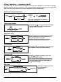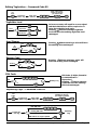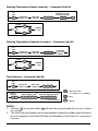
1
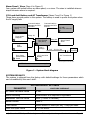
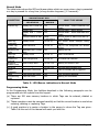
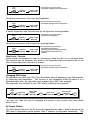
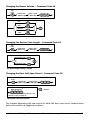
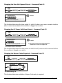
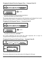
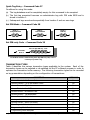
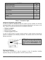
FCC VERSION
IXP 100 SERIES
SINGLE-DOOR ACCESS CONTROL SYSTEMS
SYSTEM 101
-
IXP901-1-0-GB-XX
USER MANUAL
Manual ref number: IXP300-0-0-GB-02
Issue 3
November 2001
IMPORTANT NOTICE
Although all efforts have been made to make this manual as accurate as possible, Impro Technologies
(Pty) Ltd does NOT accept any liability for errors or omissions. The data contained in this manual
supersedes any other information published on the product. We further reserve the right to amend or
improve the equipment and manual without notice.
GUARANTEE / WARRANTY
Impro Technologies (Pty) Ltd warrants that the Products furnished under this agreement will be free
from material defects in material and workmanship for a period three years from the date of
shipment. The Customer shall provide notice to Impro Technologies (Pty) Ltd of each such defect
within one week after the Customer's discovery of such defect. The sole obligation and liability of
Impro Technologies (Pty) Ltd under this warranty shall be to repair or replace at Impro's sole
discretion, but without cost to the Customer, the product or part which is so defective and as to which
such notice is given.
Upon request by Impro Technologies (Pty) Ltd, the product or part claimed to be defective shall
immediately be returned at the Customer's expense to Impro Technologies (Pty) Ltd. Replaced or
repaired products or parts will be shipped to the Customer at the expense of Impro Technologies (Pty)
Ltd.
There shall be no warranty or liability for any products or parts which have been subject to misuse,
accident, negligence, failure of electric power or modification by the Customer without Impro
Technologies (Pty) Ltd written approval. Final determination of warranty eligibility shall be made by
Impro Technologies (Pty) Ltd. If a warranty claim is considered invalid for any reason, the Customer
will be charged for services performed and expenses incurred by Impro Technologies (Pty) Ltd in
handling and shipping the returned item.
As to replacement parts supplied or repairs made during the original warranty period, the warranty
period of the replacement or repaired part shall terminate with the termination of the warranty period
with respect to the original product or part.
As Impro Technologies (Pty) Ltd has no control over where the product is used, or how it is installed,
no liability for ANY consequential damages can be accepted, whether due to malfunction, design,
deficiency, implementation or any cause whatsoever.
Impro Technologies does not guarantee interfacing compatibility of any of its equipment with any
third-party equipment, regardless of any standards which may be applicable. Connecting third-party
equipment to any Impro equipment may compromise the functionality of the Impro equipment and
render it inoperative.
THE FOREGOING WARRANTY CONSTITUTES IMPRO TECHNOLOGIES (PTY) LTD SOLE LIABILITY AND
THE CUSTOMERS SOLE REMEDY WITH RESPECT TO THE PRODUCTS AND IS IN LIEU OF ALL OTHER
WARRANTIES, LIABILITIES AND REMEDIES EXCEPT AS THUS PROVIDED, IMPRO TECHNOLOGIES
(PTY) LTD DISCLAIMS ALL WARRANTIES, EXPRESS OR IMPLIED, INCLUDING ANY WARRANTY OF
MERCHANTABILITY OR FITNESS FOR A PARTICULAR PURPOSE.
This product is designed
and manufactured by:
R
47 Gillitts Road
Pinetown
South Africa 3610
P O Box 15407
Westmead
South Africa 3608
© November 2001 Impro Technologies
Data subject to change without notice
(031)
700-1087
(031)
700-1511
(e-mail)
[email protected]
Page 2
IXP 100 SERIES System 101 USER MANUAL
CONTENTS
IMPORTANT NOTICE..........................................................................................2
GUARANTEE / WARRANTY ..................................................................................2
INTRODUCTION ................................................................................................5
THE USE OF THIS MANUAL .................................................................................6
SPECIAL TERMS USED IN THIS MANUAL...............................................................6
GENERAL DESCRIPTION .....................................................................................7
SYSTEM DESCRIPTION.......................................................................................7
Overview ...................................................................................................7
Door Entry Unit...........................................................................................8
Door Control Unit........................................................................................8
Door Strike /Maglock ...................................................................................8
RTE Button ................................................................................................8
Alarm Panel/Siren .......................................................................................9
12V Lead Acid Battery and AC Transformer.....................................................9
SYSTEM DEFAULTS..............................................................................................9
MODES OF OPERATION ..................................................................................... 10
Hardware Modes....................................................................................... 10
Intrusion Mode ......................................................................................... 10
Alarm Mode ............................................................................................. 11
ALARM MODE OPERATION............................................................................... 11
SYSTEM MODES ....................................................................................... 11
Normal Mode............................................................................................ 12
Programming Mode................................................................................... 12
GENERAL OPERATION...................................................................................... 13
PIN Codes, Reason Codes & Access Levels.................................................... 13
PIN Modes ............................................................................................... 14
USE OF FLOW DIAGRAMS TO DESCRIBE OPERATIONS ......................................... 14
Alarm Disarming PIN Code/Supervisor Unlock ............................................... 15
Arming the Alarm/Supervisor Lock............................................................... 15
Use of Reason Codes................................................................................. 16
Tag Presented – Arming / Disarming............................................................ 16
Tag Presented – Access ............................................................................. 17
Incorrect PIN Code Entry ........................................................................... 17
Door Forced/Door Open/Door Not Opened.................................................... 17
Special Function Mode (Long Duration Keypress)........................................... 18
Alarm Arming/Supervisor Lock .................................................................... 18
Relaxed/Enforced PIN codes....................................................................... 19
Status LED Quieting .................................................................................. 19
Tag Suspension ........................................................................................ 19
Door Lock/Unlock...................................................................................... 20
Changing PIN Codes.................................................................................. 20
AC Power Failure ...................................................................................... 20
Entering Programming Mode....................................................................... 21
PROGRAMMING MODE ..................................................................................... 21
General Editing Functions ................................................................................ 21
© November 2001 Impro Technologies
Data subject to change without notice
Page 3
Adding Tagholders – Command Code 01............................................................ 22
Editing Tagholders - Command Code 02 ............................................................ 23
Replacing Tags - Command Code 03 ................................................................. 23
Deleting Tagholders (Known Location) - Command Code 04 ................................. 24
Deleting Tagholders (Unknown Location) – Command Code 05 ............................. 24
Time Patterns - Command Code 06................................................................... 24
Changing Alarm Modes – Command Code 07...................................................... 25
Replacing Tags (Old Tag Available) – Command Code 08 ..................................... 25
Deleting the Transaction Table - Command Code 10............................................ 25
Changing the Relay #1 (Latch) Drive Time - Command Code 11............................ 26
Changing the Relay #2 (Alarm) Drive Mode & Time - Command Code 12 ............... 26
Configuring the Real Time Clock - Command Code 13.......................................... 27
Changing the Black-listed Tag Timeout Period - Command Code 14 ....................... 27
Changing the Present Tag Timeout Period - Command Code 15 ............................ 27
Changing the Key Entry Timeout Period - Command Code 16................................ 28
Changing the Alarm Ready Input Sensing - Command Code 17 ............................. 28
Changing the Buzzer Volume - Command Code 18 .............................................. 29
Changing the Reason Code Length - Command Code 19 ...................................... 29
Changing the Door Left Open Period - Command Code 20.................................... 29
Changing the Door Not Opened Period - Command Code 21................................. 30
Changing the AC Power Fail Alarm Period - Command Code 22 ............................. 30
Changing the Reason Codes Required - Command Code 23 .................................. 30
Changing the Special Function Keypress Time - Command Code 24 ....................... 31
Changing the No Keypress Timeout – Command Code 25..................................... 31
Changing the Request to Exit Input Sense – Command Code 26............................ 31
Quick Tag Entry - Command Code 27................................................................ 32
Set PIN Mode – Command Code 28................................................................... 32
Set PIN-only Code - Command Code 29............................................................. 32
TRANSACTION TYPES ........................................................................................... 32
INSTALLER TECHNICAL FUNCTIONS ....................................................................... 33
Deleting the Database..................................................................................... 33
Replacing the DEU.......................................................................................... 34
Restore Factory Defaults.................................................................................. 34
Firmware Upgrade of the DCU.......................................................................... 34
PC Software Configuration ............................................................................... 34
TAGHOLDER RECORD ........................................................................................... 34
DIAGRAMS
Figure 1 : System block diagram ...............................................................................9
TABLES
Table 1 : DEU/PC Functions......................................................................................6
Table 2 : System Default Settings............................................................................ 10
Table 3 : Intrusion Mode of Operation ..................................................................... 11
Table 4 : Alarm Mode Operation ............................................................................. 11
Table 5 : LED/Buzzer Indications in Normal Mode...................................................... 12
Table 6 : Special Function Keys............................................................................... 18
Table 7 : Transaction Types ................................................................................... 33
Table 8 : User Tag Record Table............................................................................. 35
© November 2001 Impro Technologies
Data subject to change without notice
Page 4
INTRODUCTION
The IXP 100 Series is a high-security access control system, intended to control the access
of up to 500 users through a single door.
Instead of a normal mechanical key, the door can only be opened from the outside when a
valid Tag is presented to the unit. Advanced security features prevent the door latch being
operated from the outside even if the wiring is tampered with, and even if the outside unit
is substituted with another unit.
The advantage of using a Tag is that if a Tag is lost, details of the Tag can be removed
from the system, and there is no need to change door locks.
For added security, the system can be programmed so that, in addition to presenting a
Tag, a 4-digit personal identification number [PIN] is also required to be entered via the
keypad before access is allowed.
Three Tagholder levels are provided for:
LEVEL
LIMITATIONS
User
May enter during specified time periods only.
Supervisor
May enter at all times.
Administrator
As for Supervisor but is also able to programme the system.
The system comprises three major components:
• Door Entry Unit (DEU).
• Door Control Unit (DCU).
• PC Software.
To provide a variety of features while keeping the system easy to use, certain advanced
functions and facilities are not selectable using the keypad unit. These functions are only
selectable by means of the PC software program.
For typical installations where these more advanced facilities are not required, the use of a
PC is not necessary, and the basic set-up can be performed using the Keypad DEU if the
default settings need to be changed.
The system is programmed at the factory to provide certain default functions.
Table 1 shows the different functions which can be performed using the PC or the Keypad
DEU on its own.
© November 2001 Impro Technologies
Data subject to change without notice
Page 5
FUNCTION
DEU
PC
Add/Edit/Delete Tags.
Yes
Yes
Set basic system parameters (e.g. Buzzer volume).
Yes
Yes
Keep short term records of events (Last 500 events).
Yes
Yes
Keep long term records of events.
No
Yes
Set advanced system parameters (e.g. Transaction Types).
No
Yes
Table 1 : DEU/PC functions
THE USE OF THIS MANUAL
This manual will help you to make any changes necessary to the system settings for the
IXP 100 Access Control System. The changes are all made by pressing keys on the Keypad
Door Entry Unit (DEU) which is mounted on the outside of the door in your building. The
response of the system to changes which you make is indicated visually (via the light
(LED) in the DEU) and audibly (via the buzzer in the DEU).
If you have a PC, then these changes can be made using the IXP 100 Series Software
which must be installed on the PC. You will find that using the PC for this will be easier
than using the keypad. The use of the PC software is described in the IXP 100 Series
Software Manual.
SPECIAL TERMS USED IN THIS MANUAL
Some special terms are used in this manual. In order to operate your IXP 100 Series
System you will need to be familiar with these terms. There is no need to learn these
definitions; you can simply refer to the explanations given when necessary. The terms are
explained below.
TERM
DESCRIPTION
Administrator
:
As per Supervisor, but is also able to program the system.
Alarm Panel
:
A separate alarm system connected to the IXP 100 system.
Arming
:
Setting the alarm system into its operational state.
Client's staff
:
Persons employed by the owner of the system.
Configurable
:
Can be changed by the client.
Default
:
The factory setting for an operation, which can be modified by
the client.
Disarming
:
Setting the alarm system into its non-operational state.
Flag
:
The word “flag” indicates that a condition is enabled,
permitting a related operation to be performed.
Function
:
An operation which the system can perform.
© November 2001 Impro Technologies
Data subject to change without notice
Page 6
TERM
DESCRIPTION
Intrusion
:
Unauthorized entry.
Parameter
:
A quantity (for example a Mode or Time period) which may be
set to different values.
Present a Tag
:
Pass or hold a tag close to the DEU front panel.
Reason Code
:
A code which indicates the reason for access.
Supervisor
:
A tagholder authorized to enter at all times.
Time Pattern
:
Entry control periods.
Transaction
:
Presentation of a tag and the system response to this.
Transaction Buffer
:
Storage of transaction information.
Transaction Data
:
Transaction information.
Transaction Event
:
Detection of a transaction.
User
:
Person issued with a tag for access purposes only.
Valid Tag
:
A tag which has previously been entered into the system
database and is not black-listed.
IMPORTANT NOTE
UNTIL YOU BECOME FAMILIAR WITH THE IXP 100 SYSTEM, YOU MAY ENCOUNTER
PROBLEMS IN SETTING UP THE SYSTEM OR IN MAKING CHANGES TO THE SETTINGS. IF
SO, PLEASE CONTACT YOUR LOCAL IMPRO DISTRIBUTOR. YOUR DISTRIBUTOR’S
DETAILS CAN BE OBTAINED FROM THE DEALER FROM WHOM YOUR SYSTEM WAS
PURCHASED.
GENERAL DESCRIPTION
SYSTEM DESCRIPTION
You will need an understanding of the parts which make up the system, and the way in
which the system operates to :
•
make sure that the system does what your company requires when it is first installed.
•
be able to alter tag information.
•
make any later changes to the system settings that you require. (in other words to
administer or supervise the IXP 100 System).
This section provides this description.
Overview
A block diagram (a diagram which shows how the parts of the system are connected
together) is given in Figure 1.
© November 2001 Impro Technologies
Data subject to change without notice
Page 7
Door Entry Unit (Item A in Figure 1)
Three types of Door Entry Unit (DEU) are available, but this manual applies only to the IXP
100 System 101, which uses the Keypad Door Entry Unit.
The Keypad DEU has the following operating features :
• It is able to detect tags.
• The keypad is used to make changes to the system programming.
• The keypad can be used to enter Personal Identification Numbers (PIN numbers).
• The keypad can also be used to enter Reason Codes.
• A buzzer to provide information to the user by means of different combinations of
beeps.
• A light (an LED) to provide information to the user by means of different length
flashes of different colors.
The DEU and the Door Control Unit (DCU) communicate with each other. For example,
when a tag is presented to the DEU, the tag ID is sent to the DCU, which searches its
memory to decide whether that tag is allowed access at the time. This information is then
sent to the DEU, which then causes the DEU buzzer to sound and the DEU LED to be lit to
tell the tagholder, for example, that the system will allow/disallow him entry.
The Door Control Unit (Item E in Figure 1)
This unit is the intelligent part of the system. It contains the program that governs the way
the system functions. This program is loaded into the unit at the factory with a default
program that provides functions suitable for most typical installations. The default
functions can be altered using the keypad in the DEU (as described in this manual) or by
using the IXP Software loaded onto a PC (item G in Figure 1) as described in the IXP 100
System Software User Manual.
The DCU provides the following functions:
• It accepts data from the DEU, and controls the operation of the buzzer and LED in the
DEU.
• It controls the operation of the Door Strike/Maglock (item B in Figure 1), which is the
door locking mechanism on the door controlled by the system.
• When the “Request to Exit” pushbutton (item C in Figure 1) is pressed, the DCU
responds by causing the Door Strike/Maglock to open.
• The system can be connected so that a Door Open Sensor indicates to the DCU that
the door is open, or so that an alarm indication from an Alarm Panel is fed to the DCU
(item D in Figure 1). Information about how your system is connected should be
available at your site.
• The system is normally powered from an AC transformer (item I in Figure 1).
Door Strike/Maglock (Item B in Figure 1)
This the special door lock which is controlled by the IXP 100 system.
RTE Button (Item C in Figure 1)
This the “Request to Exit” pushbutton which is normally located at a point close to the
door, and allows manual opening of the door from the secure side.
© November 2001 Impro Technologies
Data subject to change without notice
Page 8
Alarm Panel / Siren (Item H in Figure 1)
Your system will include either an alarm panel, or a siren. The siren is installed where a
simple intrusion alarm is required.
12V Lead Acid Battery and AC Transformer (Items F and I in Figure 1)
These items provide power to the system. The battery is used to power the system when
the AC supply fails.
Door Entry Unit
(DEU)
A
Door Strike/
Maglock
Communications
between the DCU
and PC.
Communications
between the DCU
and DEU.
Relay # 1
B
Relay # 2
Door Control
Unit (DCU)
E
RTE
Button
D
Alarm Panel/
Siren
H
13.8 V
Charge
Input #2
C
Door Open
Sensor/Alarm
Panel
PC with
IXP 100 Software
G
14 V - 18 V AC 2A
12 V Lead Acid
Battery
Input #1
MAINS
POWER
AC Transformer
F
I
IXP 100 System Overview.wmf
NOTE : Shaded boxes are Impro-supplied
Figure 1 : System block diagram
SYSTEM DEFAULTS
The system is shipped from the factory with default settings for those parameters which
can be modified by the user's staff.
SYSTEM DEFAULT SETTINGS
FACTORY DEFAULT
PARAMETER
AC Power Fail Alarm Period
5 min.
Alarm Disarming
Administrator and Supervisor tagholders.
Blacklisted Time-out Period
0030 (0 hours 30 minutes).
Buzzer Volume
Level 3.
Time Pattern
Allows access 24 hours per day, 7 days per week.
Door Left Open Period
0 s / not active.
© November 2001 Impro Technologies
Data subject to change without notice
Page 9
SYSTEM DEFAULT SETTINGS
FACTORY DEFAULT
PARAMETER
Door Not Open Period
0 s / not active.
Key Entry Time
60 seconds.
No Key Entry Timeout Period
120 seconds (requires tag presentation to reactivate).
Mode of Operation
Intrusion Mode.
Present Tag Timeout Period
10 seconds.
Reason Code Entry
Disabled.
Reason Code Length
2 digits.
Relay#1 (Latch) Drive Time
30 (3 seconds).
Relay#2 (Alarm Drive Time)
300 (30 seconds).
Tagholder Level
0 (User).
Time and Date
01 January 2000.
Time Patterns
Start Time = 00H00, Duration = 24H00 for every day
of the week.
Table 2 : System default settings
MODES OF OPERATION
Four Modes of operation are provided in the system. Of these, two are DCU Hardware
Modes (see "Hardware Modes") and two are System Modes (see "System Modes").
Hardware Modes
The DCU operates in one of two hardware modes :
• Intrusion Mode.
• Alarm Mode.
The changing of hardware modes can only be performed by the Administrator tagholder
(refer to the paragraph "Programming Mode").
Intrusion Mode
The Intrusion Mode can be used where there is no installed alarm panel and a simple
intrusion alarm is required. In this mode the Relay #2 is used to activate a siren when the
Door Open Sensor is triggered and the unit has been Armed. Arming will only be
permitted in normal operation if the Door Open Sensor is in the correct state.
Additional contact sensors can be connected in series or parallel to Input #1 to extend this
function beyond the access door alone to other doors. The normally open or normally
closed state can be set by the Administrator (refer to the installer for further information).
The siren activation period which applies when the alarm has been triggered can also be
set by the Administrator.
© November 2001 Impro Technologies
Data subject to change without notice
Page 10
Intrusion Mode – No Installed Alarm Panel
Relay #1 (LATCH)
Operates the Door Strike
Relay #2 (ALARM)
Operates the Siren
Input #1 (SEN)
From the Door Open Sensor
Input #2 (RTE)
From the Request to Exit Pushbutton
Table 3 : Intrusion Mode of Operation
Alarm Mode
The Alarm Mode is used where there is an installed alarm panel.
Alarm Mode – Use in conjunction with installed Alarm Panel
Relay #1 (LATCH)
Operates the Door Strike
Relay #2 (ALARM)
Connected to Alarm Panel for Arm / Disarm
Input #1 (RDY)
From the Alarm Panel “Ready” Status Input
Input #2 (RTE)
From the Request to Exit Pushbutton
Table 4 : Alarm Mode Operation
ALARM MODE OPERATION
Operation in the Alarm Mode is only possible if an Alarm Panel has been installed in your
system. In this case, Arming / disarming can be controlled by relay#2 in the DCU.
Input #1 is used to sense the “Ready” state of the Alarm Panel as the alarm cannot
normally be Armed unless it is “Ready”. This “Ready” state is represented by the LED
mode of the DEU and will prevent Arming if not “Ready”.
SYSTEM MODES
The system operates in one of two modes, namely Normal Mode and Programming Mode :
[a] The Normal Mode of operation is the default mode in which the DEU allows access
and Reason Codes to be entered together with the presentation of a tag. Audio and
visual indications for the various conditions which can occur in the Normal Mode are
described in Table 1.
[b] The Programming Mode is entered under control of the Administrator tagholder
and allows for the management of tag tables, settings, and operational parameters.
The Programming Mode requires the use of the DEU, so that access control is not
possible while in this mode.
© November 2001 Impro Technologies
Data subject to change without notice
Page 11
Normal Mode
The table below shows the LED and buzzer states which can occur when a tag is presented
or a key is pressed for a long time (a long duration keypress) (1-3 seconds):
CONDITION
INDICATION AT DEU
LED STATUS
Present Tag
Valid Tag
Presented
Invalid Tag
Presented
Awaiting PIN
Code
Valid PIN
Entered
Invalid PIN
Entered
Awaiting
Reason Code
Keypress
Alarm
Triggered
Fault
Programming
Mode
WHAT THIS MEANS
BUZZER
Steady Red + Blink Off
Off
Steady Green
Beep
Intermittent.
On for 1s
Slow Red Blink
On for 2s
Alternate Red / Green
Blink
Steady Green
Off
Normal Mode – Alarm Disarmed not
Ready.
Normal Mode – Alarm Armed.
Normal Mode – Alarm Disarmed and
Ready.
Normal Mode as above but with AC
Power Failure.
LED Green whilst Relay#1 being
driven.
Tag ID not recognised OR access
denied.
Waiting for PIN.
Steady Red
Steady Red + Green
Blink
Orange instead of Red
Off
Off
On for 1s
Valid PIN Received.
Fast Orange Blink
On for 2s
An invalid PIN received.
Slow Orange Blink
On for 0.2s
Waiting for Reason Code.
Red Flash Continuous
On for 0.1s
Off
Keypress acknowledge tone.
Flash to indicate alarm triggered.
Fast Red/Green Blink
Fast Red Flash
Off
Off
Fault condition detected.
Waiting for commands.
Table 5 : LED/Buzzer indications in Normal Mode
Programming Mode
In the Programming Mode, the facilities described in the following paragraphs can be
programmed into the system from the keypad .
(a) There are 500 user memory locations in which Tags can be entered, deleted or
replaced.
(b) These operations must be managed carefully so that the correct location is used when
entering, deleting or replacing Tags.
(c) A good practice is to assign a location to the person to whom the Tag was given.
Table 9 at the end of this manual will assist you with this.
© November 2001 Impro Technologies
Data subject to change without notice
Page 12
IMPORTANT NOTE
At least one tag must be given Administrator level in order to restrict access to
the Programming Mode. If no tag is given this level, any tag will allow access
to the Programming Mode. This would allow any user to program the system, with
possible disastrous consequences.
The Programming Mode can be used only if the DCU has been disconnected from the
PC.
GENERAL OPERATION
• The system will not allow access through the controlled door unless a valid tag (that
is, one that has been entered into the system) has been presented to the DEU.
•
•
If the system has been configured so that a PIN is required for the tag, this must be
entered within the Key Entry Time (this can be changed; the default is 60s) after the
tag is presented. If not, the system will deny access.
During the Armed status, automatic disarming occurs when an Administrator or
Supervisor tag is presented followed by a valid PIN Code.
In Normal Mode, the DCU waits either for a tag to be presented, or for a long duration
keypress to be detected :
•
•
•
Presenting a tag first indicates a request for access through the door, and the possible
entry of a Reason Code or PIN Code.
A long duration keypress, followed by a presented tag, followed by a PIN Code,
a special function such as entering Programming Mode (an Administrator level
tag is required for this).
The keypad becomes inactive after No Key Timeout (this is configurable by the
Administrator – the default is 120 s), and requires a tag to be presented to reactivate
it.
PIN Codes, Reason Codes & Access Levels
• A PIN Code must be setup for the Administrator and Supervisor level tagholders who
have the responsibility of alarm disarming.
•
•
The allocation of a PIN Code for User level tagholders is optional. This is done on a
per-tagholder basis for access control.
Only a single PIN Code can be assigned to a tagholder at any tag level.
•
The tagholder-selected PIN is used for normal door access (if required) and also for
the special function key operations (refer to “Special Function Key Operations”).
•
Any tag assigned a non-zero PIN Code when adding tags using the keypad, will be
required to use it for access whenever PIN codes are enforced (refer to “Special
Function Keys 2 and 3 ”).
If a PIN Code has been assigned to a tag for special function purposes and PIN Codes
are enforced but not required by that particular tag for normal access, then the PIN
Code requirement can only be relaxed for that tag using the PC Software (refer to the
IXP 100 Series Software Manual for details).
•
© November 2001 Impro Technologies
Data subject to change without notice
Page 13
•
Users can change but cannot delete their own PINs; they can only be deleted by an
Administrator.
PIN Modes
The IXP100 System offers the option of three PIN Modes. These PIN Modes operate in
conjunction with the Time Pattern Settings. The conditions for each PIN Mode are
described in the table below.
NOTE :
“Open” time periods are those periods when access is allowed for user
tagholders; “Restricted” time periods are those periods when access is only
allowed to Administrator and Supervisor tag levels.
Time Pattern
PIN Mode
Open
Restricted
All tags allowed.
Mode 1 Configurable PIN
Only Administrator/ Supervisor tags allowed.
PIN must be entered on presentation of a tag if a PIN has been set for that tag,
and if the PIN Enforced condition is set as part of the current Time Pattern.
All tags allowed. PIN not
required.
Mode 2 –
Restricted PIN
Only Administrator/ Supervisor tags allowed
access. PIN required if set for that tag.
The PIN Enforced/Relaxed Time Pattern setting is ignored in this Mode.
Mode 3 - PIN-only
All tags allowed. Global PIN
allows access even without
presentation of a tag.
Only Administrator/ Supervisor tags allowed
access. PIN required if set for that tag.
The PIN Enforced/Relaxed Time Pattern setting is ignored in this Mode.
USE OF FLOW DIAGRAMS TO DESCRIBE OPERATIONS
In the following text, use has been made of flow diagrams to show the sequence of
actions which have to be taken to complete various operations. For people not familiar
with flow diagrams, here is an explanation of how to use them. Real examples have been
used.
Example 1
Arming the Alarm / Supervisor Lock
This sequence arms the alarm in Alarm mode, or permits the Supervisor to lock the door
in Intrusion Mode.
For
4 sec.
0
Present a
valid Tag
This means that, in order to complete the operation of Arming the Alarm (for example),
the tagholder must :
© November 2001 Impro Technologies
Data subject to change without notice
Page 14
[1] Press the “0” key for 4 seconds.
[2] Present a valid tag.
Example 2
Deleting Tagholders (Known Location) – Command Code 04
Enter a table entry
number for the tag
you want to delete
For
4 sec.
#
Present the
Admin. Tag
Confirm
Enter valid
PIN Code
X X
#
1
#
Cancel
0 4 #
Deleting
a tag
0
To perform this function, the Administrator must :
[1] Press the “#” key for 4 seconds.
[2] Present the Administrator tag.
[3] Enter a valid PIN code, followed by the code 04#.
[4] Enter the table entry number relating to the tag to be deleted.
[5] Press the “#” key.
[6] The Administrator can then either :
(a) Press “1” to confirm the deletion, or
(b) Press “0” to cancel the deletion.
[7] After step 6(a) or 6(b), press “#” to cause the system to complete the required
action.
These principles apply to all the flow diagrams in this manual.
NOTE : The brochure “ A Quick Guide to Common IXP 100 Operations”, which uses these
diagrams is packed with your system for easy reference when you are performing the
more common operations.
Alarm Disarming PIN Code / Supervisor Unlock
The PIN Code for disarming the alarm (at Administrator and Supervisor level only) is the
normal access PIN Code which is allocated to their tags. The DCU memorises the Armed /
Disarmed state and therefore does not require a different PIN Code for disarming – this
function is performed automatically by the DCU.
Arming the Alarm / Supervisor Lock
This sequence arms the alarm in Alarm mode, or permits the Supervisor to lock the door in
Intrusion Mode.
© November 2001 Impro Technologies
Data subject to change without notice
Page 15
The Arming of the alarm is performed by the “Special Function Keypress” where the
tagholder :
For
4 sec.
0
Present a
valid Tag
It is therefore necessary for all User level tagholders who are authorised to Arm the Alarm
Panel to be assigned a PIN Code.
Use of Reason Codes
In certain applications it may be necessary for Reason Codes to be entered by a tagholder
as part of the access process.
A Reason Code is a two digit (default length) code that is entered after a tag has been
presented and the PIN Code (which is optional and can be required or not required by the
system setup) has been keyed in.
The Reason Code allocation is configured on a per tagholder basis (as per PIN Codes) and
forms part of the programming process when adding or editing a tag (this is an
Administrator level function).
If a Reason Code is required by the system, the DEU will prompt for entry of this code by
means of the LED and/or buzzer (see Table 2 for details) and the tagholder will be
required to enter the Reason Code within the Key Entry Time period (configurable
parameter – the default is 60s). Door access will only be granted once the Reason Code
has been entered.
Tag Presented – Arming / Disarming
Only authorised tagholders (Administrator & Supervisor) are able to Arm and Disarm the
alarm by means of their tag and PIN.
Alarm Arming for User tags can enabled / disabled on a per-tagholder basis when adding /
editing tags. Tagholders who are not authorised for disarming are prevented from
entering the premises once the alarm has been set (armed).
Indications given by the buzzer and LED indicate whether the alarm is Ready / Armed /
disarmed or triggered (refer to Table 2 for details).
If the system is in the Armed state, only the Administrator or Supervisor tag will be
accepted and the DEU will prompt for the PIN entry, followed by the entry of a Reason
Code (if required in your system).
Once the correct PIN has been entered, along with the Reason Code (if required), the DCU
will activate Relay#2 (according to its defined mode). If the hardware configuration mode
is the Alarm Mode, this will instruct the alarm panel to Disarm. The DCU will then activate
Relay#1 for the door strike according to the pre-configured parameters.
© November 2001 Impro Technologies
Data subject to change without notice
Page 16
In order to Arm the alarm (if the current alarm status is Disarmed), a Special Function
Keypress is used. A Special Function Keypress is the continuous pressing of a key for a
period of 4 seconds.
Tag Presented – Access
The system first establishes whether the alarm is Armed or Disarmed according to the
internal state of the DCU.
If the internal alarm status is Disarmed when a tag is presented, the Relay#1 will be
activated as above for both Administrator and Supervisor level tags with the exception that
the PIN Code is not mandatory. If a User tag is presented, the DCU will first check for a
valid Time Pattern.
The Time Patterns provide for a single access period on a per-day basis whereby access
will be granted to User level tagholders after tag presentation and a valid PIN Code (if
required in your system). The Time Pattern requires the entry of a start time and a
duration, which can be different for each day of the week.
Time Patterns can be entered / edited by the Administrator level tagholder only. The
default Time Pattern will allow access 24 hours per day, 7 days per week.
Incorrect PIN Code Entry
If a PIN Code is entered incorrectly three times in succession for a given tag, the tag will
be rejected for the pre-configured Blacklisted Tag Timeout Period (see “Blacklisted Tag
Timeout”).
The DCU maintains a table of up to 10 tags recording those with incorrect PIN Codes
having been entered. This table operates on a FIFO (first in, first out) basis. The
blacklisting status of a Tag is cleared by an Administrator editing the Tag data.
Door Forced / Door Left Open / Door Not Opened
The system can sense whether the door was not closed after a normal access, whether
the door was not opened after a normal access, or whether the door was forced without a
normal access. (This applies to Intrusion Mode only where the door sensor is connected
directly to the DCU – check whether this is the case for your system).
A Door Not Closed Event will be indicated after the Door Not Closed period (this is a
configurable parameter, with a default of 0s / not active) has expired and the door sensor
continues to indicate an open status. This event will result in an appropriate transaction
and will be indicated by the buzzer sounding rapidly for 10 s or until the door is closed.
A Door Not Opened Event will be indicated if the door has not been opened before the
Door Not Opened period (configurable parameter – default 0 s / not active) has expired.
This event will result in an appropriate transaction only.
A Door Forced Event will be automatically indicated as a transaction when the door open
sensor activates without a valid preceding transaction. If the alarm is Armed, this will
© November 2001 Impro Technologies
Data subject to change without notice
Page 17
automatically trigger the alarm. If the alarm is not Armed, this event will be indicated by
the buzzer sounding rapidly for 10 s or until the door is closed.
Special Function Mode (Long Duration Keypress)
The continuous pressing of a key for a period of 4 seconds (configurable parameter) will
cause the DCU to enter a Special Function Mode after a valid tag has been presented
followed by a valid PIN Code (Reason Codes are not applicable here).
The presentation of a valid tag must be made within 10 seconds (configurable parameter)
of pressing the key, and the PIN Code must be entered within Key Entry Time of
presenting the tag. The system must be in the Disarmed state.
Table 6 below identifies the special functions available :
Key
Description
0
Arm normally using any authorised tag and PIN.
1
Arm with bypass using Administrator or Supervisor tag and PIN.
2
Relax PIN Code on all tags – Administrator / Supervisor only.
3
Enforce PIN Code on all tags where configured – Administrator / Supervisor
only.
4
Toggle LED on/off at DEU during standby – Administrator / Supervisor only.
5
Suspend all Normal tags – Administrator / Supervisor only.
6
Resume all Normal tags – Administrator / Supervisor only.
7
Suspend all Supervisor tags – Administrator only.
8
Resume all Supervisor tags – Administrator only.
9
Toggle Door Locked / Unlocked – Administrator / Supervisor only.
*
Change tagholder PIN Code using valid tag and existing PIN.
#
I Administrator tag + valid PIN.
Table 6 : Special Function Keys
Alarm Arming / Supervisor Lock
Normal Arming of the alarm requires that the alarm is “Ready”. The status of Input #1 will
determine whether the alarm is Ready.
For
4 sec.
0
Present a
valid Tag
In this case a valid tag is any tagholder level with the appropriate Arm Authority flag set –
Administrator and Supervisor level tagholders have this flag set at all times and are thus
automatically authorised for Arming.
© November 2001 Impro Technologies
Data subject to change without notice
Page 18
Under certain circumstances it may be necessary to Arm the alarm with Bypass when it is
not Ready – it may be that the alarm panel has one zone with a known fault but Arming is
nevertheless required as the remaining zones are functional.
For
4 sec.
1
This function is restricted to Adminiatrator
and Supervisor level tagholder only.
Present a
valid Tag
On Arming, the keypad is disabled and the latch relay is deactivated if it is currently
active.
Relaxed / Enforced PIN Codes
This function relaxes the PIN Code entry requirement for normal access and is convenient
when a door is in frequent use and presentation of a tag is sufficient.
Relaxation of PIN Code entry on all tags:
For
4 sec.
2
This function can only be selected by
Administrator and Supervisor level tagholders.
Present a
valid Tag
Enter a valid
PIN Code
Normal operation of the PIN Codes:
For
4 sec.
3
This function can only be selected by
Administrator and Supervisor level tagholders.
Present a
valid Tag
Enter a valid
PIN Code
Status LED Quieting
In order to prevent the DEU from drawing attention to itself by means of the LED activity,
it is possible to set the status LED into a Quiet mode. The Quiet mode causes the status
LED to be in an off state whilst waiting for a tag to be presented or for a long duration
keypress.
For
4 sec.
4
The Quiet mode can only be toggeld by
Administrator and Supervisor level tagholders.
Present a
valid Tag
Enter a valid
PIN Code
In the event that the alarm has been triggered whilst in Intrusion Mode, the status LED
will override the Quiet mode and indicate the event in the usual manner.
Tag Suspension
Under certain circumstances it may be necessary to temporarily suspend all User level
tagholders.
© November 2001 Impro Technologies
Data subject to change without notice
Page 19
For
4 sec.
5
This function can only be access by
Administrator and Supervisor level tagholders.
Present a
valid Tag
Enter a valid
PIN Code
Cancel the suspension of the User level tagholders:
For
4 sec.
6
This function can only be access by
Administrator and Supervisor level tagholders.
Present a
valid Tag
Enter a valid
PIN Code
A similar suspension can be performed for all Supervisor level tagholders:
For
4 sec.
7
This function can only be access by
Administrator level tagholders.
Present a
valid Tag
Enter a valid
PIN Code
Cancel the suspension of the Supervisor level tagholders:
For
4 sec.
8
Present a
valid Tag
Enter a valid
PIN Code
This function can only be access by
Administrator level tagholders.
Suspending Supervisor level tagholders does
not automatically suspend User level
tagholders.
Door Lock / Unlock
Under certain circumstances it may be necessary to keep the door in an unlocked state.
This function can be accessed only when in the Disarmed state and resets back to the
Door Locked state when the alarm is Armed.
For
4 sec.
9
This function can only be access by
Administrator and Supervisor level tagholders.
Present a
valid Tag
Enter a valid
PIN Code
Changing PIN Codes
All tagholders can alter their PIN Code themselves without assistance from Administrator
or Supervisor level tagholders. This function is only accessible whilst the alarm is in a
Disarmed state; also, the tagholder must already have a PIN Code assigned.
The tagholder can configure a new PIN Code by following this sequence :
For
4 sec.
#
Present the
Admin. Tag
Enter a valid
existing
PIN Code
#
Enter a new
PIN Code
Enter the new
#
PIN Code
again
#
The new PIN Code will only be accepted and stored if both entries have been made
without error.
AC Power Failure
The DCU detects failure of the AC power and generates an audio / visual response at the
DEU after a disconnect period greater than 5 minutes (configurable parameter). The
© November 2001 Impro Technologies
Data subject to change without notice
Page 20
Green LED on the DCU flashes and the LED on the DEU changes from Red to Orange
immediately after a power failure. The buzzer will sound intermittently after 5 minutes.
The condition will clear automatically once the AC power has been restored.
A transaction will be logged for each AC power fail and restore.
Entering Programming Mode
In order to access the Programming Mode, the Administrator level tagholder must :
For
4 sec.
#
Present a
valid Tag
Enter a valid
PIN Code
The Programming Mode functions are described under “PROGRAMMING MODE”.
The Programming Mode is automatically exited if no key is pressed for a period of 60
seconds (this can be changed – see “Key Entry Time”).
PROGRAMMING MODE
All Programming Mode operations must be performed by an Administrator level tagholder.
General Editing Functions
When in Programming Mode, the following key sequences will be applicable throughout:
•
Pressing the * key once will clear the current programming function Ready for reentry of a parameter.
•
Pressing the * key twice in succession will exit out of the current programming
function and return to Programming Mode.
•
•
Pressing the * key three times in succession will exit out of programming mode
completely.
Pressing the # key will accept the current entry and proceed to the next step if the
entry is valid, indicated by a Green LED. The # will also accept the default value
automatically if a specific selection is not made.
•
Waiting for key entry indicated by fast flashing Red.
See next page
© November 2001 Impro Technologies
Data subject to change without notice
Page 21
Adding Tagholders – Command Code 01
A tag can only be entered into the system once, and any attempt to re-enter an existing
tag will result in an error response. Each tag occupies a single fixed entry in a tags table
and this entry point must be recorded manually by the Administrator.
Entering Programming Mode
For
4 sec.
yes
Keypad
active
no
#
Present
any Tag
Present
Administrator
Tag
1)
PIN
Code
0 1 #
1) When using a system the first time and having no
tags entered, any Tag will do
Table entry number
Pressing the * key once will clear the digits
entered and allow for the full table entry
number to be re-entered.
new
Table
entry
number
X X
Present
new Tag
#
Tagholder level
User
0
Supervisor
1
Administrator
2
Level
#
An incorrect entry will result in an error signal
and the Administrator will be required to reenter the tagholder level again.
Pressing # without entering a tagholder
level will accept the default level of 0.
Arm/Disarm
arm
to
allow
Tag
to
1
no arming
Pressing # without entering a value will cause
the system to accept the default settings.
#
#
Reason Code
yes
Pressing # without entering a value will
accept the default setting.
Once the above flags have been entered, the
system expects the Enable Reason Codes flag
(all expected key entries are indicated by a
fast-flashing Red LED)
1 #
Reason
Code
no
#
PIN Code
yes
X X X X #
PIN
Code
Editing a tag
no
PIN Code (4 Digits, Essential
for Administrator +
Supervisor)
#
© November 2001 Impro Technologies
Data subject to change without notice
Page 22
Editing Tagholders – Command Code 02
Enter a table entry
number for the tag
you want to edit
For
4 sec.
#
Present the
Admin. Tag
Enter valid
PIN Code
0 2 #
#
X X
Tagholder level
User
0
Supervisor
1
Administrator
2
Level
An incorrect entry will result in an error signal
and the Administrator will be required to reenter the tagholder level again.
Pressing # without entering a tagholder
level will leave the existing tagholder level
unchanged.
#
Arm/Disarm
arm
1
to
allow
Tag
to
Pressing # without entering a value will leave
the existing value unchanged.
#
no arming
#
Reason Code
yes
Pressing # without entering a value will
leave the existing value unchanged.
1 #
Reason
Code
no
#
PIN Code
yes
PIN Code (4 Digits, Essential
for Administrator +
Supervisor)
Pressing
#without entering
a PIN will leave the existing
PIN Code unchanged.
X X X X #
PIN
Code
Editing a tag
#
no
Replacing Tags – Command Code 03
Enter a table entry
number for the tag
you want to replace
For
4 sec.
#
Present the
Admin. Tag
Enter valid
PIN Code
new PIN Code
Present the
new Tag
0 3 #
X X X X
existing PIN Code
#
PIN Code is no longer required
© November 2001 Impro Technologies
#
X X
Replacing
a tag
*
Data subject to change without notice
Page 23
Deleting Tagholders (Known Location) – Command Code 04
Enter a table entry
number for the tag
you want to delete
For
4 sec.
#
Present the
Admin. Tag
Confirm
Enter valid
PIN Code
X X
#
1
#
Cancel
0 4 #
Deleting
a tag
0
Deleting Tagholders (Unknown Location) – Command Code 05
For
4 sec.
#
Present the
Admin. Tag
Confirm
Enter valid
PIN Code
Present the
tag to be
deleted
1
#
Cancel
0 5 #
Deleting
a tag
0
Time Patterns – Command Code 06
For
4 sec.
#
Present the
Admin. Tag
Enter valid
PIN Code
0 6 #
D
Day of
the week
D #
Enter the Start Time
1)
H H M M #
1)
Enter the required Duration
H H M M #
1) 24 hour clock format
... Day of the week
1 = Sunday to 7 = Saturday
H
... Hour
M
... Minute
NOTES:
1. Pressing * at any time before # will clear the previous keystrokes (if any) to allow
for re-entry.
2. The Start Time and Duration will be automatically checked for validity and will result in
an error response (a slow Red LED blink and activation of the buzzer for 2 seconds) if
incorrect.
© November 2001 Impro Technologies
Data subject to change without notice
Page 24
The following rules apply to the time zones:
(a) Tag access is granted during the period from the Start time through the length of the
Duration time.
(b) If the combination of the Start time and the Duration extend into the following day,
then this will override the Start time set for the following day.
The default time patterns will be Start Time = 00H00, Duration = 24H00 for every day of
the week.
Changing Alarm Modes – Command Code 07
For
4 sec.
#
Present the
Admin. Tag
Alarm Mode
Enter valid
PIN Code
0 7 #
1
#
Intrusion Mode
(default mode)
0
Replacing Tags (Old Tag Available) – Command Code 08
For
4 sec.
#
Present the
Admin. Tag
Enter valid
PIN Code
0 8 #
Present the
old Tag
Present the
new Tag
Checking will be performed to ensure that the new tag is not a duplicate tag in the tags table.
Deleting the Transaction Table – Command Code 10
For
4 sec.
#
Present the
Admin. Tag
Enter a valid
PIN Code
Confirm
1 0 #
1
Re-enter their
PIN Code
#
Cancel
(with any other digits)
X
This function will serve the purpose of clearing the tags transaction
buffer of all entries.
© November 2001 Impro Technologies
Data subject to change without notice
Page 25
Changing the Relay#1 (Latch) Drive Mode and Time – Command Code 11
For
4 sec.
#
Present the
Admin. Tag
Enter a valid
PIN Code
Set relay to toggle mode
Set relay to pulse mode
1 1 #
1
0 #
Entry of the
activation period
#
X X X X
The relay activation period in 0.1 second units with a range of
0 to 9999. The default activation period will be 30 (3 seconds).
A value of 0 will be interpreted as activate relay whilst tag is being presented. The entry
of the activation period must be followed by # and can be cleared by pressing * .
Changing the Relay#2 (Alarm) Drive Mode & Time – Command Code 12
For
4 sec.
#
Present the
Admin. Tag
Enter a valid
PIN Code
1 2 #
If the unit in the Alarm Mode (refer to "Modes of Operation"):
Set Toggle on Arm/Disarm
1
Alarm Mode
Set Pulse on Arm/Disarm
0 #
Entry of
the pulse
duration
#
X X
The relay activation period in 0.1 second units with a range of
1 to 99. The default activation period will be 5 (0.5 seconds).
If the unit in the Intrusion Mode (refer to "Modes of Operation"):
Intrusion Mode
Entry of the siren
activation period
X X X X
#
The relay activation period in 0.1 second units with a range of
1 to 9999. The default activation period will be 300 (30 seconds).
© November 2001 Impro Technologies
Data subject to change without notice
Page 26
Configuring the Real Time Clock – Command Code 13
For
4 sec.
#
Present the
Admin. Tag
Enter a valid
PIN Code
1 3 #
1)
Enter the date in the format
Enter the time
Y Y M M D D #
H H M M #
1) 24 hour clock format
Y
M
D
H
M
... Year
... Month
... Hour
... Minute
... Day
The system will check the validity of the time and date and issue an error response if not
valid. A valid time and date will reset the real time clock. The default time and date will
be 01 January 2000.
Changing the Blacklisted Tag Timeout Period – Command Code 14
For
4 sec.
#
Present the
Admin. Tag
Enter the period
Enter a valid
PIN Code
1 4 #
1)
H H M M #
1) The period for which tags will be Blacklisted after
incorrect PIN entry.
H
M
... Hour
... Minute
The time period will be checked for validity after entry. This will prevent the tag from
being accepted for the specified duration. The default value is 0030 (0 hours 30 minutes),
with a maximum of 2400 (24 hours).
Changing the Present Tag Timeout Period – Command Code 15
For
4 sec.
#
Present the
Admin. Tag
Enter a valid
PIN Code
1)
Enter the period
1 5 #
S
... Second
S S S #
1) The default value is 10 seconds with range
between 3 and 255 seconds.
© November 2001 Impro Technologies
Data subject to change without notice
Page 27
This parameter defines the period within which a tag must be presented after being
prompted by the system. This parameter is applicable throughout where a tag is required
to be presented.
Changing the Key Entry Timeout Period – Command Code 16
For
4 sec.
#
Present the
Admin. Tag
Enter the period
1 6 #
Enter a valid
PIN Code
S
1)
S S #
... Second
1) The default value is 30 seconds with a range
between 3 and 60 seconds.
This parameter defines the period within which a PIN or Reason code must be entered
after being prompted by the system. This parameter is applicable throughout where a PIN
or Reason code is required to be presented
Changing the Alarm Ready Input Sensing – Command Code 17
For
4 sec.
#
Present the
Admin. Tag
Enter a valid
PIN Code
1 7 #
If the unit in the Alarm Mode (refer to "Modes of Operation"):
Active sense state: Low Voltage or
Contact closed
1
Alarm Mode
#
Active sense state: High Voltage or
Contact open
0
This mode allows fo configurable interfacing to the Ready indicator
of the alarm panel.
If the unit in the Intrusion Mode (refer to "Modes of Operation"):
Active sense state: Low Voltage or
Contact closed
0
Intrusion Mode
#
Active sense state: High Voltage or
Contact open
1
This mode allows for configurable interfacing to normally open or
normally closed sensor circuit, or a voltage type trigger circuit.
Input #1 operates according to the selected Alarm Mode or Intrusion Mode and the
required mode must be selected prior to configuring Input #2.
© November 2001 Impro Technologies
Data subject to change without notice
Page 28
Changing the Buzzer Volume – Command Code 18
For
4 sec.
#
Enter a valid
PIN Code
Present the
Admin. Tag
Off
0
Soft
1
Medium
2
Loud
3
1 8 #
#
The default volume setting is 3.
Changing the Reason Code Length – Command Code 19
For
4 sec.
#
Present the
Admin. Tag
Enter a valid
PIN Code
The Reason Code
length is 1 digit
1
The Reason Code
length is 2 digits
2
1 9 #
#
The default length setting is 2 digits.
Changing the Door Left Open Period – Command Code 20
For
4 sec.
#
Present the
Admin. Tag
Enter the period
Enter a valid
PIN Code
1)
2 0 #
S
... Second
S S S #
1) The period is entered in seconds between 0 and
255 where a value of 0 implies off.
The default value is 30 seconds.
This function determines the time period for which the door open sensor remains active
before the condition is flagged as an alarm.
© November 2001 Impro Technologies
Data subject to change without notice
Page 29
Changing the Door Not Opened Period – Command Code 21
For
4 sec.
#
Enter a valid
PIN Code
Present the
Admin. Tag
Enter the period
1)
2 1 #
S
... Second
S S S #
1) The period is entered in seconds between 0 and
255 where a value of 0 implies off.
The default value is 30 seconds.
This function determines the time period for which the door open sensor remains inactive
after a normal access before the condition is flagged as an alarm
Changing the AC Power Fail Alarm Period – Command Code 22
For
4 sec.
#
Enter a valid
PIN Code
Present the
Admin. Tag
1)
2 2 #
M
Enter the period
... Minute
M M #
1) The period is entered in minutes between 0 and
60 where a value of 0 implies off.
1) The period is entered in minutes between 0
and 60 where a value of 0 implies off.
The default value is 5 minutes.
This function determines the time period for which the AC power must be removed before
the condition is flagged as an alarm.
Changing the Reason Codes Required – Command Code 23
For
4 sec.
#
Present the
Admin. Tag
Reason Code will
be required
Enter a valid
PIN Code
2 3 #
1
#
Reason Code will
be not required
0
The default setting is 0.
This function determines whether a Reason Code entry is required.
© November 2001 Impro Technologies
Data subject to change without notice
Page 30
Changing the Special Function Keypress Time – Command Code 24
For
4 sec.
#
Present the
Admin. Tag
Enter the period
Enter a valid
PIN Code
1)
S
2 4 #
... Second
S S S #
1)
The period is entered in 0.1 seconds units with range between
20 and 100. The default value is 30 (3 seconds).
This function determines the time period for which the button on the keypad must remain
pressed before the condition is recognised as a special function keypress.
Changing the No Keypress Timeout – Command Code 25
For
4 sec.
#
Present the
Admin. Tag
Enter the period
Enter a valid
PIN Code
1)
S
2 5 #
... Second
S S S #
1)
The period is entered in seconds with range between
10 and 255. The default value is 120 seconds.
This function determines the time period after which keypresses will no longer be
recognised at the Keypad DEU until a tag is presented.
Changing the Request to Exit Input Sense – Command Code 26
For
4 sec.
#
Present the
Admin. Tag
will trigger on a
closed contact
Enter a valid
PIN Code
2 6 #
1
#
will trigger on
an open contact
0
The default setting will be 1.
This function determines the logic active state of the Request to Exit input.
© November 2001 Impro Technologies
Data subject to change without notice
Page 31
Quick Tag Entry – Command Code 27
Conditions for using this mode:
(a) The tag database must be completely empty for this command to be accepted.
(b) The first tag presented becomes an administrator tag with PIN code 9999 and is
stored in location 1.
(c) Subsequent tags are stored sequentially from location 2 and are user tags.
Set PIN Mode – Command Code 28
Mode 1 Configurable PIN
Mode 2 Restricted PIN
Mode 3 PIN only
1 #
2 #
3 #
Set PIN-only Code – Command Code 29
Enter 4-digit PIN-only Code
Select PIN
Mode 3
D D D D #
In this Mode access is allowed using the 4-digit PIN-only code; it is not
necessary to present a tag.
TRANSACTION TYPES
Table 4 identifies the various transaction types applicable to the system. Each of the
transaction types can be selected or de-selected via the PC software program in order to
optimise the transaction buffer memory. The following transaction types can be recorded
on tag presentation depending on the configuration of transactions:
CONDITION
DEFAULT
Access Granted – No Reason Code
On
Access Granted – Up to 99 Reason Codes
On
Access Denied – Tag Unknown
On
Access Denied – Invalid Time
On
Access Denied – No Reason Code
On
Access Denied – Tag Blacklisted
On
Access Denied – Suspended
On
Arming not Authorised
On
Arming Denied – Alarm not Ready
On
Disarming not Authorised
On
Programming Mode Denied
On
Programming Mode Accepted
On
© November 2001 Impro Technologies
Data subject to change without notice
Page 32
CONDITION
DEFAULT
Special Function Action
Off
Alarm Armed – Normal
On
Alarm Armed with Bypass
On
Alarm Triggered
On
Request to Exit
Off
Door Forced
On
Door not Opened
On
Door not Closed
On
Tamper
On
Power Up
On
AC Power Failed
On
Table 7 : Transaction Types
INSTALLER TECHNICAL FUNCTIONS
In order to provide for maintenance once the system has been installed, the following
technical functions can be performed without requiring Administrator level access or any
tags. These will normally be performed by an installation technician :
•
•
•
•
Deleting the database.
Replacing the DEU.
Restoring factory defaults
Firmware upgrade of the DCU
In order to restrict access to certain of these functions a unique security code must be
entered as indicated by the following instructions. This security code is the DCU Fixed
Address (see below).
Label
NOTE : The unique security code found
on a label on the relay inside the DCU is
used for some of these functions. This
unique code is the fixed address for the
DCU.
Deleting the Database
Under certain circumstances it may be necessary to clear all tagholders (including
tagholder settings) from the tags table in the DCU as shown below :
© November 2001 Impro Technologies
Data subject to change without notice
Page 33
The system
must be
switch off
Switch on the
main power
while pressing
until acknowledged by the
LED /buzzer
Enter the
security code
#
The tags database will then be deleted and the system will return to Normal mode.
NOTE : The security code is the DCU Fixed Address.
Replacing the DEU
In the event that either the DEU or DCU are replaced,
automatically.
re-matching will take place
The applicable unit will be replaced whilst power is removed from the system. Once the
new unit has been connected, the power must be turned on. The DCU will automatically
detect a communications failure with the DEU and interrogate the new unit for
authentication codes.
Restore Factory Defaults
Under certain circumstances it may be necessary to reset the system to its factory default
settings.
The DCU
must be
switch off
Switch on the
main power
together with
until acknowledge by the
LED /buzzer
Enter the
security code
#
The system defaults will be restored. The system will return to Normal mode.
Firmware Upgrade of the DCU
In order to implement a firmware upgrade of the DCU, the function must be initiated from
the PC software program.
PC Software Configuration
The following functions must be configured from the PC software and cannot be performed
via the DEU:
• Selection of transaction types for recording.
•
Calibration of real time clock (if applicable).
•
Definition of the database name (if applicable).
•
Setting the PIN-required status for individual tagholders.
TAGHOLDER RECORD
The User Tag Record Table (Table 8) on the following pages is to be used to record the
details of the tagholders stored in each memory location in the DCU database. We advise
you to make photo-copies of these pages and use these for your records.
© November 2001 Impro Technologies
Data subject to change without notice
Page 34
Table 8 – USER TAG RECORD TABLE
IXP 100 Access Control System
Unit identification
Location of unit
Administrator
Supervisor
LOCATION
NO.
ISSUED TO
© November 2001 Impro Technologies
LOCATION
NO.
ISSUED TO
Data subject to change without notice
Page 35
LOCATION
NO.
ISSUED TO
© November 2001 Impro Technologies
LOCATION
NO.
ISSUED TO
Data subject to change without notice
Page 36
LOCATION
NO.
ISSUED TO
© November 2001 Impro Technologies
LOCATION
NO.
ISSUED TO
Data subject to change without notice
Page 37
LOCATION
NO.
ISSUED TO
LOCATION
NO.
ISSUED TO
Table 8 : Tagholder Record Sheet
© November 2001 Impro Technologies
Data subject to change without notice
Page 38
USER'S NOTES
© November 2001 Impro Technologies
Data subject to change without notice
Page 39
FCC APPROVAL NOTICE
Warning :
Changes or modifications to these units not expressly approved
by the party responsible for compliance could void the user’s authority to
operate the equipment.
NOTE : This equipment has been tested and found to comply with the limits
for a Class B digital device, pursuant to Part 15 of the FCC Rules. These limits
are designed to provide reasonable protection against harmful interference in a
residential installation. This equipment generates, uses, and can radiate radio
frequency energy and, if not installed and used in accordance with the
instructions, may cause harmful interference to radio communications.
However, there is no guarantee that interference will not occur in a particular
installation. If this equipment does cause harmful interference to radio or
television reception, which can be determined by switching the equipment off
and on, the user is encouraged to try to correct the interference by one or more
of the following measures :
•
•
•
•
Reorient or relocate the receiving antenna.
Increase the separation between the equipment and the receiver.
Connect the equipment into an outlet on a circuit different from that to
which the receiver is connected.
Consult the dealer or an experienced radio TV technician for help.
Shielded cables must be used with these units to ensure compliance with the
Class B FCC limits.
APPLICABILITY OF THIS MANUAL
The last two digits of the standard Impro stock code indicate the issue status of the item
concerned. This manual is applicable to the IXP 100 Series System 101, stock code
IXP900-1-0-GB-00 onwards. The next issue of this manual will determine the final
equipment issue to which this manual issue is applicable.
Please advise us of any errors or omissions in this manual to enable
us to improve our service to you.
Thank you for choosing Impro products to implement your security or asset management
systems.
Impro Technologies design and manufacture a wide range of technically advanced, highquality, reliable Access Control and Asset Identification and Management Systems. Please
contact your distributor to find out more about our products, or advise us of your needs for
specialised products not yet in our extensive and continually expanding range.
IXP300-0-0-GB-02
Issue 3
November 2001
© November 2001 Impro Technologies
k:\Custman\ Ixp 100 series\
English Manuals\
ixp100_sys[FCC]-usrm-en-03.doc
Data subject to change without notice
Page 40