1
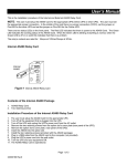
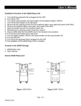
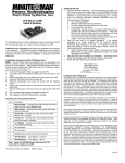
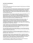
AMP-SOL-2 Series
Solenoid Amplifier
Users’ Manual
Servo Tech Inc
1747 W. Roosevelt Rd, Suite 110
Chicago, IL 60608
Ph: (312) 997-3733 Fax: (312) 997-3734
www.ServoTechInc.com
TABLE OF CONTENTS
1. The AMP-SOL-2 Series Solenoid Amplifier…………..….….………………………………3
1.1. Components of the Package……………………………………………………....3
1.2. Technical Specifications………………………………………………………….4
1.3. Hardware Requirements…………………………………………………….….…5
1.4. Connection Ports and Cables……………………………………………………..6
2. Installing Your AMP-SOL-2...………….……….……………………………………..…….8
2.1. How Does It Work………………….…………………………………….….…...8
2.2. How to Wire and Use it……………………………………………………….…..12
3. Contact Information………………………………………………………..………………..13
2
1. The AMP-SOL-2 Series Solenoid Amplifier
The AMP-SOL-2 Series Solenoid Driver board drives two proportional solenoids. The board
accepts digital pulse width modulated (PWM) input (0 –5V) or analog voltage (0-5V or 0-10V)
as current command signals. The output current is controlled by means of a switching technique
(25 kHz steady-state) allowing efficient operation. Each channel can provide up to 2A of
regulated current regardless of coil resistance. It accepts power supply voltages from 12V to
26V. An “OK/Fault” output signal alerts the user of short-circuit or open-circuit condition at the
load. Load short-circuit and open-circuit protection circuit disables the output and the driver
becomes functional only when power is recycled. Reverse polarity detection circuit disables the
power output stage when it detects reverse voltage polarity, but it does not change the state of
“OK/Fault” signal. The current through the solenoid can be monitored as an analog signal in the
0-10V range.
Features:
•
•
•
•
•
•
•
•
•
•
1.1.
Supply voltage range: 12V –26V.
Two channel output
Up to 2A/channel current capacity
Proportional output current control
Output current is regulated with current loop feedback
High frequency switching output (25 kHz)
Accepts both PWM (0V low, 5V high) and analog inputs (0-5V range, or 0-10 V range)
as current command. Jumper selected.
Load short-circuit shut-down
OK/Fault flag to indicate load short-circuit or open-circuit
Reverse polarity protected by turning OFF power output stage.
Components of the Package
1. AMP-SOL-2 Board (with two jumpers on JP3 and JP4 installed in default
positions)
2. Users’ Manual
3
1.2. Technical Specifications
Input Specifications
Power Supply
Current command (Input) Signal for each
one of two channels:
12-26 VDC
PWM1 and PWM2:
0-100%, 2 kHz to 20 kHz range,
Non-isolated, Low <0.8 V, High 5V,
TTL and CMOS compatible
Or
Analog 1 and Analog 2:
Analog voltage 0 V to 5 V
Or
Analog voltage 0 V to 10 V
Output Specifications
Maximum output current per channel
2 A per Channel
PWM Output: PWM1, PWM2
25 kHz switching frequency under steady
state.
Fault: Low
No Fault: High
OK/Fault (Load Short-Circuit/Open
Circuit)
OK/Fault 1 , OK/Fault 2
Current monitor output:
Current Monitor 1,
Current Monitor 2
0V-10V range corresponding to 0A to 2A
current output
General Specifications
Short Circuit protection
YES
Open Circuit protection
YES
Reverse Polarity protection
YES
Electrical Connection
Screw terminals, 12 - 16 AWG wire
Mechanical Dimensions
4.0” X 3.55”
Operating Temperature Range
-40 C to 85 C
4
1.3. Hardware Requirements
1. Power Supply: 12 V to 26 V
2. Current Command Signal: PWM (0-5V, 2 kHz-20 kHz, 0-100% duty cycle) or Analog
Source (0V to 5V or 0V to 10V).
3. Analog Signal Source 5V for Enable1/Enable2 signals.
5
1.4. Connection Ports and Cables
Connecter JP1
1
2
3
Connector#
1
2
3
4
5
6
4
5
6
Name
Input Voltage (12V – 26V)
Power Ground
Solenoid#1 High
Solenoid#1 Low
Solenoid#2 High
Solenoid#2 Low
Connector JP2
12 11 10
1
Connector#
1
2
3
4
5
6
2
3
9
8
7
4
5
6
Name
Analog Current Command 1
PWM Current Command 1
Enable Driver 2
PWM Current Command 2
Enable Driver 1
OK/Fault Status 2
7
OK/Fault Status 1
8
9
10
11
12
Analog Current Monitor 2
Analog Current Command 2
Ground
Analog Current Monitor 1
Ground
Description
Commands the current in Solenoid#1
Commands the current in Solenoid#1
Enables Driver#2 when high
Commands the current in Solenoid#2
Enables Driver#1 when high
Indicates a solenoid#2 open-circuit
or Short-circuit fault when low
Indicates a solenoid#1 open-circuit
or Short-circuit fault when low
Current in solenoid#2 (0 - 10 V)
Commands current in solenoid#2
Ground
Current in solenoid#1 (0 - 10 V)
Ground
6
Connectors: JP3 and JP4
1
3 5
1 3
5
2
4 6
2 4
6
• Shorting pins 1-2 configures solenoid current command as analog 0 to 5 V
• Shorting pins 3-4 configures solenoid current command as analog 0 to 10 V
• Shorting pins 5-6 configures solenoid current command as PWM
7
2. Installing Your AMP-SOL-2
2.1. How Does It Work
Fig 1: Block Diagram of AMP-SOL-2 Solenoid Driver Board
The AMP-SOL-2 solenoid driver board has two independent solenoid driver channels. The peak
current in each channel can be programmed separately through a current command input which
is proportional to a digital pulse width modulated input signal or an analog signal. Each channel
can be disabled/enabled through an enable input signal. A current sensing circuit maintains the
current irrespective of the fluctuations in the input power supply.
Two step-down voltage regulators (LM2937ET-10 and LM2937ET-5.0) generate 10V and 5V
required for control circuitry. The voltage regulators are reverse-polarity protected and turn-off
when reverse voltage is applied at its input. This in turn disables the driver chip.
By shunting different pins of Headers JP3 and JP4, current command signal can be configured to
be a PWM signal, analog signal in 0-5 V range or analog signal in 0-10 V range. The current
sense circuit uses a differential amplifier to detect the voltage across the current sense resistor in
series with the solenoid. The closed loop current switching logic inside the PWM driver
maintains the current in the solenoid equal to the commanded value. Under steady state the
output switching frequency is 25 kHz. The current monitor signals indicate the current through
the solenoids. A voltage of 10 V at the current monitor output corresponds to 2 A and 0V
8
corresponds to 0A.
Short-Circuit protection circuit monitors the current through the solenoid and disables the
channel, if a short is detected at the load. OK/Fault status signal will go low (high for normal
operation). Once the short at the output is removed, recycling power to the board enables the
driver. Open-Circuit detection circuit forces the OK/Fault status signal low if an open-circuit is
detected at the load.
The Driver block consists of ST Microelectronics solenoid driver chip L295 and associated
circuitry. It has two independent driver channels and is controlled by three digital inputs (chip
enable (EN), driver#1 enable (VEN1) and driver#2 enable (VEN2)) and two analog inputs (current
commands to program the solenoid currents, Vref1 and Vref2). When driver#1 is activated by low
level on EN input and high on VEN1, the output transistors of the driver circuit switch ON and
current rises through solenoid#1 (Refer to Fig.2). A current sense circuit within the driver chip
senses the current through the solenoid. When the solenoid current equals the current command
reference Vref1, the output transistors are switched OFF and the current in the solenoid starts to
decay. An internal oscillator fixed at 25 kHz, turns ON the output transistors at its next clock
pulse and the current in the solenoid rises again. When the solenoid current reaches Vref1 value,
the output transistors are again switched OFF. This process is repeated, regulating the solenoid
current until VEN1 goes low. The operation of driver#2 is same as above.
For detailed information on driver operation, refer to L295 (ST Microelectronics) datasheet.
9
Fig.2 Operation of L295 Driver
Signal Conditioning/Current Command selector block consists of a low pass filter and two
headers JP3 and JP4. Current command can be configured as PWM, analog 0-5 V range or
analog 0-10 V range, by choosing the jumper (JP3/JP4) configuration.
The PWM current command signal is passed through a second-order Sallen-Key low-pass filter
and a resistor voltage divider to generate current command (Vref1 and Vref2) in the 0-2 V range.
100% duty-cycle generates a current command of 2 A and 0% duty-cycle generates a current
command of 0 A. The analog commands are scaled down using a resistor voltage divider to
generate Vref1/Vref2 in the 0-2 V range. An analog input voltage of 5V/10V corresponds to 2 A
and 0V corresponds to a current command of 0 A.
A current-sense circuit senses the voltage across a current sense resistor in series with the
solenoid and amplifies it to 0-10 V range. A voltage of 10 V at the current monitor output
corresponds to 2 A and 0V corresponds to 0A.
Load Short-circuit protection block monitors the current through the solenoid and sets a D flipflop if the current increases above 2.4 A. The D flip-flop disables the driver by making
VEN1/VEN2 low. OK/status flag goes low. Recycling power to the board resets the D flip-flop.
Load Open-circuit detection circuit monitors the current through the solenoid and if it is below
0.06 A when the driver is enabled and the current command Vref1/ Vref2 is above 0.15 A,
OK/Fault status signal goes low.
10
2.2. How to Wire and Use It
Refer to Fig.1 for wiring details.
1. To use PWM input as current command for Driver#1, install jumper on pins 5 and 6
of header JP3 (Pins 5 and 6 of header JP4 for Driver#2). The remaining pins of the
header should be left open.
2. Connect PWM source to pin 2 and its ground to pin 10 (or 12) of header JP2, if
Driver#1 is configured as in step 1. (For Driver#2, use pins 4 and 10 (or 12) of JP2
for PWM source and ground respectively).
3. To use 0-5V analog voltage as current command input for Driver#1, install jumper on
pins 1 and 2 of header JP3 (Pins 1 and 2 of header JP4 for Driver#2). The remaining
pins of the header should be left open.
4. Connect 0-5V analog source to pin 1 and its ground to pin 10 (or 12) of header JP2, if
Driver#1 is configured as in step 3. (For Driver#2, use pins 9 and 10(or 12) of JP2 for
input source and ground respectively).
5. To use 0-10V analog voltage as current command input for Driver#1, install jumper
on pins 3 and 4 of header JP3 (Pins 3 and 4 of header JP4 for Driver#2). The
remaining pins of the header should be left open.
6. Connect 0-10 V analog source to pin 1 and its ground to pin 10 (or 12) of header JP2,
if Driver#1 is configured as in step 5. (For Driver#2, use pins 9 and 10(or 12) of JP2
for input source and ground respectively).
7. Connect input power supply (12-26V) between pins1 and 2 of header JP1.
8. Connect a proportional solenoid between pins 3 and 4 of JP1 to use Driver#1 (Pins 5
and 6 of JP2 to use Driver#2).
9. To enable Driver#1, connect 5V to pin 5 of JP2 (Pin 3 of JP2 to enable Driver#2).
11
3. CONTACT INFORMATION
For any questions, please contact us.
Address:
Servo Tech Inc
1747 W. Roosevelt Rd, Suite 110
Chicago, IL, 60608
Phone:
Fax:
Web:
(312) 997-3733
(312) 997-3734
www.ServoTechInc.com
12