1
Airborne User Manual
Release 1.6
Resonon Inc.
June 05, 2015
CONTENTS
1
Introduction
1.1 Data Modes . . . . . . . . . . . . . . . . . . . . . . . . . . . . . . . . . . . . . . . . . . . . . . . .
1
1
2
Installation
2.1 Requirements . . . . . . . . . . . . . . . . . . . . . . . .
2.2 Installing the Hardware . . . . . . . . . . . . . . . . . .
2.3 Configuring the SBG Ellipse . . . . . . . . . . . . . . . .
2.4 Installing and Connecting to the Ground Station Software
2.5 Installing drivers for reading Ext4 drives in Windows . . .
.
.
.
.
.
.
.
.
.
.
.
.
.
.
.
.
.
.
.
.
.
.
.
.
.
.
.
.
.
.
.
.
.
.
.
.
.
.
.
.
.
.
.
.
.
.
.
.
.
.
.
.
.
.
.
.
.
.
.
.
.
.
.
.
.
.
.
.
.
.
.
.
.
.
.
.
.
.
.
.
.
.
.
.
.
.
.
.
.
.
.
.
.
.
.
.
.
.
.
.
.
.
.
.
.
.
.
.
.
.
.
.
.
.
.
3
3
3
5
6
7
Using the Airborne Spectral Imaging System
3.1 Powering Up and Down . . . . . . . . .
3.2 Launching the Software . . . . . . . . .
3.3 Refresh Button . . . . . . . . . . . . . .
3.4 Home Tab . . . . . . . . . . . . . . . .
3.5 Flight Tab . . . . . . . . . . . . . . . . .
3.6 Imager Tab . . . . . . . . . . . . . . . .
3.7 GPS/IMU Tab . . . . . . . . . . . . . .
3.8 Computer Tab . . . . . . . . . . . . . .
3.9 Storage Tab . . . . . . . . . . . . . . . .
3.10 Targets Tab . . . . . . . . . . . . . . . .
3.11 Command Line . . . . . . . . . . . . . .
3.12 Menu Items . . . . . . . . . . . . . . . .
3.13 Transferring Data . . . . . . . . . . . . .
3.14 Using GeoReg . . . . . . . . . . . . . .
.
.
.
.
.
.
.
.
.
.
.
.
.
.
.
.
.
.
.
.
.
.
.
.
.
.
.
.
.
.
.
.
.
.
.
.
.
.
.
.
.
.
.
.
.
.
.
.
.
.
.
.
.
.
.
.
.
.
.
.
.
.
.
.
.
.
.
.
.
.
.
.
.
.
.
.
.
.
.
.
.
.
.
.
.
.
.
.
.
.
.
.
.
.
.
.
.
.
.
.
.
.
.
.
.
.
.
.
.
.
.
.
.
.
.
.
.
.
.
.
.
.
.
.
.
.
.
.
.
.
.
.
.
.
.
.
.
.
.
.
.
.
.
.
.
.
.
.
.
.
.
.
.
.
.
.
.
.
.
.
.
.
.
.
.
.
.
.
.
.
.
.
.
.
.
.
.
.
.
.
.
.
.
.
.
.
.
.
.
.
.
.
.
.
.
.
.
.
.
.
.
.
.
.
.
.
.
.
.
.
.
.
.
.
.
.
.
.
.
.
.
.
.
.
.
.
.
.
.
.
.
.
.
.
.
.
.
.
.
.
.
.
.
.
.
.
.
.
.
.
.
.
.
.
.
.
.
.
.
.
.
.
.
.
.
.
.
.
.
.
.
.
.
.
.
.
.
.
.
.
.
.
.
.
.
.
.
.
.
.
.
.
.
.
.
.
.
.
.
.
.
.
.
.
.
.
.
.
.
.
.
.
.
.
.
.
.
.
.
.
.
.
.
.
.
.
.
.
.
.
.
.
.
.
.
.
.
.
.
.
.
.
.
.
.
.
.
.
.
.
.
.
.
.
.
.
.
.
.
.
.
.
.
.
.
.
.
.
.
.
.
.
.
.
.
.
.
.
.
.
.
.
.
.
.
.
.
.
.
.
.
.
.
.
.
.
.
.
.
.
.
.
.
.
.
.
.
.
.
.
.
.
.
.
.
.
.
.
.
.
.
.
.
.
.
.
.
.
.
.
.
.
.
.
.
.
.
.
.
.
.
.
.
.
.
.
.
.
8
8
8
8
8
9
9
11
12
12
13
13
13
14
15
Operation Summary and Checklist
4.1 Mission Setup . . . . . . . . . . . .
4.2 Pre Flight . . . . . . . . . . . . . . .
4.3 Flight (All operations are optional) .
4.4 Post Flight . . . . . . . . . . . . . .
4.5 Data Files and Structure . . . . . . .
4.6 Keys to Obtaining Quality Data . . .
4.7 Post Processing Data with Spectronon
4.8 Post Processing Data with GeoReg .
.
.
.
.
.
.
.
.
.
.
.
.
.
.
.
.
.
.
.
.
.
.
.
.
.
.
.
.
.
.
.
.
.
.
.
.
.
.
.
.
.
.
.
.
.
.
.
.
.
.
.
.
.
.
.
.
.
.
.
.
.
.
.
.
.
.
.
.
.
.
.
.
.
.
.
.
.
.
.
.
.
.
.
.
.
.
.
.
.
.
.
.
.
.
.
.
.
.
.
.
.
.
.
.
.
.
.
.
.
.
.
.
.
.
.
.
.
.
.
.
.
.
.
.
.
.
.
.
.
.
.
.
.
.
.
.
.
.
.
.
.
.
.
.
.
.
.
.
.
.
.
.
.
.
.
.
.
.
.
.
.
.
.
.
.
.
.
.
.
.
.
.
.
.
.
.
.
.
.
.
.
.
.
.
.
.
.
.
.
.
.
.
.
.
.
.
.
.
.
.
.
.
.
.
.
.
.
.
.
.
.
.
.
.
.
.
.
.
.
.
.
.
.
.
.
.
.
.
.
.
.
.
.
.
.
.
.
.
.
.
.
.
.
.
.
.
.
.
.
.
.
.
.
.
.
.
16
16
16
16
17
17
17
18
20
Advanced Operation
5.1 Sending Special Commands to the Flight Computer
5.2 Connecting the Flight Computer to a Network . . .
5.3 Updating Firmware . . . . . . . . . . . . . . . . . .
5.4 Pairing a Pika II with a Flight Computer . . . . . . .
.
.
.
.
.
.
.
.
.
.
.
.
.
.
.
.
.
.
.
.
.
.
.
.
.
.
.
.
.
.
.
.
.
.
.
.
.
.
.
.
.
.
.
.
.
.
.
.
.
.
.
.
.
.
.
.
.
.
.
.
.
.
.
.
.
.
.
.
.
.
.
.
.
.
.
.
.
.
.
.
.
.
.
.
.
.
.
.
.
.
.
.
.
.
.
.
.
.
.
.
.
.
.
.
21
21
21
22
22
3
4
5
.
.
.
.
.
.
.
.
.
.
.
.
.
.
.
.
i
5.5
5.6
5.7
5.8
5.9
5.10
Pairing a GPS/IMU with a Flight Computer . . . . . . . . . . . . . . . . .
Pairing/Unpairing a Downwelling Irradiance sensor with a Flight Computer
Reformatting Disks or Adding Additional Disks . . . . . . . . . . . . . .
Uploading Error Logs . . . . . . . . . . . . . . . . . . . . . . . . . . . .
Changing Default Cube Length . . . . . . . . . . . . . . . . . . . . . . .
Troubleshooting . . . . . . . . . . . . . . . . . . . . . . . . . . . . . . .
.
.
.
.
.
.
.
.
.
.
.
.
.
.
.
.
.
.
.
.
.
.
.
.
.
.
.
.
.
.
.
.
.
.
.
.
.
.
.
.
.
.
.
.
.
.
.
.
.
.
.
.
.
.
.
.
.
.
.
.
.
.
.
.
.
.
.
.
.
.
.
.
.
.
.
.
.
.
.
.
.
.
.
.
23
23
23
24
24
24
ii
CHAPTER
ONE
INTRODUCTION
The Resonon Airborne Spectral Imaging System is a compact, high fidelity, digital imaging spectrometer for airborne applications. The system consists of a Pika imaging spectrometer, a Flight Computer, a GPS/IMU, an optional
downwelling irradiance sensor, Spectronon data analysis software, and the Resonon Ground Station software.
This User Manual covers the installation and use of the hardware and software. Topics covered in this manual include:
• Installing the Spectral Imaging Hardware
• Installing and Configuring the Ground Station Software
• Configuring the Airborne Spectral Imaging System
• Flight Operations, Data Download, Georectification
1.1 Data Modes
Airborne hyperspectral data from the Resonon imaging system can be utilized in three forms, as summarized below.
Raw data: This data is spectrally calibrated but contains the instrument response and illumination functions. This is
the least useful form, as the spectral curves do not have real units or real physical meaning.
Radiance: The data can be post-processed to radiance. This requires the imager to be specially calibrated by Resonon
at the desired aperture. This data form does not include the instrument response function. It has the advantage of
possessing real units and physical meaning. If you have the calibrated radiance cube provided by Resonon, post-flight
correction can be performed by using the Radiance Conversion tool in Spectronon.
Reflectance: In reflectance mode, both the instrument and illumination functions are removed. This leaves the data in
absolute Reflectance. Data can be converted to Reflectance with one of four ways:
• White reference pre or post flight: Data can be processed to Reflectance with a quick calibration against
a reflection standard, pre or post flight. The highest quality reflection standard is Spectralon, but Teflon is
acceptable for many applications (Note: Teflon needs to be sanded with 100 grit sandpaper on an orbital sander
to eliminate any specular properties). This calibration is done with the Record Correction Cube feature, as
described later in this document. It is important to note that Reflection values are only accurate if the solar
illumination (clouds, sun angle, etc) does not change between the collection of the correction cube and the
collection of datacubes. Data can be converted to Reflectance using Spectronon’s Correct from Cube plugin.
• Known spectral reference in scene: Once the data is in radiance, the spectrum of a reference object in the
scene can be used to correct the rest of the cube. The reference spectrum must be known and in a tab or space
delimited file, then use the Correct from Spectrum plugin in Spectronon to convert the data.
• Downwelling Irradiance sensor: The recommended method for converting data to Reflectance is to use a
Downwelling Irradiance sensor. This sensor records the solar spectrum during flight. This data is used, along
with radiometric calibration files supplied by Resonon for both the spectral imager and downwelling sensor, in
the Reflectance Conversion plugin for Spectronon.
1
Airborne User Manual, Release 1.6
• Atmospheric Correction: Data can be converted to Reflectance data with the use of atmospheric correction
algorithms such as FLAASH (Fast Line of Sight Atmospheric Analysis of Spectral Hypercubes). Please contact
Resonon for more information.
1.1. Data Modes
2
CHAPTER
TWO
INSTALLATION
2.1 Requirements
• Windows 7
• 512MB of RAM
• Serial Port or USB->Serial Adapter
2.2 Installing the Hardware
The Spectral Imaging hardware should be mounted in the airframe with the following considerations:
2.2.1 Installing the Spectral Imager
• The Pika should be sighted straight down through the airframe, preferably with a protective window for bellylanded UAVs. If the Pika has a turning mirror mounted, the “cone” of the turning mirror can face forwards or
backwards relative to the direction of flight. The Pika should be square with respect to the GPS/IMU system
(there should be zero angle in pitch, roll, and yaw between the two).
• The Pika should be mounted in a manner to reduce high frequency vibrations, but rigidly to low frequency
vibrations with respect to the GPS/IMU.
• Do not attempt to adjust aperture (F#) of the Pika or the radiometric calibration will be void.
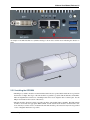
• The Pika connects to the Flight Computer via a Cat6 Ethernet cable. Use the port on the Flight Computer
closest to the sound jack, as shown below.
3
Airborne User Manual, Release 1.6
An example of the Pika installed in a cylindrical fuselage is shown below with an arrow indicating the direction of
flight.
2.2.2 Installing the GPS/IMU
• The Ellipse, by default, should be mounted with the labeled Z arrow pointed nadir and the X arrow pointed in
the direction of flight. The edges of the unit should be as parallel as possible with the airframe, and the Pika.
There are alignment holes in the base of the Ellipse that can be used to align the unit to reference pins. See the
Ellipse user manual for the location of these holes.
• The unit should be vibration isolated, if possible, but in the same inertial frame as the Pika. The GPS antenna
should be screwed into the appropriate SMA terminal, and the antenna itself should be mounted with a clear
view of the sky. Use brass screws to mount the unit. The unit should be positioned as far away from any potential
source of magnetic interference as possible.
2.2. Installing the Hardware
4
Airborne User Manual, Release 1.6
• GPS reception is sensitive to electro-magnetic interference (EMI). The GPS antenna should be placed as far
as possible away from radios, other GPS antennas, the Flight Computer, spark plugs, and any other potential
source of EMI. Try to avoid running the GPS antenna parallel to other wires or cables for much distance. A
ground plane under the antenna helps significantly. Connect GPS antenna to GPS/IMU unit.
• If using the Ellipse, connect its USB cable to any of the USB ports of the Flight Computer. If not, connect the
serial cable from the GPS/IMU to COM1 of the Flight Computer.
2.2.3 Installing the Flight Computer
• The Flight Computer needs airflow- do not completely enclose the unit or block airflow around it.
• Keep power cables to the Flight Computer as short as possible. The unit draws a substantially amount of current
at boot- long cables or wires of too small a gauge can prevent the computer from booting.
• The external USB text display is used to diagnose any errors with the system. It is optional. If used, connect to
USB port of Flight Computer.
• Mount external SSD in an accessible location. Velcro is useful for mounting, as the drive is removed from the
aircraft for data downloading. Connect the drive’s USB cable to the Flight Computer’s USB 3.0 port that is
labeled ‘Drive’. Note: It is very important NOT to plug the drive into any other USB port.
2.2.4 Installing the Downwelling Irradiance Sensor
• The optional downwelling irradiance sensor’s fiber input needs to be mounted straight-up with a clear, unobstructed view of the sky. Connect sensor to Flight Computer via USB. Do not excessively bend the optical fiber.
The NIR downwelling sensor CANNOT be placed under plexiglass/polycarbonate, as it is not transparent in that
spectral range. Ideally, the fiber head is exposed to direct light.
Once all components are installed, provide power to all components of the system (Pika, Flight Computer, and
GPS/IMU), paying close attention to min/max voltages and current requirements.
Device
Pika IIg
Pika XC
Pika NIR
Flight Comp.
MicroINS
Novatel IGM
Voltage
8-30V
5-24V
12V
9-35V
9-18V
10-30V
Power
3W
8W
60W
30W
3W
3W
2.3 Configuring the SBG Ellipse
2.3.1 Antenna Lever Arm Adjustment
The position of the antenna relative to the body of the Ellipse needs to be entered in to the sbgCenter software. Please
see the Ellipse Configuration manual for instructions on applying this offset.
The ‘Home’ position of the unit can be entered as well to speed satellite acquisition time.
Do not change any of the Input/Output or Data Output settings while using the sbgCenter.
2.3. Configuring the SBG Ellipse
5
Airborne User Manual, Release 1.6
2.3.2 Magnetometer Calibration
The magnetometer should be calibrated before data collection as well. This can be performed on the ground, or
preferably, in the air. This procedure can be performed with the sbgCenter, or if in the air, with the Resonon Ground
Station software. It has been Resonon’s experience that a 2D calibration is difficult to perform in the air due to the need
to keep the wings level. A 3D calibration is preferable for accuracy reasons and should be performed if possible. Please
see the Magnetic Calibration in Airborne Applications document for instructions on performing these calibrations.
If using the Resonon Ground Station, please see the Magnetic Calibration section in the Operation chapter of this
manual.
If using the sbgCenter sofware, please see the Magnetic Calibration in Airborne Applications document for instructions. Do not change any of the Input/Output or Data Output settings while using the sbgCenter.
2.3.3 Microhard Radio Modem
If the optional Microhard radio modems are used to communicate between the Flight Computer and the ground station
computer, a null modem connector must be used between the Flight Computer and the Microhard radio. The modem
will connect to COM2 of the Flight Computer.
2.4 Installing and Connecting to the Ground Station Software
The Resonon Ground Station Software is easily installed with the provided installer. Please uninstall older versions of
the Resonon Ground Station software before installing newer versions, then double click the installer and follow the
instructions.
2.4.1 Connecting to Ground Station
The Ground Station software communicates to the airborne system through the Microhard data link or directly through
a serial cable. These options will be discussed in more detail below.
Microhard radios
1. Make sure that the airborne radio is connected to the Comms port of the Flight Computer using a normal serial
cable and that the radio is properly powered.
2. Connect the second radio to the laptop serial port (or USB->serial adapter) using a normal serial cable. The
Resonon Ground Station software will utilize this serial port, so note the name of this port (COM1, COM2, etc).
The baud rate of this connection is 115.2 k.
3. Launch the Resonon Ground station software. The software will attempt to open the default port (COM1) at the
default baud rate (115.2 k). This will fail unless COM1 is the correct port. In the Comms menu item, set the
correct port. After the port is opened successfully, then press Check Comms to send a verification message to
the Flight Computer.
Direct connection
1. Connect the laptop serial port (or USB->serial adapter) to the Comm2 port of the Flight Computer using a
normal serial cable. The Resonon Ground Station software will utilize this serial port, so note the name of this
port (COM1, COM2, etc). The baud rate of this connection is 115.2 k.
2.4. Installing and Connecting to the Ground Station Software
6
Airborne User Manual, Release 1.6
2. Launch the Resonon Ground station software. The software will attempt to open the default port (COM1) at the
default baud rate (115.2 k). This will fail unless COM1 is the correct port. In the Comms menu item, set the
correct port. After the port is opened successfully, then press Check Comms to send a verification message to
the Flight Computer.
2.5 Installing drivers for reading Ext4 drives in Windows
The external solid state drive that the data is collected on is formatted as Ext4, which Windows does not natively
support. Therefore drivers are needed. There are a few options (Paragon, Ext2Explore), but the Ext2Fsd drivers seem
to be the best.
1. Download the driver from http://www.ext2fsd.com and install. A reboot is necessary.
2. Plug the drive into your computer and launch Ext2Fsd.
3. Find the drive labeled as Ext2. If no Volume letter has been assigned, right click on the drive entry. Select
Change Drive letter.
4. Select Add, and then Automatic Mount. Select Ok.
5. The drive should be available in Windows for normal file transfer.
2.5. Installing drivers for reading Ext4 drives in Windows
7
CHAPTER
THREE
USING THE AIRBORNE SPECTRAL IMAGING SYSTEM
3.1 Powering Up and Down
If using a laptop or external LCD to monitor the system, connect these devices to the system and then power the
system on. The laptop communication cable connects to COM2 of the Flight Computer. The external LCD connects
to a USB port of the Flight Computer.
Power up the system. The unit should remain stationary while the GPS/IMU initializes. Confirm that all systems are
operational in the Home Tab. The GPS/IMU may take a few minutes to acquire satellites and initialize.
It is preferred not to turn off power to the system without shutting it down from the Ground Station software. Shutting
down the system is covered later in this section.
3.2 Launching the Software
Launch the Resonon Ground Station. Initially, the controls will not be available. Once the imaging system is online and
communicating, the controls will be available. If you receive the message “No Response”, there is a communication
failure between the imaging system and the ground station software. It is likely that the system is still starting.
However, it may be due to a serial port setup error. Navigate to the Comms menu (described below), and try to
reconnect on the correct serial port and baud rate.
Note: If it appears that the software successfully connected to the imaging system but the controls are still not
available, select the Check Comms item in the Comms menu list.
3.3 Refresh Button
Use this button to query the Flight Computer for the most recent status and setting information. If the Flight Computer
is actively acquiring a datacube, the refresh function may take some time to return.
3.4 Home Tab
The Home tab displays useful information regarding the status of the system.
The Systems section shows the most important status components of the system, to be used as quick visual confirmation that the system is operating properly. The operator should check all fields in this section at startup. See the
Troubleshooting section for information on procedures if any of these sections are marked Fail. The downwelling
8
Airborne User Manual, Release 1.6
irradiance sensor (labeled as ‘Single Point’ in the Home tab) is optional, and the system will operate normally without
it.
The Summary section shows temperature of the flight computer and the disk space available.
3.5 Flight Tab
The Flight Tab groups functions that may be useful during flight under a single tab.
View Frame: This function will request and display the last frame of raw data. It is rarely used in normal operation.
It can provide the operator with feedback regarding the exposure settings, but is much harder to interpret than the
Histogram function.
View Last Cube: This function will request and display a highly compressed, greyscale preview of the last cube
recorded.
Note: To download a preview of the last frame and last cube, the signal strength of the Piccolo/Radio Modem
connection must be high. If the signal strength is low (low Signal To Noise ratio), the command will timeout before
the preview download can be completed.
Frame Stats: This function will request and display the minimum pixel value, maximum pixel value, and average
values for the last frame of data, intended to assist in confirming exposure settings.
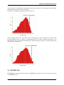
Frame Histogram: This function will request and display a histogram of the last frame of data. The histogram
feature is likely the most useful for determining if the correct exposure settings are used. Interpreting this histogram
is the same as any digital image histogram; the height of the bars show the number of pixels for each brightness level
(brightness scale: 0-4095)
Record: This button will force the system to record a datacube. It will record continuously until the Stop button
is pressed. This allows the operator to record data over an area outside of the defined target areas (discussed in the
Targets Tab section). This button is also used to record test cubes during configuration to ensure that the system can
keep up with the data bandwidth.
Stop: Stops the collection of datacubes, whether the recording was started manually or because the aircraft is inside
of a defined target region. If this function is used to stop the collection of data within a target region, collection will
begin again once the aircraft is back inside a target region.
Record Correction Cube: This button allows the collection of a Correction Cube for use with post-processing data
correction. The cube collected in this step is used to remove the instrument response as well as the illumination
function and leave the data in Absolute Reflectance (more info on post-processing can be found in Post Processing
Data with Spectronon). Before using this function, place a reflectance standard in the field of view of the imager and
in a manner such that the standard is fully illuminated by the sun (no shadows). Use AutoExposure to determine the
gain settings, and then record a correction cube. This cube will be in the flight’s root folder and named to reflect its
purpose.
Run Auto Expose: Runs the auto exposure routine.
Note: Autoexpose will not run while recording a data cube, so that while in very large target areas, drastic changes
in conditions will impact the data.
3.6 Imager Tab
This tab contains the settings relevant to the Spectral Imager.
3.5. Flight Tab
9
Airborne User Manual, Release 1.6
Shutter: This sets and displays the shutter percentage of the imager. If AutoExpose is used, it is not necessary to
manually change the shutter settings. It should also be noted that if the shutter is not set at 100% that the ground area
is effectively sub-sampled, instead of averaged. If the scene is too bright for a given frame rate and at zero gain, the
frame rate can be increased or the f/# can be increased as an alternative to altering shutter percentage. Use the Resonon
Airborne Calculator to determine how sub-sampling will affect the data.
Gain: This sets the gain of the imager. If AutoExpose is used, it is not necessary to manually change the gain settings.
It should be noted that excessively high gain settings add noise to the images.
Framerate: This sets the framerate of the system, and with it along-track spatial resolution. Use the Resonon Airborne
Calculator to determine optimum frame rate. Slower frames rates mean lower along-track spatial resolution, but better
signal to noise ratios. If the AutoExpose routine returns a “Not Enough Light” warning, the framerate may be lowered
to improve signal to noise ratios. Alternatively, the aperture of the objective lens can be increased. Please contact
Resonon regarding this procedure. If the aperture of the lens is changed, the unit must be radiometrically calibrated
again. It is possible to set the framerate faster than the flight computer can keep up with for a given number of crosstrack pixels and spectral bands. If the flight computer cannot keep up with the data flow, it will produce a warning to
the Ground Station software and quit recording. It is therefore necessary to record multiple test cubes after changing
framerates and/or resolution settings to be sure that the flight computer will properly record data. If the Ground Station
software reports “Warning: Disk can’t keep up with data rates.”, the framerate is set too high for the given spatial and
spectral resolutions. Lower one of these settings and test again. If the record command works on multiple cubes, but
the reported framerate is more than 2-3% slower than the set framerate, it it likely that the Flight Computer is dropping
frames. In this case, one of the settings should be lowered and tested again.
If you notice dropped frames in your geo-rectified data, visible by blank spots in the datacube, the framerate is set too
high for the given cross-track and band number settings.
Cross Track Pixels: This sets the cross-track spatial resolution, normally set at its maximum value. Smaller numbers
mean lower cross-track spatial resolution, but increases signal to noise ratios and produces smaller data files.
Note: The system can be configured for framerates that it cannot keep up with. Be sure to test frame rate settings
prior to flight. To do this, start a cube recording using the manual button and allow it to record for ~30 seconds. Then
stop the cube recording. In the output window, look at the message the Flight Computer has returned. In the message
is the frame rate achieved.
Bands: This sets the spectral resolution. This parameter is 80 for normal operation. Lower band numbers increases
signal to noise ratios and results in smaller file sizes, but decreases spectral resolution. Large settings in both spatial
and spectral resolution may limit the maximum FPS of the system.
Imager Orientation: This parameter sets the direction of the imager relative to the direction of flight. Set the parameter to Logo Right if the Resonon label side of the imager is facing the right (starboard) side of the plane and Logo
Left is the Resonon label is facing the left (port).
Auto Expose Settings: The Auto Expose class selection fine tunes the autoexposure routine for a variety of imaging
scenarios. “Normal” is the most versatile and serves as a starting point for most applications. “Darker areas
of Interest” is for bright backgrounds with sparse areas of darker regions of interest (glacier background with sparse,
dark pools of water of interest). “Bright Areas of Interest” is for dark backgrounds with sparse areas of bright regions
of interest (desert background with sparse, bright objects of interest). “Water” is for imaging water or other scenes
containing highly specular reflections (glare).
For custom settings, select the Custom item. The Handle and Target sliders will then become available. A description
of setting these parameters is below:
The Handle parameter determines the which percentage brightness image pixel the AutoExposure algorithm will try
to force to the Target percentage value. For instance, a Handle setting of 98% and a Target setting of 90% will try to
force the 98th percentage brightest image pixel to 90% of the maximum brightness value. This would then allow 2
percent of the image pixels to be brighter than 90% of the maximum value and be in risk of saturation, but also allow
the majority of the scene to possess good signal to noise ratios. In the case of ocean imaging where a high percentage
3.6. Imager Tab
10
Airborne User Manual, Release 1.6
of glint is probable, a smaller Handle setting might be preferred. These settings can be adjusted fine-tuned by utilizing
the Frame Histogram feature found in the Data Tab.
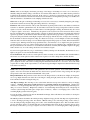
An illustration of the Handle and Target settings is shown below.
Assume a Handle setting of 98%, and a Target of 90%. The imager grabs a frame and analyzes it. It finds the 98th
percentile brightness value to be 3300 out of a maximum 4095 (12 bit resolution = 4095 DN). This is 80% of the
maximum. Thus, more gain is added and another frame is grabbed and analyzed. This process repeats until the Target
value of 90% is reached (below).
3.7 GPS/IMU Tab
The GPS/IMU tab shows the information relevant to the GPS/IMU system and serves as a check to the proper operation
of the GPS/IMU system.
3.7. GPS/IMU Tab
11
Airborne User Manual, Release 1.6
The Ground Altitude must be set for proper operation. This altitude is the Mean Sea Level (MSL) altitude of the
ground. If set incorrectly, data may not be collected in the desired Target regions.
At boot, the Flight Computer will attempt to set the system time to the GPS time reported by the GPS/IMU. If the GPS
had not acquired satellites at the time of boot, the system time will be wrong. Press the Match System Time to GPS
Time to sync the two times.
If supported by the GPS/IMU, the Get Number of Satellites button will return the number of currently fixed satellites.
The SBG Ellipse does not support this feature.
3.7.1 Magnetic Calibration
This feature calibrates the GPS/IMUs magnetometer after installation to compensate for any interference.
SBG Ellipse
To perform a calibration, first press the Calibrate Magnetometer button. Then press the Begin Calibration button. Then
fly or turn the aircraft in at least one complete circle. Then press the Compute Calibration button. If no problems were
reported, press the Apply Calibration button. If problems were reported, repeat this procedure. It may be necessary to
perform the magnetic calibration with the sbgCenter software if the proceedure cannot be completed without errors.
The magnetic calibration performed from the Resonon Ground Station is a 2D calibration, which is adequate for
conditions experienced during imaging flight paths (level). If a 3D calibration is desired, please use the sbgCenter
software.
If this procedure is done with the aircraft on the ground (in the case of UAVs, for instance), the aircraft needs to be in
level flight orientation and be away from any potential sources of magnetic interference, such as metal buildings, etc.
3.8 Computer Tab
Along with displaying the temperature of the CPU and the amount of disk space remaining, the Computer Tab also
contains functions for recovering a malfunctioning system.
Reset: Resets the embedded software. This may repair a partially crashed or unresponsive system.
Reboot: Reboots the system. This may repair a partially crashed or unresponsive system.
Shutdown: Shuts the system down. It is best (but not necessary) to shut the system down before turning off power.
3.9 Storage Tab
View Current Files: This button will show all of the data files on the solid state drive.
Offload Data: This button is only used for transferring data to a external USB drive after the aircraft has landed, and
is typically not used (instead, just shutdown the system and unplug the external SSD that contains the data).If using
this function the external drive must be formated as FAT32 (see ‘Format USB’ section in Advanced Operation for
information on formatting drives), and using a high end, high speed flash drive is encouraged.
To use, plug in the external drive and power it on. Wait 10-15 seconds for the Flight Computer to recognize the drive.
Then press this button. When the files have been transferred, a message will appear in the output window showing the
files that have been successfully transferred. Depending on the amount of data collected, this may take some time.
Check Disk: This function will perform a system check and disk maintenance. It should be performed periodically,
after a power loss while recording data, or if the system is reported errors. It may also be prudent to perform after
completed flights to prevent problems arising for the next flight.
3.8. Computer Tab
12
Airborne User Manual, Release 1.6
Clear Data Disk: Deletes all of the spectral imaging data on the system. Do not delete data until you have offloaded
it to your computer!
3.10 Targets Tab
The Target tab allows to create, save, and upload target regions to the flight computer. These Target regions define the
areas for which the system will record data over.
For KML target areas:
Target KML files are created in Google Earth. First, use the Add -> Folder option in Google Earth to create a folder.
Next create one of more polygon areas with the Add Polygon tool. These polygons should be inside of the newly
created folder and both the folder and polygons should have meaningful names. Last, right click on the folder and
select Save Place As. Use the drop down option to select KML as the format (KMZ is not supported) and save to an
appropriate location.
Upload the KML target file using the Upload button. An error message will warn the user if the KML does not contain
valid polygons.
For Legacy target areas:
To create a target, navigate to the Targets menu, and select New Target. Each field of the new target (Name, Lat., Long.,
etc) are editable by clicking in the field. Enter in the name, Latitude and Longitude in Decimal Degrees, a minimum
AGL altitude, and a diameter. The system will collect data anytime it is in the circle defined by these parameters. The
minimum altitude setting prevents the system from recording data while it is on the ground of the launch/landing zone,
if the launch/landing area is within a Target region. Once a target file has been created, it can be saved locally for use
later.
Once a target file has been created or loaded from a locally saved file, it needs to be uploaded to the Flight Computer.
This is accomplished through the Targets menu item Upload Local Targets. After the Refresh Now button is pressed,
the Remote Target List should match the Local Target List.
A target list can be saved locally through the Targets menu item Save Target File or Save Target File As items.
To clear Remote targets, create a blank local target list and upload.
When data is recorded in a target region, the name of the target region is reflected in the data folder name.
3.11 Command Line
The Command Line tab contains an output window of all messages from the Flight Computer, as well as an input
window for sending messages up. Please see Advanced Operation for a description.
3.12 Menu Items
3.12.1 Preferences
Check Location Interval: This parameter is the rate at which the system checks its position to determine if the unit
is within a Target area. An interval of 1 second is recommended for all applications.
Status Refresh Interval: This sets the Refresh rate of the Ground Station Software, which is enabled by checking the
Auto Refresh checkbox in the Status tab.
3.10. Targets Tab
13
Airborne User Manual, Release 1.6
Auto Exposure Interval: Settings are normally saved on shutdown. However, pressing this button will save settings
immediately.
View Output In Separate Window: Shows all up/down messages in a separate floating window for easy viewing.
3.12.2 Comms
Connect: This button is used to try to reconnect to the serial port if the wrong port was specified in the batch file.
Check Comms: This button checks the communication between the Ground Station software and the Flight Computer.
Baud Rate: Sets the baud rate of the connection. Use 9600 for direct connection to the Payload port of the ground
station, 57600 for use with the Payload Decoder.
Comm Port: Sets the communication port.
3.12.3 Targets
If using KML targets, there are not menu item options. If using Legacy targets, the following commands are utilized.
New Target File: Creates a new, blank local target file
Open Target File: Opens an existing local target file
Save Target File: Saves a target file locally
Save Target File As: Saves a target file locally
New Local Target: Creates a new target in the current local target file
Clear Local Targets: Clears the current target fields
Upload Local Targets: Uploads the current local target file to the Flight Computer
Download Local Targets: Downloads the target file in the Flight Computer to the local file
3.13 Transferring Data
The fastest way to transfer data is to:
1. Shut down the Flight Computer
2. Unplug the SSD drive.
3. Plug the SATA drive into computer.
4. Use ‘Ext4Fsd’ to read the drive and copy data. See the secction Installing drivers for reading Ext4 drives in
Windows for more information.
It is also possible to plug the Flight Computer into a DHCP network and transfer the data via Ethernet, either through
Windows Network sharing service or with a SCP client. See Advanced Operation for instructions on putting the Flight
Computer on a network.
The last alternative is to plug in an external USB drive, formatted as FAT32, to a USB port of the flight computer and
press the Offload Data button in the Storage Tab.
3.13. Transferring Data
14
Airborne User Manual, Release 1.6
3.14 Using GeoReg
1. Launch GeoReg
2. Select file or folder of files to geo-correct
3. Go to Settings. Select desired output data products.
4. Enter in the instruments FOV and any known angular biases.
5. There is a small time offset usually needed in the Interpolation field, usually between -.01 and -.02. This offset
can be determined by looking at higher frequency roll effects and determining if the GPS/IMU data is ahead or
behind the image data. (If adjusting this value, the .txt file in the data folder must be deleted between runs).
6. If units of radiance are required, select the radiance calibration file supplied with the imager in the Calibration
field.
7. GeoReg is installed with a world DEM, which can be used, as well as a flat earth model or a user supplied DEM.
8. In the ENVI/Images tab, select the desired resolution and RGB bands.
9. In the main screen, select Process Files.
The table below lists the FOV of the Pika II with different objective lenses. This information is necessary for
the georectification software. It is not exact and may have to be adjusted for your particular imager.
Focal Length(mm)
Pika II FOV(deg)
Pika II IFOV(mrad)
70
3.9
0.2
50
5.5
0.3
Focal Length(mm)
Pika XC FOV(deg)
Pika XC IFOV(mrad)
70
7.2
0.36
50
10.0
0.5
Focal Length(mm)
Pika NIR FOV(deg)
Pika NIR IFOV(mrad)
75
7.3
0.4
50
11
0.6
3.14. Using GeoReg
23
12.00
0.65
23
21.5
1.1
17
16.00
0.88
12
22.50
1.25
17
29.0
1.5
12
40.0
2.1
8
33.00
1.88
8
57.5
3.1
6
43.5
2.5
6
72.0
4.2
25
22
1.2
15
CHAPTER
FOUR
OPERATION SUMMARY AND CHECKLIST
4.1 Mission Setup
1. Upload the Target KML.
2. Set Framerate, Cross Track Pixels, and Bands settings. Record test cubes to ensure the flight computer can
handle the data rate. If not, decrease frame rate, number of bands, or number of cross-track pixels.
3. Set AutoExposure Class and Interval.
4. Set Location Check Interval.
5. Perform Check Disk function for routine maintenance
4.2 Pre Flight
Normal pre-flight operations are summarized below. Please see the preceding section for more details on these operations.
1. Power up system. Ideally, the system should be still during power up and remain still until GPS/IMU has been
initialized.
2. Launch Ground Station software.
3. Verify all systems are operational.
4. Delete existing data.
5. Match system time to GPS time, if necessary.
6. Set Ground Level altitude if using target area Minimum Altitude Setting 6. Optionally, AutoExpose on White
Reference and Collect Correction Cube.
4.3 Flight (All operations are optional)
1. Perform magnetic calibration, if necessary. This only needs to be done once as long as the plane and installation
do not change.
2. Perform AutoExposure, if necessary.
3. Confirm Collection of Datacubes while in Target Areas.
4. Check Histogram, confirm Exposure settings are correct.
5. Optionally, shut down system (via Shutdown button) for return flight.
16
Airborne User Manual, Release 1.6
4.4 Post Flight
1. Shut down Flight Computer
2. Remove data drive and offload data using dock/cable.
3. Convert data to radiance or absolute reflectance
4. Geo-rectify Data with Geo-Reg or Parge.
Please see the Spectronon User manual for information on correcting data for the instrument function and absolution
reflectance.
4.5 Data Files and Structure
The top level data folder is named by date. Inside of the data folder are folders named by target polygon name and
number. Inside of these folders are the .bip, .hdr, .lcf, and.times files. A description of all data files follows.
Per Image Files:
*.bil - The hyperspectral raw image data
*.hdr - The header file for the bip
*.times - Lists the timestamps for each frame in the HSI file. In future versions, This data may be included in the
*.bip.hdr file under the var name “line time stamps”
*.lcf - Contains the actual location data pulled from the GPS/IMU during the cube recording. The first column contains
the time stamps. If you select to save the debug files, this data can be re-saved as a raw format datacube with one layer
for each location data type. This file will be of type “ins” with a corresponding “ins.hdr”
Georectification Result Files:
*.igm - The IGM file is a data cube of the same dimensions as the original BIP file, but with only 2 bands. The data
in those bands is the Latitude and Longitude for each image pixel. This is used to create the GLT file. Once a GLT is
made, this file can be deleted, but if you are trying different Grid Density Multiplier values, having this file will speed
up that process.
*.igm.hdr - IGM header file.
*.XV The XV file is a georectified spectral image data cube which can be opened directly with ENVI.
*.xv.hdr XV header file
*.kml - Georectified version of the current rendering (True Color, NVDI, SAM, etc) for use in Google Earth or similar
programs.
*.png - Image used in the KML file
4.6 Keys to Obtaining Quality Data
• Collect data under cloudless skies or uniformly cloudy conditions between 10 am and 2 pm.
• The largest spatial and spectral binning necessary for the application
• If the system is operating at non-zero gain, signal to noise ratios can be improved by slowing done the frame
rate to the slowest rate necessary for the application
4.4. Post Flight
17
Airborne User Manual, Release 1.6
• A high quality Correction Cube will improve data fidelity (if using). Make sure there are no shadows or glare
present when recording this cube.
• The GPS/IMU’s attitude solution is less accurate after turns. When creating a flight plan, allow the aircraft
to travel straight for a short time before entering areas to be recorded. This increases the accuracy of the
georectification.
• If AutoExposure returns a “Not Enough Light” warning, the framerate can be turned down (smaller FPS setting).
This will increase the integration time of the system, allowing more light to enter. Decreasing the framerate will
decrease the along-track spatial resolution: if this is not desirable, the system can still be flown after a “Not
Enough Light” warning, but the images may be dark and/or noisy. Alternatively, the aperture of the Pika’s
objective lens can be adjusted. Please contact Resonon for consultation on this procedure.
4.7 Post Processing Data with Spectronon
Spectronon, Resonon’s free spectral image analysis software, can be used to process airborne data from arbitrary units
to Radiance or Reflectivity. There are a variety of Spectronon plugins available for each conversion.
The Airborne Radiance Conversion and Airborne Reflectance Conversion are the preferred methods for radiance and
reflectivity conversion (via downwelling data) as these methods are more accurate for the Pika XC and Pika NIR
imagers. These methods use ‘Radiometric Calibration Pack’ files with a .zip extension.
The other plugins available are the Radiance and Reflectivity Conversion (not airborne specific) plugins. These plugins
use the ‘GeoReg Radiometic Calibration’ file.
Airborne Radiance:
1. With Spectronon, open the airborne datacube to convert.
2. Right click on the datacube to convert in the Resource Tree in the right hand side of the main Spectronon
window. Select New Cube -> Correct -> Airborne Radiance Conversion.
3. In the resulting window, select the name of the radiometric calibration pack, then press OK. The resulting cube
will be in units of microflicks (1 microwatt per steradian per square centimeter of surface per micrometer of
span in wavelength).
Radiance:
1. With Spectronon, open the radiometric calibration datacube, as supplied by Resonon for your spectral imager.
2. Open the airborne datacube to convert.
3. Right click on the datacube to convert in the Resource Tree in the right hand side of the main Spectronon
window. Select New Cube -> Correct -> Radiance Conversion.
4. In the resulting window, select the name of the radiance calibration cube, then press OK. Optionally, supply a
dark current cube. If no dark current cube is supplied, the dark current cube collecting during calibration will
be used. The resulting cube will be in units of microflicks (1 microwatt per steradian per square centimeter of
surface per micrometer of span in wavelength).
Airborne Reflectance (via Downwelling Data):
Data can be converted to reflectivity using the optional Downwelling Irradiance sensor via the following steps.
1. Open the airborne datacube to convert.
2. Open the downwelling irradiance spectrum that is in the same folder as the airborne datacube.
3. Right click on the datacube to convert in the Resource Tree in the right hand side of the main Spectronon
window. Select New Cube -> Correct -> Airborne Reflectance Conversion.
4.7. Post Processing Data with Spectronon
18
Airborne User Manual, Release 1.6
4. In the resulting window, select the name of the radiance calibration pack for the imager, and the downwelling
irradiance sensor’s radiance calibration pack. Press OK. The resulting cube will be in Reflectivity on a scale of
0 to 1 (unitless).
Reflectance (via Downwelling Data):
Data can be converted to reflectivity using the optional Downwelling Irradiance sensor via the following steps.
1. With Spectronon, open the radiometric calibration datacube, as supplied by Resonon for your spectral imager.
2. Open the airborne datacube to convert.
3. Open the radiometric calibration spectrum for the downwelling irradiance sensor, as supplied by Resonon.
4. Open the downwelling irradiance spectrum that is in the same folder as the airborne datacube.
5. Right click on the datacube to convert in the Resource Tree in the right hand side of the main Spectronon
window. Select New Cube -> Correct -> Reflectance Conversion.
6. In the resulting window, select the name of the radiance calibration cube for the imager, the downwelling
irradiance spectrum, and the downwelling irradiance calibration spectrum. Optionally, supply a dark current
cube. If no dark current cube is supplied, the dark current cube collecting during calibration will be adjusted for
shutter differences and used. Press OK. The resulting cube will be in Reflectivity on a scale of 0 to 1 (unitless).
Reflectance via In Scene Reference Spectrum:
If there is an object in the scene of known (measured) reflectivity, it can be used to convert the data to reflectivity via
the following steps.
1. Convert data to units of radiance.
2. Select ROI of object of known reflectivity and create a Mean Spectrum.
3. Select New Cube -> Correct -> Correct From Spectrum.
4. Press the Measured Reflectivity button and select the file containing the reflectivity measurements. This file
should be a tab or space delimited, with wavelength units in nanometers.
5. If the reflectivity of the reference is spectrally flat over the wavelength range of interest, you do not need to use
a Measured Reflectivity file. Instead, use the Scale slider to select the reflectivity of the reference.
Export to KML: Spectronon supports exported processed spectral image cubes to KML format data.
1. Open a .xv file, as generated by GeoReg.
2. Process the data using the normal analysis tools of Spectronon.
3. Select the resultant Image and use Export Image as KML. Note: In order for the background pixels (the buffer
areas around the spectral image data used to make the image square) transparent in the KML, they must be
black in the Image. You may have to use various filters (Invert, Strech,Threshold, etc) in order to make the
buffer pixels black before exporting to KML.
Batch Scripts: Spectronon supports batch scripts for processing entire folders of datacubes. This can be very useful
for simplifying the processing pipeline. Batch scripts can be used to convert data to radiance or reflectance, or analyze
the data. Airborne-specific batch files can copy LFC and TIMES files necessary for geo-correction to the same path
as the resulting processed files.
4.7. Post Processing Data with Spectronon
19
Airborne User Manual, Release 1.6
4.8 Post Processing Data with GeoReg
4.8. Post Processing Data with GeoReg
20
CHAPTER
FIVE
ADVANCED OPERATION
5.1 Sending Special Commands to the Flight Computer
Many of the following sections require sending special commands to the flight computer. This is done through the
ground station software via serial cable. With the system running, navigate to the Command Line tab. Click in the
command-line box at the bottom of the window and type your command. Press <enter> to send the command to the
flight computer. For example:
getVersion()
The command and any response from the flight computer command interpreter appear in the Raw Output section
above:
>>> getVersion()
<<< Revision: 1.0
5.2 Connecting the Flight Computer to a Network
The flight computer comes with 2 Gigabit Ethernet ports. The port nearest the sound jack is reserved for the Pika IIg
imager. The second port can be used to connect to a network and the Internet.
Connect the flight computer’s second ethernet cable (eth0 or gigabit 0) to a DHCP enabled Internet connection.
If the network connection fails, make sure the correct ethernet cable is connected to your DHCP enabled network and
try again. If it still doesn’t work, the connection can be brought up manually, as described below:
In the ground station command line, use the eth1up() command:
>>> eth1up()
<<< Bringing up secondary ethernet interface.
<<< Success. IP address is 192.168.0.181
Please wait...
If the flight computer successfully obtains an IP address from your network, it is returned. If no IP address could be
acquired the connection fails:
>>>
<<<
<<<
<<<
eth1up()
Bringing up secondary ethernet interface. Please wait...
Failed to contact DHCP server. Bringing interface down...
Failed to bring up eth1 interface
Note: The flight computer waits for a DHCP server to assign it an IP address. As a result, it can take some time to
get the results of this call, especially if a DCHP server is not found. Please be patient.
21
Airborne User Manual, Release 1.6
5.3 Updating Firmware
The firmware of the spectral imaging system can be updated via the Internet. This update should only be done under
the request and guidance of Resonon personnel.
1. Create an account at downloads.resonon.com.
2. Resonon personel must enable your account enabled to view and download airborne software. Please provide
your account username when you contact us.
3. Connect the flight computer to the Internet. See Connecting the Flight Computer to a Network.
4. Use checkForUpdates() to see the most recent software version.
>>> checkForUpdates()
<<< You are running version 1.0.
The most recent version is 1.0.
5. On the advice of Resonon staff, use upgradeSystem(‘username’, ‘password’) to upgrade the airborne flight
computer. Replace username and password with the username and password you created in step 1.
>>>
<<<
<<<
<<<
<<<
<<<
<<<
<<<
upgradeSystem('username','password')
Upgrading to version 1.0. Please wait...
Downloading airborne...
Installing airborne...
Upgrade finished. Restarting...
exited
comm.pref found. starting...
Starting Airborne. Revision: 1.0
...
...
The system installs the new software and restarts automatically.
Note: If you account at downloads.resonon.com has not been enabled by Resonon staff for airborne downloads,
this step will fail. Contact Resonon for support.
5.4 Pairing a Pika II with a Flight Computer
In order to use a different Pika II than the original with the Flight Computer (or after a disk reformat), the calibration
numbers from the Pika II must be entered into the Flight Computer. This is done though the Command window in the
Command Line tab.
To enter in a slope (in this case, a value of 1.08), do:
setSlope(1.08)
followed by the Enter key.
To set the intercepts (in this case, 400.12), enter:
setIntercept(400.12)
followed by the Enter key.
5.3. Updating Firmware
22
Airborne User Manual, Release 1.6
5.5 Pairing a GPS/IMU with a Flight Computer
To change which type of GPS/IMU the Flight Computer is paired with, enter one of the following commands:
setImu('Ellipse')
setImu('Athena')
setImu('Novatel')
setImu('Piccolo')
5.6 Pairing/Unpairing a Downwelling Irradiance sensor with a Flight
Computer
If a downwelling irradiance sensor is not being used, the system will boot faster if the Flight Computer is instructed
not to attempt to connect. To do this, go to the Command window and enter:
preferences.setitem('singlepoint',False)
If you need to instruct the Flight Computer to attempt to connect to a downwelling sensor, use the following:
preferences.setitem('singlepoint',True)
5.7 Reformatting Disks or Adding Additional Disks
For system errors that the Check Disk function does not fix, it may be necessary to reformat the disks. This should
only be performed after consultation with Resonon personnel. Reformatting the disk will erase all data, settings, and
targets, as well as the Pika II calibration and GPS/IMU type.
To reformat the disks, enter the following line into the Command window:
reformatDisk()
followed by the Enter key. The reformatting process can take many minutes and the system will appear unresponsive
during that time. Do not shut off the system. After a reformat all settings will be returned to default. The slope and
intercept of the Pika must be entered again (see Pairing a Pika II with a Flight Computer). Also, all target areas will
be deleted. Additionally, the GPS/IMU setting will default back to “Athena”. Please see Pairing a GPS/IMU with a
Flight Computer for pairing the GPS/IMU with the Flight Computer.
To format the USB thumb drive, insert the USB drive and allow a few seconds for it to be recognized. Then use:
formatUSB()
This will delete all data on the USB drive.
reformatDisk() can also be used to format an additional SSD SATA data disk. Please consult Resonon for disk drive
model recommendations. All preferences, including slope and intercept, will be deleted and will have to be entered
again.
Warning: The choice of SSD disk is important to system performance. In particular, the drive must support the
TRIM command. Data loss can occur if it does not!
5.5. Pairing a GPS/IMU with a Flight Computer
23
Airborne User Manual, Release 1.6
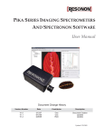
5.8 Uploading Error Logs
If the system is experiencing problems, Resonon personnel may request a system error log to assist in correcting the
problem. To do this, connect the Flight Computer to a DHCP enabled internet connection (see Connecting the Flight
Computer to a Network). Then type uploadErrorLog() followed by a Enter.
5.9 Changing Default Cube Length
By default, the airborne system breaks datacubes into ~2000 lines. When a cube nears 2000 lines, it is written to disk
and a new cube is instantiated. This results in a small area of missing data (called a data holiday). For small target
areas, this holiday may be avoided by increasing the size of the default cube length. This value can be changed by
typing setCubeSize(size) into the Command field.
5.10 Troubleshooting
System Checks
• Imager Fail: Cannot find spectral imaging unit. Reset. Reboot. Check cabling.
• IMU Fail: Cannot find GPS/IMU. Check port settings and cabling. Confirm proper GPS/IMU firmware and
configuration.
• Storage: Verify the SSD disk is connected and restart. Perform Check Disk. If Check Disk does not solve the
problem, follow the above directions to Reformat the disk. A reformat will reset all settings to default.
• Single Point Fail: Shutdown the Flight Computer and unplug power. Check cabling. Wait 10-15 seconds and
power back up.
Data problems:
• Saturated Data: Use the Custom Autoexposure class and turn down the Handle setting from the current value.
• Dark Data: Use the Custom Autoexposure class and turn up the Handle setting from the current value.
• Noisy Data: Lower the Framerate setting. This will decrease along-track spatial resolution. Alternatively, the
aperture of the objective lens may be increased. Please contact Resonon regarding before adjusting the aperture.
• GPS Latitude and Longitude are incorrect: Reposition GPS antenna away from any potential sources of
EMI.
• Poor Geo-rectification performance: Have aircraft fly straight and level before entering target area, which
allows the GPS/IMU to settle. Also, check GPS reception and reposition antenna if necessary.
• Dropped Frames: Dropped frames look like missing lines of data in the geo-rectified data. If your data exhibits
dropped frames, the framerate is set too high for the cross-track and band number settings.
5.8. Uploading Error Logs
24