1
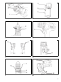
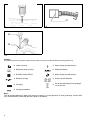
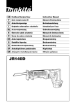
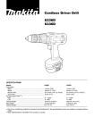
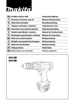
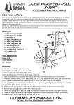
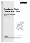
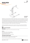
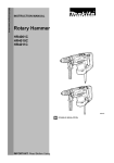
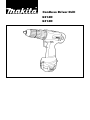
Cordless Driver Drill
6214D
6314D
SPECIFICATIONS
Model
6214D
Capacities
Steel ................................................................................................ 10 mm
Wood ............................................................................................... 21 mm
Wood screw ..................................................................................... 6.4 mm x 55 mm
Tool screw ........................................................................................ 6 mm
No load speed (min-1)
High ................................................................................................. 0 – 1,100
Low .................................................................................................. 0 – 350
Overall length ..................................................................................... 197 mm
Net weight .......................................................................................... 1.7 kg
Rated voltage ..................................................................................... D.C. 12 V
6314D
13 mm
24 mm
6.4 mm x 55 mm
6 mm
0 – 1,100
0 – 350
208 mm
1.7 kg
D.C.12 V
• Due to our continuing programme of research and development, the specifications herein are subject to
change without notice.
• Note: Specifications may differ from country to country.
For European countries only
Noise and Vibration
The typical A-weighted sound pressure level is not
more than 71 dB (A).
The noise level under working may exceed 85 dB (A).
– Wear ear protection. –
The typical weighted root mean square acceleration
value is not more than 2.5 m/s2
EC-DECLARATION OF CONFORMITY
The undersigned, Yasuhiko Kanzaki, authorized by
Makita Corporation, 3-11-8 Sumiyoshi-Cho, Anjo,
Aichi 446-8502 Japan declares that this product
(Serial No. : series production)
manufactured by Makita Corporation in Japan is in
compliance with the following standards or standardized documents,
EN50260, EN55014
in accordance with Council Directives, 89/336/EEC
and 98/37/EC.
Yasuhiko Kanzaki
CE 98
EC-DECLARATION OF CONFORMITY
The undersigned, Yasuhiko Kanzaki, authorized by
Kao Lung Tamura Electronics Co., Ltd. No. 4 Industry
1st Street, Ping Tung Industry District Chiao Nan Li,
Ping Tung City, Taiwan declares that this battery
charger
(Serial No. : series production)
manufactured by Kao Lung Tamura Electronics Co.,
Ltd. in Taiwan is in compliance with the following
standards or standardized documents,
EN60335, EN55014, EN61000
in accordance with Council Directives, 73/23/EEC
and 89/336/EEC.
Yasuhiko Kanzaki
CE 94
Director
MAKITA INTERNATIONAL EUROPE LTD.
Michigan Drive, Tongwell, Milton Keynes,
Bucks MK15 8JD, ENGLAND
Director
MAKITA INTERNATIONAL EUROPE LTD.
Michigan Drive, Tongwell, Milton Keynes,
Bucks MK15 8JD, ENGLAND
2
1
2
3
4
2
1
2
6
5
7
8
3
4
9
9
10
14
15
11
12
16
13
5
6
21
17
18
19
20
7
22
8
3
23
9
10
24
25
11
Symbols
The following show the symbols used for the tool. Be sure that you understand their meaning before use.
❏ Indoor use only
❏ Delay charge (too hot battery)
❏ Read instruction manual.
❏ Deffective battery
❏ DOUBLE INSULATION
❏ Delay charge (too hot battery)
❏ Ready to charge
❏ Always recycle batteries.
❏ Charging
❏
Do not discard batteries into garbage
can or the like.
❏ Charging complete
Note:
The recycling method may differ from country to country, or state (province) to state (province). Consult with
your nearest Makita Authorized Service Center or Distributor.
4
ENGLISH
Explanation of general view
1
2
3
4
5
6
7
8
9
Button
Battery cartridge
Charging light
Fast charger
Tighten
Sleeve
Ring
Switch trigger
Reversing switch lever
10
11
12
13
14
15
16
17
18
A side
B side
Clockwise
Counterclockwise
Low speed
High speed
Speed change lever
Adjusting ring
Graduations
SAFETY INSTRUCTIONS
WARNING! When using battery operated tools basic
safety precautions, including the following, should be
followed to reduce the risk of fire, leaking batteries
and personal injury: Read these instructions before
operating this product and save these instructions.
For safe operation:
1. Keep work area clean
– Cluttered areas and benches invite injuries.
2. Consider the work environment.
– Do not expose the tool to rain. Keep work area well
lit. Do not use tools in the presence of flammable
liquids or gases.
3. Keep children away
– Do not let visitors touch the tool. Keep visitors
away from work area.
4. Store batteries or idle tools
– When not in use, tools and batteries should be
stored separately in a dry, high or locked up place,
out of reach of children.
– Ensure that battery terminals cannot be shorted by
other metal parts such as screws, nails, etc.
5. Do not force the tool
– It will do the job better and safer at the rate for
which it was intended.
6. Use the right tool
– Do not force small tools or attachments to do the
job of a heavy duty tools. Do not use tools for purposes not intended.
7. Dress properly
– Do not wear loose clothing or jewellery, they can
be caught in moving parts. Non-skid footwear is
recommended when working outdoors. Wear protecting hair covering to contain long hair.
8. Use protective equipment
– Use safety glasses and if the cutting operation is
dusty, a face or dust mask.
9. Connect dust extraction equipment
– If devices are provided for the connection of dust
extraction and collection ensure these are connected and properly used.
10. Do not abuse the supply cord (if fitted)
– Never carry the tool by the cord or yank it to disconnect from the socket. Keep the cord away from
heat, oil and sharp edges.
11. Secure the work
– Use clamps or a vice to hold the work. It is safer
than using your hand and it frees both hands to
operate the tool.
12. Do not over-reach
– Keep proper footing and balance at all times.
19
20
21
22
23
24
25
Drill marking
Pointer
Screw
Set plate
Limit mark
Screwdriver
Brush holder cap
13. Maintain tools with care
– Keep cutting tools sharp and clean for better and
safer performance. Follow instructions for lubrication and changing accessories. Inspect tool cords
periodically and if damaged have repaired by an
authorized service facility.
14. Disconnect tools
– Where the design permits, disconnect the tool
from its battery pack when not in use, before servicing and when changing accessories such as
blades, bits and cutters.
15. Remove adjusting keys and wrenches
– Form the habit of checking to see that keys and
adjusting wrenches are removed from the tool
before turning it on.
16. Avoid unintentional starting
– Do not carry the tool with a finger on the switch.
17. Stay alert
– Watch what you are doing. Use common sense.
Do not operate the tool when you are tired.
18. Check damaged parts
– Before further use of the tool, a guard or other part
that is damaged should be carefully checked to
determine that it will operate properly and perform
its intended function. Check for alignment of moving parts, free running of moving parts, breakage
of parts, mounting and any other condition that
may affect its operation. A guard or other part that
is damaged should be properly repaired or
replaced by an authorized service facility unless
otherwise indicated in this instruction manual.
Have defective switches replaced by an authorized
service facility. Do not use the tool if the switch
does not turn it on and off.
19. Warning
– The use of any accessory or attachment, other
than recommended in this instruction manual, may
present a risk of personal injury.
– Ensure that the battery pack is correct for the tool.
– Ensure that the outside surface of battery pack or
tool is clean and dry before plugging into charger.
– Ensure that batteries are charged using the correct charger recommended by the manufacturer.
Incorrect use may result in a risk of electric shock,
overheating or leakage of corrosive liquid from the
battery.
20. Have your tool repaired by a qualified person
– This tool is constructed in accordance with the relevant safety requirements. Repairs should only be
carried out by qualified persons using original
spare parts, otherwise this may result in considerable danger to the user.
5
21. Disposal of battery
– Ensure battery is disposed of safety as instructed
by the manufacturer.
4.
5.
IMPORTANT SAFETY INSTRUCTIONS FOR
CHARGER & BATTERY CARTRIDGE
ENC001-3
1.
2.
3.
4.
5.
6.
7.
8.
9.
10.
11.
12.
13.
14.
15.
SAVE THESE INSTRUCTIONS — This manual
contains important safety and operating instructions for battery charger.
Before using battery charger, read all instructions and cautionary markings on (1) battery
charger, (2) battery, and (3) product using battery.
CAUTION — To reduce risk of injury, charge only
MAKITA type rechargeable batteries. Other types
of batteries may burst causing personal injury
and damage.
Do not expose charger to rain or snow.
Use of an attachment not recommended or sold
by the battery charger manufacturer may result
in a risk of fire, electric shock, or injury to persons.
To reduce risk of damage to electric plug and
cord, pull by plug rather than cord when disconnecting charger.
Make sure cord is located so that it will not be
stepped on, tripped over, or otherwise subjected
to damage or stress.
Do not operate charger with damaged cord or
plug — replace them immediately.
Do not operate charger if it has received a sharp
blow, been dropped, or otherwise damaged in
any way; take it to a qualified serviceman.
Do not disassemble charger or battery cartridge;
take it to a qualified serviceman when service or
repair is required. Incorrect reassembly may
result in a risk of electric shock or fire.
To reduce risk of electric shock, unplug charger
from outlet before attempting any maintenance
or cleaning. Turning off controls will not reduce
this risk.
The battery charger is not intended for use by
young children or infirm persons without supervision.
Young children should be supervised to ensure
that they do not play with the battery charger.
If operating time has become excessively
shorter, stop operating immediately. It may
result in a risk of overheating, possible burns
and even an explosion.
If electrolyte gets into your eyes, rinse them out
with clear water and seek medical attention right
away. It may result in loss of your eyesight.
ADDITIONAL SAFETY RULES FOR
CHARGER & BATTERY CARTRIDGE
1.
2.
3.
6
Do not charge Battery Cartridge when temperature is BELOW 10°C (50°F) or ABOVE 40°C
(104°F).
Do not attempt to use a step-up transformer, an
engine generator or DC power receptacle.
Do not allow anything to cover or clog the
charger vents.
6.
7.
8.
9.
Always cover the battery terminals with the battery cover when the battery cartridge is not
used.
Do not short the battery cartridge:
(1) Do not touch the terminals with any conductive material.
(2) Avoid storing battery cartridge in a container
with other metal objects such as nails, coins,
etc.
(3) Do not expose battery cartridge to water or
rain.
A battery short can cause a large current flow,
overheating, possible burns and even a breakdown.
Do not store the tool and battery cartridge in
locations where the temperature may reach or
exceed 50°C (122°F).
Do not incinerate the battery cartridge even if it
is severely damaged or is completely worn out.
The battery cartridge can explode in a fire.
Be careful not to drop, shake or strike battery.
Do not charge inside a box or container of any
kind. The battery must be placed in a well ventilated area during charging.
ADDITIONAL SAFETY RULES FOR TOOL
ENB022-1
1.
2.
3.
4.
5.
6.
7.
8.
Be aware that this tool is always in an operating
condition, because it does not have to be
plugged into an electrical outlet.
Hold tool by insulated gripping surfaces when
performing an operation where the cutting tool
may contact hidden wiring. Contact with a “live”
wire will also make exposed metal parts of the
tool “live” and shock the operator.
Always be sure you have a firm footing.
Be sure no one is below when using the tool in
high locations.
Hole the tool firmly.
Keep hands away from rotating parts.
Do not leave the tool running. Operate the tool
only when hand-held.
Do not touch the drill bit or the workpiece immediately after operation; they may be extremely
hot and could burn your skin.
SAVE THESE INSTRUCTIONS.
OPERATING INSTRUCTIONS
Installing or removing battery cartridge (Fig. 1)
• Always switch off the tool before insertion or removal of
the battery cartridge.
• To remove the battery cartridge, withdraw it from the
tool while pressing the buttons on both sides of the cartridge.
• To insert the battery cartridge, align the tongue on the
battery cartridge with the groove in the housing and slip
it into place. Always insert it all the way until it locks in
place with a little click. If not, it may accidentally fall out
of the tool, causing injury to you or someone around
you.
• Do not use force when inserting the battery cartridge. If
the cartridge does not slide in easily, it is not being
inserted correctly.
Charging (Fig. 2)
Plug the fast charger into the proper AC voltage source. The charging light will flash in green color. Insert the battery
cartridge so that the plus and minus terminals on the battery cartridge are on the same sides as their respective markings on the fast charger. Insert the cartridge fully into the port so that it rests on the charger port floor. When the battery cartridge is inserted, the charging light color will change from green to red and charging will begin. The charging
light will remain lit steadily during charging. When the charging light color changes from red to green, the charging
cycle is complete. Refer to the table below for the charging time. If you leave the battery cartridge in the charger after
the charging cycle is complete, the charger will switch into its “trickle charge (maintenance charge)” mode which will
last approximately 24 hours. After charging, unplug the charger from the power source.
Battery type
Capacity (mAh)
Number of cells
Charging time
1200
1,300
10
Approx. 30 min.
1202, 1202A, 1222
2,000
10
Approx. 45 min.
1233
2,200
10
Approx. 50 min.
1234
2,600
10
Approx. 60 min.
1235
3,000
10
Approx. 70 min.
CAUTION:
• The fast charger is for charging Makita battery cartridge. Never use it for other purposes or for other manufacturer’s
batteries.
• When you charge a new battery cartridge or a battery cartridge which has not been used for a long period of time, it
may not accept a full charge. This is a normal condition and does not indicate a problem. You can recharge the battery cartridge fully after discharging it completely and recharging a couple of times.
• If you charge a battery cartridge from a just-operated tool or a battery cartridge which has been left in a location
exposed to direct sunlight or heat for a long time, the charging light may flash in red color. If this occurs, wait for a
while. Charging will begin after the battery cartridge cools. The battery cartridge will cool faster if you remove the
battery cartridge from the fast charger.
• If the charging light flashes alternately in green and red color, a problem exists and charging is not possible. The terminals on the charger or battery cartridge are clogged with dust or the battery cartridge is worn out or damaged.
• If you wish to charge two battery cartridges, allow 15 minutes between chargings on the fast charger.
Trickle charge (Maintenance charge)
If you leave the battery cartridge in the charger to prevent spontaneous discharging after full charge, the charger will
switch into its “trickle charge (maintenance charge)” mode and keep the battery cartridge fresh and fully charged.
Tips for maintaining maximum battery life
1.
2.
3.
4.
Charge the battery cartridge before completely discharged. Always stop tool operation and charge the battery
cartridge when you notice less tool power.
Never recharge a fully charged battery cartridge. Overcharging shortens the battery service life.
Charge the battery cartridge with room temperature at 10°C – 40°C (50°F – 104°F). Let a hot battery cartridge
cool down before charging it.
Charge the Nickel Metal Hydride battery cartridge when you do not use it for more than six months.
Installing or removing driver bit or drill bit (Fig. 3)
Reversing switch action (Fig. 5)
Important:
Always be sure that the tool is switched off and the battery cartridge is removed before installing or removing
the bit.
CAUTION:
• Always check the direction of rotation before operation.
• Use the reversing switch only after the tool comes to a
complete stop. Changing the direction of rotation
before the tool stops may damage the tool.
• When not operating the tool, always set the reversing
switch lever to the neutral position.
Hold the ring and turn the sleeve counterclockwise to
open the chuck jaws. Place the bit in the chuck as far as
it will go. Hold the ring firmly and turn the sleeve clockwise to tighten the chuck.
To remove the bit, hold the ring and turn the sleeve counterclockwise.
Switch action (Fig. 4)
CAUTION:
Before inserting the battery cartridge into the tool, always
check to see that the switch trigger actuates properly and
returns to the “OFF” position when released.
To start the tool, simply pull the trigger. Tool speed is
increased by increasing pressure on the trigger. Release
the trigger to stop.
This tool has a reversing switch to change the direction of
rotation. Depress the reversing switch lever from the A
side for clockwise rotation or from the B side for counterclockwise rotation. When the switch lever is in the neutral
position, the switch trigger cannot be pulled.
Speed change (Fig. 6)
To change the speed, first switch off the tool and then
slide the speed change lever to the “II” side for high
speed or “I” side for low speed. Be sure that the speed
change lever is set to the correct position before operation. Use the right speed for your job.
7
CAUTION:
• Always set the speed change lever fully to the correct
position. If you operate the tool with the speed change
lever positioned half-way between the “I” side and “II”
side, the tool may be damaged.
• Do not use the speed change lever while the tool is running. The tool may be damaged.
Adjusting the fastening torque (Fig. 7)
The fastening torque can be adjusted in 17 steps by turning the adjusting ring so that its graduations are aligned
with the pointer on the tool body. The fastening torque is
minimum when the number 1 is aligned with the pointer,
and maximum when the A marking is aligned with the
pointer.
The clutch will slip at various torque levels when set at
the number 1 to 16. The clutch is designed not to slip at
the A marking.
Before actual operation, drive a trial screw into your
material or a piece of duplicate material to determine
which torque level is required for a particular application.
NOTE:
Do not operate the tool with the adjusting ring set
between the number 16 and the A marking. The tool may
be damaged.
Installing set plate (Fig. 8)
Always install the set plate when using battery cartridges
1200, 1202 or 1202A. Install the set plate on the tool with
the screw provided as shown in Fig. 8.
Screwdriving operation (Fig. 9)
Place the point of the driver bit in the screw head and
apply pressure to the tool. Start the tool slowly and then
increase the speed gradually. Release the trigger as
soon as the clutch cuts in.
NOTE:
• Make sure that the driver bit is inserted straight in the
screw head, or the screw and/or bit may be damaged.
• When driving wood screws, predrill pilot holes to make
driving easier and to prevent splitting of the workpiece.
See the chart below.
Nominal diameter of
wood screw (mm)
Recommended size of
pilot hole (mm)
3.1
2.0 – 2.2
3.5
2.2 – 2.5
3.8
2.5 – 2.8
4.5
2.9 – 3.2
4.8
3.1 – 3.4
5.1
3.3 – 3.6
5.5
3.6 – 3.9
5.8
4.0 – 4.2
6.1
4.2 – 4.4
• If the tool is operated continuously until the battery cartridge has discharged, allow the tool to rest for 15 minutes before proceeding with a fresh battery.
8
Drilling operation
First, turn the adjusting ring so that the pointer on the tool
body points to the A marking. Then proceed as follows.
• Drilling in wood
When drilling in wood, best results are obtained with
wood drills equipped with a guide screw. The guide
screw makes drilling easier by pulling the bit into the
workpiece.
• Drilling in metal
To prevent the bit from slipping when starting a hole,
make an indentation with a centerpunch and hammer
at the point to be drilled. Place the point of the bit in the
indentation and start drilling.
Use a cutting lubricant when drilling metals. The exceptions are iron and brass which should be drilled dry.
CAUTION:
• Pressing excessively on the tool will not speed up the
drilling. In fact, this excessive pressure will only serve
to damage the tip of your bit, decrease the tool performance and shorten the service life of the tool.
• There is a tremendous force exerted on the tool/bit at
the time of hole breakthrough. Hold the tool firmly and
exert care when the bit begins to break through the
workpiece.
• A stuck bit can be removed simply by setting the
reversing switch to reverse rotation in order to back out.
However, the tool may back out abruptly if you do not
hold it firmly.
• Always secure small workpieces in a vise or similar
hold-down device.
• If the tool is operated continuously until the battery cartridge has discharged, allow the tool to rest for 15 minutes before proceeding with a fresh battery.
MAINTENANCE
CAUTION:
Always be sure that the tool is switched off and the battery cartridge is removed before carrying out any work on
the tool.
Replacement of carbon brushes (Fig. 10 & 11)
Replace carbon brushes when they are worn down to the
limit mark. Both identical carbon brushes should be
replaced at the same time.
To maintain product safety and reliability, repairs, maintenance or adjustment should be carried out by Makita
Authorized Service Center.
ACCESSORIES
CAUTION:
These accessories or attachments are recommended for use with your Makitaauthorise tool specified in this manual.
The use of any other accessories or attachments might present a risk of injury to persons. The accessories or attachments should be used only in the proper and intended manner.
Bit No.
• Phillips bit
L (mm)
No. 1
65
No. 2
45
65
110
No. 3
45
65
110
150
250
Bit No.
L (mm)
D (mm)
d (mm)
No. 2
82
6
5
Note:
• Use bit No. 1 when fastening machine screws M3, or wood screws 2.1 mm – 2.7 mm.
• Use bit No. 2 when fastening machine screws M4 – M5, or wood screws 3.1 mm – 4.8 mm.
• Use bit No. 3 when fastening machine screws M6, or wood screws 5.1 mm – 6.4 mm.
A
B
A (mm)
• Slotted bit
B (mm)
0.6
L (mm)
45
5
0.8
82
6
70
6.35
1.0
45
8
1.2
70
• Socket bit
Bolt size
A (mm)
M4
7
M5
8
M6
10
L (mm)
D (mm)
55
12.5
11
15
9
• Rubber pad assembly
• Foam polished pad 125
• Wool bonnet 100
• Battery cartridge 1222/1233/1234/1235
• Battery cartridge 1202A
• Battery cover
• Battery charger DC1413
• Set plate
• Plastic carrying case
10
11
Makita Corporation
Anjo, Aichi, Japan
Made in Japan
884180-224