1
ST-031M
Multifunction Counter Surveillance Device
USER MANUAL
2012
TABLE OF CONTENTS
1. INTRODUCTION ................................................................................................................................................................. 2
2. GENERAL CHARACTERISTICS OF THE DEVICE ...................................................................................................................... 3
2.1. PURPOSE AND MAIN FEATURES ................................................................................................................................................... 3
2.2. PACKING AND DELIVERY SET ....................................................................................................................................................... 5
2.2.1. Packing ........................................................................................................................................................................ 5
2.2.2. Delivery set .................................................................................................................................................................. 6
2.3. DESIGN OF THE MAIN CONTROL, PROCESSING AND DISPLAY UNIT ....................................................................................................... 7
3. ST031M OPERATION MODES ............................................................................................................................................. 8
3.1. SWITCHING-ON ST031M ......................................................................................................................................................... 8
3.2. MODE "CHANNEL SELECTION" ................................................................................................................................................... 8
3.2.1. "Settings" mode .......................................................................................................................................................... 9
3.3. "CHANNEL 1" MODE ........................................................................................................................................................... 10
3.3.1. "Panorama" mode .................................................................................................................................................... 10
3.3.2. "Differential" mode ................................................................................................................................................... 11
3.3.3. "Fixed Frequency" mode ........................................................................................................................................... 12
3.3.4. "SEARCH" Mode ........................................................................................................................................................ 13
3.3.5. "Analysis" mode ........................................................................................................................................................ 14
3.3.6. "Wireless Networks" mode ....................................................................................................................................... 15
3.3.7. Recommendations for the use ST031M in selective RF detector mode ("Channel 1") .............................................. 16
3.3.7.1. Search using automated signal detection mode. ................................................................................................................... 17
3.3.7.2. Search in manual mode .......................................................................................................................................................... 18
3.3.7.3. Search in “Wireless Networks” mode .................................................................................................................................... 20
3.4. "CHANNEL 2" MODE. SCANNING RECEIVER .............................................................................................................................. 22
3.4.1. "Panorama" mode .................................................................................................................................................... 22
3.4.2. "Differential" mode ................................................................................................................................................... 23
3.4.3. "Fixed Frequency" mode ........................................................................................................................................... 24
3.4.4. "SEARCH" mode ........................................................................................................................................................ 25
3.4.5. "Analysis" mode ........................................................................................................................................................ 26
3.4.6. Recommendations for the use of ST031M in scanning receiver (Channel 2) mode .................................................. 27
3.4.6.1. Search using automated signal detection mode .................................................................................................................... 28
3.4.6.2. Search using manual signal detection mode .......................................................................................................................... 29
3.5. "CHANNEL 3" MODE. LOW-FREQUENCY AMPLIFIER. .................................................................................................................. 31
3.6. OPERATING ST031M WITH A PERSONAL COMPUTER.................................................................................................................... 34
3.6.1. The program ST031M-Piranha .................................................................................................................................. 34
4. ST031M POWER SUPPLY .................................................................................................................................................. 40
5. GLOSSARY OF TERMS ....................................................................................................................................................... 41
Page 1 of 42
1. Introduction
ST031M is a new generation multifunction counter surveillance device for detection and
localization Special Technical Means of Obtaining Secret Information (STMOSI) and for
solving other information protection tasks related to information protection technical
measures effectiveness evaluation.
ST031M is a successor of well know series of TSCM devices "Piranha".
All features of previous models are incorporated into ST031M:
ST031M technical features and characteristics allow detection of wide range of
mostly dangerous STMOSI devices.
Independence from external power supplies allow autonomous operation and
removes limitation of device use.
Connection to PC allows controlling and information logging directly from
computer screen.
ST031M main differences from previous models ST031 and ST031P:
Selective wide band detector of electromagnetic field detector with adjustable bandwidth from 1 to 40
MHz is used for detection of STMOSI.
Selective HF detector bandwidth is wider than in previous models and is from 140 to 4420 MHz.
Wider band of wire lines scanning receiver 0,05-30 MHz.
ST031M uses color graphics display which increases informativeness of displayed information.
ST031M user interface is intuitively understandable.
ST031M comes in waterproof case, made of impact resistant plastic. Compact and comfortable styling
ensures safety of the device and its components during storage and transportation.
Page 2 of 42
2. General characteristics of the device
2.1. Purpose and main features
Multifunctional searching device ST 031M is designed for the detection and localization of technical surveillance
measures and to identify the natural channels of information leakage, as well as for quality control of data
protection.
ST 031M maintains performance standards and compliance with the parameters of the technical conditions when
the supply voltage is not lower than 4.8V, the atmospheric pressure from 630 to 820 mm Hg, ambient
temperature of -5 to +350 ° C and humidity not exceeding 95%.
ST 031M allows us to perform following search tasks:
Discovery of the facts and determining the location of the radio-emitting devices, which creates a potentially
dangerous information leakage radiation.
These means primarily include the following:
Radio microphones;
Telephone transmitters;
Radio-stethoscopes;
Concealed video cameras equipped with a radio channel for transmission of information;
Technical means or systems for spatial radio frequency radiation;
Beacons of the systems used for moving objects monitoring (e.g. people, transportation means, goods
etc.);
Unauthorized radio stations, radio handsets, and also telephones with radio-extension;
Radio modems and digital wireless access systems.
Identification of digital protocols used in the detected radio signals. Device is able to distinguish between signals
from the base station and signals from cellular phones.
The discovery of fact and location of STM means transmitting information within infrared band. These means
primarily include the following:
STM means capable of transmitting in an infrared frequency band;
Technical means of the systems of spatial irradiation within infrared band.
Detection and localization of STM means which use conductive lines of various intended application, for
transmission of information, as well as the technical means of information processing, creating informative
crosstalk signals on the cable wires.
Such means may include:
Devices transmitting intercepted information by AC 220V mains lines and capable of operating at
frequencies up to 30MHz;
Technical means of imposing a linear high-frequency signals operating at frequencies above 150 kHz;
Devices transmitting intercepted information by subscriber telephone lines, the lines of fire and burglar
alarm systems with a carrier frequency above 20 kHz
Computers and other technical means of production, reproduction and transmission of information.
Page 3 of 42
Detection and qualitative assessment of informative electromagnetic fields created by office and communications
equipment, search of concealed wiring, potentially suitable for use by STM.
Identification and qualitative assessment of vibration and acoustic channels of information leakage, as well as
monitoring effectiveness of vibro-acoustic systems used to protect premises.
Page 4 of 42
2.2. Packing and delivery set
Device ST031M set is subject-oriented solution to the above search
tasks, to ensure versatility and autonomy of the work, as well as to
provide convenience and reliability of transportation and storage.
2.2.1. Packing
The device is made in a portable version. High-impact, waterproof
plastic carrying case NANUK-915 (Fig. 1) is used for transportation
and storage of the device. External dimensions of the case are
presented in Figure 2.
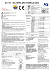
Safety during transportation and storage, as well as the convenience
of working with the device is provided by the original laying, which
consists of two parts: the upper (extracted from the case) and lower
(non-removable).
Figure 1
Laying of ST031M accessories is presented in Figure 3.
Each component, supplied with ST031M, has its own individual place.
To avoid mechanical damage, the device and its components must be
placed in accordance with the standard laying scheme.
Figure 2
Figure 3
Page 5 of 42
2.2.2. Delivery set
ST031M delivery set includes:
1.
2.
3.
4.
5.
6.
7.
8.
9.
10.
11.
12.
13.
14.
15.
16.
control, processing and display unit (main unit)
adapter of scanning receiver BWLC031M
low frequency amplifiers adapter BAC031M
extensions to adapters (such as "Crocodile") (2 pcs)
high-frequency telescopic antenna
headphones
adapter to connect the unit to the multi-wire cables
telephone adapter (2 pieces)
cable connector (8x4)
cable connector (8x6)
cable connector (8x8)
charger
cable to connect to a PC
Flash card with software
Carrying case
User manual and device passport.
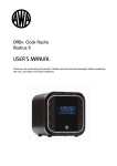
Figure 4. shows the main components of ST031M (numbering corresponds to the numbering of the figure).
Figure 4
Page 6 of 42
2.3. Design of the main control, processing and display unit
The main unit is the main part of ST031M. Figure 5 shows the
appearance of the front, top and bottom panels of the main unit.
At the top of the main unit are:
RF connector for antenna «CH 1"
jack for connecting scanning receiver adapter «CH 2"
jack for connecting sensors and adapters «CH 3"
handle power on / off and volume control «ON / OFF VOL»
The front of the main unit includes:
a. color graphic LCD display (320x240 pixels)
b. power indicator «PWR»
c. two windows of infrared transmitters for wireless
headphones;
d. 12 keys membrane keyboard.
Keys assignment:
F1 F2
F3 F4
Group function buttons. Their function varies
depending on the mode ST031M and indicated
on the display directly above the button.
Buttons to change settings.
ENTER
ESC
FUNC
HELP
Confirm the selected option button / mode.
Button to return to the previous mode, or
cancel the command.
Additional functional button. Provides access to
additional features.
Contexts tips.
More detail button assignments will be presented in the description
of controls and indicators in Section 2.
Bottom panel has:
Headphone jack «PHONE»
Digital port for connection of external digital devices «EXT»
Socket for connecting to a PC «USB»
Socket to connect power supply / charger «DC5V»
Figure 5
Page 7 of 42
3. ST031M operation modes
Systemotechnical and software foundation, incorporated in the design and operation of the device algorithms
make it possible to apply it in the following modes:
selective high-frequency electromagnetic field detector (in the frequency range 140-4500MGts);
Scanning Analyzer for wire lines (in the frequency range of 0.05-30MHz);
Amplifier of low-frequency signals (in the frequency range 0.02-100kHz).
When connecting one or another external device, you must manually chose appropriate mode of operation.
3.1. Switching-on ST031M
Switching the device On/Off is made by rotating volume knob «ON / OFF VOL», located on the top panel (Fig. 5).
To access the "Select Channel" mode, press any button on a ST031M keyboard.
3.2. Mode "Channel selection"
"Channel selection" is primary menu where user can
chose operating mode or set the system configuration.
The screen in the "Channel selection" is shown in
Figure 7.
The numbers indicated in the figure:
1. System information text
2. the name of the current mode
3. Battery charge indicator
4. time display (hh: mm)
5. menu “Chose mode”
6. the menu item "Channel 1"
7. the menu item "Channel 2"
8. the menu item "Channel 3"
9. the menu item "Settings"
10. currently selected menu item
11. function keys assignment
12. function name assigned to button F1
13. function name assigned to button F2
14. function name assigned to button F3
15. function name assigned to button F4
2
1
3
4
00:00
SEL EC T C H A N N EL
5
6
7
C h a n n e l 1 (1 4 0 ...4 4 2 0 М H z )
10
C h a n n e l 2 (0 ,0 5 ...3 0 М H z )
8
C h a n n e l 3 (0 ,0 2 ...1 0 0 К H z )
9
Se ttin g
11
Channel 1 Channel 2 Channel 3
12
13
14
Figure 77
Figure
Page 8 of 42
Setting
15
Available functions
Menu item selection
Activating selected mode
Available modes
"Channel 1" high frequency selective detector
(140- 4200 MHz)
"Channel 2" scanning receiver (0.05 ... 30 MHz)
"Channel 3" low frequency amplifier
"Settings" (time, date, language, infrared headset)
Key
ENTER
F1 or menu button pos.6 Fig.7
F2 or menu button pos. 7 Fig.7
F3 or menu button pos. 8 Fig.7
F4 or menu button pos. 9 Fig.7
3.2.1. "Settings" mode
In the "Settings" menu user can set following system parameters:
Time
Date
Language menu
Enable / disable the IR headset.
00:00
SET T IN G S
Tim e
Setting system time
Press button F4 or chose appropriate menu item in the "Channel
Selection" mode.
To adjust the time select menu item in the box that says „Time“ and
presses ENTER.
In the window that appears, chose between hours or minutes (Fig. 9)
using the buttons LEFT or RIGHT. Use buttons UP or DOWN to set the
desired value. Confirm set time by pressing button ENTER.
If you press the ESC button, the unit exit without saving your changes.
New settings will be stored in memory even when power is turned
off.
Setting system date
To adjust the time select menu item in the box that says "Date" and
press ENTER.
In the window that appears, set the required parameters (similar to
how setting time)
Confirm set values by pressing ENTER. Tto return to the Mode menu
"Settings" press button ESC.
D a te
Я зы к/ L a n g u a g e
IR -h e a d s e t
Figure 8
Figure 9
Figure 10
Page 9 of 42
EN G
Selecting the Interface Language
The device has English and Russian language interface (the default is Russian).
To change language select menu item "Язык / Language” (Fig. 8) and press ENTER. In this menu, chose “RUS” or
“EN”.
Activating IR headphones
In addition to wired headphones, the instrument provides possibility to use wireless IR headphones. By default,
the IR transmitter is off. In order to turn them on in the mode menu "Settings" chose "IR Headset" and press
ENTER. Choose between IR mode by pressing ENTER button: - IR transmitter is disconnected or
- IR
transmitter is active. Press ESC to return to previous mode.
3.3. "CHANNEL 1" mode
Selective HF Detector
In this mode user can detect and identify radio signals in the
frequency range from 140 to 4420 MHz, as well as to localize the
sources of such signals, located in the inspected areas.
00:00
C H A N N EL 1
1
3
Ra nge : 1 4 0 -4 4 2 0 M Hz
S te p: 4 0 M Hz
M a rk e r: 2 4 6 0 M Hz
2
dB
4
50
3.3.1. "Panorama" mode
This mode is the base for selective RF detector. Mode is activated in
"Channel selection" menu by pressing the F1 key or by selecting the
menu item "Channel 1".
5
40
6
30
7
20
10
The screen is shown in Fig. 11.
8
140MHz
Diff .
mode
2270MHz
FIND
Wireless
Comm.
10
Figure 11
The numbers indicated in the figure:
1.
2.
3.
4.
5.
6.
7.
8.
9.
10.
11.
value of lower and upper bounds of the range panorama
value of scan step
frequency corresponding to the position of the marker on display
screen marker
max. signal level at a given frequency for the time of the session (maroon color)
pulse component of the signal (red color)
constant component of the signal (green color)
value of the lower boundary frequency of the panorama
value of the upper boundary frequency of the panorama
value of the center frequency of the panorama
indicator showing current viewing band in comparison to maximum possible.
Available functions
Changing the scanning step and limits the range of
frequencies: 1, 2, 5, 10, 20, 40 MHz
Move display marker
Show context tips
Available modes
Key
UP or DOWN
LEFT or RIGHT
HELP
Page 10 of 42
4420MHz
Fix.
Freq.
9
11
"Differential mode"
"SEARCH"
"Wireless networks"
"Fixed frequency"
Exit from current mode
To “Chose channel” mode
F1
F2
F3
F4
ESC
3.3.2. "Differential" mode
In this mode, the signal levels, obtained in the "Panorama," taken as
"zero" and displays only the exceeding set signal level. Enabling - the
F1 key from the "Panorama" mode.
Indication of switch-on - change the color labels "Diff. mode" from
yellow to orange and lightening the background color of the label
(item 4 in Fig. 12)
The screen of the differential mode is shown in Figure 12.
Numbers indicated in the figure:
1. maximum signal level for the entire session observation for
a given frequency (maroon color)
2. indication of pulse signals (yellow color)
3. indication of the average signal level (purple color)
4. Indicates if differential mode is active.
00:00
C H A N N EL 1 :
Ra nge : 1 4 0 -4 4 2 0 M Hz
S te p: 4 0 M Hz
M a rk e r: 2 4 6 0 M Hz
dB
50
1
40
30
2
3
20
10
140MHz
4
Diff .
mode
2270MHz
FIND
Wireless
Comm.
Figure 12
Available functions
Changing the scanning step and limits the range of
frequencies: 1, 2, 5, 10, 20, 40 MHz
Move display marker
Show context tips
Available modes
"Panorama mode"
"SEARCH"
"Wireless networks"
"Fixed frequency"
Exit from current mode
To “Chose channel” mode
To “Panorama” mode
Key
UP or DOWN
LEFT or RIGHT
HELP
F1
F2
F3
F4
ESC
F1
Page 11 of 42
4420MHz
Fix .
Freq.
3.3.3. "Fixed Frequency" mode
This mode is designed for fine-tuning to the frequency of the detected
signal frequency, as well as to locate the source.
Mode activation is done from the "Panorama" mode by pressing button
F4
Mode screen shown in Figure 13.
The numbers indicated in the figure:
1. the value of center frequency of the signal (corresponding to the
frequency which was set in "Panorama" or "Diff. Mode" modes);
2. the value of bandwidth (corresponding to the value set in
"Panorama" or "Diff. Mode" modes);
3. max. signal level for the entire observation session
4. an indicator of relative changes in signal level (shown in red pulse
component)
5. an indicator of relative changes in signal level (shown in green DC
component).
Available functions
Monitoring changes in the relative signal level of the
indicator (item 4, 5, Figure 13)
Listening to the demodulated signal on speaker or
headphones
Adjust the center frequency of the signal with a step
equal to the bandwidth (Figure 13 item 1)
Changing the bandwidth: 1, 2, 5, 10, 20, 40 MHz (Fig. 13
key 2)
"Zeroing" the relative signal level, "Const. zero "
Show context tips
Available modes
“Oscilloscope”
Return to “Panorama” or “Diff. Mode” mode
5
Set “0"
OSC
Figure 13
C H A N N T L 1 : O SC
T im e / div:
dB / div:
V pp
LEFT or RIGHT
UP or DOWN
F1
HELP
Screen sub modes "Oscilloscope" is presented in Figure 14.
The numbers indicated in the figure:
1. value of dividing the time axis
2. value of the amplitude axis (dB)
3. measured value of signal amplitude (dB)
Key
LEFT or RIGHT
UP or DOWN
HELP
ESC
Page 12 of 42
2
4
1
3
F2
ESC
00:00
Fr e q : 391 .0
M Hz
B a nd w id th: 1 M Hz
3
Key
"Oscilloscope" Sub mode
Available functions
Acoustic control of demodulated signal
Visual inspection of demodulated signal waveform
Changing the scale interval of the time axis: 100,
200, 400, 800 μs / div, 1, 3, 6 ms / div
Scale change of fission axis amplitude: 2.5 or 12,5 dB
/ div
Call of contexts tips
Exit to previous mode
C H A N N EL 1 : F IX .
1
Figure 14
00:00
2
3.3.4. "SEARCH" Mode
Automatic detection of signal levels that exceed an adaptive threshold.
The search is performed in frequency range defined in the "Panorama"
or "Diff. regime." modes.
When you activate this mode (press F2 in "Panorama" mode) message is
briefly displayed on screen accompanying the process of signal detection
(Fig. 15).
Upon completion of the search process, forming a table presented in
Figure 16, where the numbers denote:
1. total number of detected signals
2. number of detected signal in table
3. central frequency of detected signal
4. relative level of detected signal
5. additional information about the signal
6. position indicator line
7. indicator of changes in the relative level of the selected signal
(shown in green DC component)
8. indicator of changes in the relative level of the selected signal
(red shows the dc component).
00:00
C H A N N EL 1 : L is t
1
2
3
4
5
T o ta l: 10 s igna ls
1
189 MHz 16 dB
TV ch6
2
903 MHz 14 dB
GSM900 mob
3
943 MHz 30 dB
GSM900 base
4
946 MHz 12 dB
GSM900 base
5
954 MHz 24 dB
GSM900 base
6
1506 MHz 16 dB
unknow
7
1523 MHz 10 dB
unknow
8
1540 MHz 12 dB
unknow
7
8
Skip
Status
Analysis
Figure 16
If you find air television signals, digital communication base stations and some other standard signals, the
additional information (item 5 Figure 16) specifies the type of data signals, the color of the labels in a row - the
green, which corresponds to the status of "known" (not dangerous) signal.
Upon detection of signals of digital mobile communications in the additional information (item 5 Figure 16)
specifies the type of data signals, the color of text boxes in a row - red, which corresponds to the status of
"dangerous" (potentially dangerous) signal.
Upon detection of signals of a type that cannot be identified automatically, the additional information (item 5
Figure 16) indicates «unknown», while the color labels in a row - white, which corresponds to the status of
"unknown" signal.
At its discretion, the user can change the status of the signals detected by manually.
Available functions
The choice of the signal in the list. Selected signal is
displayed as a highlighted line
Listening to the selected demodulated signal on the
speaker or headphones.
Monitoring changes in the relative signal level of the
indicator (item 7, 8, Fig. 16)
Removing the signal from the list
Assignment of signal status. The options are:
"Dangerous" - red label
"Known" - green label
"Unknown" - white label
Call of contexts tips
Available modes
"Analysis"
Output mode "Panorama" without saving results
Key
UP or DOWN
F1
Press F2
HELP
F3
ESC
Page 13 of 42
6
3.3.5. "Analysis" mode
In general, the work unit in the "Analysis" mode is similar to working in
the "Fixed rate" mode (p.2.3.3), except that in this case there is a
possibility to save changes.
Mode screen "Analysis" presented at Fig.17.
The numbers indicated in the figure:
1. value of the center frequency of the selected signal;
2. the value of fixed bandwidth;
3. max. value of the signal level at a given frequency for the entire
session of observation;
4. an indicator of changes in the relative level of the selected signal
(shown in red pulse component);
5. an indicator of changes in the relative level of the selected signal
(shown in green DC component).
C H A N N EL 1 : A n a ly s is
1
00:00
Fr e q : 191.0
M Hz
B a nd w id th: 1 M Hz
2
3
4
5
Set “0"
OSC
Save
changes
Back to
list
Figure 17
Available functions
Control of the relative signal level according to the indicator (item 3, 4, Figure 17)
Listening to the demodulated signal on speaker or headphones
Adjust the center frequency with a step equal to the bandwidth
Changing the bandwidth: 1, 2, 5, 10, 20, 40 MHz
"Zeroing" the relative level of the selected signal, "Setting zero"
Save the changed value of the frequency of returning to the table of detected signals
Call of contexts tips
Available modes
"Oscilloscope"
Exit from current mode:
to the table of detected signals without saving the changed value of the center
frequency of the signal
to the table of detected signals while preserving the values of the modified center
frequency of the signal
Key
LEFT or RIGHT
UP or DOWN
F1
F3
HELP
F2
F4 or ESC
F3
"Oscilloscope" Submode
Screen "Oscilloscope" submode is presented in Figure 18.
The numbers indicated in the figure:
1. value of dividing the time axis
2. value of amplitude axis scale (dB)
3. measured value of the signal amplitude (dB)
Available functions
Acoustic control of demodulated signal
Visual inspection of demodulated signal waveform
Changing the scale interval of the time axis: 100,
200, 400, 800 μs / div, 1, 3, 6 ms / div
Scale change of fission axis amplitude: 2.5 or 12,5 dB
/ div
Call of contexts tips
Exit to previous mode
C H A N N T L 1 : O SC
1
3
T im e / div:
dB / div:
V pp
Key
LEFT or RIGHT
UP or DOWN
HELP
ESC
Page 14 of 42
Figure 18
00:00
2
3.3.6. "Wireless Networks" mode
Entrance to the mode from the "Panorama" - the button F3
Mode screen control of wireless networks is shown in Figure 19.
The numbers indicated in the figure:
1. Name of a standard digital signal
2. Indicator of the relative signal level.
W IRE L E S S CO M M
1
00:00
CDMA450 base
CDMA450 mob.
2
GSM900 base
GSM900 mob.
GSM1800 base
GSM1800 mob.
Available functions
Evaluation of the relative levels of the
selected wireless network standards
Call of contexts tips
Available modes
“Standarts”
Exit to previous mode
3G base
Key
3G mob.
DECT base
DECT mob.
Bluetooth
HELP
WIFI.
4G
F1
ESC
Sub mode "Standards"
Sub mode is used to select specific standards for digital communications
for their monitoring in the "Wireless Networks" mode.
The screen in the "Standards" presented at Figure 20.
The numbers indicated in the figure:
1. Name of a standard digital signal
2. a sign of disconnection / connection of a standard (X / √)
3. Table pointer.
Standards
Figure 19
W IRE L E S S CO M M
1
CDMA450 base
00:00
2
CDMA450 mob.
GSM900 base
GSM900 mob.
GSM1800 base
GSM1800 mob.
3G base
3G mob.
Available functions
Move cursor
Switch standarts “ON” or “OFF”
Select ALL standarts
Call of contexts tips
Exit to previous mode “Wireless networks”
Key
UP or DOWN
ENTER
F2
HELP
ESC/F1
DECT base
DECT mob.
Bluetooth
WIFI.
4G
EXIT
Select
all
Figure 20
Page 15 of 42
3
3.3.7. Recommendations for the use ST031M in selective RF detector mode ("Channel 1")
Using ST031M in different modes of selective HF detector is focused on the detection, identification and
localization of special technical means of obtaining secret information (STMOSI), transmitting the signal off-site
search in the frequency range 140-4200 MHz. It should be understood that the device can detect only "active"
STMOSI, ie working at the time of transfer.
Unique features implemented in ST031M selective detector are:
The ability to detect signals exceeding the threshold in an adaptive automatic mode with the formation of
a list of these signals. The list indicates the most important information about the signal (center
frequency, level, information on the possible type of signal). In addition, if the frequency of the detected
signal coincides with the frequencies of known signals (broadcast stations, base stations, communications
systems, etc.), it is automatically assigned the status of "known", ie certainly not "dangerous". When a
match is the central frequency of the detected signal with frequencies typical for mobile digital
communications, such signals automatically is assigned the status of "dangerous" because it can be
signals of wireless microphones that use the channel same as a standard digital protocols.
The presence of differential treatment makes it possible-selected signals, the sources are located in the
near zone, ie on-site search.
Ability to control signal at a fixed frequency (modes' Fix. Frequency "and" Analysis "). This greatly
simplifies the process of localizing the source of the signal, even against the more powerful signals.
Ability to listen to the acoustic information on the built-in speaker or headphones allows operator to
identify the signals. If you set the center frequency of coincidence with the frequency of wireless
microphone located in the premises (with not encoded transmission), the headphones will hear the noise
of the room. To identify the source of the detected signal is recommended that you create in a room
called "Control the sound." The source of this sound can serve as a tape recorder, CD / DVD player or a
specific source of the reference tone. Should not be used for this purpose the television or radio.
Should be considered dangerous signals:
-
demodulated signals are correlated with the signal source reference tone (this is typical for analog
microphone with "unencrypted transmission channel and a relatively simple types of encoding);
frequencies do not coincide with the frequencies of TV channels, radio and other "known" sources;
levels of which vary considerably when entering and navigating through the object being tested (with high
probability the sources of these signals are close to the device).
In accordance with the characteristics of the selective RF detector, in general, there are three main options for
transmitting STMOSI search:
-
Search using the automatic mode;
Search in manual mode;
Search for digital mobile communications and STMOSI, based on them.
The proposed further uses of ST031M are typical and may be adjusted depending on the characteristics of the
object and the challenges faced by search operators.
Page 16 of 42
3.3.7.1. Search using automated signal detection mode.
This search option is essential. Its main advantages - simplicity and minimal detection time. Recommended for
use on most sites, provided the low and medium levels of radio spectrum load.
No.
1.
2.
3.
4.
5.
6.
Action
Inside of the scanned
area connect the RF
antenna to the "SH1"
and headphones to the
«PHONE» at the bottom
of the unit
Switch-on the device
Enter into the "Channel
Selection" mode
Enter into the "Settings"
mode (if required to
change settings)
Perform the necessary
settings change and exit
the into the "Channel
selection" mode
Enter into the "Channel
1" mode
Control element
Preparation
Turn the volume control
clockwise.
Press any key on the keyboard
Two ways:
- With the buttons UP or DOWN
set the cursor to the "Settings"
and press ENTER;
- Press the F4 button
Indication
Splash screen. Figure 6.
Screen "Channel selection" mode.
Figure 7.
Screen "Settings" mode. Figure 8.
In accordance with Clause 2.2.1.
Two ways:
- With the buttons UP or DOWN
set the cursor to the
"Channel 1" and press ENTER;
- Press F1 button
Signal detection
F2 button
7.
Enable automatic
search mode
8.
Select signal
9.
Select mode “Analysis”
Use UP or DOWN
set table pointer to a string
containing information about
the signal of interest.
Button F3
10.
Adjust the center
frequency and
bandwidth signal.
adjustment:
frequency - LEFT or RIGHT
bandwidth - UP or DOWN
Page 17 of 42
Basic mode selective RF Detector
"Panorama" Figure 11.
The message as in Fig.15 will be shown
on screen.
Upon completion of the automatic
search, results will be generated and
presented on-screen table (list) of
detected signals, arranged in ascending
order of their center frequency.
By default, cursor is located on the first
row of the table. Fig.16.
In headphones listen to demodulated
signal. The indicator (position 7, 8,
Fig.16) shows the relative level of
constant and pulsed signal components
Screen "Analysis." mode Figure 17.
In headphones listen for demodulated
signal.
The display shows the relative level of
constant and pulsed signal components
By observing changes in the relative
level of the signal and listening to the
demodulated signal, set the frequency
and the bandwidth corresponding to
11.
12.
13.
14.
15.
16.
Exit from the "Analysis"
to the table of detected
signals
Changing status of the
signal
Remove signal from list
Chose signal
Switch-on “Analysis”
mode
Setting current signal
level as “Zero”
Save changes - F3 button
Without saving changes Button F4 or ESC
Successive pressing F2
the maximum signal level and the best
signal quality in the headphones
When you press F3, detected signal
parameters in the table will change in
accordance with the adjustments.
Font color changes
Use UP or DOWN to set the
The line will be removed from the list of
table cursor on the signal you
detected signals.
want to delete. Press the F1
button
Signal source localization
Same as in step 8
Same as in step 9
Button F1
The relative level of the signal is taken
as "zero", while the level of the
indicator will be significantly reduced.
17. Locate place of signal
By observing changes in the relative
source
level of the indicator, find place where
indicator shows maximum level.
Repeat steps 14-17 for all "dangerous" and "unknown" signals in the table.
Notes:
If the list of detected signals contains signals whose frequency is within the 140-280 MHz range, it might be that
these signals are the upper harmonics of high-power signals, with central frequencies below 140 MHz. This
circumstance is due to the fact that the lower limit of the working range of the selective RF detector is 140 MHz
and the device cannot record the signal at frequencies below this limit. However, their harmonics are detected
reliably within the operating range.
3.3.7.2. Search in manual mode
This option is recommended to apply in a complex electromagnetic enviroment. The advantages of this method
include the possibility of using selective RF detector in a differential mode, which allows distinguishing between
external and internal signals (sources which are located in the near zone). However, the search takes longer than
in the automatic mode.
No.
1.
2.
3.
4.
Action
Outside of the scanned
area connect the RF
antenna to the "SH1"
and headphones to the
«PHONE» at the bottom
of the unit
Switch-on the device
Enter into the "Channel
Selection" mode
Enter into the "Settings"
mode (if required to
change settings)
Control element
Preparation
Turn the volume control
clockwise.
Press any key on the keyboard
Two ways:
- With the buttons UP or DOWN
set the cursor to the "Settings"
Page 18 of 42
Indication
Splash screen. Figure 6.
Screen "Channel selection" mode.
Figure 7.
Screen "Settings" mode. Figure 8.
and press ENTER;
- Press the F4 button
5.
6.
Perform the necessary
settings change and exit
the into the "Channel
selection" mode
Enter into the "Channel
1" mode
7.
Enable “Differential
Search” mode
8.
9.
Enter to inspected room
Monitor change in
signal levels on device
screen.
If increase in the levels
are observed, set screen
marker on to the peak
of signal.
Switch-on “Fixed
frequency” mode
Fine-tuning
In accordance with Clause 2.2.1.
Two ways:
- With the buttons UP or DOWN
set the cursor to the
"Channel 1" and press ENTER;
- Press F1 button
F1 button
Basic mode selective RF Detector
"Panorama" Figure 11.
Differential search screen as in Fig.12
The signal levels obtained in the
"Panorama" mode are taken as "zero."
The screen displays deferential
spectrum range (average - lilac color,
pulse components - yellow).
Purple color on the screen shows the
maximum signal levels obtained in the
"Panorama"
Signal detection
10.
11.
Buttons LEFT or RIGHT
Press F4
Adjustment:
Frequency – buttons LEFT of
RIGHT
Bandwidth – UP or DOWN
“Fixed frequency” control mode screen.
Figure 13.
Watching the change in the relative
level of signal and listening to
demodulated signal in headphones, set
the frequency and bandwidth,
corresponding to the maximum level
and the best sound quality.
Signal source localization
12. Zeroing relative signal
Button F1
The relative level of the signal is taken
level
as "zero." Levels decrease significantly
on the display.
13. Find location of the
By observing change of the indicator,
signal source
find area in the room where the
relative signal level shows maximum
level.
Repeat operations described in steps 9-13 for all signal levels which rose at the entrance to the inspected
premises.
Notes:
For a detailed assessment of the busiest parts of the spectrum range and fine-tune the display marker in the
modes of the "Panorama" and "Differential mode" it is useful to reduce on-screen viewing band (button UP).
Page 19 of 42
In assessing the demodulated signals in the "Fixed frequency" mode it is recommended to use “Oscilloscope"
submode.
During localization of signal sources in the "Fix. frequency" mode, operator should pay attention to changes in
levels of continuous and pulse current signal components (red and green), with respect to the maximum recorded
level (maroon color). In the case of moving away from the source of signal, it is clearly visible decrease in the
levels of the current signal on the background of the maximal recorded level and, vice versa.
3.3.7.3. Search in “Wireless Networks” mode
"Wireless Networks" mode is designed to detect signals of the most common digital communications and data
transmission systems. Mobile devices of these systems can be used as STMOSI. Selective RF detector ST031M
allows not only to identify the signals of these devices, but also to localize the sources of such signals in the
inspected area.
No.
1.
2.
3.
4.
5.
6.
7.
8.
9.
10.
11.
Action
Inside of the scanned
area connect the RF
antenna to the "SH1"
and headphones to the
«PHONE» at the bottom
of the unit
Switch-on the device
Enter into the "Channel
Selection" mode
Enter into the "Settings"
mode (if required to
change settings)
Perform the necessary
settings change and exit
the into the "Channel
selection" mode
Enter into the "Channel
1" mode
Enable “Wireless
networks” search mode
Enter “Standarts”
submode
Select wireless devices
Exit from “Standarts”
submenu
Evaluation of selected
standarts
Control element
Preparation
Turn the volume control clockwise.
Press any key on the keyboard
Two ways:
- With the buttons UP or DOWN
set the cursor to the "Settings" and
press ENTER;
- Press the F4 button
In accordance with Clause 2.2.1.
Indication
Splash screen. Figure 6.
Screen "Channel selection" mode.
Figure 7.
Screen "Settings" mode. Figure 8.
Two ways:
Basic mode selective RF Detector
- With the buttons UP or DOWN set
"Panorama" Figure 11.
the cursor to the "Channel 1" and
press ENTER;
- Press F1 button
Wireless networks signal detection
F3 button
“Wireless networks” screen will
appear Fig. 19
Button F1
“Chose Wireless Devices” screen
Buttons UP or DOWN. Select
corresponding menu item. ENTERactivate/deactivate selected
standart.
F1 button
Page 20 of 42
- standart will be included into
search list
- standart will be excluded
from search list
“Wireless networks” screen
containing only selected standarts.
According to selected signals levels
indicator it is possible to
12.
determine if signal sources are in
near zone.
By looking at changes of signal
level, determine location in the
room where this level has
maximum value. Further
localization is performed by
physical inspection of area.
Localizing signal source
It is recommended to activate following signal types while performing search:
CDMA450 mob
GSM900 mob
GSM1800 mob
3G mob
DECT mob
Bluetooth
WIFI
4G
The use of these devices as STMOSI is most likely.
WARNING!
It is possible that WIFI devices can be identified incorrectly as Bluetooth devices!
Page 21 of 42
3.4. "CHANNEL 2" mode. Scanning receiver
In scanning receiver ("Channel 2») mode ST031M can detect STMOSI signals, transmitting information by power
and low-wire lines in the frequency range from 0.05 to 30 MHz.
For convenience user interface of the channel is made by analogy with the interface of selective RF detector.
Although there are specific modes and features common to wired receivers.
BWLC031M adapter is used to connect ST031M scanning receiver to inspected wire lines.
3.4.1. "Panorama" mode
This mode is the base for the scanning receiver. Mode is activated while in
"Channel selection" by pressing F2 or by selecting the menu item
"Channel 2".
The screen is shown in Fig. 21.
The numbers indicated in the figure:
1. value of lower and upper bounds of range panoramas
2. value of scan step
3. frequency corresponding to the position of the marker display
4. screen marker
5. component of the signal pulse (red)
6. constant component of the signal (green)
7. value of the lower frequency boundary of the panorama
8. value of the upper frequency boundary of the panorama
9. value of the central frequency of the panorama
10. indicator, showing lower and upper range of active bandwidth.
Available functions
Changing the scanning step and frequencies band
limits: 28, 140, 280 kHz
Move screen cursor
Show context tips
Available modes
“Differential mode”
“Search”
“Attenuator 20 dB”
“Fixed frequency”
Exit from current mode
To the “Chose channel” mode
Key
UP or DOWN
LEFT or RIGHT
HELP
F1
F2
F3
F4
ESC
Page 22 of 42
00:00
C H A N N EL 2 :
1
3
Ra nge : 0 .0 5 -3 0 M Hz
S te e p: 2 8 0 k Hz
M a rk e r: 1 5 .1 7 M Hz
2
dB
4
50
40
5
30
6
20
10
7
0.05MHz
Diff.
mode
15.02MHz
FIND
АТТ 20dB
9
Figure 21
30.00MHz
Fix .
Freq.
8
10
3.4.2. "Differential" mode
In this mode, the signal levels obtained in the „Panorama“ taken as „zero“
and display only the levels of excess.
00:00
C H A N N EL 2 :
Ra nge : 0 .0 5 -3 0 .0 0 M Hz
S te e p: 2 8 0 k Hz
M a rk e r: 1 5 .1 7 M Hz
dB
Enabling – press F1 key from the "Panorama" mode.
50
40
Indications include - change the color labels "Diff. regime" from yellow to
orange and lightening the background color of the label (position 3 in
Fig. 22)
30
1
20
10
2
The screen of the differential mode is shown in Figure 22.
The numbers indicated in the figure:
1. Display of pulse signals (yellow)
2. Display of the average signal level (purple color)
3. Display the activation of the differential mode.
Available functions
Changing the scanning step and frequencies band limits: 28, 140, 280 kHz
Move screen cursor
Show context tips
Available modes
“Panorama”
“Search”
“Attenuator 20 dB”
“Fixed frequency”
Exit from current mode
To the “Chose channel” mode
0.05MHz
3
Diff .
mode
15.02MHz
FIND
ATT 20dB
30.00MHz
Fix .
Freq.
Figure 22
Key
UP or DOWN
LEFT or RIGHT
HELP
F1
F2
F3
F4
ESC
"Attenuator" function
The function allows you to reduce the input signals at 20dB. This is necessary in cases, if the levels of interference
signals in tested line are too high.
Enable - F3 button in the "Panorama" mode.
Activating attenuation in “Differential mode” leads to the exit from this mode to the "Panorama" mode. However,
when the attenuator is active, "Differential mode" is available.
Also, when the attenuator is active, following modes are available:
automatic search ("Search")
control signal at a fixed frequency ("Fix. frequency")
Function activation indicator - change color of the text “ATT 20 dB” in the function assignments keys line from
yellow to orange, and lightening the background color of the lettering.
Page 23 of 42
3.4.3. "Fixed Frequency" mode
This mode is designed for fine-tuning the central frequency of
the detected signal.
Sign of the modes of the "Panorama" or "Differential mode" - the
F4 button
Mode screen shown in Figure 23.
The numbers indicated in the figure:
1. the value of signal center frequency (corresponding to
the frequency at which the marker was set in
"Panorama" or "Diff. Mode" modes)
2. demodulator (AM or FM)
3. an indicator of relative changes in signal level (shown in
red pulse component)
4. an indicator of relative changes in signal level (shown in
green DC component).
00:00
C H A N N EL 2 : F IX
1
Fr e q : 14.878
M Hz
M o d ula tio n: A M
2
3
4
AM
OSC
Figure 23
Available functions
Monitoring changes in the relative signal level
of the indicator (item 3, 4, Fig. 23)
Listening to the demodulated signal on speaker
or headphones
Adjust the center frequency of the signal with a
step equal to the bandwidth (position 1 Figure
23)
Change demodulation type (AM/FM)
Show context tips
Available modes
“Oscilloscope”
Exit to the previous mode ("Panorama" or "Diff.
Mode")
Key
C H A N N T L 2 : O SC
1
3
00:00
T im e / div:
dB / div:
V pp
2
LEFT or
RIGHT
F1
HELP
F2
ESC
Figure 24
Submode "Oscilloscope"
"Oscilloscope" submode sreen presented at Figure 24.
The numbers indicated in the figure:
1. set the value of scale of time axis
2. set the value of scale of amplitude axis (dB)
3. measured value of the signal amplitude (dB).
Available functions
Acoustic control of demodulated signal
Visual control of demodulated signal waveform
Changing the scale interval of the time axis: 100, 200, 400, 800 μs / div, 1, 3, 6 ms / div
Changing division scale of the amplitude axis 3 or 15 dB / div
Show context tips
Exit to “Fixed frequency” mode
Page 24 of 42
Key
UP or DOWN
LEFT or RIGHT
HELP
ESC
3.4.4. "SEARCH" mode
Automatic detection of signal levels that exceed an adaptive threshold.
The search is performed in the frequency range defined in the
"Panorama" or "Diff. mode" modes.
When you activate SEARCH mode (button F2 from "Panorama" mode)
message is displayed on screen that accompanies the process of signal
detection (Figure 25).
Upon completion of the search process, forming a table presented in
Figure 26, where the numbers denote:
1. total number of detected signals
2. number of detected signal in table
3. the central frequency of the detected signal
4. the relative level of the detected signal
5. Additional information about the signal
6. Current position indicator line in the list
7. an indicator of changes in the relative level of the selected
signal (shown in green DC component)
8. an indicator of changes in the relative level of the selected
signal (shown in red pulse component)
9. Display currently active demodulator (AM / FM).
Figure 25
00:00
C H A N N EL 2 : L is t
1
2
3
4
T o ta l: 5 s igna ls
1
0.12 к Hz 31 dB
df: 10 kHz
2
0.45 kHz 20 dB
df: 10 kHz
3
0.89 kHz 19 dB
df: 10 kHz
4
2.44 kHz 21 dB
df: 10 kHz
5
5.87 kHz 20 dB
df: 10 kHz
6
5
7
Skip
Status
Analysis
Figure 26
Available functions
The choice of the signal in the list. Selected signal is displayed as a
highlighted line
Listening to the selected demodulated signal on the speaker or
headphones.
Monitoring changes in the relative signal level of the indicator
(item 7, 8)
Remove signal from the list
Assignment of signal status. The options are:
"Dangerous" - red label
"Known" - green label
"Unknown" - white label
Switch demodulator mode AM/FM
Call of contexts tips
Available modes
"Analysis"
Output mode "Panorama" without saving results
Page 25 of 42
Key
UP or DOWN
F1
Press F2 several times to choose
appropriate status
F4
HELP
F3
ESC
АМ
8
9
3.4.5. "Analysis" mode
The regime is intended to clarify the parameters of the signals detected
in the automatic mode. In general, the work unit in the "Analysis" is
similar to working in the "fixed rate" (p.2.4.3), except that in this case, it
is possible to save your changes.
Activate “Analysis” mode - press F4 button in "SEARCH" mode.
Mode screen is shown in Fig.27.
The numbers indicated in the figure:
1. value of the center frequency of the selected signal;
2. select demodulator (AM or FM);
3. an indicator of changes in the relative level of the selected signal
(shown in red pulse component);
4. an indicator of changes in the relative level of the selected signal
(shown in green DC component).
Available functions
Control of the relative signal level according to the
indicator (item 3, 4, Figure 27)
Listening to the demodulated signal on speaker or
headphones
Adjust the center frequency of the signal (item 1 in
Figure 27
Changing type of demodulator (AM/FM)
Call of contexts tips
Available modes
"Oscilloscope"
Exit from current mode:
to the table of detected signals without saving the
changed value of the center frequency of the signal
to the table of detected signals while preserving
the values of the modified center frequency of the
signal
C H A N N EL 2 : A n a ly s is
1
Fr e q : 10 .30 8
M o d ula tio n:
00:00
M Hz
AM
2
3
4
AM
OSC
Save
changes
Back to
List
Figure 27
Key
C H A N N T L 2 : O SC
1
3
00:00
T im e / div:
dB / div:
V pp
2
LEFT or RIGHT
F1
HELP
F2
F4 or ESC
Figure 28
F3
"Oscilloscope" Submode
Submode is activated from “Analysis” mode by pressing F2 button. Screen "Oscilloscope" submode is presented in
Figure 28.
The numbers indicated in the figure:
1. value of dividing the time axis
2. value of amplitude axis scale (dB)
3. measured value of the signal amplitude (dB)
Available functions
Acoustic control of demodulated signal
Visual inspection of demodulated signal waveform
Changing the scale interval of the time axis: 100, 200, 400, 800 μs / div, 1, 3, 6 ms / div
Scale change of fission axis amplitude: 3 or 15 dB / div
Call of contexts tips
Exit to “Analysis” mode
Page 26 of 42
Key
LEFT or RIGHT
UP or DOWN
HELP
ESC
3.4.6. Recommendations for the use of ST031M in scanning receiver (Channel 2) mode
Using ST031M in scanning receiver mode is focused on the discovery of channels used by special technical means
of obtaining secret information (STMOSI), transmitting the signal off-site by power and low-current lines in the
frequency range 0.05-30 MHz.
As can be seen from the description of modes of scanning receiver, in many respects they are similar to the
modes implemented in a selective high-frequency detector. However, the use of these modes is different in some
way. This is due to the specifics of performing search of wired STMOSI.
For example, using a scanning receiver cannot locate the source of the signal detected by the methods described
in the "Channel 1". The main objective of using a scanning receiver ST031 - the discovery of the fact of illegal
transmission of signals from the scanned area of a wire lines (within the range of operating frequencies, "Channel
2"). These lines can be:
mains
telephone lines
line of security and fire alarm
lines of computer networks
cable television lines
radio retranslation lines, etc.
When analyzing received information, signals to be considered as dangerous:
demodulated signals are correlated with the signal source reference tone set in the scanned area (this is
typical for analog STMOSI, the un encoded transmission channel and a relatively simple types of
encoding);
which levels are much higher than the background noise and interference;
broadband signals.
It is required from operator not only the ability to work with the search appliance, but also the possession of
information about the inspected object:
what types of wire lines are installed in inspected premises;
lines installation scheme;
possibility of unauthorized access to the lines from the outside of inspected premises, etc.
Strict adherence to the rules of electrical safety is very important, when checking lines. Life-threatening voltage is
applied to the device adapter.
In general, the verification of wire lines is as follows:
Scanning frequency range characteristic of the wired STMOSI and detection of the most powerful signals.
Investigation of detected signals (estimated informativeness of demodulated signals, determining the
form of modulation of analog signals and their correlation with the acoustic environment of inspected
premises, analysis of waveforms of digital signals, etc.).
Identification of dangerous signals.
Since the device has two types of search (manual - mode "Panorama" and the automatic - mode "Search"), the
difference in the proposed search options is only in the method of signal detection. Further action on the analysis
and identification of signals in both methods are identical.
Page 27 of 42
The proposed further uses ST031M are typical and may be adjusted depending on the characteristics of the object
and the tasks faced by search operators.
3.4.6.1. Search using automated signal detection mode
This search option is essential. Its main advantages are simplicity and minimal signals detection time.
When checking power lines, it is recommended to search with attenuator switched-on!
No.
1.
2.
3.
4.
5.
6.
Action
Control element
Indication
Preparation
Connect BWLC031M adapter to scanning receiver socket "SH2" (adapter jack and base unit socket are
marked in red), and headphones to the «PHONE» socket in the bottom panel.
WARNING!
Connecting the BWLC031M adapter to the other sockets of ST031M is forbidden!
Switch-on the device
Turn the volume control
Splash screen. Figure 6.
clockwise.
Enter into the "Channel Press any key on the keyboard
Screen "Channel selection" mode.
Selection" mode
Figure 7.
Enter into the "Settings" Two ways:
Screen "Settings" mode. Figure 8.
mode (if required to
- With the buttons UP or DOWN
change settings)
set the cursor to the "Settings"
and press ENTER;
- Press the F4 button
Perform the necessary
settings change and exit
the into the "Channel
selection" mode
Enter into the "Channel
2" mode
7.
Switch-on attenuator
(necessary in case of
checking power lines, in
case of checking low
current lines – depends
on band spectrum load)
8.
Enable automatic
search mode
9.
Select signal
In accordance with Clause 2.2.1.
Two ways:
- With the buttons UP or DOWN
set the cursor to the
"Channel 2" and press ENTER;
- Press F2 button
Button F3
Scanning receiver base mode
"Panorama" Figure 21.
Attenuator indicator becomes active
Signals detection
F2 button
The message as in Fig.25 will be shown
on screen.
Upon completion of the automatic
search, results will be generated and
presented on-screen table (list) of
detected signals, arranged in ascending
order of their center frequency.
By default, cursor is located on the first
row of the table. Fig.26
Detected signals analysis
Use UP or DOWN
set table pointer to a string
containing information about
the signal of interest.
Page 28 of 42
In headphones listen to demodulated
signal. The indicator (position 7, 8,
Fig.26) shows the relative level of
constant and pulsed signal components
10.
Evaluation of
modulation type
Button F4
The default mode is AM. Pressing F4
toggles the demodulator to the FM
(which is displayed on the screen).
Pressing F4 again, returns the AM.
You must connect the various
demodulators to determine which of
them gives better acoustic quality of
the signal.
If the demodulated signal correlates with the acoustic environment in inspected room or control sound,
then it means that STMOSI device is installed in room and transmits information by wire under test. Signal
must be treated as "Dangerous" (button F2).
The localization of such a device can be made by reducing the volume of the control sound source, and
moving it around the room. In this demodulated signal is monitored in the headphones. Approximate
STMOSI installation location will coincide with the place where the demodulated signal had better quality.
In case of detection of broadcast station signals on the known frequencies, such signals can be assigned
with status “Known”, or deleted from the list by pressing F1
If the detected signal is demodulated, and its frequency does not coincide with the frequencies of the
broadcast stations (operating in the scanned frequency range), the signal must be analyzed in more detail.
11. Switch-on “Analyze”
Button F3
“Analyze” screen mode.
mode
Listen to demodulated signal. Indicator
shows constant and impulse
components of the signal.
12. Adjustment of signal
Buttons LEFT or Right
By observing changes in relative level of
central frequency
the signal and listening to the
demodulated signal, set the frequency
corresponding to the maximum signal
level and the best signal quality in the
headphones.
13. Exit from the "Analysis" With saving changes - F3 button When you press F3, detected signal
submode to the table of Without saving changes parameters in the table will change in
detected signals
Button F4 or ESC
accordance with the corrections made.
14. Changing status of the
Successive pressing F2
Font color changes
signal
3.4.6.2. Search using manual signal detection mode
This search option is a subsidiary. Recommended to use on wire lines with high levels of background noise.
No.
1.
2.
3.
4.
Action
Control element
Indication
Preparation
Connect BWLC031M adapter to scanning receiver socket "SH2" (adapter jack and base unit socket are
marked in red), and headphones to the «PHONE» socket in the bottom panel.
WARNING!
Connecting the BWLC031M adapter to the other sockets of ST031M is forbidden!
Switch-on the device
Turn the volume control
Splash screen. Figure 6.
clockwise.
Enter into the "Channel Press any key on the keyboard
Screen "Channel selection" mode.
Selection" mode
Figure 7.
Enter into the "Settings" Two ways:
Screen "Settings" mode. Figure 8.
mode (if required to
- With the buttons UP or DOWN
change settings)
set the cursor to the "Settings"
and press ENTER;
- Press the F4 button
Page 29 of 42
5.
6.
7.
Perform the necessary
settings change and exit
the into the "Channel
selection" mode
Enter into the "Channel
2" mode
Switch-on attenuator
(necessary in case of
checking power lines, in
case of checking low
current lines – depends
on band spectrum load)
In accordance with Clause 2.2.1.
Two ways:
- With the buttons UP or DOWN
set the cursor to the
"Channel 2" and press ENTER;
- Press F2 button
Button F3
Scanning receiver base mode
"Panorama" Figure 21.
Attenuator indicator becomes active
Setting band limits
If the band load range is not uniform, it is recommended to set the range in accordance with the
boundaries of areas of interest. This is convenient in terms of following fine-tuning the marker on the
frequency of the signal of interest.
8.
Setting central
Buttons LEFT or RIGHT
First it is necessary to define the start
frequency of the band
and end frequency range of bandwidth
area in which search will be performed.
Then determine center frequency of
the resulting range. Set the marker to
central frequency.
9.
Band scaling
Buttons UP or DOWN
Set the desired width of the band (with
respect to frequency, corresponding to
position of screen marker).
Compensation of interference signals
Connect one of adapter's probes to one of the wire of two wires line which is under testing.
10. Switch-on differential
Button F1
The level of the previously detected
mode
signals is taken as zero. Display shows
the differential spectrum.
Signals detection
Connect adapter’s second probe of the second wire of the test line. The spectral image on the screen will
change. A screen will show the difference signal levels. In the ideal case, the spectrogram shows signals
characteristic lines tested.
11. "Rough" signal
Buttons LEFT or RIGHT
Set screen market to signal of interest
adjustment
12. Signal control on fixed
Button F3
“Fixed frequency” screen mode
frequency
13. Fine tuning
Buttons LEFT or RIGHT
By monitoring indicator value, set the
frequency where signal level is
maximal.
14. Evaluation of
Button F1
By changing modulation type, achieve
modulation type
best quality of demodulated signal.
If the demodulated signal correlates with the acoustic environment in inspected room or control sound,
then it means that STMOSI device is installed in room and transmits information by wire under test. Signal
must be treated as "Dangerous" (button F2).
The localization of such a device can be made by reducing the volume of the control sound source, as it was
described in earlier.
Repeat steps 11-14 for all powerful signals which appears in differential spectrum.
Page 30 of 42
3.5. "CHANNEL 3" Mode. Low-frequency amplifier.
Low-frequency amplifier of ST031M is designed for detection and qualitative assessment of:
STMOSI channels in the LF range 0.02 - 100 kHz
low-frequency channels of information leakage of natural origin.
In low-frequency amplifier mode, ST031M is connected to the tested wire lines with the help of an adapter
BAC031M.
Enabling LF made from the regime, "Channel selection" when you
select "Channel 3", or by pressing F3.
The screen mode is presented in the form of an oscilloscope (Fig.29)
The numbers indicated in the figure:
1. set the value of time axis dividing
2. vertical scaling of waveform
3. measured value of the signal amplitude (dB)
4. RMS amplitude of the signal
5. Display gain coefficient.
1
3
5
C H A N N EL 3
T im e / d iv: 1.6m s
d B / d iv: x 1
V p p : -68 .3 d B V
R M S: -72.1 d B V
+12dB
Figure 29
Available functions
Acoustic control of demodulated signal
Visual inspection of demodulated signal waveform
Changing the scale interval of the time axis: 100,
200, 400, 800 μs / div, 1, 3, 6 ms / div
Vertical scaling of oscilogram: x1, x2, x4
Setting gain coefficient: +12, +24, +36, +48
Call of contexts tips
Exit to “Fixed frequency” mode
Key
LEFT or RIGHT
UP or DOWN
F1
HELP
ESC
Page 31 of 42
00:00
2
4
Notes for the use of low-frequency modes in the ST031M amplifier (Channel 3)
The use of low-frequency amplifier ST031M allows multiple search functions. Implementations of these functions
are achieved by using special sensors or adapters. In basic ST031M set there is only one adapter - BAC031M.
Other sensors included into ST331 instrument set, which is optional. Reference tone generator is required to
detected signals. The following table lists the major search function of ST031M low frequency amplifier, and
sensors/adapters, through which these functions are implemented.
Search function
Check low-current lines.
Purpose - detection of acoustic signals, correlated
with the reference tone signal
Check of building constructions for the presence of
possible vibroacoustic leakage channel
Check premises for the presence of an acoustic
leakage channel
Check premises for the presence of an infrared
STMOSI channel
Detection of low-frequency magnetic fields,
modulated by reference tone source
Detector/adapter
Adapter BAC031M included with ST031M
Vibro transducer from ST331 optional instrument
set
Testing microphone from ST331 optional instrument
set
Optical IR detector is included into ST331 optional
instrument set
Magnetic antenna is included into ST331 optional
instrument set
The following recommendations apply only to testing of wire lines, as ST031M set includes only wires adapter.
Recommendations for use of other sensors are in ST331 user manual.
No.
1.
2.
3.
4.
5.
6.
7.
Action
Control element
Indication
Preparation
Connect LF amplifiers adapter to socket "SH3" and headphones to «PHONE» socket in the bottom
panel.
WARNING!
ST031M base module must be switched-off while connecting any adapter to "SH3" socket.
Connecting the BAC031M adapter to lines where voltage is more than 120 V is forbidden!
Switch-on the device
Turn the volume control
Splash screen. Figure 6.
clockwise.
Enter into the "Channel Press any key on the keyboard
Screen "Channel selection" mode.
Selection" mode
Figure 7.
Enter into the "Settings" Two ways:
Screen "Settings" mode. Figure 8.
mode (if required to
- With the buttons UP or DOWN
change settings)
set the cursor to the "Settings"
and press ENTER;
- Press the F4 button
Perform the necessary
In accordance with Clause 2.2.1.
settings adjustment and
exit into the "Channel
selection" mode
Enter into the "Channel Two ways:
Base mode of low frequency amplifier
3" mode
- With the buttons UP or DOWN Figure 29.
set the cursor to the "Channel
3" and press ENTER;
- Press F3 button
Connect adapter probes
Demodulated signal oscilogram is
to tested wires
displayed on screen. Listen to
demodulated signal on headphones.
Page 32 of 42
When testing phone lines, computer networks, or other wire lines having RJ45 connectors it is
recommended to use special adapter (position 7 Figure 4).
8.
Adjust amplification
Button F1
In pos.5 Fig. 29 value of the gain is
indicated
Hearing of reference sound on headphones indicates presence of a microphone or microphone effect from
equipment connected to tested lines.
Page 33 of 42
3.6. Operating ST031M with a personal computer
Operate ST031M with a personal computer (PC) by using the program ST031M-Piranha.
Main features:
-
Control device function duplication
Display ST031M graphic information on PC monitor
Archiving of information received from ST031M on PC hard drive
A software upgrade (firmware inside ST031M).
3.6.1. The program ST031M-Piranha
Program installation
Installation file «ST031m_piranha_0_9b.exe» is located on a USB flash card that is included with the device. To
install the software run the file «ST031m_piranha_0_9b.exe» and follow the instructions.
If the base module ST031M is not connected to the computer, status bar indicates status as «Disconnected»
(Figure 30).
The user can only access "Settings" menu item.
Figure 30
Page 34 of 42
Connect ST031M base module to USB port. Switch-on ST031M. Program status bar change status to “Connected”
User can access following menu items:
1. “Modes” – select one of 3 channels
2. “Settings” – chose interface language and automatic updates.
3. “Help” -> “Updates” – update device firmware or PC software.
“Channel 1” mode (corresponds to selective detector HF mode).
“Channel 1” mode can be accessed on menu bar: "Mode" -> "Channel 1" (Figure 31)
In the graphics area of the window displays information corresponding to the "Panorama" mode.
Chose "Search", "Wireless Networks" or "Fixed frequency" mode by pressing the corresponding button on the left
of the graphics area.
When you click on the button with the camera's icon, current image is saved in the folder «Smersh Technics»
(created automatically) on the C drive on your computer HDD.
Created image file has a name like "dd.mm.yyyy chch.mm.ss.jpg" that includes the date and time of the image
(example: 01.01.2012 12.30.00.jpg - picture taken January 1st, 2012 at 12 h 30 minutes. 00 sec.).
Figure 31
When you move the mouse pointer over the graphics area, a line of light gray color is displayed. When you press a
mouse button, marker is set to this line. Scaling (change step) is carried out with the mouse wheel while the
pointer should be in the graphics area.
Page 35 of 42
"Search" mode
Displays table of detected signals (Fig. 32). Skip signal, status change, the transition to the signal analysis mode
and exit to "Panorama" mode of the first channel is accomplished by pressing corresponding button on the left of
the graphics area. When you click on the Excel icon program opens Microsoft Excel (if installed on your
computer). The data are transferred from table to Excel and can be edited later.
Figure 32
"Wireless Networks" mode
Data shown is from the screen of ST031M device (fig. 33). Operator can activate or deactivate detected standarts
on the left part of the screen. Press button with camera icon to save screen image. Click "Back" button to exit to
"Panorama" mode of the first channel.
Figure 33
Page 36 of 42
"Fixed frequency" mode
Window (Fig. 34) consists of two parts. The right side displays information from device screen (continuous and
pulse level of the selected signal). On the left part spectrum is displayed in the selected range of frequencies. You
can change the selected signal by clicking mouse on the appropriate reading. The image can be saved by pressing
the button with the camera icon. Go into the "Oscilloscope" mode by pressing corresponding button on the left of
the graphics area. "Back" button - exit to "Panorama" mode of the first channel.
Figure 34
"Oscilloscope" mode
Screen displays selected signal waveform (Figure 35). Scale screen by using mouse wheel while the mouse
pointer must be inside the graphics area. The image can be saved by pressing the camera icon. Exit to previous
mode (fixed frequency) by pressing "Back".
Figure 35
Page 37 of 42
"CHANNEL 2" mode
Activate mode from main menu: "Mode" -> "2 Channel"
Information from the screen of the device is displayed in graphics area (Fig. 36).
When you move the mouse pointer over the graphics area it displays a line of light gray color. When you press a
mouse button, the marker is set to this line. Scaling (change pitch) is carried out with the mouse wheel while the
pointer should be in the graphics area.
Mode "Fixed frequency" of the second channel is similar to "Fixed rate" of the first channel.
Figure 36
"Search" mode
Displays table of detected signals. Skip signal, change signal status, enter to signal analysis mode and exit to
previous mode of the first channel are accomplished by pressing corresponding button on the left of the graphics
area.
Data can be transferred to Microsoft Excel for later analysis. Pressing "Analysis" button – enter to mode of signal
analysis.
"CHANNEL 3" mode
Display waveform of signal. Scaling (change pitch) is carried out with the mouse wheel while the pointer should
be in the graphics area.
“Settings” menu
Language selection is done in main menu bar choosing "Settings".
"Help" menu
To start update ST031M software execute the command: "Help" -> "Update"
Page 38 of 42
In this mode, checks for new version of firmware and software (if you have an Internet connection). If there is a
new version, a message is displayed and the button "Download" becomes active (Fig.37).
When you click "Download" button, BIOS file saved on your computer at:
C: \ Smersh Technics \ Update.
To install the new firmware, use the ST031M update program.
Figure 37
ST031M update program
Select firmware file by clicking Browse.
Open Smersh Technichs folder on disk C, and then folder Update select firmware file and press Open
Press “Load”. After finishing firmware update, window will close automatically. Switch-off and switch-on the
device as it is suggested on the screen.
Page 39 of 42
4. ST031M power supply
ST031M powered by a built-in lithium-polymer battery. Instrument could be operated when in AC mode (via the
power supply / charging pos. 3 Figure 7).
A fully charged battery ensures continuous operation of the device for up to 7 hours. Charging status is controlled
by the indicator (position 3. Figure 7).
Battery charging is made by means of the block (Fig. 4 item No. 12). Full-charge time - 7 hours.
Connect charging adapter to device «DC 5V» socket on the bottom of the unit and connect charger to the AC
mains (220V/50Hz).
«POWER» indicator states:
Orange – charging;
Green – charging complete;
Batteries can be charged while unit is in operation however charging time increases.
Page 40 of 42
5. Glossary of terms
TSCM – Technical Surveillance Counter Measures
STM – Special Technical Means
STMOSI - Special Technical Means of Obtaining Secret Information
HF – High Frequency
LF – Low Frequency
Page 41 of 42