1
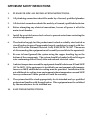
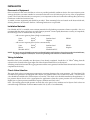
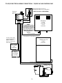
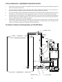
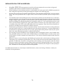
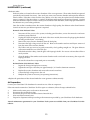
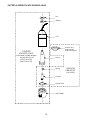
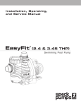
T
E
C
H,
L
L
C .
Ozone Systems
Ozone System
CD-20/O2
Corona Discharge Ozone Generator
Installation & Owner’s Manual
P.O. BOX 15330, San Luis Obispo, CA 93406
Copyright © 1994 - ClearWater Tech, Inc. • Reproduction of any kind is prohibited • Rev. 10/00
2
IMPORTANT SAFETY INSTRUCTIONS
1.
PLEASE FOLLOW ALL INSTALLATION INSTRUCTIONS.
2.
All plumbing connections should be made by a licensed, qualified plumber.
3.
All electrical connections should be made by a licensed, qualified electrician.
4.
Before attempting any electrical connections, be sure all power is off at the
main circuit breaker.
5.
Install the provided ozone check valves to prevent water from contacting the
electrical equipment.
6.
The electrical supply for this product must include a suitably rated switch or
circuit breaker to open all ungrounded supply conductors to comply with Section 422-20 of the National Electrical Code, ANSI/NFPA 70-1987. The means
of disconnecting the equipment must be readily accessible to the operator(s).
7.
Be sure to bond (ground) the system using the copper bonding lug on the
bottom of the components. The system should be bonded with solid copper
wire conforming with all local, state and national electrical codes.
8.
Ambient temperature around the equipment should be between 40° and 100°F
(4.5° to 38°C). If the equipment is installed in an environment with temperatures over 100°F, additional air cooling must be provided. Installation without additional air cooling in an environment where temperatures exceed 100°F
for any continuous 24 hour period will void the warranty.
9.
The system should be sized appropriately for its intended use by a qualified
professional familiar with the application. This equipment must be validated
by the manufacturer for its intended use.
10.
SAVE THESE INSTRUCTIONS.
3
CORONA DISCHARGE (CD) OZONE SYSTEMS
Ozone is manufactured in the CD ozone generator by drawing in air, which is composed of 20% oxygen (O2), and
exposing it to multiple high voltage electrical discharges. This causes a percentage of the oxygen molecules to dissociate
and reassemble as ozone (O3). The ozone is drawn into the water by an injector/mixer, killing any bacteria, viruses or
mold spores it contacts. Ozone is generated on-site, eliminating the need to store toxic and corrosive chemicals. The
corona discharge method is the most efficient way to produce large amounts of ozone.
3 - O2
2 - O3
Chemical Formula (simplified)
for Corona Discharge Ozone
In contrast to ultraviolet ozone generators, corona discharge systems produce a much higher concentration of ozone and
in much larger quantities. In addition, the annual expense of replacing lamps and checking ballasts is unnecessary with
corona discharge systems. Corona discharge ozone generation is the most economical and effective method to use on
most water treatment applications.
ClearWater Tech manufactures high output corona discharge systems capable of producing enough ozone to oxidize
iron, sulfide, manganese and act as an efficient sanitizer in a variety of applications. Ozone reacts to water-borne contaminants significantly faster than other disinfectants and the primary by-product is pure oxygen.
ClearWater Tech ozone systems are built with the finest components available. All are air cooled and are most efficient
when used with a venturi injection system to create the best possible contact and mixing of ozone while maintaining a
high level of safety.
UNCRATING AND INSPECTION
Shipping Terms
Unless special arrangements have been made, the ozone equipment will be shipped FOB ClearWater Tech's factory in
San Luis Obispo, CA. The freight charges will be prepaid and billed or shipped freight collect. Transfer of liability to the
freight company and the customer occurs as the equipment leaves the factory loading dock and is accepted by the
freight line.
Freight Inspection
All equipment should be thoroughly inspected immediately upon delivery. If any damage is noticed, promptly notify
the freight line and request an on-site inspection.
Unpacking
Typically, the equipment will arrive on a pallet. Compare the components with the packing list. Thoroughly inspect all
packing materials prior to discarding. Inspect all plumbing fittings and tubing for packing material inadvertently lodged
in any openings.
PRODUCT DESCRIPTION
C20/O2 is a skid mounted system comprised of the ozone generator, air preparation system and an electrical interlock
box for the efficient production and control of ozone gas. The feed gas is approximately 90% oxygen at 14 standard
cubic feet per hour (SCFH), supplied by the self-contained oxygen generator.
The ClearWater Tech System can be interlocked with an ORP controller, ozone monitor, booster pump or a variety of
other controls. The ozone generator will automatically shut down if the cooling system fails or if the vacuum to the unit
is interrupted.
4
CD20/O2 CORONA DISCHARGE OZONE SYSTEM
CD-20/O2 corona discharge ozone system consist of three main skid-mounted components:
• Ozone Generator • Air Preparation Unit • Electrical Interlock Box
In addition to this basic unit, optional equipment includes:
• Ozone Injector Manifold • Contact Vessel(s) • Booster Pump • ORP Controller
Ozone Generator
The ozone generator houses the ozone reaction chamber(s), power supply and all electrical systems directly related to
the production of ozone. Ozone is produced when the feed gas is exposed to a high voltage electrical current inside the
reaction chamber.
Air Preparation
The ClearWater Tech ozone system is fed with oxygen enriched dry air. Corona discharge ozone generators are much
more effective, produce more ozone and require far less maintenance when the air preparation unit is included. The air
preparation system separates the majority of the nitrogen from the feed gas, creating oxygen enriched air while also
lowering the dew point of the feed gas. Moist feed gas (air) will cause nitric acid to form inside the generator which
decreases ozone production and if not removed, will cause corrosion and eventual failure of the generator’s internal
components. The ability of the ozone generator to produce ozone is drastically decreased when the dew point rises
above -80°C.
Electrical Interlock Box
The electrical interlock box is a multifunction electrical enclosure. It houses the main terminal strip for the service
disconnect, booster pump (or control switch), motor control interlock (MCI), ORP interlock (or optional ozone monitor
interlock) and the vacuum interlock. The enclosure also acts as the air preparation monitoring station, controlling the
amount of intake air and monitoring the vacuum.
Injector Manifold (optional)
The ozone gas is drawn into the water line by means of a venturi injector manifold. This allows the ozone to be injected
into the water under a vacuum condition, which is the safest, most efficient technology available. The venturi utilized in
the injector manifold operates via a pressure differential (much like a carburetor). The amount of ozone drawn into it
depends on the water flow and pressure on the inlet and outlet sides. A pressure differential of at least 25 psi must be
maintained between the well (or booster pump) and system back pressure for the venturi to operate correctly. Proper
function of the venturi/ozone system will occur only if the pressure differential is maintained. For highest efficiency, at
least 10” of vacuum at the venturi suction port and 25 psi at the venturi outlet must be maintained. ClearWater Tech
stocks a complete line of high-efficiency venturi injectors from 4-100 GPM.
Contacting Vessel (optional)
Ball Valve
8-5/8”
Venturi
#1584K
Venturi
26-3/4”
To maximize the effectiveness of ozone, it must be thoroughly mixed and have adequate time to react with the contaminants in the water before returning to usage or further processing. The contacting vessel is designed to achieve this
necessary mixing and contact time. A variety of contacting vessels are available for different applications from ClearWater Tech.
Booster Pump (optional)
The ClearWater Tech CD20/O2 ozone system may include a booster pump. A variety of booster pumps are available
from ClearWater Tech to match different applications.
5
CD20/O2 UNIT DIAGRAM
20.25"
Electrical
Interlock
Box
MAIN POWER
MAIN CIRC. PUMP INTERLOCK
ON
OFF
AUTO
VACUUM SWITCH ACTIVE
ORP INTERLOCK
(ORP Control
or other
optional
equipment
can be
mounted here)
Duplex Electrical
Outlets for ORP
Controller
(10 amps
total max.)
68.50"
P-20/O2
CD20/02
Corona
Discharge
Ozone
Generator
65.50"
AS-12 15
Workhorse
Oxygen
Generator
28.50"
WhisperFlo® Pump
19.50"
(TOP VIEW)
(FRONT VIEW)
6
Ozone
Out from
Electrical
Interlock
Box to
Injector
INSTALLATION
Placement of Equipment
Select a location for the ozone skid that is as close as possible (preferably within ten feet) to the ozone injection point.
Arrange the skid in a manner suitable for convenient electrical access and allowing for service of the air preparation
system. The CD-20/O2 enclosure is not rain proof, so it is important to choose a location that will keep the system away
from direct weather and excessive heat.
A suitable concrete equipment pad should be provided. Three mounting holes are located on the bottom skid rails,
allowing the unit to be secured to the floor. Mounting hardware is not provided.
Installation Materials
Use Schedule 80 PVC or suitable ozone-resistant materials for all plumbing connections whenever possible. Also, it is
recommended that unions and valves are used wherever practical. Ozone rapidly deteriorates a variety of compounds;
the following is a list of materials that may be used . . .
. . . with ozone in gaseous phase (at high concentrations):
Viton
Silicon
Teflon®
Kynar®
Stainless Steel
Hepalon
EPDM
. . . with ozone in aqueous phase (at low concentrations):
Viton
Teflon®
Silicon
Kynar®
Schedule 40 PVC
Stainless Steel
Concrete
Schedule 80 PVC
EPDM
Hepalon
NOTE: Be sure to use good plumbing practices and install unions and isolation valves wherever the situationdictates,
i.e. pump or injector removal, etc. Secure all plumbing with unistrut or similar hardware.
Tubing Installation
Install the check valve assembly onto the injector if not already completed. Install the 1/4” Teflon® tubing from the
solenoid valve (located on the upper right side of the electrical interlock box) to the injector.
All tubing connections between the oxygen generator and the ozone generator and the electrical interlock box have been
completed at the factory.
Check Valve Selection
The ozone check valve is an important component in preventing damage to the ozone generator. All ClearWater Tech
CD-2000 ozone generators are equipped with a Kynar® low pressure check valve on the ozone outlet. A second check
valve should be installed on the venturi injector ozone inlet. This check valve should be matched to the application. A
low pressure Kynar® check valve is appropriate for applications where the system pressure will not exceed 40 psi.
Higher line or system pressure installations require a stainless steel check valve.
Note: The cracking pressure (the pressure at which the valve opens) of any stainless steel or Kynar® check valves not
sourced through ClearWater Tech must not exceed 0.5 lb. (0.33 lb. is recommended.)
7
CD-20/O2 EXPLODED VIEW OF TUBING & PLUMBING CONNECTIONS
Ozone Inlet Elbow
1/4" Teflon
Tubing from
Ozone
Generator
to Electrical
Interlock
Box
Ozone
Out from
Electrical
Interlock
Box to
Injector
MAIN POWER
MAIN CIRC. PUMP INTERLOCK
ON
OFF
AUTO
VACUUM SWITCH ACTIVE
ORP INTERLOCK
M-15/o2,
CD-15/o2
Corona
Discharge
Ozone
Generator
OZONE
Ozone Outlet Elbow
3/8" Braided
Tubing from
Electrical Interlock
Box to Ozone
Generator
Electrical
Interlock
Box
3/8" Brass
Oxygen
Outlet
Nipple
3/8"
Brass
Oxygen
Inlet
Nipple
3/8" Brass Oxygen
Inlet Nipple
(behind Ozone
Outlet Elbow)
OXYGEN
AS-12
Oxygen
Generator
OXYGEN
3/8" Braided
Tubing from
Oxygen Generator
to Electrical
Interlock Box
Oxygen
Outlet
Plumb Water
Line into Pump
Inlet
(2" minimum)
Plumb Water Line
from Pump Outlet
to Injector
WhisperFlo® Pump
8
Electrical Interlock Box Terminal Strip Connections - 120/240 VAC 60 HZ MODELS ONLY
Note: All electrical connections should be made by a qualified electrical contractor. All local, state and national
electrical codes must be observed.
120/240 VAC 60 HZ ONLY: The pump (if installed), oxygen generator and ozone generator on the units come prewired from the factory. The instructions below are included in case the system ever needs to be rewired.
Wire a 240 VAC, 30 AMP circuit from the service disconnect box to the 240 VAC terminals on the terminal strip located
in the electrical interlock box. Use # 12 AWG. L1 is Terminal 1, L2 is Terminal 2. Note: Be sure to ground the unit to
the bonding lug. Continue to wire the remaining equipment as outlined and illustrated below:
Terminal 3: System Neutral - Use minimum #12 AWG. Provide a true neutral lead for this position. The system will
not operate without a true neutral! Also connect the neutral lead from the oxygen generator to this terminal.
Terminal 4: MCI (Motor Control Interlock) - 120 VAC, 60 Hz. Use #18 AWG. This is an interlock from the main
circulation pump to the ozone system. Run a 120 VAC line from the motor starter to this terminal. Should this feature
not be used, simply install a jumper from terminal 1 to terminal 4. Note: The unit will not function without a 120 VAC
signal to this location.
Terminals 5 & 6: Oxidation Reduction Potential (ORP) Controller - 120 VAC, 60Hz. Use #18 AWG. This is control
voltage only (120 VAC), from the controller to a relay integrated into the ozone system. Note: To override the ORP
control signal, simply turn the ozone switch on the electrical interlock box to the ON position.
Terminals 7 & 8: Booster Pump Out - Use #12 AWG inside 1/2” watertight flex conduit. The booster pump will stay on
in either the ON or AUTO position on the switch on the electrical interlock box.
Terminal 9: Ozone Generator Out and Oxygen Generator Out - Use # 18 AWG. On the M-15/O2 these are pre-wired
at the factory. On the P-20/O2 you must wire these after the electrical interlock box has been mounted to the wall.
Terminal 10: Ozone Generator Out - Use # 18 AWG. On the M-15/O2 these are pre-wired at the factory. On the P-20/
O2 you must wire these after the electrical interlock box has been mounted to the wall.
The duplex electrical outlets on the bottom of the electrical interlock box are 120V 60 Hz single phase circuits and remain
energized during normal operation for chemical controllers. Do not exceed 10 amps total for these two circuits.
Using a bonding wire conforming with all local, state and national electrical codes (normally a #8 AWG), ground the
components to the grounding bar on the electrical interlock box and bond the electrical interlock box to a true earth
ground.
Electrical Interlock Box Wiring Connections
FOR 120 VAC MODELS
FOR 240 VAC MODELS
1.
2.
3.
1.
2.
3.
4.
5.
6.
7.
8.
9.
10.
Line In 120V
Neutral In
(Jumper*)
Neutral In &
Oxygen Generator Neutral
MCI In
ORP Line In
ORP Neutral
Booster Pump Line Out 120V
Booster Pump Neutral
Ozone Generator Out 120V &
Oxygen Generator Out 120V
Ozone Generator Neutral
4.
5.
6.
7.
8.
9.
10.
* Jumper is user installed 12 AWG
9
Line In 240V
Line In 240V
Neutral In &
Oxygen Generator Neutral
MCI In
ORP Line In
ORP Neutral
Booster Pump Line Out 240V
Booster Pump Line Out 240V
Ozone Generator Out 240V &
Oxygen Generator Out 120V
Ozone Generator Out 240V
CD-20/O2 ELECTRICAL WIRING CONNECTIONS - 120/240 VAC 60 HZ MODELS ONLY
Service Disconnect or from a
dedicated breaker in the main panel
* NOTE: This must be a TRUE NEUTRAL
Electrical
Interlock
Box
MAIN POWER
MAIN CIRC. PUMP INTERLOCK
ON
OFF
AUTO
VACUUM SWITCH ACTIVE
Neutral*
to Term. 3
ORP INTERLOCK
L2 to Term. 2
CD20/02
P-20/O2,
CD-20/O2
Corona
Discharge
Ozone
Generator
L1 to Term.1
NOTE:
For additional information
on wiring the Barrier Strip
on the Electrical Interlock
Box, see the "Electrical
Interlock Box Barrier Strip
Wiring Connections"
Section
Ozone Generator
(connect to Terminals 3 & 9 for 120V System,
or Terminals 9 & 10 for 240V system)
Power cord for ORP
may be plugged into
duplex outlet on
bottom of electrical
interlock box
Workhorse
15
AS-12
Oxygen
Generator
ORP Controller
to Terminals
5&6
(optional)
MCI to
Terminal 4
120V Signal
(optional)
Oxygen Generator(Connect to Terminals 3 & 9)
Pump(connect to
Terminals 7 & 8)
WhisperFlo® Pump
10
Electrical Interlock Box Terminal Strip Connections - 230 VAC 50/60 HZ MODELS ONLY
Note: All electrical connections should be made by a qualified electrical contractor. All local, state and national electrical codes must be observed.
230 VAC 50/60 HZ SINGLE HOT LEG ONLY: The pump (if installed), oxygen generator and ozone generator on the units
come pre-wired from the factory. The instructions below are included in case the system ever needs to be rewired.
Wire the 230 VAC, 30 AMP hot leg from the service disconnect box to terminal 1 on the terminal strip located in the
electrical interlock box. Wire the neutral to terminal 2. Use # 12 AWG for both 1 and 2. Note: Be sure to ground the unit
to the bonding lug. Continue to wire the remaining equipment as outlined and illustrated below:
Terminal 3: Dryer/ORP Neutral - Use minimum #12 AWG. Provide a true neutral lead for this position. The system will
not operate without a true neutral!
Terminal 4: MCI (Motor Control Interlock) - 230 VAC, 50/60 Hz. Use #18 AWG. This is an interlock from the main
circulation pump to the ozone system. Run the 230 VAC line from the motor starter to this terminal. Should this feature not
be used, simply install a jumper from terminal 1 to terminal 4. Note: The unit will not function without a 230 VAC signal
to this location.
Terminal 5: Oxidation Reduction Potential (ORP) Controller In - 230 VAC, 50/60Hz. Use #18 AWG. This is control
voltage only, from the controller to a relay integrated into the ozone system. Note: To override the ORP control signal,
simply turn the ozone switch on the electrical interlock box to the ON position.
Terminal 6: Oxidation Reduction Potential (ORP) Controller Neutral - 230 VAC, 50/60Hz. Use #18 AWG.
Terminal 7: Booster Pump Out - 230 VAC, 50/60 Hz. #12 AWG inside 1/2” watertight flex conduit. The booster pump will
stay on in either the ON or AUTO position on the switch on the electrical interlock box.
Terminal 8: Booster Pump Neutral - #12 AWG inside 1/2” watertight flex conduit.
Terminal 9: Ozone Generator Out and Oxygen Generator Out - 230 VAC, 50/60 Hz. #18 AWG. Pre-wired at the factory.
Terminal 10: Ozone Generator and Oxygen Generator Neutral - #18 AWG. Pre-wired at the factory.
Using a bonding wire conforming with all local, state and national electrical codes (normally a #8 AWG), ground the
components to the grounding bar on the electrical interlock box and bond the electrical interlock box to a true earth
ground.
Electrical Interlock Box Wiring Connections
1
2
3
4
5
6
7
8
9
230 VAC 50/60 HZ SINGLE HOT LEG
1.
2.
3.
4.
5.
6.
7.
8.
9.
10.
Line In 230VAC, Dryer/ORP
Neutral In
(Jumper*)
Neutral Dryer/ORP
MCI 230 VAC
ORP Line In 230 VAC (signal)
ORP Neutral (signal)
Booster Pump Line Out 230V
Booster Pump Neutral
Ozone/Oxygen Generators Out 230VAC
Ozone/Oxygen Generators Neutral
* Jumper is user installed 12 AWG
GROUNDING BAR
11
10
CD-20/O2 ELECTRICAL WIRING CONNECTIONS - 230 VAC 50/60 HZ MODELS ONLY
Service Disconnect or from a
dedicated breaker in the main panel
* NOTE: This must be a TRUE NEUTRAL
Electrical
Interlock
Box
MAIN POWER
MAIN CIRC. PUMP INTERLOCK
ON
OFF
AUTO
VACUUM SWITCH ACTIVE
Neutral*
to Term. 3
ORP INTERLOCK
L2 to Term. 2
CD20/02
P-20/O2,
CD-20/O2
Corona
Discharge
Ozone
Generator
L1 to Term.1
NOTE:
For additional information
on wiring the Barrier Strip
on the Electrical Interlock
Box, see the "Electrical
Interlock Box Barrier Strip
Wiring Connections"
Section
Ozone Generator
(connect to Terminals 3 & 9 for 120V System,
or Terminals 9 & 10 for 240V system)
Power cord for ORP
may be plugged into
duplex outlet on
bottom of electrical
interlock box
Workhorse
AS-12 15
Oxygen
Generator
ORP Controller
to Terminals
5&6
(optional)
MCI to
Terminal 4
120V Signal
(optional)
Oxygen Generator(Connect to Terminals 3 & 9)
Pump(connect to
Terminals 7 & 8)
12
WhisperFlo® Pump
INITIAL VENTURI INJECTOR MANIFOLD CALIBRATION
ClearWater Tech air preparation and ozone generation systems Models M-15/O2 and CD20/O2 are a vacuum type and
will require adjustment of the air flow through the system. An SCFH (Standard Cubic Feet per Hour) gauge is used to
accurately measure the amount of air flowing through the ozone delivery line on single speed injectors (in other words,
the amount of ozone being drawn into the water). Follow the directions and illustration below to optimize flow through
the injector:
1.
Install the tube fitting into the upper hole on the back side of the SCFH gauge.
2.
With the pump running, disconnect the tubing from the ozone outlet of the ozone generator and connect the
tubing to the fitting on the gauge.
3.
While holding the gauge vertically, read the amount indicated on the gauge. Note: Do not obstruct the bottom
air hole on the gauge. The optimum flow is 14 SCFH for the CD-20/O2. If the flow exceeds 35 SCFH, install an
ozone resistant metering valve to restrict the flow to the correct amount.
4.
The injector has a ball valve to adjust the amount of flow. To adjust the SCFH, simply install the gauge as above
and open the ball valve completely. With the pump running, begin closing the ball valve until the optimum
flow is achieved on the SCFH gauge. If possible, remove the ball valve handle to prevent tampering with the
setting.
Attach
Ozone
Line
20
15
10
5
0
Injector Manifold
with Check Valve
Do Not Block
Lower Hole
13
KEEP
GAUGE
VERTICAL
INITIAL START-UP AND CALIBRATION
The air preparation system on the ClearWater Tech Model CD-20/O2 is plumbed and wired at the factory. On both
models, the air flow will need final adjustment. On the front of the electrical interlock box is a VAC/PSI gauge and an
SCFH (Standard Cubic Feet per Hour) gauge. On the side of the oxygen generator is a 0-100% flow gauge.
The side stream booster pump/ozone system will only function for 15 seconds (due to an electrical interlock relay)
without vacuum from the venturi injector. This is a safety feature designed to prevent the ozone unit from operating
without the injector drawing the gas into the water.
After all the previous electrical and plumbing connections have been completed, the system is ready for start-up and
calibration.
Starting position:
1.
2.
3.
4.
5.
Water flowing in the main line.
Open the ball valves to the ozone loop (side stream). Allow all air to bleed out of the system before activating the
pump to avoid plumbing “hammer” in the system.
Switch the main service disconnect box to the ON position.
Turn the ozone generator ON at the switch located on the front of the electrical interlock box. Be sure the ozone
switch on the ozone generator is ON (the light will illuminate when energized). Note: The booster pump, ozone
generator and oxygen generator should now be operating.
The injector can now be adjusted for suction. Observe the SCFH gauge and close the gate valve on the injector
manifold until you achieve the SCFH specified for the ozone generator being installed (see chart below). Note: The
system will only operate for 15 seconds without vacuum. To reset the time sequence, turn the ‘ON OFF AUTO’
switch OFF and back to ON.
SCFH Settings:
Model
Venturi SCFH
Operating SCFH
Vacuum
CD-20/O2
22 to 26
20 max.
-5 to -15
VAC/PSI Gauge
This gauge measures the relationship between the suction at the injector and the pressure of the oxygen feed gas.
Under ideal conditions, this gauge should show a slight vacuum. For example, if the PSI gauge is in the ‘pressure’
range, the suction on the injector should be increased or the SCFH decreased (at the needle valve on the SCFH
gauge) to evacuate the pressure being introduced to the ozone unit.
VAC/PSI Gauge with the SCFH Gauge
safe
operating
range
SCFH
Gauge
Ideal
0
20
VAC
20
PSI
Needle
Valve
Note: The ideal setting is to have the prescribed SCFH for your unit with the vacuum gauge in the -5 to -15 range.
6.
After the system has run for several minutes, make the final adjustments to the injector and/or SCFH gauge.
Shutdown Procedure:
Once the system has been installed, the entire skid can be turned ON and OFF from the ‘ON/OFF/AUTO’ switch or the
service disconnect box. Note: Do not change air flow adjustments.
14
TYPICAL INSTALLATION - ATMOSPHERIC TANK RECIRCULATION
1.
When CD20/O2 unit is to be used for atmospheric tank recirculation, observe all general installation steps and
electrical connection instructions.
2.
On an ozonated recirculation system, all pumps and venturis should be protected by valves and unions to
facilitate servicing. In general, low pressure check valves may be used on the venturi.
3.
A typical recirculation system should inlet from the bottom of the tank and return to the bottom of tank, forcing
the water in a circular pattern (even if the piping must extend over from the top of the tank to the bottom).
4.
If an ORP monitor is to be used for ozone residual indication or control, the sensor should be mounted between
the tank isolation valve and the pump inlet. This is also a good location for a flow meter. Observe the manufacturers recommendations for flow meter installation.
5.
Depending on water quality and ozone generator size, a 24 hour timer or delay timer is a useful accessory that
can be easily adapted to the CD20/O2. For additional information on tank turnover times, alternative techniques or accessories, consult your ClearWater Tech representative.
Circulator for Treatment and Storage Tanks up to 20,000 Gallons
Isolation Valve
Sample
Port
Ozone
Injector
Low
Pressure
Check Valve
Unions
Isolation Valve
15
ORP Probe
INSTALLATION ON A TYPICAL WATER WELL
1.
When the CD20/O2 ozone generator is used for well water treatment be sure to observe all general
installation and electrical connection instructions in this manual.
2.
When installing an ozone treatment system on a submersible well water system with a bladder-type pressure
tank, arrange all components per the typical single pass diagram on the following page.
3.
All piping between the injector manifold and the filtration system should be schedule 80 PVC for ozone compatibility. Do not use galvanized steel or copper as they can be corroded by repeated exposure to high levels of
ozone.
4.
Care should be taken when installing the ozone venturi injector manifold. Be sure that the arrows on the injector body match the correct direction of water flow and, if possible, install the injector at the end of as long and
straight a length of pipe as possible. Unions should be used to facilitate periodic maintenance checks of the
injector for buildups of oxidized particulate (iron, manganese, sulfur, etc.). Any venturi injector used on a well
water system should be equipped with a good quality stainless steel check valve at the injector itself as well as
a secondary safety check valve at the outlet fitting of the ozone generator. These check valves should be inspected on a monthly basis and replaced or rebuilt as necessary.
5.
Venturi injector performance is critical to successful ozonation. For the venturi to function correctly, there must
be proper pressure and flow to create the needed suction at the injector suction port. A pressure differential of
at least 25 PSI is required between the well or booster pump and the back pressure created by the system.
Follow the venturi adjustment procedures outlined in this manual.
6.
The contacting vessel used should be ozone compatible and have an adequately sized air vent of suitable materials, preferably stainless steel. If the vessel is installed indoors, care should be taken to vent the contact vessel
to the outdoors or install a suitable ozone destruct device. This contactor should be inspected and cleaned on
regular basis.
7.
Often, the venturi on water well systems with bladder-style pressure tanks will only draw air during a portion
of the pump cycle, sometimes less than half the cycle. This is common and will only effect efficiency if the ozone
generator is undersized. If both the ozone generator and contacting vessel are properly sized, this shorter
period of ozonation will still allow proper mixing with the water drawn during the pump cycle. If your system
parameters will not allow for this, the situation can be partially remedied by lowering the overall system pressure. Installation of a booster pump will alleviate the problem.
For additional information on venturi injector manifold selection, contact vessel sizing or filtration, consult your
ClearWater Tech representative.
16
Typical Commercial Single Pass Ozone Contacting and Filtration System
Contact Tank, Pressure Tank and Filter size will vary by application
ClearWater Tech
M-15/O2
or P-20/O2
CD20/02
Ozone Generator with
AD-40 Air Dryer
To
Service/Use
Stainless Steel
Off-Gas Vent
MAIN POWER
MAIN CIRC. PUMP INTERLOCK
ON
OFF
AUTO
VACUUM SWITCH ACTIVE
ORP INTERLOCK
Contact
Tank
Pressure
Tank
Pressure
Switch
Existing
Water
Service
Water Inlet
from Well
1" Riser
(inlet)
must be
added
in field
System
Check Valve
Coupler
17
MultiMedia
Filter
T
E
C
H,
L
L
C .
Ozone Systems
CD20/O2
MAINTENANCE & TROUBLE SHOOTING
MANUAL PARTS & WARRANTY
18
MAINTENANCE
Ozone Generator
A word of caution: There is extremely high voltage inside the ozone generator. If you suspect a problem, disconnect the
power to the unit at the service disconnect box or main electrical panel and immediately contact your ClearWater Tech
distributor. Inspect the ozone delivery line check valves daily for water seepage and replace the injector check valve
yearly.
• Clean the ozone generator cabinet air filters:
These filters must be cleaned regularly. Depending on the location of the unit, it may be necessary to clean the
air filters monthly. On the bottom of the cabinet are filter elements (see illustration below). These are air intake
elements for the cooling fans and may therefore require the most frequent cleaning. All elements may be cleaned
with soap and water and should be dried completely before reinstalling. Note: In a clean environment, these
procedures may only need to be performed every three months. IMPORTANT: CLEAN THESE FILTERS
Fan
Cabinet Bottom Plate
Fingerguard
Fan Filter Element
(Pt # FA40)
Fan Filter Grill
(snaps on and off)
REGULARLY! FAILURE TO DO SO WILL PROMOTE OVERHEATING AND WILL VOID THE
WARRANTY!
• Check valves:
The system is equipped with two check valves: one at the ozone generator ozone outlet and one on the venturi
injector. Depending on water pressure, these check valves will be either Kynar® (up to 35 psi) or stainless steel
(over 35 psi). The purpose of these check valves is to prevent water from backing up into the ozone generator.
The Teflon® ozone delivery line(s) should be inspected regularly to insure water is not flowing back into the
ozone generator. Check valves should be replaced or rebuilt yearly or when a maintenance problem has occurred with the air preparation system. Note: On a properly installed system, the only time it is possible for
water to flow back toward the ozone generator is during a system shutdown. Always inspect for water seepage
19
during this time.
MAINTENANCE (continued)
• Dielectric tubes:
Dielectric tubes are located in the reaction chambers of the ozone generator. These tubes should be inspected
periodically and cleaned if necessary. Once each year, remove one reaction chamber and inspect the dielectric
tube for debris. If the tube is clean and free of any debris, oil or dirt, it may be replaced and no further maintenance is required. If the tube is dirty or cracked, all dielectric tubes must be inspected and cleaned. Cracked
dielectrics should be replaced. Please consult your ClearWater Tech distributor, as the improper installation of
the dielectric may cause safety problems!
Since the air that is introduced into the reaction chambers is high quality, the dielectric tubes should remain
clean for at least one year before inspection is required.
Removal of the Dielectric Tubes
1.
2.
3.
4.
5.
6.
7.
8.
Disconnect all the power to the system, including panel breakers, service disconnect box and main
circulation pump interlock.
Unplug the electrical terminal on the back of the drive module, disconnect the polypropylene barbed
air fitting and the Kynar® ozone fitting.
Remove the ozone reaction chamber(s) from the back plate.
Disconnect the high voltage wire from the coil. Remove the stainless steel nut and Kynar® center rod
from the center of the reaction chamber.
The Teflon® end caps can now be gently removed by slowly pulling straight out. The glass dielectric
will remain attached to one of the end caps.
If the dielectric tube is dirty, clean the glass with Isopropyl alcohol. Do not use a solvent that will leave
an oily residue.
Clean the inside of the stainless steel reaction chamber with a wire brush as necessary, then wipe with
Isopropyl alcohol.
Be sure all solvents have evaporated prior to reassembly.
Re-Installation of the Dielectric Tubes
1.
2.
3.
Inspect the O-rings and replace as necessary.
Tighten the end caps so that they are approximately 1/8" from the aluminum extrusion.
Replace the reaction chambers and connect the air and ozone lines.
4.
5.
Connect the high voltage wire to the coil.
Readjust the system as necessary (see operating instructions).
• Replace the particulate air filter located inside the ozone generator cabinet annually.
Air Preparation
Contact your ClearWater Tech distributor for annual service of the air compressor.
If the unit must be returned to ClearWater Tech for repair or evaluation, follow the steps outlined below:
1.
2.
3.
4.
5.
Make sure the main power to the unit is disconnected.
Disconnect the ozone delivery line.
Disconnect the power lines inside the electrical interlock box.
Wire nut all disconnected wires.
Prepare for shipment and ship according to the instructions provided by your ClearWater Tech distributor.
Annual maintenance agreements for your ClearWater Tech system are available from your ClearWater Tech distributor.
20
EXPLODED VIEW OF CORONA DISCHARGE REACTION CHAMBER
Fitting, Kynar® Elbow
High Voltage Endcap
with O-Rings
High Voltage Contact
Dielectric
Cathode with
Heat Sinks & Feet
Non High Voltage
End Cap with
O-Rings
Fitting, Kynar® Elbow
Mounting Screws
21
ELECTRICAL INTERLOCK BOX SOLENOID VALVE
Nut
Washer
Coil
Wrench Nut
(required for
sleeve removal)
COMPLETE
SOLENOID VALVE
Assembled, includes all parts
except Wrench Nut
Sleeve
(120V Pt# SV100)
(240V Pt# SV110)
Spring
SOLENOID
REBUILD KIT
(Pt# SV500)
Plunger
Flange Seal
Valve Body
22
OZONE GENERATOR TROUBLESHOOTING
PROBLEM/SYMPTOM
POSSIBLECAUSE
SOLUTION
Unit does not turn on
No power to unit
Check breakers
Switch not turned on
Check switch
Blown fuse
Replace fuse on bottom of unit
Cover/door interlock not active
Check door interlock switch
replace cover
Incorrect wiring connections
Check wiring (see manual)
Insufficient vacuum
(should be -5 to -15 on SCFH gauge)
Adjust injector vacuum, check pump, be
sure check valves are properly installed
Defective solenoid
Inspect and repair/replace if necessary
Defective check valve
Inspect and replace if necessary
Unit overheating
Clean fan filter, check fan
Overheating
Clean fan filter, check fan
Defective power
Check for constant power if not
timer controlled
Defective solenoid
Inspect and repair/replace if necessary
No power to drive module
Check drive module (see illustration)
Blown fuse or lamp
Replace fuse or lamp
Drive module burnt out
Replace drive module
Incorrect wiring
Check wiring (see manual)
Incorrect circuit breaker
Check and, if necessary, replace with
correct circuit breaker
Incorrect wiring
Check wiring (see manual)
Unit not grounded
Ground unit in accordance with local codes
Unit has been flooded
Return unit for major service or
completely disassemble and clean
Insufficient vacuum
Adjust injector vacuum
Defective check valve(s)
Replace check valve(s)
Excessive back pressure on check valve
Back pressure not to exceed 40 psi if over 40 psi consult ClearWater Tech
distributor
Insufficient vacuum
Adjust injector vacuum
Loose internal fittings
Inspect and tighten fittings
Defective O-ring seals in
reaction chamber
Check and replace if necessary
Defective dielectrics
Check and replace if necessary
Defective reaction chamber
Check and replace if necessary
Drive module failure
Touch the bottom of the coil replace if it is not warm
Dielectric failure
Inspect and replace if necessary
Unit does not stay on
Unit cycles on and off
Individual drive indicator
lights not on
Unit trips circuit breaker
You receive an electrical shock
upon touching the unit
Water in unit or
ozone delivery tubing
Ozone smell present
You suspect that no ozone
is being produced
23
OZONE GENERATOR TROUBLESHOOTING (continued)
PROBLEM/SYMPTOM
POSSIBLECAUSE
SOLUTION
Unit seems noisy
Not properly secured to wall/floor
Bolt it firmly into place
Shipping damage
Locate and repair
Fan blocked
Check and clear obstructions
Air preparation not operating
Make sure air prep package is
set properly
Defective solenoid
Inspect and repair or replace solenoid
Defective check valve
Check and replace check valve
Insufficient vacuum
Adjust injector vacuum
Output solenoid defective
Check and replace or rebuild
Defective vacuum gauge
Replace vacuum gauge
Flow meter will not adjust
Vacuum gauge reads on
pressure side
®
Loose Kynar compression fittings
to ozone delivery line
24
Tighten all Kynar® fittings
ELECTRICAL INTERLOCK BOX TROUBLESHOOTING
PROBLEM/SYMPTOM
POSSIBLECAUSE
SOLUTION
‘MAIN POWER’ light not on
No power to electrical interlock box
Check power connections and breakers
No neutral in 120 VAC supply
Hook up neutral
Light burnt out
Replace bulb
120 VAC signal not connected
to terminal #4
Jumper terminal from #1 to #4
Light burnt out
Replace bulb
No neutral in 120 VAC supply
Hook up neutral
No power to electrical interlock box
Check power connections and breakers
No MCI
Jumper terminal from #1 to #4
No neutral in 120 VAC supply
Hook up neutral
No vacuum
Adjust injector vacuum, or
Check tubing for leaks, or
Check for booster pump operation, or
Turn to “OFF” and back to reset
Light burnt out
Replace bulb
No power to electrical interlock box
Check power connections and breakers
No MCI
Jumper terminal from #1 to #4
No neutral in 120 VAC supply
Hook up neutral
No vacuum
Adjust injector vacuum, or
Check tubing for leaks, or
Check for booster pump operation, or
Turn to “OFF” and back to reset
System set to “MANUAL”
Switch to “AUTO”
No 120 VAC power to terminals
#5 and #6
Hook up power to these terminals
(see manual)
ORP level in excess of preset level
Check input signal
Light burnt out
Replace bulb
No vacuum
Adjust injector vacuum, check pump
Vacuum leak
Check and tighten fittings
In and out hoses reversed
Switch hoses
Defective solenoid
Inspect and repair or replace solenoid
Defective check valve
Check and replace check valve
‘MCI’ light not on
‘VACUUM SYSTEM’ light
not on
‘ORP’ light not on
Flow meter ball does not adjust
25
ClearWater Tech, LLC Limited One-Year Warranty
Summary of the Warranty
ClearWater Tech, LLC (“CWT”) makes every effort to assure that its products meet high quality and durability standards and
warrants the products it manufactures against defects in materials and workmanship for a period of one (1) year, commencing on the date of original shipment from CWT, with the following exceptions: 1) The warranty period shall begin on the
installation date if the installation is performed within 90 days of the original shipment from CWT; 2) The warranty period
shall begin on the date of the bill of sale to the end user if the installation date is more 90 days after the original shipment
date. To validate the warranty, a warranty card, accompanied by a copy of the bill of sale, must be returned to CWT and must
include the following information:
M
M
M
M
M
End user name
Complete address, including telephone number
Date installed
Complete model and serial number information
Name of company from which the unit was purchased
Repairs and replacement parts provided under this warranty shall carry only the unexpired portion of this warranty or 90
days, whichever is longer.
Items Excluded from the Warranty
This warranty does not extend to any product and/or part from which the factory assigned serial number has been removed
or which has been damaged or rendered defective as a result of:
M
M
M
M
M
M
an accident, misuse, alteration or abuse
an act of God such as flood, earthquake, hurricane, lightning or other disaster resulting only from the forces of nature
normal wear and tear
operation outside the usage parameters stated in the product user’s manual
use of parts not sold by CWT
service or unit modification not authorized by CWT
Obtaining Service Under the Warranty
Any product and/or part not performing satisfactorily may be returned to CWT for evaluation. A Return Goods Authorization
(RGA) number must first be obtained by either calling or writing your local authorized dealer, distributor or CWT direct, prior
to shipping the product. The problem experienced with the product and/or part must be clearly described. The RGA number
must appear prominently on the exterior of the shipped box(es). The product and/or part must be packaged either in its
original packing material or in comparable and suitable packing material, if the original is not available. You are responsible
for paying shipping charges to CWT and for any damages to the product and/or part that may occur during shipment. It is
recommended that you insure the shipment for the amount you originally paid for the product and/or part.
If, after the product and/or part is returned prepaid and evaluated by CWT, it proves to be defective while under warranty,
CWT will, at its election, either repair or replace the defective product and/or part and will return ship at lowest cost
transportation prepaid to you e x c e p t f o r s h i p m e n t s g o i n g o u t s i d e t h e 5 0 s t a t e s o f t h e U n i t e d S t a t e s o f A m e r i c a .
If upon inspection, it is determined that there is no defect or that the damage to the product and/or part resulted from causes
not within the scope of this limited warranty, then you must bear the cost of repair or replacement of damaged product and/
or part and all return freight charges. Any unauthorized attempt by the end user to repair CWT manufactured products
without prior permission shall void any and all warranties. For service, contact your authorized dealer or distributor or CWT
direct at (805) 549-9724, extension 27.
Exclusive Warranty
There is no other expressed warranty on CWT products and/or parts. Neither this warranty, or any other warranty, expressed
or implied, including any implied warranties or merchantability of fitness, shall extend beyond the warranty period. Some
states do not allow limitations on how long an implied warranty lasts, so that the above limitation or exclusion may not apply
to you.
Disclaimer of Incidental and Consequential Damages
No responsibility is assumed for any incidental or consequential damages; this includes any damage to another product or
products resulting from such a defect. Some states do not allow the exclusion or limitation of incidental or consequential
damages, so that above limitation or exclusion may not apply to you.
Legal Remedies of Purchaser
This warranty gives you specific legal rights and you may also have other rights which vary from state to state.
THIS STATEMENT OF WARRANTY SUPERSEDES ALL OTHERS PROVIDED TO YOU AT ANY PRIOR
TIME.
26
ClearWater Tech, LLC.
850 Capitolio Way Suite E, San Luis Obispo, California 93401