1
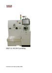
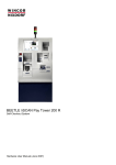
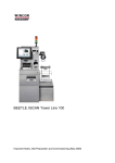
BEETLE POS Tower 100 Scan&Bag
Self-Checkout System
Hardware User Manual (April 2007)
We would like to know
your opinion on this publication.
Please send us a copy of this page
if you have any constructive criticism on:
- the contents
- the layout
- the product.
We would like to thank you in advance
for your comments.
With kind regards,
Wincor Nixdorf International GmbH
RD PD1
Wernerwerkdamm 16
Gebäudegruppe 36
D-13629 Berlin
Fax: +49 30 5017 1075
_________________________________________________________________________________________________________________
Your opinion
Copyright © Wincor Nixdorf International GmbH, 2007
The reproduction, transmission or use of this document or its contents is not permitted
without express authority.
Offenders will be liable for damages.
All rights, including rights created by patent grant or registration of a utility model or design, are reserved.
Delivery subject to availability; technical modifications possible.
Contents
Introduction.................................................................................................................................................................1
Components ...............................................................................................................................................................2
Components Inside .................................................................................................................................................3
Rotating the top module of POS Tower 100 by 180°....................................................................................................6
Maintenance ...........................................................................................................................................................7
ESD (Electrostatic Sensitive Devices) .........................................................................................................................8
Installation and startup................................................................................................................................................9
Before turning on the system...................................................................................................................................9
Setting up the device...............................................................................................................................................9
Connecting the cables...........................................................................................................................................10
Printer TP07 Compact ..............................................................................................................................................12
Pulling out the printer ............................................................................................................................................12
Changing the paper roll .........................................................................................................................................13
Setting the paper roll core diameter....................................................................................................................13
Choosing a paper roll holder..................................................................................................................................14
Inserting the paper roll...........................................................................................................................................15
Removing the paper roll ........................................................................................................................................15
Cash Media Dispenser - Vertical Cash-Out ...............................................................................................................16
Modules and function elements..........................................................................................................................18
Function elements..............................................................................................................................................19
Cash-out cassette ..............................................................................................................................................20
Reject / retract cassette .....................................................................................................................................21
Removing the cassette.......................................................................................................................................22
Transporting the cassette...................................................................................................................................22
Opening the cassette .........................................................................................................................................22
Emptying the reject / retract cassette..................................................................................................................23
Filling the cash-out cassette...............................................................................................................................24
Preparing the banknote bundles.........................................................................................................................24
Inserting banknote bundles ................................................................................................................................25
Possible deformation of banknotes.....................................................................................................................27
Inserting the cassette.........................................................................................................................................29
Closing the cassette...........................................................................................................................................29
Inserting the cassette.........................................................................................................................................30
Cassette initialization .........................................................................................................................................30
Status messages (CMD controller).....................................................................................................................31
Checking the note paths ....................................................................................................................................33
Coin Dispenser .........................................................................................................................................................38
Components..........................................................................................................................................................38
Switching off / pulling out the Coin Dispenser .....................................................................................................39
Slide in / Rotating the Coin Dispenser ................................................................................................................40
Factory Settings ....................................................................................................................................................40
Coin Capacity........................................................................................................................................................41
Low Coin Modes ...................................................................................................................................................41
Alarm Sound .........................................................................................................................................................41
Low Coin Disabled ................................................................................................................................................41
Low Coin Enabled, Even Depletion Off (Dispense by bin or dispense by amount).................................................42
Low Coin Enabled, Even Depletion On (Dispense by amount) ...............................................................................42
Dispense History ...................................................................................................................................................42
In System Programming ........................................................................................................................................42
External Power supply...........................................................................................................................................42
Power Cable .........................................................................................................................................................42
Communications Cable .........................................................................................................................................43
Filling the Coin Dispenser......................................................................................................................................43
Emptying the Coin Dispenser ................................................................................................................................43
Clearing a Coin Jam..............................................................................................................................................45
Maintenance ......................................................................................................................................................45
Trouble Shooting ...............................................................................................................................................46
Specifications........................................................................................................................................................48
Coin Input .................................................................................................................................................................49
Correcting a coin jam ............................................................................................................................................49
CMD V4-Shutter .......................................................................................................................................................51
Introduction ...........................................................................................................................................................51
Function ................................................................................................................................................................52
Cash removal ....................................................................................................................................................52
Error code 28.....................................................................................................................................................52
Single Banknote Validator.........................................................................................................................................53
Function elements and controls .............................................................................................................................54
Validator unit .........................................................................................................................................................54
Cash boxes ...........................................................................................................................................................56
Removing / inserting the cash box .........................................................................................................................57
Opening / closing the cash box..............................................................................................................................58
Emptying the cash box ..........................................................................................................................................59
Description of the banknote path ...........................................................................................................................59
LEDs.....................................................................................................................................................................60
Optical signals.......................................................................................................................................................60
General..............................................................................................................................................................60
Cleaning and maintenance ....................................................................................................................................61
Cleaning card ....................................................................................................................................................61
Validator unit......................................................................................................................................................61
Lower section of the single banknote validator ...................................................................................................63
Transport rollers and transport belts...................................................................................................................64
Autocalibration ......................................................................................................................................................66
BEETLE /M-II............................................................................................................................................................67
Front view..........................................................................................................................................................68
Inside view ............................................................................................................................................................68
Back view..............................................................................................................................................................69
Central USB Special Electronics Module...................................................................................................................70
Functions of the special electronics .......................................................................................................................71
Control Panel ........................................................................................................................................................72
Power Supply Unit ....................................................................................................................................................73
Views ....................................................................................................................................................................74
Front view..........................................................................................................................................................74
Rear view ..........................................................................................................................................................75
Description............................................................................................................................................................75
Safety functions .................................................................................................................................................75
Proximity Sensor.......................................................................................................................................................77
Introduction ...........................................................................................................................................................77
Function ................................................................................................................................................................77
Waiter Lock ..............................................................................................................................................................78
Scanner (Scale optional)...........................................................................................................................................79
Scanner Maintenance ........................................................................................................................................79
Scanner Usage ..................................................................................................................................................79
Scanning Items..................................................................................................................................................79
Proper Scanning Technique...............................................................................................................................79
Security Scale...........................................................................................................................................................80
Adjusting the Security Scale Module ..................................................................................................................80
Coupon Box..............................................................................................................................................................81
Emptying the Coupon Box .....................................................................................................................................81
UPS (Unbreakable Power Supply - optional) .............................................................................................................82
Appendix ..................................................................................................................................................................83
Changing the Safe Code (LG 39E) ........................................................................................................................83
Generally ...........................................................................................................................................................84
Programming Manager ......................................................................................................................................88
Programming on PC ..........................................................................................................................................92
Manual programming .........................................................................................................................................94
Block Diagram.......................................................................................................................................................96
Environmental Requirements.................................................................................................................................97
Cleaning Instructions.............................................................................................................................................98
Maintenance and Service...................................................................................................................................98
Maintenance for rotating top module ..................................................................................................................98
Approved Cleaning Materials .............................................................................................................................99
Important Notes...................................................................................................................................................100
Note on Laser .....................................................................................................................................................102
Certifications of the manufacturer............................................................................................................................103
Note on Radio Interference Suppression .............................................................................................................103
FCC-Class A Declaration.....................................................................................................................................103
Recycling the BEETLE /iSCAN Scan&Bag ..........................................................................................................104
BEETLE POS Tower 100 Scan&Bag
Hardware User Manual
Introduction
The BEETLE POS Tower 100 Scan&Bag is a terminal where the user handles the purchase by
scanning, bagging and paying the items on his own. In case of problems an attendant is available for
quick support.
The BEETLE POS Tower 100 Scan&Bag is connected to an attendant station. This is a POS system
controlling all connected POS Tower 100 Scan&Bag terminals.
BEETLE POS TOWER 100 Scan&Bag offers the following main functions:
Record function - records items, the customer wants to buy
Control function - secures the recording of all items
Payment function - payment may be effected by banking cards, customer cards and accounts,
coupons, bank notes or coins. Cash return uses bank notes and coins.
1
BEETLE POS Tower 100 Scan&Bag
Hardware User Manual
Components
11
10
9
1
15*
8
2
7
14
6
3
13
5
4
12
16
1
Screen
5
Waiters Lock
9
Coin In
13
Hardtag Detector
2
Receipt
6
Coupon In
10
Note In
14
Bag Holders
3
Scanner / Scale
7
Coin Out
11
Pole Light
15
Pin Pad*
4
Note Output
8
Swipe Card
Reader
12
Security Scale
16
UPS
*The Pin Pad is customer specific, different models and positions are possible
2
BEETLE POS Tower 100 Scan&Bag
Hardware User Manual
Components Inside
At the side of the POS Tower 100 Scan&Bag you find the lock for the front door. Put the key into the
lock, turn it to the right and swing the door upwards.
Have a look on the components on the next page.
3
BEETLE POS Tower 100 Scan&Bag
Hardware User Manual
4
1
7
2
6
8
5
3
1
Coin Dispenser
5
Coupon Box
2
Printer
6
Coin Box
3
Scanner Scale
7
Note Box
4
Coin Recognition
8
BEETLE /M-II
4
BEETLE POS Tower 100 Scan&Bag
Hardware User Manual
Behind the bottom door you find the Media Cash Dispenser (1), the CMD Shutter (2) and the central
power supply unit in the back of the safe (3). You also find optional Hardtag Detector in the safe.
2
1
3
Lock for the safe
5
BEETLE POS Tower 100 Scan&Bag
Hardware User Manual
Rotating the top module of POS Tower 100 by 180°
You can rotate the top module of the POS Tower 100 Scan&Bag including scanner, printer, coin
dispenser etc. by 180°.
Therefore, insert the key into the lock (see arrow) and unlock it.
6
BEETLE POS Tower 100 Scan&Bag
Hardware User Manual
Turn the bag holders (1) down.
Now rotate the top module by 180° using both hands!
2
1
Maintenance
Clean the rotating surface for the top module after 500 rotations or at least once a year. Clean it with
commercially available cleaner.
Dry rotating surface after cleaning!
7
BEETLE POS Tower 100 Scan&Bag
Hardware User Manual
ESD (Electrostatic Sensitive Devices)
Assemblies containing electrostatic sensitive devices (ESD) may be
labeled with this sticker.
When installing an assembly or drive, please follow the guidelines below, which apply to all
electrostatic sensitive devices (ESD):
Make sure you are not carrying a static charge before working with components marked as
ESD by first touching a grounded object (such as a radiator from a hot water heating system).
All tools and devices you use must be free from static charges.
Always unplug the power cord before installing or removing any assemblies.
Always handle assemblies by their edges.
Never touch the terminal pins of the circuits on an assembly.
8
BEETLE POS Tower 100 Scan&Bag
Hardware User Manual
Installation and startup
i
Be certain to follow the safety guidelines on page 100.
Before turning on the system
Unpack the parts and make sure that every item at the packing list is included.
If you find
shipping damage or
discrepancies between the contents of the package and the packing list or
defects,
please inform your vendor or Wincor Nixdorf International GmbH (WN) sales location immediately.
Also provide the packing list and the packing list item and serial numbers for the effected unit. You will
find the serial number on the adhesive label on the underside of the system as shown below.
Wincor Nixdorf
The serial number is located
on the label below the bar code.
BEETLE POS Tower 100
017500 000000
0199900107
WN
100-120V
50/60 Hz
/ 200-240V
5/3 A
Made in Singapore
Setting up the device
Place the BEETLE POS Tower 100 Scan&Bag in a location where the system will not be subject to
extreme environmental conditions. The system should be placed on a level surface. Keep the device
away from vibrations, dust, humidity, heat and strong magnetic fields.
i
For further information please read the “Important Notes, Site Preparation and
Commissioning” manual.
9
BEETLE POS Tower 100 Scan&Bag
Hardware User Manual
Connecting the cables
The cables of the system should be connected in the order described below:
i
Make sure that the cash register system is turned off and the power cord of the system has
been disconnected.
Plug in the data cable and secure it.
Never plug data or electrical supply cables (except for USB) when the system is running.
Connectors with thumb wheels can be secured
by hand.
Connectors with metal screws can be secured
using a screwdriver. Plastic screws should only
be tightened by hand.
RJ12 connectors lock in place when plugged in.
LAN connectors lock in place when plugged in.
10
BEETLE POS Tower 100 Scan&Bag
Hardware User Manual
USB plugs that are not supplied with power do
not latch in place when plugged in, and can be
unplugged with a gentle pull.
USB plugs that are supplied with power lock in
place when plugged in.
TFT plugs lock in place when plugged in.
Mini-DIN plugs lock in place when plugged in.
Check that the cable is correctly connected by
pulling it gently.
You may have to push the plug gently into the
socket before it latches.
11
BEETLE POS Tower 100 Scan&Bag
Hardware User Manual
Printer TP07 Compact
Pulling out the printer
Open the front door as shown on page 3. Pull out the printer by using the handle underneath the
paper outlet (see arrow).
12
BEETLE POS Tower 100 Scan&Bag
Hardware User Manual
Changing the paper roll
Setting the paper roll core diameter
When starting the device or when changing the paper roll diameter check whether the selection switch
for the paper near end adjustment is set to the correct position.
Core diameter
Paper roll diameter180 mm
18 mm
Pos. A1
25 mm
Pos. A2
A
A2
A1
13
BEETLE POS Tower 100 Scan&Bag
Hardware User Manual
Choosing a paper roll holder
Choose the roll holder which fits to the paper roll core
Holder for 18 mm core diameter (identifier 1)
Holder for 25 mm core diameter (identifier 2)
14
BEETLE POS Tower 100 Scan&Bag
Hardware User Manual
Inserting the paper roll
Push the paper roll holder into the paper roll core. Insert the paper from behind into the printer as
shown in the illustration. Mind the unrolling direction of the paper.
Pos.B
Insert the black mark sensor (top left, top right, bottom left, bottom right) when using paper with black
marks.
For correct paper feed or paper transport the front edge of the paper has to be straight and at right
angles.
We therefore recommend to cut the paper with scissors.
Take the front edge of the paper over the upper
axle and feed it into the paper support (see arrow).
Keep pushing the paper into the paper support until
it is retracted automatically, the paper is cut off and
the printed receipt is output via the presenter.
See also the sticker on the printer.
Remove the receipt that was cut off before.
Removing the paper roll
Cut off the paper at the paper support. Lift the paper roll out of the printer with the paper roll holder
upwards. Use the LINE FEED button to remove the remaining paper.
15
BEETLE POS Tower 100 Scan&Bag
Hardware User Manual
Cash Media Dispenser - Vertical Cash-Out
Switch off the device. Insert the key into the lock, turn it to the right and open the bottom door of the
POS Tower 100 Scan&Bag.
Now enter the code number of the safe in the data field (1), turn the knob (2) to the right and open the
door. The display BA63 is only installed for calibration of the security scale.
2
1
16
BEETLE POS Tower 100 Scan&Bag
Hardware User Manual
Seize the Media Dispenser (green handle – see arrow) and pull it out completely.
17
BEETLE POS Tower 100 Scan&Bag
Hardware User Manual
Modules and function elements
This is not part of POS Tower
Line 100 Scan&Bag
1
2
3
4
5
6
7
8
9
10
1
Stacker and output transport facility (SAT)
Not in POS Tower Line 100 Scan&Bag
6
Function key
2
CMD controller
7
Cash-out cassette 1
3
Reject / retract cassette
8
Cash-out cassette 2
4
Status display
9
Cash-out cassette 3
5
Release lever
10
Cash-out cassette 4 (not available)
18
BEETLE POS Tower 100 Scan&Bag
Hardware User Manual
Function elements
1
2
1
Status display (two 7-segment displays, first digit on the top)
2
Function key
19
BEETLE POS Tower 100 Scan&Bag
Hardware User Manual
Cash-out cassette
15
8
1
9
2
10
3
11
4
12
5
13
6
14
7
16
1
Pull-back handle
9
Refill notes
2
Banknote rail
10
Inset for setting the banknote height
3
Slide for low cash sensor (optional)
11
Latching button
4
Pressure carriage
12
Free space for validity identification
5
Tamper indicator blue/green
13
Free space for cassette label
6
Sealing device
14
Cassette handle
7
Locking / unlocking lever (optional
lock
15
Dispensing side
8
Cassette lid
16
Side of cassette handle
20
BEETLE POS Tower 100 Scan&Bag
Hardware User Manual
Reject / retract cassette
1
2
3
4
5
6
7
1
Cassette lid
5
Tamper indicator blue/green
2
Retract compartment lever
6
Cassette handle
3
Retract compartment
7
Locking / unlocking lever (optional lock)
4
Reject compartment
21
BEETLE POS Tower 100 Scan&Bag
Hardware User Manual
Removing the cassette
Before cassettes can be removed the BEETLE POS Tower 100 Scan&Bag Terminal
should be shut down.
To remove the cassettes from the CMD-V4:
Press the green releasing tab on the right
side of the cassette (1).
The released cassette is automatically
pushed out of the dispenser by several
centimeters.
Raise the cassette handle (2) and pull the
cassette out of the CMD-V4 by the handle
(2). While pulling the cassette, support it
from underneath with your free hand.
Transporting the cassette
Make sure that the cassette(s) are not damaged or dropped during transport.
Opening the cassette
The procedure for opening cash-out cassettes and reject/retract cassettes is the same.
Remove any seal (1) on a cassette with a
sealable lock. Insert the cassette key into
the cassette lock, turn the key to the right as
far as possible (2) and lift the cassette lid in
the direction of the arrow (3).
1
22
BEETLE POS Tower 100 Scan&Bag
Hardware User Manual
Emptying the reject / retract cassette
The reject / retract cassette is divided into a reject and a retract compartment.
Banknotes which are not removed by the customer after the cash dispensing procedure are returned
to the retract compartment. Cash which has been incorrectly dispensed or which was dispensed for
test purposes is stored in the reject compartment.
Remove and open the cassette (see section "Opening the cassette").
Remove the banknotes from the
cassette's reject compartment.
To empty the retract compartment, push
the green lever in the direction indicated
as far as possible and hold it down. You
can remove the cash from the retract
compartment with your other hand (2).
23
BEETLE POS Tower 100 Scan&Bag
Hardware User Manual
Filling the cash-out cassette
Filling the cash-out cassettes includes the following steps:
Preparing the cash-out cassette
Preparing the banknote bundles
Inserting banknote bundles
In general, all banknotes complying with the requirements of the national banks are
suitable for use in the cash-out cassette.
To ensure error-free dispensing, fill the cash-out cassette only with intact and carefully prepared
banknote bundles which only contain notes of the same value.
Preparing the banknote bundles
Check the banknotes for damages before you put them into the cash-out cassettes.
Sort out the damaged banknotes and/or remove clips, needles or other foreign objects
The following banknotes should be rejected: torn, glued, folded, creased, stapled or
clipped banknotes.
If you use new bank notes / bank note
bundles, you must separate the bank
notes at the cutting edges. Carefully fan
the bank note bundles and bend and
twist them repeatedly in various
directions.
24
BEETLE POS Tower 100 Scan&Bag
Hardware User Manual
Inserting banknote bundles
Also follow the instructions for filling the dispenser cassette on the inside of the
cassette cover.
General instructions for filling the cassette
Remove any existing bank wrappers made of
paper, plastic or rubber before inserting the
banknote bundle.
You should always insert the banknote
bundles into the cash-out cassette so that the
silver stripes or other raised embossing of the
individual bundles are alternately pointing to
the left and to the right.
25
BEETLE POS Tower 100 Scan&Bag
Hardware User Manual
New and used banknote bundles
If you use new and used banknote bundles in
one cassette, always insert the bundles with the
used banknotes into the cassette first.
Then insert the bundles with the new banknotes
after you separated them at the cut edges (see
the section "Preparing banknote bundles").
Deformed banknote bundles
Insert banknote bundles which were deformed
by packaging (bands with paper, plastic or
elastic bands) as follows:
Split the banknote bundle and turn the first half
of the bundle so that the bent side is pointing
towards the pressure carriage.
Insert the two bundle halves into the cassette
as shown in this picture.
Please do not use any extremely deformed
banknotes.
Always insert banknote bundles which are bent
horizontally into the cash-out cassette in such a
way that the side of the bundle bulging out is
pointing towards the pressure carriage.
Take the banknote bundles from the packaging,
fan the banknotes and put them into the
cassette as shown in the picture.
26
BEETLE POS Tower 100 Scan&Bag
Hardware User Manual
Press the green latching button on the
pressure carriage and push the carriage
against the banknotes far enough to
prevent them from falling over. The
inserted banknotes do not need to be
pressed together.
Close the cash-out cassette and re-insert it (see section "Inserting the cassette").
Possible deformation of banknotes
Type A:
Deformation near the hologram
Type B:
S shape
Type C:
Wavy shape
The following illustrations show in which order the deformed banknotes have to be inserted.
Note that the deformed corners of the banknotes must always point to the side from which the notes
are dispensed. The bulging side always has to point to the pressure carriage / cassette handle.
Type A:
Turn the bundle so that the deformed corner
of the banknote is pointing not to the
pressure carriage.
27
BEETLE POS Tower 100 Scan&Bag
Hardware User Manual
Type B:
Bundles whose S shape is pronounced and
exceeds 5 mm should not be used.
If no other banknote bundles are available,
the entire bundle needs to be formed to a U
shape as to be fit for use. Insert these
bundles so that the deformed corners are
pointing at the bottom to the pressure
carriage.
Type C:
If the bundle has a wavy shape as a result
from having been tied, turn it so that the
deformed corners are pointing to the
pressure carriage.
28
BEETLE POS Tower 100 Scan&Bag
Hardware User Manual
Inserting the cassette
The procedure for inserting cash-out cassettes and reject/retract cassettes is the
same.
Closing the cassette
If the cassette has a lock, close the
cassette lid (1) and turn the key (2) to
the left as far as possible. Pull the key
from the cassette lock.
2
29
BEETLE POS Tower 100 Scan&Bag
Hardware User Manual
Inserting the cassette
Normally the tamper indicator (1) is 'green'. If the indicator is blue, the cassette has been
tampered with or has been forced open (tamper indicator).
To switch the tamper indicator to green, proceed as follows:
Unlock the cassette using the key and turn the locking/unlocking lever to the left. Open the lid
(see section "Opening the cassette").
Close the cassette lid and turn the locking / unlocking lever to the left as far as possible. Lock
the cassette using the key (see section "Closing the cassette").
Push the cassette back into the CMD-V4 in one
uninterrupted motion until it audibly latches into
place. Wait for the single signal tone confirming the
correct pressure build-up in the cassette.
1
If a triple signal tone sounds instead of a single tone, remove the cassette and check the
contents of the cash-out cassette (see the instructions in the section "Filling the cash-out
cassette"). Then try again to insert the cassette.
The acoustic warning (triple signal tone) is accompanied by a message on the status display of the
controller (ZAC).
Example:
- Cash-out cassette 1
Cassette initialization
The initialization of the cassettes is necessary in case of new types of banknotes or cassettes. With
the initialization the system will be informed about the cassette number, the currency and the
denomination of the banknotes. If necessary, you can enter more parameters.
Please observe the product-specific and bank requirements concerning change of standard or
individual changing of cassettes. Please obtain this information from the bank's administration.
30
BEETLE POS Tower 100 Scan&Bag
Hardware User Manual
Status messages (CMD controller)
The CMD's controller status messages are listed in the following table. The status messages, their
meanings and the remedies you must employ are explained so that you can eliminate CMD-V4
problems.
If, contrary to expectations, you are unable to fix the problem, you should contact the Service.
The two-digit codes indicate the following error messages:
No.
off
Meaning
No power supply
Start-up (after RESET or
electronics self-test)
Remedy
Switch on the device.
Wait until start-up is complete.
Controller OK
No error
-
Software faulty
Switch the device off and on.
Communication problem
with Chip Card controller
Perform a reset using the function button. If error message
'05' does not disappear, contact customer service.
Communication problem
with Chip Card / or wrong
Chip Card inserted (Chip
Card number not '2260PR').
Missing software
(download)
Perform a reset using the function button. If error message
'06' does not disappear, contact customer service.
Perform a reset using the function button. If error message
'11' does not disappear, contact customer service.
Safety switch open
Insert the CMD-V4.
Device disable present
Remove banknote bundles from the CMD-V4.
Reset the device lock using the product-specific software (see
chapter "Basic Operation", section "Calling the productspecific software").
Insert and log in cassette (reject and cash-out cassette
required).
CMD-V4 minimum
configuration is missing
Belt drive of clamp
defective
Banknotes jammed during
dispensing
Check the cash paths in the stacker, in the area of the stacker
wheels and in the dispenser modules (see section "Checking
the cash paths").
Move the CMD-V4 in the safe to the cash-out position and
wait for the system to boot.
If error message '18' does not disappear, contact customer
service.
Clamp transport defective / Check the cash paths in the output transport (see section
"Checking the cash paths").
blocked
Move the CMD-V4 in the safe to the cash-out position and
wait for the system to boot.
31
BEETLE POS Tower 100 Scan&Bag
Single reject switch
(MA2/SM1) defective /
blocked
Hardware User Manual
Check the cash paths in the output transport (see section
"Checking the cash paths").
Move the CMD-V4 in the safe to the cash-out position and
wait for the system to boot.
Faulty measuring station
(DDU)
Clear the cash paths (see section "Checking the cash paths").
Move the CMD-V4 in the safe to the cash-out position and
wait for the system to boot. If error message '22' does not
disappear, perform a reset using the function button. If you do
this three times without success, contact customer service.
Routing disk (DCM2/SM3) If you cannot pull out CMD-V4, perform a reset using the
function button. If error message '23' does not disappear,
defective / blocking
contact customer service. If you can pull out the CMD-V4,
check the cash paths in the stacker and output transport (see
section "Checking the cash paths").
Move the CMD-V4 in the safe to the cash-out position and
wait for the system to boot.
Reject/retract drive (MA6) Empty the reject compartment of the reject / retract cassette
(see section "Emptying the reject / retract cassette").
defective / blocked (lifting
Check the cash paths in the stacker (see section "Checking
magnet)
the cash paths").
Move the CMD-V4 in the safe to the cash-out position and
wait for the system to boot.
Dispensing drive (DCM 1) Clear the cash paths (see section "Checking the cash paths").
Move the CMD-V4 in the safe to the cash-out position and
defective / blocked
wait for the system to boot.
Stacker wheel drive (SM 9) Check the cash paths in the stacker and output transport (see
section "Checking the cash paths").
defect / blocked
Move the CMD-V4 in the safe to the cash-out position and
wait for the system to boot.
Shutter error
Check the shutter.
Perform a reset using the function button.
Photo sensor amplifier
faulty or photo sensor
initialization unsuccessful.
Cash-out photo sensor
covered (manipulation)
X
Check the cash paths in the output transport (see section
"Checking the cash paths").
Perform a reset using the function button.
Too many problems during Bundle rejects can be caused by extremely deformed
dispensing from cassette x banknotes or banknotes that are extracted in an uncontrolled
(x = 1 – 6)
way or by problems with the photo sensors.
This error can be ignored the first time it occurs (warning). If
the error keeps occurring, please proceed as follows:
- Remove the cassette from dispenser module 'x' and check
-
-
contents of banknotes:
Is the correct banknote type in the cassette? Are the front
banknotes deformed on one side? Is the pressure against the front
banknotes even on the right and on the left side?
With the cassette removed check the dispensing area in the
dispenser module for stuck banknote scraps (see section
"Checking the cash paths").
Check the transport path from cassette 'x' to the clamp for jammed
banknotes/scraps (see section "Checking the cash paths").
Check the connectors at the CMD controller.
Determine the reference value (see section "Determining the
reference value").
32
BEETLE POS Tower 100 Scan&Bag
No.
X
X
X
X
X
Meaning
Banknotes cannot be
dispensed or incorrect
pressure on notes in new
cassette
(x = 1 - 6)
Too many bad banknotes
(x = 1 - 6)
Hardware User Manual
Remedy
Check the contents of cash-out cassette 'x' for position
and quality of banknotes (see sections "Preparing
banknote bundles" and "Inserting the banknote bundles").
Check the dispensing area for stuck banknotes (see
section "Checking the cash paths").
Place the cassette in position again and check the
function with a test dispense (see section "Function
test").
Check the contents of cassette 'x'.
Cassette defective
(x = 1 - 6)
Replace the defective cassette with a new initialized
cassette.
Banknote measuring station
(DDU) not ready
Check whether there is a banknote jam in the upper
dispensing unit. Are the cables connected? If the error
message does not disappear, contact customer service.
Dispensing sensor PSDx dirty
or pressure sensor faulty
(x = 1 - 6)
Cassette empty sensor PSEx
dirty
(x = 1 - 6)
Photo sensor PS 1 dirty
Photo sensor PS 18 dirty
Photo sensor PS 2 dirty
Photo sensor PS 27 dirty
Photo sensor PS 28 dirty
Checking the note paths
Before checking the banknote paths, you should perform the following steps:
Activate the product-specific software
Open the safe
Holding the green release lever, pull out the CMD-V4 as far as possible
If the release lever jams, you must check the current position of the clamp. If possible,
push the clamp carefully back to its home position. Perform a reset using the function
button. Now check whether you can remove the CMD-V4.
33
BEETLE POS Tower 100 Scan&Bag
Hardware User Manual
Checking the dispensing areas
In the dispenser modules the vertical transport (at the rear) and the dispensing area
(inside the device) must be checked.
The dispensing areas can only be checked when the cassettes have been removed
from the dispenser modules (see section "Removing the cassette").
Check the dispensing area of each dispensing module for
banknotes and if necessary remove the notes (see arrow).
Re-insert all cassettes which were removed (see section "Inserting the cassette").
Log on the cassettes using the product-specific software (see chapter "Basic Operation",
section "Calling the product-specific software").
Checking the stacker and output transport
Do not try to open the clamp by force; you could damage it.
Stacker wheel area
Check the area around the vertical transport and if
necessary remove any notes.
34
BEETLE POS Tower 100 Scan&Bag
Hardware User Manual
Single reject area
The function of the single reject depends on the individual configuration.
Press the green release levers (1)
outwards and pull the flap (2) forwards.
Check the area and if necessary remove
the banknotes (3).
35
BEETLE POS Tower 100 Scan&Bag
Hardware User Manual
Gear tracks of the stacker and output transport
If the clamp has come to a standstill at a
position outside the stacking position, you
may need to check and clean the gear
tracks (1).
1
Check the photosensors in the shutter area.
After checking the cash paths, proceed as follows:
After checking the cash paths push the CMD-V4 by the green release lever back into the safe
as far as possible.
Close the safe door
Function test
Press the function pushbutton on the CMD-V4 controller to start tests and to reset the CMD-V4. To
start a test function, the CMD-V4 must be in normal operating mode. '00' or '14' is then shown on the
status display.
When you press and hold the function key, '00', '1', '2', '3', '4' and '5' are shown on the status display.
What these numbers mean is described in the following table. To start a particular sequence, release
the key when the status display shows the relevant value.
The functions described in the following sections can be performed only when the safety
switch is closed (i.e. the CMD-V4 is in cash-out position). Functions '2' and '3' may be started
only from normal operation (display '00' or '14') or when all transport paths are guaranteed to
be clear.
36
BEETLE POS Tower 100 Scan&Bag
Display
Function
Normal
operation
Hardware User Manual
Function description
-
RESET
The CMD-V4 is powered up while '—' is displayed on the
status indicator (for approx. 10 seconds). If an error is
detected which prevents or endangers the operability of the
CMD-V4 (soiled photosensors), the relevant error or a
warning is displayed on the status display.
This test function is identical to the power-up test when the
CMD-V4 is pushed into the dispensing position (closing the
safety switch).
Overall test In this test all mechanical CMD-V4 components are operated
one after the other. If an error is detected, it is displayed on
+ RESET
the status display. The lifting magnets for the single reject
switch and retaining shafts and the electromagnetic clutch
can only be subjected to a visual function check in this case.
If no errors are detected during the test, a RESET is then
carried out.
Test
dispensing
+ RESET
Display
firmware
version
With this test the cash paths and the dispensing function of all
inserted and filled cassettes are checked: First a banknote is
extracted from the top cassette and transported via the single
reject switch to the reject compartment. Then one banknote is
extracted from each cassette, transported by the clamp to the
waiting position (the shutter remains closed) and then to the
reject compartment. If an error occurs, it is displayed on the
status display. If no errors are detected during the function, a
RESET is then carried out.
The version number is displayed in alternating mode.
Example:
In the case of the module label
$MOD$ 011214 1000 CMD_V4_0.BIN
version number 1000 of the first release on December 14,
2001 is displayed as follows:
10 for 2 seconds (basic release / upgrade release)
00 for 1 second
elimination))
Statistics
counter
reset
(upgrade (expansion) / update (error
After nine attempts, the device returns to normal mode.
The resettable counters are reset to 0 and the current date of
the real time clock is saved.
37
BEETLE POS Tower 100 Scan&Bag
Hardware User Manual
Coin Dispenser
Components
The figure identifies the major parts of the Coin Dispenser.
7
6
1
2
3
4
5
1
DC Power Jack
2
ON/OFF Switch
3
Status lights
5
RS 232 Port
6
Coin Hopper
7
Hopper Cover
4
USB Port
Coin hoppers
Contains the coin inventory. Coin hoppers are available in models that support
several types of coins.
Hopper Covers
A hinged hopper cover encloses the hopper bins. Prevents unwanted coins and
debris from entering the hopper during filling and use. Allows a hopper to be tilted
while filled with inventory.
Communication ports
USB or RS-232 serial interface connecting to the point of sale device or terminal.
Status lights
Green (constant)
Red (constant)
Red (blinking)
Yellow (blinking)
Power LED. Reports when the device is on and ready.
Warning LED. Reports a machine error.
Warning LED. There are one or more bins with low coin status.
Communication LED. Flashes briefly when valid RS-232 or data flow
communications are passed to or from the host.
DC power jack
Receptacle into which the power cable is inserted.
Power switch
Powers the coin dispenser on and off.
38
BEETLE POS Tower 100 Scan&Bag
Hardware User Manual
Switching off / pulling out the Coin Dispenser
Unlock the front door and swing it up. Put the key to the lock and turn it to the left to unlock the coin
dispenser (1). Seize the green handle in the middle (2) and pull the coin dispenser out completely.
2
1
Switch off the coin dispenser (Position 0).
39
BEETLE POS Tower 100 Scan&Bag
Hardware User Manual
Slide in / Rotating the Coin Dispenser
Press the green locking and slide in the coin dispenser.
Avoid squeezing your hand!
1
While lifting up the locking mechanism (1) you can turn the coin dispenser 90° to the right.
Factory Settings
The coin dispenser is configured at the factory according to the customer's specific requests.
The following standard options are programmed, unless otherwise specified:
"Even Depletion" of coins (versus "minimum dispense")
USB HID device
Low coin alarm enabled
Low coin sound enabled
The procedures to change these options are described in the Service Guide. Contact your service
provider for assistance.
40
BEETLE POS Tower 100 Scan&Bag
Hardware User Manual
Coin Capacity
The coin dispenser US Standard 3 bin dispenser holds approximately €200 in coins.
The high capacity of the coin dispenser assures more transactions between refills. A single US
Standard bin configuration can last between 4-5 hours in a high volume sales setting.
The time between fills will vary, depending on your particular environment. You can perform
your own calculations by using the following information:
Assume an average transaction dispenses 50 cents
Divide the amount of the coin inventory (in this example, a US Standard 3 bin coin dispenser
with €200 in coins) by 50 cents, which yields over 400 transactions between fillings.
Determine how many transactions per hour are conducted in your operation (for this example,
we use 70 transactions)
Divide the 400 transactions per filling by 70 transactions per hour, which yields 5.7 hours
This example assumes the even depletion option, which is the factory-standard setting.
Low Coin Modes
Your service technician can set your coin dispenser for any of the following options with the Configure
and Test Application, as described in the coin dispenser Service Guide.
As bins start reaching low coin status they will go through cycles of high and low coin. This occurs as
coins mechanically move on and off the low coin sensor plates. Eventually, low coin will go low and
stay low. A low coin condition is reported by the “low coin status” at all times, no mater how the
machine is configured.
Alarm Sound
If the low coin alarm is enabled, whenever the dispenser is in a low coin condition the speaker will
sound in a pulsing rhythm.
Low Coin Disabled
If low coin is disabled, the coin dispenser will report low coin as each bin goes into a low coin
condition. The coin dispenser will never take action on this condition and it is possible to try to
dispense from an empty bin.
On low coin conditions the status is reported in the machine status byte. The POS system may take
advantage of the low coin report from the dispenser to create a prompt for the user.
41
BEETLE POS Tower 100 Scan&Bag
Hardware User Manual
Low Coin Enabled, Even Depletion Off (Dispense by bin or dispense by
amount)
When any bin of coin drops below a certain level, the low coin alarm will be set (the alarm will sound
only if it is enabled). A low coin condition sets a number of allowable coin dispenses (20 coin
dispenses is the default setting. This number is configurable) from the low coin bin before the
dispenser stops dispensing. Should the low coin condition go away because of the stirring action of
the hopper, the allowable dispenses for that bin are reset. A machine that stops dispensing because it
has exceeded allowable dispenses after low coin will have an inventory of 10 to 30 coins in the bin.
To silence the alarm, turn the power switch off. Refill the coin dispenser and then turn the power back
on.
If the coin dispenser is powered up with any of the bins in a low coin condition, it will not dispense
coins until power is cycled with all bins above the low coin level.
Low Coin Enabled, Even Depletion On (Dispense by amount)
When the first bin reports a low coin condition, the red LED will start to flash and the alarm will sound
(if enabled). The dispenser will continue to operate until the coin inventory is insufficient to satisfy the
‘dispense below value.’ After this has been reached the red LED will turn solid, dispensing will be
disabled and the alarm will change to a constant tone (if enabled).
On low coin conditions the status is reported in the machine status byte. The POS system may take
advantage of the low coin report from the dispenser to create a prompt for the user.
Dispense History
A history of coins dispensed is stored in volatile memory. A separate count is stored for each bin.
Cycling power or issuing a ‘clear history’ command will clear history.
The POS system may request history in one of two ways. Coins used from each bin may be reported
after each dispense or reported as accumulated from the last reset. The POS system must manage
this information.
In System Programming
Firmware upgrades can be flashed directly through the RS-232 or USB port with use of a Telequip
upgrade utility.
External Power supply
The Coin dispenser coin dispenser is supplied with a UL listed 24V, 40W external switch mode power
supply. Only UL listed supplies with similar ratings may be used to power the Coin dispenser.
Power Cable
The cable that connects the coin dispenser to the source of electrical power is detachable, and
available in several terminations to match local power receptacles.
42
BEETLE POS Tower 100 Scan&Bag
Hardware User Manual
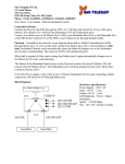
Communications Cable
RS- 232 -- A standard RS-232 serial cable is used to connect the coin dispenser to the point of sale
(POS) device. The cable end that plugs into the coin dispenser is terminated with an RJ-45
connector. The other end of the cable is typically fitted with a DB-9 female connector; however, other
connectors may be requested when placing an order.
USB -- A USB 1.1 Standard A to B cable is used to connect the coin dispenser to the point of sale
(POS) device or teller system.
Filling the Coin Dispenser
Unlatch and open the hopper cover to the denomination you want to fill. Load coin and close the
hopper cover. Move on to the next denomination. Power on the dispenser when filling is done.
Emptying the Coin Dispenser
Start on page 39. Lift up the green bar on the left side of the dispenser (1) and rotate it to the left
by 90°.
Avoid squeezing your hand!
1
43
BEETLE POS Tower 100 Scan&Bag
Hardware User Manual
Unlatch and open the hopper cover to the denomination you want to empty.
Position a container to the side of the hopper being emptied. Hold the hopper firmly and rotate about
the hinge so coin fall into the container.
Rotate hopper back to starting position. There may be several coins remaining in the hopper, which
may be cleared by issuing the audit dump command. Care should be taken to keep fingers clear of the
hinged chassis panels when dumping coins.
44
BEETLE POS Tower 100 Scan&Bag
Hardware User Manual
Clearing a Coin Jam
Occasionally there may be a coin jam that cannot be resolved by the auto reversing of the coin
hopper. There are two methods to correct a jam.
The majority of jams can be cleared by manually rotating the hopper rotor. To
accomplish this, first issue the fault by hopper command to query the dispenser
and identify which hopper is jammed. Then power down the unit. Tilt the jammed
hopper back to reveal the mechanical screw on the side of the hopper base.
Use a Phillips screwdriver and rotate the screw clockwise (oriented so screw is
facing you and the coin ejection side of the hopper is to your right) until the jammed
coin moves past the hopper ejector pin. Do not apply excessive force to the plastic
screw head or it will strip. See section below for jams that cannot be cleared by
this method. Care should be taken to keep fingers clear of the hinged chassis
panels when rotating the hoppers.
If the mechanical screw is not easily turned, the hopper must be disassembled to
free the jam. Once the jammed hopper has been identified and the dispenser is
powered down, open the hopper cover and dump the coin inventory.
Disconnect the 2 low coin terminals on the back of the hopper bin. Facing the coin
ejection side of the hopper, rotate hopper bin counter clockwise and remove. Pull
rotor straight up to remove. Remove the jammed coin and reinsert rotor. Place
hopper bin into position and rotate clockwise until it snaps into position. Reattach
the 2 low coin terminals.
Maintenance
The coin dispenser is designed to be low maintenance. It is important to keep the
coin dispenser clean. Use only a soft, damp cloth to remove surface dirt.
The unit does NOT need to be oiled. Using oil, detergents or petroleum-based
cleaning compounds can adversely affect the reliability of the coin dispenser.
45
BEETLE POS Tower 100 Scan&Bag
Hardware User Manual
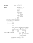
Trouble Shooting
Start
Does the CoinXpress
have a green light on?
NO
Check that the power cord is
connected to the CoinXpress, and
the other end is connected to the
outlet. If the CoinXpress has a
power switch make sure it is on.
YES
Check the USB or
serial interface cable
for damage
Does the CoinXpress
have a green light on?
YES
NO
Is the interface cable
damaged
NO
Verify that the interface
cable is connected to
the Coin Xpress and
the POS system.
Contact Telequip
customer service
YES
Contact Telequip for a
replacement cable.
Use your POS system
to issue a dispense
while viewing the
yellow light on the
CoinXpress. Try this
dispense 2 times.
Did the CoinXpress
dispense coins?
YES
YES
Did the yellow light
flash when you tried to
dispense coins?
NO
Go to Flowchart 2
NO
Go to Flowchart 3
Contact Telequip
customer service.
46
BEETLE POS Tower 100 Scan&Bag
Hardware User Manual
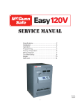
CoinXpress Troubleshoot Flowchart 2
If the CoinXpress dispenses coins start on this
page, otherwise start on page 1
Start
Did the CoinXpress
give correct change?
YES
Finish - CoinXpress
is functioning
You may have a
mechanical jam. This
can be cleared with a
simple procedure.
NO
Empty the coins from
the CoinXpress bins by
tilting the hoppers.
Please refer to section
6 in the manual. Follow
the procedure for
"Clearing a coin jam".
Check the hoppers for
any debris or foreign
objects that could
cause a jam.
NO
Check the few coins
that remain in the
hoppers. You should
be able to move every
coin freely with your
fingertip
Do all the coins
move freely?
YES
Were you able to
clear the jam?
NO
Contact Telequip
Wincor
Contact
Nixdorf service
Customer
YES
Fill the CoinXpress.
Verify PC/POS
settings. Shut down
POS and CoinXpress,
restart and re-test.
47
BEETLE POS Tower 100 Scan&Bag
Hardware User Manual
Specifications
Size:
13 1/2” W x 9” H x 14-1/4” L
Weight:
21 lbs. – 6 bin without coin
65 lbs. - 6 bin with coin
Power:
Power
Consumption:
Power Cord:
Communication
Cable:
24 Volt DC, 2 Amps max.
120 to 240 VAC, 50 or 60 Hz 24V external switch
mode power supply
40W
Detachable power cords with different terminations
to match local power receptacles, and in different
lengths, are available.
Cables with various serial cable terminations and
in different lengths are available.
Operating Temp.
Range:
0 - 40C
Humidity range:
+0 to 80% RH and non-condensing
Certifications:
CE, UL, CUL, FCC
48
BEETLE POS Tower 100 Scan&Bag
Hardware User Manual
Coin Input
Correcting a coin jam
Unlock the front door and swing it up. The coin input is located beside the bank-note input.
Grab the coin input (1) and pull it out completely.
Coin Input
1
49
BEETLE POS Tower 100 Scan&Bag
Hardware User Manual
Correct the coin jam by pressing the mechanism (1) so often until the coin falls into the box.
If this doesn´t work, press on the button (1) and open the coin input. You can remove the coin. Close it
only by pressing the button (2). Otherwise it is possible to damage the coin input module.
1
2
50
BEETLE POS Tower 100 Scan&Bag
Hardware User Manual
CMD V4-Shutter
The CMD V4-Shutter is located in the bottom door.
Introduction
The shutter locks the cash output tray of the cash media dispenser (CMD-V4). It includes the following
assemblies: Drive mechanism with stepper motor, gears, locking mechanism, and two hybrid
photosensors (GL 10 and GL 11) for monitoring the position of the shutter
1 photosensor (LS 28) for providing a cash bundle for output
1 photosensor (LS 27) for monitoring removal of cash
1 Interface board for controlling the shutter
51
BEETLE POS Tower 100 Scan&Bag
Hardware User Manual
Function
The shutter is controlled via the firmware of the CMD-V4 controller and is initiated by the application
software.
Shutter and drive mechanism are directly connected. The rotation of a cam disk makes the shutter
open and close. The stepper motor has low motive force so there is no risk of injury when the shutter
is closed.
The shutter is locked automatically when it is completely closed.
Cash removal
If the application sends an order to dispense cash, the shutter is first opened completely via the
firmware. After the banknotes have been transported into the position where they can be removed, the
shutter is partly closed depending on the thickness of the banknote bundle. The thickness of the
bundle is detected by the thickness measuring unit in the CMD-V4. The value that is identified is used
to control the drive motor for a limited time.
When the cash has been removed the shutter is first opened completely via the firmware and the drive
belts in the transport gripper are briefly moved backward. Then the shutter is closed completely and
locked unless this is prevented by external influences.
Error code 28
If the shutter does not close within approx. 1 second, the firmware turns the motor off, generates an
error code (error code 28 displayed on the CMD-V4 controller) and reports the error to the application.
Error code 29 (protection against tampering)
Error code 29 is displayed if photosensor LS 27 is covered when the shutter is closed. The firmware
tries to close the shutter anyway. The motor is turned off if that does not succeed within approx. 1
second.
52
BEETLE POS Tower 100 Scan&Bag
Hardware User Manual
Single Banknote Validator
The single banknote validator is a component that is used to implement a payment function with
banknotes.
Payments are made by inserting individual banknotes in the banknote input slot.
The banknote is centered automatically, tested in the validator unit and, if it tests positive, is sorted
and conveyed by the transport unit to a cash box, where they are stored. Alternatively, if the test is not
positive, they are returned to the output tray.
Unlock the front door and swing it up. The banknote validator (1) is located beside the coin machine.
Unlock the Note Box by turning the key to the left (2). Remove the box forward to empty it.
1
2
53
BEETLE POS Tower 100 Scan&Bag
Hardware User Manual
Function elements and controls
1
8
2
3
7
4
5
6
1
2
3
4
Validator unit
Release lever of validator unit
Banknote input slot
Release lever of transport unit
5
6
7
8
Box handle
Cash box
Emergency release of validator unit
Combined power and data interface
Validator unit
1
2
3
1 Faceplate
2 Ready indicators
3 Release lever of transport unit
54
BEETLE POS Tower 100 Scan&Bag
Hardware User Manual
1
1 USB port
2 DIP switch
3 Red status LED
2
3 4
5
4 Green status LED
5 Faceplate connector
55
BEETLE POS Tower 100 Scan&Bag
Hardware User Manual
Cash boxes
The cash boxes serve to store inserted banknotes.
There are two different cash boxes depending on the version used. The cash boxes differ in the
material they are made of and their size.
Material
Plastic:
Steel:
Capacity
500 banknotes
900 banknotes
Cash box for 500 banknotes
1
4
5
2
3
6
1 Note input
2 Guide bolts
3 Box handle
4 Box lock
5 Box lid
6 Guide bolts
Cash box for 900 banknotes
1
4
5
2
6
3
1 Note input
2 Guide bolts
3 Box handle
4 Box lock
5 Box lid
6 Guide bolts
56
BEETLE POS Tower 100 Scan&Bag
Hardware User Manual
Removing / inserting the cash box
Removing and inserting the cash box is shown for a 900-note cash box as an example.
The procedure is the same for 500-note cash boxes.
Open the device and pull out the single banknote validator (see chapter "Basic Operation", section "
Opening / closing the device").
Removing it
Insert the key in the lock (1) and turn it as far as
possible in the direction of the arrow (1). Pull
the box out of the device by the handle (2) in
the direction shown by the arrow. Support the
box with one hand.
Inserting it
Holding the box by the handle (1) push it in the
single banknote validator in the direction shown
by the arrow (2). Make sure that the guide bolts
(at left and right on the box) are positioned
correctly in the respective mountings in the
housing. Push the box in as far as possible.
1
57
BEETLE POS Tower 100 Scan&Bag
Hardware User Manual
Insert the key in the lock (1) and turn it as far as
possible in the direction of the arrow (1) and
pull the key from the lock.
Push the single banknote validator in the device as far as possible and close the device (see chapter
"Basic Operation", section " Opening / closing the device").
Opening / closing the cash box
Opening and closing the cash box is shown for a 500-note cash box as an example. The
procedure is the same for 900-note cash boxes.
Remove the box from the single banknote validator (see section "Removing / inserting the cash
box").
Opening it
Insert the key in the lock (1) and turn it as far as
possible in the direction of the arrow (1). Open
the box lid (2) in the direction of the arrow (3).
2
Closing it
Shut the box by lowering the lid. Insert the key
in the lock (1) and turn it as far as possible in
the direction of the arrow (1) and pull the key
from the lock.
58
BEETLE POS Tower 100 Scan&Bag
Hardware User Manual
Emptying the cash box
Emptying the cash box is shown for a 500-note cash box as an example. The procedure is
the same for 900-note cash boxes.
Open the cash box (see section "Opening / closing the cash box").
3
Push the slide (1) a little in the direction of the
arrow (2) and remove the banknotes (3) from
the box.
1
Close the cash box (see section "Opening / closing the cash box") and insert it.
Description of the banknote path
1
2
3
4
5
1 Banknote input slot
2 Validator / centering unit
3 Validator unit
4 Transport unit
5 Cash box
The banknote you insert in the banknote input slot is centered and conveyed to the validator
unit.
Counterfeit notes and notes that are not identified are returned to the banknote input slot for
removal.
Banknotes that are identified as genuine are conveyed to the cash box by the transport unit.
59
BEETLE POS Tower 100 Scan&Bag
Hardware User Manual
LEDs
1
2
3
1 Ready LED green
Off:
On:
Banknote validator not ready for operation
The banknote validator is ready, a
banknote can be inserted.
The status LEDs indicate possible malfunctions
and rejects (see also section "Optical signals").
2 Red status LED
3 Green status LED
Optical signals
General
When an error occurs, a status LED blinks, e.g. red 3 times briefly; the green status LED may stay lit.
After a few seconds the cycle is repeated (see diagram "Example with 3 blinks").
This is repeated until the cause of the error is eliminated.
Example with 3 blinks
0.5 s
0.5 s
1-2s
t
LED status
Abbreviation
0
1
3x bl
Status
LED is off
LED is on permanently
LED blinks three times
60
BEETLE POS Tower 100 Scan&Bag
Hardware User Manual
Cleaning and maintenance
Always switch the device off before cleaning it (see user guide).
i
Do not use alcohol or solvents for cleaning since the sensor lenses could lose their
transparency.
Cleaning card
i
The single banknote validator comes with a cleaning card (01750127607). The cleaning card
can only be used 4 or 5 times and must then be discarded.
If the acceptance rate for one or more banknote types drops, clean the single banknote validator using
cleaning card (01750127607).
1
Insert the cleaning card (01750127607) (1) in the single
banknote validator in the direction of the arrow. The
single banknote validator draws the cleaning card in
automatically and cleans the validator. When cleaning
is finished, the card is ejected. Repeat this procedure
with the same cleaning card 3 to 4 times.
If the acceptance rate is not improved after cleaning,
calibration of the single banknote validator must be
performed (see section "Autocalibration").
Validator unit
Switch the device off (see chapter "Basic Operation", section "Switching the device on/off" in the
operating manual).
Pull release lever (1) of the validator unit upwards
and raise the upper part of the validator unit (2) to
the rear.
If the validator unit cannot be opened, you can use
the emergency release option (see section
"Emergency release for validator unit").
61
BEETLE POS Tower 100 Scan&Bag
Hardware User Manual
Clean sensors (1) to (7) in the movable part of the
validator unit using Wincor Nixdorf cleaning wipes
and an air duster.
Clean sensors (1) to (7) in the fixed part of the
validator unit using Wincor Nixdorf cleaning wipes
and an air duster.
Remove paper scraps, dust and foreign objects in the area of the validator unit using tweezers or a
brush.
Lower the validator unit until it locks into place.
Calibrate the sensors (see section "Autocalibration").
62
BEETLE POS Tower 100 Scan&Bag
Hardware User Manual
Lower section of the single banknote validator
Before removing the validator unit of the single banknote validator switch the device off and
disconnect it completely from the power supply (see chapter "Introduction", section "General
power interrupt").
Detach the connector from the socket (1) at the
rear of the single banknote validator.
Push the release lever (1) of the transport unit
down and detach the validator unit in the direction
of the arrow (2) ...
... from the lower section (3) of the single banknote
validator.
63
BEETLE POS Tower 100 Scan&Bag
Hardware User Manual
Clean the sensor (1) using Wincor Nixdorf cleaning
wipes and an air duster.
Remove paper scraps, dust and foreign objects in the area of the banknote slot. using tweezers or a
brush.
Following the reverse order of steps, push the validator unit onto the lower section of the single
banknote validator.
Calibrate the sensors (see section "Autocalibration").
Transport rollers and transport belts
Pull release lever (1) of the validator unit upwards
and raise the upper part of the validator unit (2) to
the rear.
If the validator unit cannot be opened, you can use
the emergency release option (see section
"Emergency release for validator unit").
64
BEETLE POS Tower 100 Scan&Bag
Hardware User Manual
Clean transport rollers (1) to (4) in the moveable
section of the validator
unit, ...
... transport rollers (5) and (6) in the fixed section
of the validator unit, and transport belts (7) and
(8) using Wincor Nixdorf universal cleaning wipes
and an air duster.
Lower the validator unit until it locks into place.
Calibrate the sensors (see section "Autocalibration").
65
BEETLE POS Tower 100 Scan&Bag
Hardware User Manual
Autocalibration
Autocalibration is required when banknotes that are inserted are frequently, or always, returned. Either
all banknotes or only one denomination, e.g. only €5 notes, are rejected. If autocalibration does not
improve the acceptance rate, the single banknote validator must be replaced (see Service
Manualchapter "Removal/Installation of Components").
The reference paper 'KS069 Reference Paper Quick Adjustment UBA’ (0175127604) is a single-use
document that is used for calibration purposes.
i
DIP switch no. 8 switches 'Test Mode' on the single banknote validator on or off.
This is independent of the currency file that is currently loaded.
DIP switch no. 8 OFF: 'Test Mode' deactivated
DIP switch no. 8 ON: 'Test Mode' activated
On DIP array (1), set DIP switches 5, 6, 7 and 8
to ON.
Remove the faceplate (2) upwards out of the
device and switch the device on.
Insert reference paper (0175127604) (1) in the
single banknote validator in the direction of the
arrow.
The single banknote validator draws the note in
automatically and performs calibration. Once the
calibration process is over, the document is
output.
Successful calibration is shown when the green
status LED blinks. If the red status LED blinks,
calibration was not successful, switch the device
off, check the sensors, and repeat the calibration
process.
Switch the device off, set all DIP switches to OFF and switch the device on.
Mount the faceplate in the appropriate mounting on the validator unit.
66
BEETLE POS Tower 100 Scan&Bag
Hardware User Manual
BEETLE /M-II
The BEETLE /M-II controls several devices in the BEETLE POS Tower 100 Scan&Bag, such as
printer and scanner.
The BEETLE /M-II is located behind the scanner carriage. To remove the BEETLE /M-II you have to
remove the scanner.
Switch off the system. Unlock the front door and swing it up.
It is possible to remove the back cover of the POS Tower 100 Scan&Bag to switch of the
BEETLE /M-II directly on the box.
67
BEETLE POS Tower 100 Scan&Bag
Hardware User Manual
Front view
1
2
3
4
1
Floppy Disk (optional)
2
CD ROM
3
ON-OFF Button
4
USB (2x)
Inside view
1
3
2
5
6
4
1
Floppy Disk (optional)
2
CD ROM
3
Hard Disk
4
Power Supply
5
Riser Board
6
Motherboard with Processor
68
BEETLE POS Tower 100 Scan&Bag
Hardware User Manual
Back view
Find the PIN connection in the manual for your mother board.
69
BEETLE POS Tower 100 Scan&Bag
Hardware User Manual
Central USB Special Electronics Module
Unlock the front door and swing it up. The USB Special Electronic is located underneath the printer of
the POS Tower Line 100 Scan&Bag. Unlock the front door and swing it up.
Printer
Special Electronics Module
The central USB special electronics module represents, in addition to the built-in PC, the central
control and monitoring unit of the system and is connected to the PC via the USB port.
70
BEETLE POS Tower 100 Scan&Bag
Hardware User Manual
The central USB special electronics module handles functions in the self-service system which have
not been assigned to any other typical components for printing, scanning, cash management,
customer identification and the like.
An external control unit featuring controls and indicators and up to two customer panel special
electronic modules can be configured for the central USB special electronics module.
The functions of the external control unit are also incorporated in the USB operator panel. An
additional external control unit is not allowed to be installed in system configurations that are fitted with
an operator panel.
The two assemblies customer panel special electronics module and external control unit (also the
version integrated in the operator panel) are operated via the I²C bus. Power is supplied to these
components via the I²C bus.
The connectors of the I²C ports may only be attached and detached when the device is
disconnected from the power supply.
i
Improper handling can cause complete damage to the components.
Separate descriptions are available in system-specific service manuals for the operator panel,
customer panel special electronics module and external control unit.
Voltage supply via
- USB port
- RJ45 (external control unit
Customer panel
special electronics
01750070596
(2 modules may be connected)
Central USB special electronics
01750070463
I²C Port
USB port (A to L)
Full Speed / Low Speed
Customer panel
special electronics
01750070596
1
2
3
24V DC (only necessary
for logo or customer
panel lighting)
External control unit
USB
input
01750073862
for configurations without
operator panel
USB component
e.g. relay for external features
Integrated
external control unit
Operator panel
01750076793
Functions of the special electronics
Emergency mode
Acoustic signal generation
Control of the first and second customer panel special electronics modules
Control of the external control unit
71
BEETLE POS Tower 100 Scan&Bag
Hardware User Manual
Control of media entry indicators (MEIs)
Switch-on/off logic for 24 V devices, power supply units, spare outputs
Fan function inquiry
Service functions to switch off 5 V, 12 V and 24 V loads
Door switch inquiries
Spare outputs 1 to 3, spare inputs 1 to 4
SOP button / switch function
Firmware download
LCD backlight inquiry, customer panel lighting
Logo lighting
Switching a CRT monitor on/off via the power distributor
1 Power output for door magnet locking
PIN pad inquiry with encryption
Control Panel
The control panel is fixed at the housing behind the printer.
Printer
Control Panel
72
BEETLE POS Tower 100 Scan&Bag
Hardware User Manual
Power Supply Unit
Open the bottom door and the safe. Pull out the media cash dispenser completely.
Power Supply Unit
Lock for the safe
73
BEETLE POS Tower 100 Scan&Bag
Hardware User Manual
The power supply unit is located in the back of the safe.
Views
Front view
74
BEETLE POS Tower 100 Scan&Bag
Hardware User Manual
Rear view
Description
The power supply unit supplies all components that do not have their own power supply with the
required DC voltages.
The power supply unit is designed for the voltage range 115 / 240 V and is automatically set to the line
voltage supplied. However, the limiting values for detection of undervoltage at power input must be set
to the input voltage of 115 V or 230 V. It must be set with a slide switch.
The power supply unit has no main switch and changes automatically to standby mode when line
voltage is applied.
All outputs are protected against short-circuits and overtemperature. The power supply unit also has a
temperature-based switch-off function if overheating does occur.
The unit is cooled by an integrated fan.
Safety functions
Short-circuit
If a short-circuit occurs at the outputs, the power supply unit switches off immediately. It switches on
again automatically.
75
BEETLE POS Tower 100 Scan&Bag
Hardware User Manual
Overvoltage and overtemperature
In case of overvoltage or overtemperature, the power supply unit switches off immediately and can
only be switched on again by switching the supply voltage off and on again (configuration-dependent:
e.g. disconnect power plug, press switch on power distributor).
*2)
Connectors A and C:
The maximum continuous current at contact 2 (+ 25 V) is 6 A in each case.
The current limit is 8 A.
Connectors B1, B2, B3:
The max. total constant load at connector B1, B2 and B3 is 10 A.
A current of 15 A is permitted for a duration of 10 s every 60 s.
A peak current of 23 A can be supplied for 300 ms with the same cycle (60 s).
i
The total load on the 25 V output must not exceed 10 A.
76
BEETLE POS Tower 100 Scan&Bag
Hardware User Manual
Proximity Sensor
Introduction
The proximity sensor is predominantly applied in self-service terminals such as e. g. kiosk terminals or
ticket automats. Persons and objects of comparable size who approach the automat are detected by
the sensor and are signalled to the application program via evaluation electronics.
The application can react to this message e. g. by sending out acoustic signals or by changing the
content on the monitor, as soon as a customer approaches the automat.
Open the front door and swing it up.The proximity sensor is fixed with to screws at the bottom of the
printer.
Printer
Proximity sensor
Function
On radar sensor basis persons as well as objects of comparable size, who move within the detection
area of the sensor, are detected. The signal of the sensor is extended by means of auxiliary
electronics; i. e. the signal backspaces 15 seconds after the last detected movement.
In case of detection of a further movement within this time frame the delay time will be restarted.
i
The sensor does only react on movement. A person standing in front of the automat without
moving will not be detected. It is thus not possible to tell by means of the output signal of the
sensor, if a person is present in front of the automat or not.
Starting from the sensor surface the sensitivity area is ball-shaped.
77
BEETLE POS Tower 100 Scan&Bag
Hardware User Manual
Waiter Lock
Each transaction is correctly assigned to the personell by using the magnetic key. The magnetic keys
are available in 10 different colors.
The magnet keys are waterproof, shatterproof and by the 16-digit key number also safe for clear
identification. The operation of the system is very simple, the key is placed onto the magnetic probe
(see figure).
The key is held magnetically to the probe and transmits the data by an electrical RS232 interface. The
readout of the data may be integrated easily in a software application.
78
BEETLE POS Tower 100 Scan&Bag
Hardware User Manual
Scanner (Scale optional)
Scanner Maintenance
Keep scanner windows clean. This will improve productivity and reduce rescans. Replace scanner
glass when excessive scratches are evident.
Scanner Usage
Minimize handling of heavy/bulky products. Leave these items in the cart and use an alternative entry
method such as key entry of short PLUs, or handheld scanning.
Regularly train cashiers in proper scanning methods and ergonomics principles, such as: Develop a
smooth fluid motion during scanning, sharing work equally between hands. Use the entire hand for
grasping and lifting items. Since the scanner reads labels on all four sides plus the top and bottom,
there is no need to turn a bar code towards either of the scanner windows.
Develop efficient scanning motions, not necessarily faster hand movements. Simply slide the item
across the scanner’s horizontal window with as little orientation motion as necessary. Leave items in
an upright position; do not lift and tilt. Do not favor either the vertical or horizontal window; slide items
across the scanner in their natural orientations on the checkstand as much as possible.
Scanning Items
To scan items, slide or push them through the scan zone. The scanner will work equally well with
either a left-to-right or right-to-left motion through the scan zone. There is no need to reorient an item’s
bar code since the scanner can “see” the left, right, front and back side, as well as the top and bottom
of an item.
Proper Scanning Technique
The scanner was designed to provide the ultimate in ergonomic enhancements for Point-Of-Sale
(POS) scanning. To take advantage of these advancements.
Practice the techniques below to improve scanning efficiency:
Move the product across the horizontal window.
Since the scanner reads labels on all four sides plus the top and bottom, don’t favor either the
horizontal or vertical scan windows.
Keep items in their natural orientation.
Remember to slide or push items rather than picking them up. By avoiding any gripping,
twisting and rotation of your hands and wrists, you can prevent repetitive motion injuries. This
technique also relieves you from lifting possibly thousands of pounds per day.
Develop a smooth fluid motion during scanning, sharing work equally between hands.
Use the entire hand for grasping and lifting items.
Develop efficient scanning motions, not necessarily faster hand movements.
Learn typical locations for bar codes on packages; avoid “flipping” or rotating the items during
scanning.
79
BEETLE POS Tower 100 Scan&Bag
Hardware User Manual
Security Scale
Find the security scale under the cover shown in the picture (1). You can easily lift the cover up to
calibrate the scale.
1
Adjusting the Security Scale Module
To guarantee a faultless working of the security scale the security scale module has to be adjusted by
a circular level. To avoid a seating of the scale plating on the housing of the BEETLE POS Tower 100
Scan&Bag, the feet have to be unscrewed for about 6 cm and (have to be) secured.
80
BEETLE POS Tower 100 Scan&Bag
Hardware User Manual
Coupon Box
Emptying the Coupon Box
Open the front door as described on page 3.
Lift the cover of the the coupon box at the back side slightly up (1) and push the cover to the back side
(2).
1
2
81
BEETLE POS Tower 100 Scan&Bag
Hardware User Manual
UPS (Unbreakable Power Supply - optional)
Find the UPS in the housing underneath the security scale. Unlock the door and open it to switch the
UPS on/off.
82
BEETLE POS Tower 100 Scan&Bag
Hardware User Manual
Appendix
Changing the Safe Code (LG 39E)
Switch off the device. Insert the key into the lock, turn it to the right and open the bottom door of the
BEETLE POS Tower 100 Scan&Bag.
83
BEETLE POS Tower 100 Scan&Bag
Hardware User Manual
Now enter the code number of the safe in the data field (1), turn the knob (2) to the right and open the
door.
2
1
Lock 39E
LED
Contact of
the audit trail
Generally
Each pressing of a key is confirmed by a signal (an acoustic signal and a LED flash). A correct code
entering is followed by double signal, the wrong code is followed by triple signal. Pauses longer than
10 sec will cause deleting of all previous entering and you have to start again.
Code entering: Enter the seven-unit numeric code – or a word with 7 characters
a) Operation with parallel code:
a double signal is followed.
(manager mode)
Manager code: 1234567
84
BEETLE POS Tower 100 Scan&Bag
Hardware User Manual
b) Operation with two codes:
Six unit numeric codes or words with six characters.
(must be programmed)
For opening two valid codes must be entered. The code
sequencing is arbitrary, two of all valid codes can open.
Manager code: 123456 and 654321
Opening:
After entering of a correct code (double signal) the lock is
ready to open for a time of 3 sec.
Turn the keypad by 90° TO THE RIGHT (clockwise) until it
stops. Swingbolt entry is fixed, turn handle boltwork
When during the ready time for opening (3 sec) no opening is
made then the lock will be automatically secured.
Locking:
Turn the keypad back so that it is horizontal. Swingbolt entry
is fixed, turn handle boltwork
Check the lock to be locked.
Wrong try penalty:
After 4 successive wrong code enters the lock will be cut off
for 5 minutes then it will be cut off already after 2 wrong tries.
During this wrong try penalty the LED is flashing each 10 sec.
The key pressing is refused with a triple signal.
Change of code:
The user can change its code by himself anytime.
(at the opened door)
a) Enter the code and keep pressed the last number until the
double signal (LED is on) is repeated, press the “0” and enter
the new code (double signal), enter the new code once more
for its confirmation (double signal).
b) Press “0” for seven times, (when operating with two codes
six times “0“) enter the old code and then two times the new
code (always followed by double signal).
The new code is now active.
In case of wrong entries or pauses during entering the code
longer than 10 sec remains valid the old code. When the new
code would not be accepted (triple signal) then it is too similar
to the code already stored.
Always enter the new code with the door opened.
85
BEETLE POS Tower 100 Scan&Bag
Hardware User Manual
Silent alarm:
(must be programmed)
In case of blackmailing the silent alarm can be started so that you
enter the last code number +1 (e.g. the last number is 9 and the
alarm is started with the number 0 instead of 9). The lock function
is the same as entering the code for opening.
Time delay for opening:
(must be programmed)
After valid code entering the time delay starts to run, which can be
recognized by the LED signal each 2 sec. After delay period
expired the time period for opening starts, which can be
recognized by alternate acoustic and LED signal each second.
During the time period for opening the valid code must be entered
to reach the opening.
At the operation with two codes must two valid codes be entered
during the time period for opening to succeed.
When no valid code is entered during time period for opening the
lock is time secured again.
When the delay should be interrupted press the key “0”.
Time delay override:
(must be programmed)
Power supply:
The user ID# 9 ( WTU ) can open immediately. At the operation
with two codes the ID# 9 is entered as the second code.
When the capacity of the battery is too low a series of acoustic
signals is heard at opening. (According to the capacity of the
battery it may be also only 3, 4 or 5 acoustic signals!) Change the
battery!
Use 9V ALKALINE batteries only!
The codes are stored in the lock even without power supply.
The battery compartment is installed down in the keypad.
When connected to the alarm equipment through the interlock
device “SP“ then the power supply is secured from this place.
Safety notice:
Change the code immediately and carefully store on a secure
place, do not use your personal data (telephone number, date of
birth etc.) as a code.
86
BEETLE POS Tower 100 Scan&Bag
LED and acoustic signals:
Hardware User Manual
1 x short signal
2 x short signal
3 x short signal
6 x short signal
enter confirmation
valid code entered
wrong code, not accepted
remote interlock, the alarm equipment was
not released
LED signal each 10 sec. 1 flashing
Interlocking time after a
wrong entry
LED signal each 2 sec. Time
Delay for opening is
running
Alternate LED and acoustic signals
Time period for opening is
running
A series of acoustic signals, ca. 3 sec. Low battery capacity
Still available ca. 10 openings.
Dependent of the battery capacity there may be also less acoustic
signals. Therefore, the battery change should be made also in
case of double or triple signals without ready time for opening.
Use ALKALINE batteries only!
87
BEETLE POS Tower 100 Scan&Bag
Hardware User Manual
Programming Manager
Manager function
Overview
Manager code*
a)
Manager code change (ID Nr. 0)
function “0”
b)
Enable user (ID Nr. 1-9)
function “1”
c)
Disable user
function “2”
d)
Remove user
function “3”
e)
User status inquiry
function “7”,
keep pressed
f)
Reading the audit trail
function “7”
g)
Setting the time delay for opening
function “9”
It is possible to open the lock with the factory code 1 2 3 4 5 6 7.
Change the code immediately.
A) Manager code change
(at the opened door)
(function 0)
Enter the manager code (or the old code) and keep pressed the
last number until the double signal (LED is on) is repeated, press
the “0” and enter the new code (double signal), enter the new code
once more for confirmation (double signal). The new code is now
active. In case of wrong entries or pauses during entering the code
longer than 10 sec remains valid the old code remains valid.
When the new code is not accepted (triple signal), it is too similar to
the code already stored. Enter a new code.
B) Enable user*
(function 1)
Enter the manager code and keep pressed the last number until
the double signal (LED is on) is repeated, press the “1” (double
signal), enter the user ID No (1-9) e.g. “2” (double signal), enter the
user code (double signal), enter the user code once more for
confirmation (double signal).
When a triple signal is followed then the code confirmation was wrong
or the code is too similar to the already stored code. Enter a new
code.
88
BEETLE POS Tower 100 Scan&Bag
Hardware User Manual
C) Disable user*
(function 2)
Enter the manager code and keep pressed the last number until
the double signal (LED is on) is repeated, press the “2” (double
signal) and enter the user ID Nr. e.g. ”2” (single signal). The user
(ID Nr. 2) is now disabled for such time period until again enabled
with the function „1“ and the ID Nr. "2".
D) Remove user*
(function 3)
Enter the manager code and keep pressed the last number until
the double signal (LED is on) is repeated, press the “3” (double
signal) and enter the ID Nr. e.g. “2” (single signal). The user (ID No
2) is removed.
E) User status inquiry
(function 7)
The Manager can anytime make the inquiry, which user is enabled,
disabled or removed. Enter the manager code and keep pressed
the last number until the double signal (LED is on) is repeated, keep
pressed the “7” until the double signal is once more repeated.
Press the user ID No (1-9) and watch the signal:
1 acoustic signal
= enabled
2 acoustic signals = disabled
3 acoustic signals = removed
Long acoustic signal = disabled, it can not be enabled
Finish: press “0”.
(*) At the operation with two codes (4 eyes principle) the valid user code must be entered before the
manager code to be able to do the programming. Six-unit code, manager 123456.
89
BEETLE POS Tower 100 Scan&Bag
Hardware User Manual
F) Reading the audit trail
In the lock memory records of the last 50 openings are stored with
the user ID, which can be read on a PC or laptop.
PC setup
In a PC with Windows 95 (or later) the program “LG-View 3x“
("SetupExe") is loaded and the COM port is set with the parameters
„1200 bauds, non parity, 8 data bits, 1 stop bit“. When the laptop has
no COM port then this connection must be made with the PCMCIA
card (RS 232) or a corresponding USB adapter. Start the program
“LG-View 3x“ and set the corresponding port in the item
KONFIGURATION (configuration). Connect the interface/data
reading cable PN 42160 to the corresponding port.
Start the program „LG-View 3x“ and click with the mouse on the safe
symbol (start acquisition). Insert the interface connector from the side
into the keypad 3750K. For the keypad 3750 on the lock an adapter
cable is used.
Start program
Enter the manager code and keep pressed the last number until the
double signal (LED is on) is repeated and shortly press the “7”. The
data are transferred from the lock to the PC and shown in a list, which
can be printed.
The audit trail can be stored in the PC memory with „SAFE“ and
entering the file name with a LOG extension. The program calling is
made with „Load“ (program loading).
Reading the audit trail
(function 7)
The item „Infos“ offers you a message about the lock status. The user
status is shown in a ten-unit group of characters with “manager” first
and second to tenth place the user numbers 1 - 9.
Meaning: I = initialized, code is active.
E = (enrolled) code changed (manager only)
D = (disabled) code disabled.
- = removed, the code can be entered again.
B = blocked, code cannot be enabled.
90
BEETLE POS Tower 100 Scan&Bag
Hardware User Manual
G) Time delay for opening*
Manager can set the time delay for opening with the function „9“.
(function 9)
The values of the time delay 1-99 minutes and of the time period for
opening 1-19 minutes are entered in a four-unit block where the first
two places are minutes of the delay and the further two places are
minutes of the time period of opening (min. 1 minute).
If the setting should be made with 10 minutes of time delay and 5
minutes of time period for opening then the four-unit block is as
follows: „1005“
Enter the manager code and keep pressed the last number until
the double signal (LED is on) is repeated. Press „9“ and enter the
time block „1005“ (double acoustic signal) and confirm with a
repeated entering of „1005“ (double acoustic signal).
The changing of the time values can be made only in the time
period for opening.
Time delay override
Lock programming
If the “time delay override” is set then the user ID Nr. 9 can open
immediately (e.g. WTU). When operating with two codes then the
code of the ID No 9 is entered as second one. This "override" code of
the ID No 9 can be enabled only in the time period for opening or
before the time delay is set.
The program selection of the lock (two codes, alarm, delay override)
is made by programming on PC (39E Setup) or manually on the
keypad.
(*) At the operation with two codes (4 eyes principle) the valid user code must be entered before the
manager code to be able to make the programming. Six-unit code, manager 123456.
91
BEETLE POS Tower 100 Scan&Bag
Hardware User Manual
Programming on PC
FACTORY-Mode
(Pre-Setup-mode)
The lock may be installed in the factory mode. It is opened
when pressing the key “1” and it sends at the same time the
alarm. Thus the simple and flexible storing is reached and the
simple operation during manufacturing is secured.
Programming on PC
PC setup
On PC (laptop) the operating system Windows must be
installed and the program LG-39E-SETUP (requiring 4MB)
must be loaded. Insert the interface cable into the
corresponding COM port of your PC. When the laptop has no
COM port this connection must be made with the PCMCIA
card (RS 232) or a corresponding USB adapter. Configure
the port (1200 bauds, non parity,8 data bits, 1 stop bit) and
start the program LG39E-SETUP. The programming is made
in clear text (english) and is very simple.
Code length
When operating with a parallel code (each code is
opening) the code length must be of seven-units.
When operating with two codes: The code length is sixunits.
Activate user:
User
The preset codes can be overwritten. The active users to
whom no code was assigned can be enabled later.
Not activated users cannot be enabled later.
Insert the interface connector into the keypad (or into the
adapter) of the lock, which is ready for operation, and click
the mouse on the item “TRANSMIT /Send“ and then press
the key “0” on the lock keypad.
Program transfer:
With this program it is possible to make the programming of
several locks. It is possible to save it for later consumer
programming (File/ Save as:..).
Exit the Factory-Mode
After SETUP programming the lock is still in Factory mode
and can be opened with the key “1”. The programming will be
effective when the factory mode is finished: keep pressed “0”
until the double signal is repeated and enter the manager
code. The program must be “frozen” by the change of
manager code. The lock is ready for operation.
92
BEETLE POS Tower 100 Scan&Bag
Reset to the Factory Mode
Hardware User Manual
When the programs shall be changed the reset with the
Reset-Box is necessary for a new programming.
Disconnect the lock from the power supply for ca. 3 minutes
(remove the battery) and insert the Reset-Box into the „BAT“
inlet of the lock.
The lock is in the Factory Mode (opening with key “1”).
The Reset Box must be connected to a 9V ALKALINE
battery.
Safety notice
Do not assign code to the users of no use for the time being.
Manager can do this later.
93
BEETLE POS Tower 100 Scan&Bag
Hardware User Manual
Manual programming
Factory Mode
(Pre-Setup-mode)
The lock may be installed in the factory mode. It is opened
when pressing the key “1” and it sends an alarm.
Thus the simple and flexible storing is reached and the
simple operation during installation is secured.
Exit the Factory-Mode
Keep pressed the key “0” until the double signal is repeated.
Now the manager code is 555555.
Code length and program selection
The code length and program selection are made with the
function “8” and a group of two characters. The first place in
this group of characters is the code length the second one is
the program number.
Program 0 = Manager mode (operation with parallel code)
Program 1 = Manager mode with delay override
Program 2 = Operation with two codes
Program 3 = Two code operation with delay override
Program 4 = Manager mode with alarm
Program 5 = Manager mode with alarm and with delay
override
Program 6 = Two code operation with alarm
Program 7 = Two code operation, alarm and delay override
Programming
(function 8)
Enter the manager code “555555” and keep pressed the last
number until the double signal (LED is on) is repeated
and enter “8”. Then enter the group of two characters
made of code length and program number (double
signal) and repeat the enter of the group for confirmation
(double signal).
In case of the seven-unit codes the manager code is 7 x “5”.
94
BEETLE POS Tower 100 Scan&Bag
Enable user
(function 1)
Hardware User Manual
Enter the manager code and keep pressed the last number
until the double signal (LED is on) is repeated then press
“1” and the user ID No (1-9) and enter the code two times.
The disabled users cannot be enabled after the change of the
manager code.
Program “freeze”
With the change of the manager code the program is „frozen“
and it can be changed only with resetting and with a new
programming.
Reset to the Factory Mode
Disconnect the lock from the power supply for ca. 3 minutes
(remove the battery) and insert the Reset-Box into the „BAT“
inlet of the lock.
The Reset Box must be connected to a 9V ALKALINE
battery.
The lock is in the Factory mode again (Pre-Setup-Mode).
Safety notice: Do not assign codes to the users of no use for the time being.
Remove the codes. (Function 3 and user number)
95
BEETLE POS Tower 100 Scan&Bag
Hardware User Manual
Block Diagram
96
BEETLE POS Tower 100 Scan&Bag
Hardware User Manual
Environmental Requirements
Operating temperature
Ambient temperature:
5° C – 35° C
Humidity:
5% r.h. (1 g/m3 ) – 85% r.h. (25 g/m3 )
Temperature change:
0.5 K/min (max. 7.5K/30 min)
Barometric pressure:
70 kPa – 106 kPa
(70kPa corresponds to an installation at approximately 3000 meters above sea level) Installation
environments with long periods of sunshine should be avoided
Storage conditions
Ambient temperature:
Humidity:
Temperature change:
5° C – 40° C
5% r.h. (1 g/m3 ) – 85% r.h. (25 g/m3 ) 0.5 K/min
0.5 K/min (max. 7.5K/30 min)
Transport conditions
Ambient temperature:
Humidity:
Temperature change:
-25 °C – 60° C
15% r.h. (1 g/m3 ) – 98% r.h. (32 g/m3 )
-25° C / 25° C
97
BEETLE POS Tower 100 Scan&Bag
Hardware User Manual
Cleaning Instructions
Always turn off the system before cleaning.
The glass surface of your Touch Screen should be cleaned with a mild, abrasive free,
commercially available glass cleaning product.
All pH neutral materials (pH 6 to 8) are good for cleaning. Cleaners with pH values 9 to 10 are
not recommended. Cleaning with water and isopropyl alcohol is possible as well.
Do not use solvents containing acetic acid.
Use a soft, fine-meshed cloth to clean the surface. Dampen the cloth slightly and then clean
the screen.
A wrong maintenance may cause damages to the screen, which are not covered by guarantee or
warranty.
Maintenance and Service
When carrying out work on the components and modules that carry an electrical charge, this
equipment must first be disconnected from the power supply. Besides switching off the power switch
on the power distributor, the safety plug must be disconnected from the power distributor.
Device housing
Clean the housing with a vacuum cleaner or cloth. Eliminate damage to paint if necessary and
possible.
Maintenance for rotating top module
Clean the rotating surface for the top module after 500 rotations or at least once a year. Clean it with
commercially available cleaner.
Dry rotating surface after cleaning!
98
BEETLE POS Tower 100 Scan&Bag
Hardware User Manual
Approved Cleaning Materials
The items listed below can be ordered from Wincor Nixdorf branch office or your Wincor Nixdorf sales
partner.
Product Name
Order Number
Explanations
Professionell cleaning set for
EDP devices
01750097335
For cleaning and maintaining keyboards
and varnished and plastic-coated
housing
01750097332
For cleaning and maintaining delicate
EDP devices, keyboards and housing
01750097334
For cleaning display panes
01750097331
Cleaned compressed air, FCKW-free,
for removing loose dust and dirt
particles
Cloth with ISOPROPYL 1000
pieces
01750104065
Pure isopropyl alcohol for cleaning
display
Cleaning card
01750016388
Form cleaning magnetic heads and chip
contacts in ID card readers
100ml plastic cleaner in a pump
bottle
50 dust cloths
10 keyboard swabs for places
difficult to reach
Damp cleaning cloths
Dispenser box with 100 cloths
Dry cleaning cloths
Antistatic and fluff free
(Pack with 300 cloths)
Compressed air spray
PRESSAIR
400ml bottle without a valve,
70cm hose
Please note the manufacturer’s specifications on the packaging and on the information sheet included
in the packaging. The product may be damaged or soiled if materials are used that are not approved
or if they are used improperly.
99
BEETLE POS Tower 100 Scan&Bag
Hardware User Manual
Important Notes
Appliances supplied by Wincor Nixdorf International GmbH comply with the respective safety
regulations for data-processing installations and information technology installations, including
electrical office equipment for use within an office environment.
To disconnect the POS Tower 100 Scan&Bag from the mains, disconnect the CEE connection or
disconnect it by the fuse of the building installation.
If UPS is installed, you must switch off this too, to separate POS Tower 100 Scan&Bag from power
completely.
Appliances may only be repaired by authorized technicians.
Unauthorized opening of the housing or inexpert repairs can result not only in considerable
personal danger, but will also invalidate your warranty and liability protection.
Always consult the enclosed documentation before doing any work with this appliance.
If this device is brought from a cold environment into a heated place of business,
condensation may occur. Before operation, the device must be completely dry. Therefore, an
acclimatization period of at least two hours must be adhered to.
Always lay the supply leads and cables in such a way that they cannot be stepped on or
tripped over.
Exchange damaged cables immediately.
In order to completely disconnect the device from the power source, turn the device off and
use the separator in the fuse box\building installation.
Make sure that no objects (such as paper clips) can reach the interior of the device, since
electrical shocks or short-circuits could result.
To avoid overheating of the power supply unit. Ensure that the POS Tower 100 Scan&Bag
receives adequate ventilation.
During an electrical storm, data cables should not be plugged in or unplugged.
Keep the device away from vibrations, dust, humidity, and heat.
Ensure that used parts are disposed of in an environmentally friendly manner.
In case of an accident (such as a damaged housing, entry of liquids or foreign objects), switch
the device off and use the separator to completely remove the device from power..
The POS Tower 100 Scan&Bag is the result of state-of-the-art technology. Therefore, please
also ensure that the POS Tower 100 Scan&Bag is operated under modern building and
technical conditions in order to ensure flawless and efficient operation. The appliance and
other information technology hardware should only be connected to electrical supply networks
with a separate protective earth wire (PE). This type of electrical supply network is referred to
as a TN-S network. Do not use PEN conductors. Also follow the recommendations set forth in
DIN VDE 0100 Part 540, Appendix C2 as well as EN50174-2, §5.4.3. This will help prevent
malfunctions.
When working on the cutter of the printer, the device must be turned off.
Always keep the ventilation slots free of obstruction to ensure adequate air circulation and
avoid overheating.
100
BEETLE POS Tower 100 Scan&Bag
Hardware User Manual
Transport the appliance only in its original packaging (to protect against knocks and bumps).
If a lithium battery is supplied with the appliance, ensure that the battery is replaced with an
equivalent type. Otherwise there is danger of explosion! Lithium batteries may only be
replaced with identical types or other types recommended by the manufacturer.
Batteries must be disposed of according to local regulations on the disposal of special waste.
Connecting Peripherals
Use only shielded cables when connecting devices to the system to ensure compliance with
international Rules and Regulations for radiated emission as well as to achieve a high
immunity against external disturbances.
Coin Module
The CoinXpress (CX) Coin Dispenser is a safe product. All the necessary precautions have
been taken to ensure that normal operations and maintenance procedures are safe.
Care should be taken to keep fingers clear of the hinged chassis panels when dumping coins
or rotating the hoppers to gain access to the inside of the unit. This area is a potential pinch
hazard and may cause significant injury when using hoppers filled with coin.
Wincor Nixdorf International will not be held liable for damages and/or personal injuries
brought on by incorrect operation and maintenance practices.
Only a qualified service technician should replace an individual hopper assembly or remove
the pcb protective shield to access internal components. Ignoring this warning may void the
products warranty.
Safety Icons
E
Critrical Shock Hazards - indicates potentially lethal voltages are present.
Stop! - Identifies important information requiring special attention.
Caution! - Identifies actions requiring caution.
.
Pinch Hazard - identifies possible pinch hazards
101
BEETLE POS Tower 100 Scan&Bag
Hardware User Manual
Heavy Objects
Caution: The CoinXpress (CX) Coin Dispenser weighs approximately 21 pounds unfilled with
coin. When transporting the unit, avoid bumping or dropping it, which could damage the unit.
The coin dispenser should be empty of coin before transporting. If dropped on a body part, the
coin dispenser could cause serious personal injury.
Caution: The CoinXpress (CX) Coin Dispenser weighs approximately 65 pounds filled with
coin. Do not move filled. Mounting supports should be properly designed to handle the load.
Caution: The CoinXpress (CX) Coin Dispenser should be secured to a sturdy, flat surface
before utilizing its hinged chassis to dump and empty a hopper of coin.
Cleaning Instructions
Always turn off the system before cleaning.
specials:
If liquids were spilled over your System switch off the system and disconnect the power plug.
Dry the device with a cloth and leave it switched off for a while.
LCD-Displays
If the display element is damaged and the liquid crystal solution leaks out onto your hands or
clothing, please wash your hands or clothing immediately under running water for at least 15
minutes, using soap or alcohol. If the liquid comes into contact with your eyes, consult a
medical doctor immediately.
Inside the display, the high voltage needed for backlighting the LCD display is generated by
the inverter! High Voltage!
Before opening the device, make sure, that the device is disconnected from the main power
supply. Opening of the device only by authorized personnel!
Note on Laser
The PSC 82xx Scanner/Scale is not intended for long-term viewing of direct laser light. However, the
unit is safe if used as intended.
This scanner meets the following laser/LED power requirements.
Class IIa Laser—Avoid long-term viewing of direct laser light
Class 1 EN60-825 (European Standard)
102
BEETLE POS Tower 100 Scan&Bag
Hardware User Manual
Certifications of the manufacturer
This device complies with the requirements of EEC directive 89/336/EEC
with regard to "Electromagnetic Compatibility" and 73/23/EEC, "Low Voltage
Directive".
Therefore, you will find the CE mark on the device or on its packaging.
Devices without integrated UPS according class B.
Devices without UPS according class A.
Important: Operation of this equipment in a residential area is likely to cause harmful interference in
which case the user will be required to correct the interference at his own expense.
Note on Radio Interference Suppression
All secondary appliances that are connected to an appliance must be equipped with radio interference
suppression in accordance with EC directive 89/336/EEC. Products that fulfill this requirement are
accompanied by an appropriate manufacturers certificate bear the CE-symbol or the radio protection
symbol. Products that do not fulfill these requirements may only be operated with specific permission
of the relevant authorities.
FCC-Class A Declaration
This equipment has been tested and found to comply with the limits for a Class A digital device,
pursuant to part 15 of the FCC Rules. These limits are designed to provide reasonable protection
against harmful inter-ference when the equipment is operated in a commercial environment. This
equipment generates, uses, and can radiate radio frequency energy and, if not installed and used in
accordance with the instruction manual, may cause harmful interference to radio communications.
Operation of this equipment in a residential area is likely to cause harmful interference in which case
the user will be required to correct the interference at his own expense. Modifications not authorized
by the manufacturer may void users authority to operate this device. This class A digital apparatus
complies with Canadian ICES-003.
Cet appareil numerique de la classe A est conforme à la norme NMB-003 du Canada.
103
BEETLE POS Tower 100 Scan&Bag
Hardware User Manual
Recycling the BEETLE /iSCAN Scan&Bag
The BEETLE /iSCAN Scan&Bag was designed
according to the Wincor Nixdorf standard
"Environmentally Conscious Product Design and
Development”.
The BEETLE /iSCAN Scan&Bag is manufactured
without the use of CFCs and CCHs and is
manufactured to a great extent out of materials
and components which are recyclable.
For recycling purposes do not attach any additional
adhesive labels to the device.
Wincor Nixdorf disposes of old devices in an
environmentally responsible manner at a recycling
center that is ISO 9001 and ISO 14001 certified, as
is the entire company.
Follow your local regulations on the disposal of toxic waste (such as the system ribbons).
Your Wincor Nixdorf vendor will answer any questions you have concerning returns, recycling, and
disposal of our products.
104
Wincor Nixdorf International GmbH
D-33094 Paderborn
01750111492A
_