1
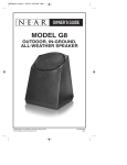
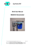
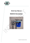
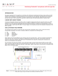
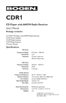
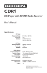
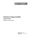
DST1
Digital Stereo Tuner
User’s Manual
© 2009 Bogen Communications, Inc.
Specifications subject to change without notice.
54-2188-01A 0904
Notice
Every effort was made to ensure that the information in this guide was complete
and accurate at the time of printing. However, information is subject to change.
Important Safety Information
WARNING: To Reduce The Risk of Fire Or Electric Shock, Do Not Expose
This Apparatus To Rain Or Moisture.
Always follow these basic safety precautions when installing and using the unit:
1.
2.
3.
4.
5.
6.
7.
8.
9.
10.
11.
12.
13.
Read these instructions.
Keep these instructions.
Heed all warnings.
Follow all instructions.
Do not use this apparatus near water.
Clean only with dry cloth.
DO NOT block any ventilation openings. Install in accordance with the manufacturer’s instructions.
Do not install near any heat sources such as radiators, heat registers, stoves,
or other apparatus (including amplifiers) that produce heat.
Do not defeat the safety purpose of the polarized or grounding-type plug. A
polarized plug has two blades with one wider than the other.A grounding-type
plug has two blades and a third grounding prong.The wide blade, or the third
prong, are provided for your safety. If the provided plug does not fit into your
outlet, consult an electrician for replacement of the obsolete outlet.
Protect the power cord from being walked on or pinched, particularly at
plugs, convenience receptacles, and the point where they exit from the apparatus.
Only use attachments/accessories specified by the manufacturer.
Unplug this apparatus during lightning storms or when unused for long periods of time.
Refer all servicing to qualified service personnel. Servicing is required when
the apparatus has been damaged in any way, such as power-supply cord or
plug is damaged, liquid has been spilled or objects have fallen into the apparatus, the apparatus has been exposed to rain or moisture, does not operate normally, or has been dropped.
2
IMPORTANT
CAUTION:TO PREVENT RISK OF ELECTRIC SHOCK, DO NOT REMOVE COVER (OR BACK). NO USER-SERVICEABLE PARTS INSIDE.
REFER SERVICING TO QUALIFIED PERSONNEL.
The lightning flash with arrowhead symbol, within an
equilateral triangle, is intended to alert the user to the
presence of uninsulated “dangerous voltage” within the
product’s enclosure that may be of sufficient magnitude to constitute a risk of electric shock to persons.
The exclamation point within an equilateral triangle is
intended to alert the user to the presence of important operating and maintenance (servicing) instructions
in the literature accompanying the appliance.
FCC Statement (Part 15) - Radio Frequency Interference
The DST1 Digital Stereo Tuner generates and uses radio frequency energy and if
not installed and used in strict accordance with the manufacturer's instructions,
may cause interference to radio and television reception. Testing is being conducted for compliance with the limits for a Class B device in accordance with the
specifications in Part 15 of the FCC Rules and Canadian D.O.C. regulations. This
testing is designed to provide reasonable protection against such interference.
However, there is no guarantee that interference will not occur in a particular installation. If this equipment does cause interference to radio or television reception, which can be determined by turning the DST1 unit off and on, the user is
encouraged to try to correct the interference by one or more of the following
measures:
- Reorient the radio or TV receiving antenna.
- Relocate the DST1 unit with respect to the radio or TV receiver or vice-versa.
- Plug the DST1 unit into a different outlet so that it and the radio or TV receiver
are on different branch circuits.
If necessary, the user should consult the dealer or an experienced radio/television
technician for additional suggestions. The user may find the following flyer, "Interference: Defining the Source," helpful.This flyer was prepared by the Federal Communications Commission (FCC) and is available from their Consumer and
Governmental Affairs Bureau website at www.fcc.gov/cgb.
3
Before You Begin
Your Bogen DST1 Digital Stereo Tuner incorporates the latest in PLL digital circuitry for reliable performance for years to come. To get the maximum benefit
from your Bogen product, please read all instructional materials provided with
the unit.
Package Contents
(1) DST1 Digital Stereo Tuner
(1) Remote Control
(1) Set, Rack Ears
(1) AM Radio Antenna (Loop)
(1) FM Radio Antenna (Dipole)
(1) Stereo Patch Cable (RCA)
(1) User’s Manual
Unpacking
The DST1 is carefully checked before leaving the factory. Inspect the shipping
carton and unit for damage caused by improper handling. If damage is found you
must file a claim with the transportation company that delivered the product.
Installing Rack Ears
A pair of rack ears are included that allow the user to mount the DST1 in a
standard 19" audio/electronics rack. To install the rack ears, refer to the diagram
and follow these steps:
1. Remove three screws from the side panel of the DST1 toward the front.
2. Place one rack ear in proper position, paying attention to correct alignment.
3. Reattach three screws.
4. Repeat procedure for second rack
ear, located on the other side of
the unit.
Important: Before installing the DST1 in
a rack, the four attached feet must be
unscrewed and removed from the
bottom of the unit.
4
Front Panel Controls
1
3
5
7
DIGITAL AM/FM STEREO TUNER
FUNCTION
POWER
INTRO
MEMORY
AM/FM
TUNING +
ST/MO
- CHANNEL +
TUNING -
2
4
6
8
7
1. POWER: Turns power to the unit ON or OFF.
2. Power LED: Lights to indicate that unit is powered ON.
3. INTRO: Scans preset stations.
4. MEMORY: Activates memory to save station preset.
5. CHANNEL +/- : Manually scrolls through programmed presets.
6. AM/FM: Switches between AM and FM operation.
7. TUNING: Tunes station frequency down (-) or up (+).
8. STEREO/MONO: Selects STEREO or MONO operation for selected FM
station.
Rear Panel Controls and Connectors
1
4
FM
GND
GND
5
7
AM
L
R
FM
75Ω
300Ω
30
AM LOOP
2
3
VOLUME
MONO
STEREO
MODEL: DST1
RISK OF ELECTRIC
SHOCK DO NOT OPEN
6
1. 75-Ohm: FM Antenna input.
2. 300-Ohm: FM Antenna input.
3. AM LOOP: AM Antenna input.
4. VOLUME: Attenuates output volume.
5. MONO: Audio connection for mono applications.
6. STEREO R/L: Audio connections for stereo applications.
7. AC Line: Connects to 120V, 60 Hz AC mains.
5
120VAC
20VAC
60HZ
0.15A
Remote Control
AM/FM
MEM
1
2
CH+
3
4
4
TU–
TU+
3
5
CH –
INTRO
ST/MO
7
6
All of the front panel control functions can also be adjusted by the remote control.
1.
2.
3.
4.
5.
6.
7.
AM/FM: Switches between AM and FM operation.
MEM: Activates MEMORY to save station preset.
CH +/CH - : Manually scrolls through stations from available presets.
TU -/TU + : Tunes station frequency down (-) or up (+).
MUTE: Mutes audio output (not available on front panel).
INTRO: Scans preset stations.
ST/MO: Selects STEREO or MONO operation for selected FM station.
Additional buttons function as follows:
VFD
POWER
1
2
1
DIGITAL
2
3
4
5
6
7
8
9
0
10+
3
4
1.
2.
3.
4.
5.
P. CALL
5
POWER: Turns power to the unit ON or OFF.
VFD: Selects different bar graph displays.
1 – 0: Manually enter digits for desired preset.
10+: Selects range in multiples of ten, for preset stations greater than “10”.
P.CALL: Allows entry of actual station numbers. Select a band (either AM or
FM), then press the P.CALL button. Next, enter the station number.
6
Antenna Connection
FM Dipole Antenna
The indoor dipole antenna provided should be adequate for normal FM
reception.
1. Connect the antenna leads to the two terminals marked 300 Ohms (FM
and GND).
2. Position the antenna for the best reception. Tack it to a wall or baseboard if
possible.
For reception when the DST1 is installed in a rack, an external antenna installed
in accordance with National Electric Codes may be required.
FM Coaxial cable connector
For applications using coaxial cable, an FM 75-Ohm coaxial cable connector is
provided.
AM Loop Antenna
The DST1 is provided with an external AM antenna for AM reception.
1. Carefully pull the antenna lead from the holding notch in the antenna and unwind the lead from the loop.
2. Connect the antenna leads to the terminals marked AM LOOP (AM and
GND).
3. Snap the antenna into the base to form a free-standing unit.
4. Position the antenna for best reception. If desired, the antenna may be permanently mounted using screws through the two holes in the base.
Audio Connections
An audio patch cable is provided to make audio connections.
1. Connect the two RCA plugs from one end of the cable to the R and L
STEREO terminals on the DST1. (Note: For mono applications, connect
one end of cable to the MONO terminal.)
2. Connect the other end of the cable to a line-level input (Hi-Z) of an audio
pre-amplifier.
Operation
Power
Press the front panel POWER button to turn on the DST1.
Turn the rear-mounted VOLUME control counterclockwise to attenuate
audio output. Turn fully clockwise for full output.
7
To Select a Band*
Press the button marked AM/FM. The current band selected (either AM or
FM) appears on the display.
You can preset up to 60 stations total for both bands. Preset stations may be
any combination of AM and FM stations. FM stations may be played in either
stereo or mono. Press the STEREO/MONO button to change mode.
To Tune a Station*
Pressing the TUNING + or TUNING - button advances to the next frequency. Pressing and holding the TUNING + or TUNING - button will activate the auto search feature. The word AUTO appears on the display, and the
search will continue to the next clear station signal. To stop the auto search
at any frequency, press either the TUNING + or TUNING - button again.
To Preset Stations*
1. Select a band and tune the first desired station.
2. Press the MEMORY button and then one of the CHANNEL +/- buttons
to select the preset number. The two-digit preset number appears on the
display. The display flashes twice and then the preset is stored.
3. Repeat the procedure for each desired preset.
To Scan Preset Stations*
1. Press the button marked INTRO. Each preset station will play for a few
seconds in turn while scanning.
2. To select a station during scanning, press the INTRO button again.
To Select Preset Stations Using Remote Control
The number buttons can be used to select a specific preset station. For
presets greater than 10, press 10+ for each multiple of 10 (for example, 10,
20, 30, etc.), then select the preset in that multiple.
Example: To select preset 52, press 10+ five times, then press 2.
Pressing P.CALL allows actual station numbers to be entered.
1. Select a band.
2. Press the P.CALL button.
3. Enter the Station numbers.
* Note: These functions are the same whether accessed from the front
panel of the DST1 or from the Remote Control.
8
Specifications
Band Coverage:
Tuning:
Channel Indicator:
Station Tuning:
Preset Memory:
Memory Scan:
Antenna Connectors:
Output:
Program Selection:
Output Terminals:
Controls:
Accessories Included:
Operating Voltage:
Dimensions:
Weight:
FM: 87.00 to 108.05 MHz
AM: 530 to 1710 kHz
PLL Synthesizer
LCD Panel
Pushbutton
60 Total stations (FM and AM)
Preset stations
FM: 75-ohm, coaxial: 300-ohm, push-release
AM: Push-release
Stereo/Mono Out via RCA jacks; 1V minimum
Pushbutton, via front panel or Remote Control
RCA Jacks
Power, Intro, Memory, Channel,
AM/FM, Tuning, Stereo/Mono,Volume
AM Loop and FM Dipole antennas
Remote Control (Uses two AAA batteries)
Stereo Patch Cable (RCA)
120V AC nominal, 60 Hz, 0.15A max.
16-7/8" W × 1-3/4" H × 10" D (without feet)
16-7/8" W × 2" H × 10" D (with feet attached)
4.75 lb.
9
Limited Warranty, Exclusion of Certain Damages
The Bogen DST1 Digital Stereo Tuner is warranted to be free from defects in material and workmanship for two (2) years from the date of sale to the original purchaser. Any part of the product
covered by this warranty that, with normal installation and use, becomes defective (as confirmed
by Bogen upon inspection) during the applicable warranty period, will be repaired or replaced by
Bogen, at Bogen’s option, provided the product is shipped insured and prepaid to: Bogen Factory
Service Department, 50 Spring Street, Ramsey, NJ 07446, USA. Repaired or replacement product
will be returned to you freight prepaid.This warranty does not extend to any of our products that
have been subjected to abuse, misuse, improper storage, neglect, accident, improper installation or
have been modified or repaired or altered in any manner whatsoever, or where the serial number
or date code has been removed or defaced.
THE FOREGOING LIMITED WARRANTY IS BOGEN’S SOLE AND EXCLUSIVE
WARRANTY AND THE PURCHASER’S SOLE AND EXCLUSIVE REMEDY. BOGEN
MAKES NO OTHER WARRANTIES OF ANY KIND, EITHER EXPRESS OR IMPLIED,
AND ALL IMPLIED WARRANTIES OF MERCHANTABILITY OR FITNESS FOR A
PARTICULAR PURPOSE ARE HEREBY DISCLAIMED AND EXCLUDED TO THE
MAXIMUM EXTENT ALLOWABLE BY LAW. Bogen's liability arising out of the manufacture, sale or supplying of products or their use or disposition, whether based upon warranty, contract, tort or otherwise, shall be limited to the price of the product. IN NO EVENT SHALL
BOGEN BE LIABLE FOR SPECIAL, INCIDENTAL OR CONSEQUENTIAL DAMAGES (INCLUDING, BUT NOT LIMITED TO, LOSS OF PROFITS, LOSS OF DATA
OR LOSS OF USE DAMAGES) ARISING OUT OF THE MANUFACTURE, SALE OR
SUPPLYING OF PRODUCTS, EVEN IF BOGEN HAS BEEN ADVISED OF THE POSSIBILITY OF SUCH DAMAGES OR LOSSES. Some States do not allow the exclusion or
limitation of incidental or consequential damages, so the above limitation or exclusion may not
apply to you.This warranty gives you specific legal rights, and you may also have other rights which
vary from State to State.
Products that are out of warranty will also be repaired by the Bogen Factory Service Department
– same address as above or call 201-934-8500. The parts and labor involved in these repairs are
warranted for 90 days when repaired by the Bogen Factory Service Department. All shipping
charges in addition to parts and labor charges will be at the owner's expense. All returns require
a Return Authorization number. For most efficient warranty or repair service, please include a
description of the failure.
12/2008
10
11
50 Spring Street, Ramsey, New Jersey 07446, USA
201-934-8500 • FAX: 201-934-9832
www.bogen.com