1
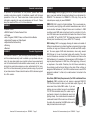
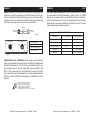
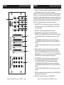
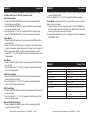
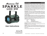
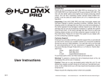
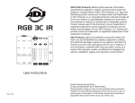
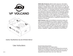
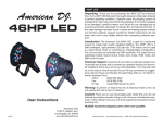
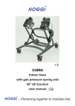
RGBW4C General Information
Unpacking: Thank you for purchasing the RGBW4C by American DJ®.
Every RGBW4C has been thoroughly tested and has been shipped in
perfect operating condition. Carefully check the shipping carton for
damage that may have occurred during shipping. If the carton appears
to be damaged, carefully inspect your fixture for any damage and be
sure all equipment necessary to operate the unit has arrived intact. In
the event damage has been found or parts are missing, please contact
our toll free customer support number for further instructions. Please
do not return this unit to your dealer without contacting customer support first.
Introduction: The RGBW4C is a 32-channel RGB, RGBW or RGBA
LED controller. Up to 8 LED fixtures or fixture groups can independently be controlled via four fixture buttons. The units control panel
includes; 9 “Static Color/Chase” buttons, which contain pre-programmed colors and chase programs, 3 programmable color preset
buttons, 4 multi function faders that control RGBW intensities, as well
as program speed, fade time, and master dimmer. There are 8 buttons used to select the operation mode, including RGB Fade, Auto
Run, Color Macro, Chase, Sound Active, Strobe, Manual RGBW and
Blackout modes. The RGBW4C is one of the simplest and most versatile LED controllers available today. It is ideal for D.J.’s, nightclubs,
lounges, bars, and anyone that wants easy control of LED Par’s, Bar’s,
Flood’s, or Panel’s.
User Instructions
Customer Support: American DJ® provides a toll free customer support line, to provide help and to answer any question should you
encounter problems during your set up or initial operation. You may
also visit us on the web at www.americandj.com for any comments or
suggestions. Service Hours are Monday through Friday 8:00 a.m. to
4:30 p.m. Pacific Standard Time.
Voice:
(800) 322-6337
Fax: (323) 582-2941
E-mail: [email protected]
To purchase parts online visit http://parts.americandj.com
Warning! To prevent or reduce the risk of electrical shock or fire, do
not expose this unit to rain or moisture.
2/12
American DJ® www.americandj.com - RGBW4C
Page 2
RGBW4C General Instructions
To optimize the performance of this product, please read these
operating instructions carefully to familiarize yourself with the basic
operations of this unit. These instructions contain important safety
information regarding the use and maintenance of this unit. Please
keep this manual with the unit, for future reference.
RGBW4C Features
•
•
•
•
•
•
•
•
9 Static Colors
RGBW Faders To Create Desired Color
9 Chases
Auto, Program, RGBW, Chase, and Sound Active Modes
Adjustable Program and Fade Speed
Adjustable Sound Sensitivity
Strobing
Blackout
RGBW4C
Product Registration
The RGBW4C carries a 1 year (365 days) limited warranty. Please fill
out the enclosed warranty card to validate your purchase and warranty. You may also register your product online at www. americandj.
com. All returned service items whether under warranty or not, must
be freight pre-paid and accompany a return authorization (R.A.) number. If the unit is under warranty you must provide a copy of your proof
of purchase invoice. Please contact American DJ® customer support
for a R.A. number.
RGBW4C DMX
Power Supply: Before plugging your unit in, be sure the source voltage in your area matches the required voltage for your American DJ®
RGBW4C. The American DJ® RGBW4C is 120v only. Only use the
included power supply to power RGBW4C.
DMX-512: DMX is short for Digital Multiplex. This is a universal pro-
tocol used by most lighting and controller manufactures as a form of
communication between intelligent fixtures and controllers. A DMX
controller sends DMX data instructions from the controller to the fixture. DMX data is sent as serial data that travels from fixture to fixture
via the DATA “IN” and DATA “OUT” XLR terminals located on all DMX
fixtures (most controllers only have a DATA “OUT” terminal).
DMX Linking: DMX is a language allowing all makes and models of
different manufactures to be linked together and operate from a single
controller, as long as all fixtures and the controller are DMX compliant. To ensure proper DMX data transmission, when using several
DMX fixtures try to use the shortest cable path possible. The order
in which fixtures are connected in a DMX line does not influence the
DMX addressing. For example; a fixture assigned a DMX address of 1
may be placed anywhere in a DMX line, at the beginning, at the end,
or anywhere in the middle. Therefore, the first fixture controlled by
the controller could be the last fixture in the chain. When a fixture is
assigned a DMX address of 1, the DMX controller knows to send DATA
assigned to address 1 to that unit, no matter where it is located in the
DMX chain.
Data Cable (DMX Cable) Requirements (For DMX and Master/Slave
Operation): DMX controller and unit require a approved DMX-512
110 Ohm Data cable for data input and data output (Figure 1). We
recommend Accu-Cable DMX cables. If you are
making your own cables, be sure to use standard
110-120 Ohm shielded cable (This cable may be
purchased at almost all professional sound and
lighting stores). Your cables should be made with
a male and female XLR connector on either end of
the cable. Also remember that DMX cable must be
daisy chained and cannot be split.
Figure 1
American DJ® www.americandj.com - RGBW4C
Page 3
American DJ® www.americandj.com - RGBW4C
Page 4
RGBW4C DMX
POWER
POWER
Notice: Be sure to follow
figures two and three when making your own
DMX512
DMX+,DMX-,COMMON
cables. Do not use
the ground lug on the XLR connector. Do not connect the cable’s shield conductor to the ground lug or allow the shield
conductor to come in contact with the XLR’s outer casing. Grounding
the shield could cause a short circuit and erratic behavior.
COMMON
DMX512 OUT
3-PIN XLR
1
2
DMX +
3
DMX -
3
1
DMX512 IN
3-PIN XLR
2
3
1
2
Figure 2
XLR Female Socket
XLR Male Socket
1 Ground
SOUND
2 Cold
2 Cold
REMOTE
CONTROL
INPUT
INPUT
OUTPUT
1 Ground
Pin 1 = Ground
REMOTE
CONTROL
INPUT
SOUND
3 Hot
XLR Pin Configuration
INPUT
OUTPUT
Pin 2 = Data Compliment (negative)
3 Hot
Pin 3 = Data True (positive)
Figure 3
RGBW4C DMX
POWER
5-Pin XLR DMX Connectors. Some manufactures use 5-pin DMX-
512 data cables for DATA transmission in place of 3-pin. 5-pin DMX
fixtures may be implemented in a 3-pin DMX line. When inserting standard 5-pin data cables in to a 3-pin line a cable adaptor must be used,
these adaptors are readily available at most electric stores. The chart
below details a proper cable conversion.
Termination reduces signal errors and
avoids signal transmission problems
and interference. It is always advisable
to connect a DMX terminal, (Resistance
120 Ohm 1/4 W) between PIN 2 (DMX-)
and PIN 3 (DMX +) of the last fixture.
3-Pin XLR to 5-Pin XLR Conversion
Conductor
3-Pin XLR Female (Out)
5-Pin XLR Male (In)
Ground/Shield
Pin 1
Pin 1
Data Compliment (- signal)
Pin 2
Pin 2
Data True (+ signal)
Pin 3
Pin 3
Not Used
Pin 4 - Do Not Use
Not Used
Pin 5 - Do Not Use
Special Note: Line Termination. When longer runs of cable are
POWER
POWER
used, you may need to use a terminator on the last unit to avoid erratic
behavior. A terminator is a 110-120 ohm 1/4 watt resistor which is connected between pins 2 and 3 of a male XLR connector (DATA + and
DATA -). This unit is inserted in the female XLR connector of the last
unit in your daisy chain to terminate the line. Using a cable terminator
(ADJ part number Z-DMX/T) will decrease the possibilities of erratic
behavior.
3
1
2
DMX512 IN
3-PIN XLR
3
1
2
Termination reduces signal errors and
avoids signal transmission problems
and interference. It is always advisable
to connect a DMX terminal, (Resistance
120 Ohm 1/4 W) between PIN 2 (DMX-)
and PIN 3 (DMX +) of the last fixture.
Figure 4
American DJ® www.americandj.com - RGBW4C
Page 5
American DJ® www.americandj.com - RGBW4C
Page 6
RGBW4C Controls and Functions
2
3
4
5
6
7
8
9
1
10
11
12
13
14
RGBW4C Controls and Functions
1. FIXTURE SELECTION - The RGBW4C can control up to 8 LED fixtures. Press one of the buttons and the corresponding LEDs above the button will light indicating which LED fixture can be controlled.
Example: Press the 1/5 button one time and the left LED will light indicating
that fixture 1 can now be controlled. Press the button a second time and
the right LED will light, indicating that fixture 5 can now be controlled. Press
the button a third time and both LEDs will light, indicating that both fixtures
can now be controlled. When you press the button the fourth time both
LEDs will turn off, indicating that you cannot control the fixtures.
2. CHASE BUTTON - Press this button to activate chase mode. Press any of the color buttons in the COLORS/CHASES grid (14) to select your desired chase.
3. BLACKOUT - Activates and deactivates blackout mode
4. COLOR MACROS - Press this button to activate the COLOR
MACROS. The COLOR MACROS can be controlled using the following:
- The RED/SPEED FADER (13) will create your own color to remain staic.
- The GREEN/FADE TIME FADER (12) will control the fade speed.
- The BLUE/MASTER DIMMER FADER (11) will control the RGB LEDs intensity.
- The WHITE/WHITE DIMMER FADER (10) will control the white LEDs intensity.
5. MANUAL RGBW - Pressing this button activates manual RGBW. When this mode is active you can press any of the color buttons located in the COLORS/CHASE grid (14). You can also use the RED/
SPEED FADER (13) to control the red LEDs intensity, the GREEN/FADE TIME FADER (12) to control the green LEDs intensity, etc.
6. AUTO PROGRAM - Pressing this button will activate the auto pro-
gram. The Auto Program can be controlled using the following:
- The RED/SPEED FADER (13) will control the program speed.
- The GREEN/FADE TIME FADER (12) will control the fade speed.
- The BLUE/MASTER DIMMER FADER (11) will control the RGB LEDs intensity.
- The WHITE/WHITE DIMMER FADER (10) will control the white LEDs intensity.
7. STROBE - Activates and deactivates strobing. Use the RED/SPEED (13) fader to adjust the strobe speed.
8. RGB FADE - Pressing this button activates RGB FADE. American DJ® www.americandj.com - RGBW4C
Page 7
American DJ® www.americandj.com - RGBW4C
Page 8
RGBW4C Controls and Functions
RGBW4C Controls and Functions - Rear Panel
The RGB FADE can be controlled using the following:
- The RED/SPEED FADER (13) will control the program speed.
- The GREEN/FADE TIME FADER (12) will control the fade speed.
- The BLUE/MASTER DIMMER FADER (11) will control the RGB LEDs intensity.
- The WHITE/WHITE DIMMER FADER (10) will control the white LEDs intensity.
9. SOUND ACTIVE MODE - Pressing this button will activate the sound active mode, the sensitivity of the sound active mode can be adjusted using knob located on the rear of the controller. Other adjustmenst can be made using the following:
- The GREEN/FADE TIME FADER (12) will control the fade speed.
- The BLUE/MASTER DIMMER FADER (11) will control the RGB LEDs intensity.
- The WHITE/WHITE DIMMER FADER (10) will control the white LEDs intensity.
15
16
17
18
15. POWER SWITCH - Accepts a DC 9V~12V, 300mA minimum, power
supply.
16. DC INPUT - Accepts a DC 9V~12V, 300mA minimum, power supply.
17. DMX OUT - Used to send DMX signal to the compatable LED fixtures.
18. SOUND SENSITIVITY - Use this knob to adjust the sound sensitivity.
10. WHITE/WHITE DIMMER FADER - Use this fader to control the output intensity of the white LEDs.
11. BLUE/MASTER DIMMER FADER - This fader has two functions.
- This fader can be used to control the blue LEDs intensity in MANUAL RGBW MODE.
- In AUTO PROGRAM, CHASE MODE, RGB FADE, COLOR MACROS, & SOUND ACTIVE MODE this fader will control the RGB LEDs output intensity.
12. GREEN/FADE TIME FADER - This fader has two functions.
- This fader can be used to control the green LEDs intensity in MANUAL RGBW MODE.
- In AUTO PROGRAM, CHASE MODE, RGB FADE, COLOR MACROS, & SOUND ACTIVE MODE this fader will control the fade time.
13. RED/SPEED FADER - This fader has three functions.
- This fader can be used to control the red LEDs intensity in MANUAL RGBW MODE.
- In AUTO PROGRAM, CHASE MODE & RGB FADE this fader will con-
trol program speed.
- In COLOR MACROS MODE this fader will create your color to remain static.
14. COLORS/CHASES/PRESETS - Press the COLOR buttons to activate desired COLOR MACROS, or when in CHASE MODE the color buttons will activate chases. See the built-in chases on page 10.
American DJ® www.americandj.com - RGBW4C
Page 9
American DJ® www.americandj.com - RGBW4C
Page 10
RGBW4C Operation
Note: When the power is switched Off and then back On, the
controller will return to the last operating mode.
Sound Active Mode:
1. Press the SOUND ACTIVE button and the corresponding LED above the button will light.
2. Use the SOUND SENSITIVITY knob located at the rear to adjust the sound sensitivity level.
3. Use the faders (10, 11, & 12) to adjust the LED intensity & fade time. The RED/SPEED fader (13) cannot be used in this mode.
Chase Mode:
1. Press the CHASE button and the corresponding LED above the button will light.
2. Press 1 of the 9 COLOR buttons (14) located in the Color/Chases region to activate a chase. Please see the chase chart on page 12.
3. Once your desired chase program has been selected, use the faders (10, 11, 12, & 13) to adjust the LED intensity, fade time, and chase speed.
Auto Mode:
1. Press the AUTO button and the corresponding LED above the but-
ton will light.
2. Use the faders (10, 11, 12, & 13) to adjust the LED intensity, fade time, and chase speed.
RGBW4C Operation
2. Press any of the 9 color buttons or use the RGBW faders to make your own desired color.
3. Use the faders (10, 11, 12, & 13) to adjust the LED intensities.
Preset Mode: Using these buttons you are able to save and recall a
chase, color, or program.
1. To save a chase, color, or program, press 1 of the 3 PRESET but-
ton for at least 3 seconds. When all of the LEDs flash 3 times, this informs you that the save was successful.
2. To recall the saved chase, color, or program, press the correspond-
ing PRESET button.
RGBW4C Chase Chart
BUTTONS IN COLORS/CHASES REGION
CHASE MODE DESCRIPTION
Color Macros Mode:
1. Press the COLOR MACROS button and the corresponding LED above the button will light.
2. Use the faders (10, 11, 12, & 13) to adjust the preferable static color, LED intensity, and fade time.
RED button
Red/Green chase
ORANGE button
Green/Blue chase
YELLOW button
Red/Blue chase
GREEN button
Red/Cyan chase
CYAN button
Green/Purple chase
BLUE button
Yellow/Blue chase
RGB Fade Mode:
1. Press the RGB FADE button and the corresponding LED above the button will light.
2. Use the faders (10, 11, 12, & 13) to adjust the LED intensity, fade time, and chase speed.
PURPLE button
Red/Green/Blue/Yellow/Purple/Cyan/White
MAGENTA button
Red/Green/Blue/Red/Blue/
Manual RGBW Color Mode:
1. Press the MANUAL RGBW button and the corresponding LED above the button will light.
American DJ® www.americandj.com - RGBW4C
Page 11
chase
Yellow
Yellow chase
WHITE button
Yellow/Purple chase
American DJ® www.americandj.com - RGBW4C
Page 12
/Cyan/
RGBW4C
Warranty
RGBW4C
Notes
1 Year Limited Warranty
MANUFACTURER’S LIMITED WARRANTY
A. American DJ, Inc. hereby warrants, to the original purchaser, American DJ and American
Audio products to be free of manufacturing defects in material and workmanship for a prescribed
period from the date of purchase (see specific warranty period on reverse). This warranty shall be
valid only if the product is purchased within the United States of America, including possessions
and territories. It is the owner’s responsibility to establish the date and place of purchase by acceptable evidence, at the time service is sought.
B.
For warranty service you must obtain a Return Authorization number (RA#) before
sending back the product. Contact American DJ, Inc. Service Department at 800-322-6337. Send
the product only to the American DJ, Inc. factory. All shipping charges must be pre-paid. If the
requested repairs or service (including parts replacement) are within the terms of this warranty,
American DJ, Inc. will pay return shipping charges only to a designated point within the United
States. If the entire instrument is sent, it must be shipped in it’s original package. No accessories
should be shipped with the product. If any accessories are shipped with the product, American DJ,
Inc. shall have no liability whatsoever for loss of or damage to any such accessories, nor for the
safe return thereof.
C. This warranty is void if the serial number has been altered or removed; if the product is
modified in any manner which American DJ, Inc. concludes, after inspection, affects the reliability
of the product; if the product has been repaired or serviced by anyone other than the American DJ,
Inc. factory unless prior written authorization was issued to purchaser by American DJ, Inc.; if the
product is damaged because not properly maintained as set forth in the instruction manual.
D.
This is not a service contract, and this warranty does not include maintenance, cleaning
or periodic check-up. During the period specified above, American DJ, Inc. will replace defective parts at its expense with new or refurbished parts, and will absorb all expenses for warranty
service and repair labor by reason of defects in material or workmanship. The sole responsibility
of American DJ, Inc. under this warranty shall be limited to the repair of the product, or replacement thereof, including parts, at the sole discretion of American DJ. All products covered by this
warranty were manufactured after January 1, 1990, and bear identifying marks to that effect.
E.
American DJ, Inc. reserves the right to make changes in design and/or improvements
upon its products without any obligation to include these changes in any products theretofore
manufactured. No warranty, whether expressed or implied, is given or made with respect to any
accessory supplied with products described above. Except to the extent prohibited by applicable
law, all implied warranties made by American DJ, Inc. in connection with this product, including
warranties of merchantability or fitness, are limited in duration to the warranty period set forth
above. And no warranties, whether expressed or implied, including warranties of merchantability
or fitness, shall apply to this product after said period has expired. The consumer’s and/or Dealer’s
sole remedy shall be such repair or replacement as is expressly provided above; and under no
circumstances shall American DJ, Inc. be liable for any loss or damage, direct or consequential,
arising out of the use of, or inability to use, this product. This warranty is the only written warranty applicable to American DJ and American Audio Products and supersedes all prior warranties and written descriptions of warranty terms and
conditions heretofore published.
American DJ® www.americandj.com - RGBW4C
Page 13
American DJ® www.americandj.com - RGBW4C
Page 14
RGBW4C
Specifications
POWER SUPPLY:
POWER CONSUMPTION:
OUTPUT:
AUDIO TRIGGER:
DIMENSIONS:
WEIGHT:
WARRANTY:
Specifications
12V DC, 500mA UL Approved.
3.6W
3-Pin XLR
Built-In Microphone
327mm(L) x 140mm(W) x 48mm(H)
12.9” (L) x 5.5” (W) x 1.9” (H)
2.4Lbs./ 1.1Kgs.
1 Year (365 Days)
Please Note: Specifications and improvements in the design
of this unit and this manual are subject to change without any
prior written notice.
©American DJ Supply
American DJ World Headquarters:
6122 S. Eastern Ave. Los Angeles, CA 90040 USA
Tel: 323-582-2650 / Fax: 323-725-6100
Web: www.americandj.com / E-mail: [email protected]
American DJ® www.americandj.com - RGBW4C
Page 15
American DJ Europe
Junostraat 2
6468 EW Kerkrade
Netherlands
[email protected] / www.americandj.eu
Tel: +31 45 546 85 00 / Fax: +31 45 546 85 99