1
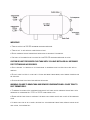
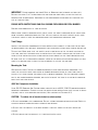
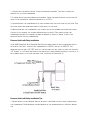
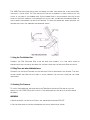
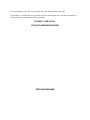
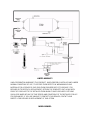
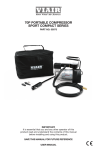
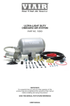
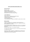
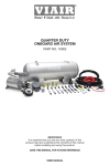
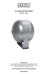
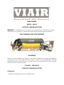
MODEL NUMBER:
M20001 – 200 PSI
ULTRA DUTY ONBOARD AIR SYSTEM
IMPORTANT: It is essential that you and any other operator of this product read and
understand the contents of this manual before installing and using this product.
SAVE THIS MANUAL FOR FUTURE REFERENCE
USER MANUAL
Thank you for purchasing the world’s first 200 PSI onboard air system. Contained in
one package, you’ll find everything you’ll need to install a high performance, 200 PSI
onboard air source for your vehicle. Please follow the instructions on the following
pages to install your new system.
P/N 20001 - VIAIR 200 PSI
ULTRA-DUTY ONBOARD AIR SYSTEM
Components:
1 2.5 Gallon, 200 PSI-rated 6 port VIAIR Air Tank
1 480C model VIAIR compressor
1 36-ft. Length of _” Air Line (for accessory and gauge installation)
1 30-foot Coil Accessory Hose
1 Inflation Gun with 200 PSI gauge
(Please check to make sure that you have four labeled packages in your Onboard Air
System kit. Each package contains the parts needed for specific areas of onboard air
installation, and may contain smaller bags within each package labeled for specific
use.)
PARTS PACKAGES
Package #1 – Air Tank Installation
4 Nuts, long bolts, washers and locking washers (mounting hardware)
+ 6 pieces rubber bushings
1 1/4” NPT Quick Connect Coupler (female)
1 1/4” NPT Quick Connect Stud (male)
1 1/4” NPT 250 PSI Safety Valve
1 1/4” NPT Drain Cock
3 1/4” NPT Compression Fittings
Package #2 – Compressor Installation
4 13/64” Nuts, shorter bolts, washers & locking washers (mounting hardware)
1 Remote Mount Air Filter Assembly
2 Remote mount air filter fittings for compressor and air filter connection
1 2-pack of replacement air filters
1 Leader Hose Bracket Clip
1 Air line for remote mounting air filter
1 Reducer – compressor-to-tank connection. (3/8” NPT female to 1/4’ NPT male)
1 4-inch Strip of Continuous Grommet Material
1 20-ft. 12 Gauge Wire with Inline Fuse holder and 30-amp fuse
1 12-gauge Ring Terminal
1 12-gauge Butt Connector
1 Self-Tapping Screw
Package #3 – Pressure Switch & Reducer
1 Pressure Switch with Relay - (165 PSI on, 200 PSI off)
1 Reducer (1/8” NPT female to 1/4” NPT male)
Package #4 – Gauge Panel Installation
1 Dash Panel – 200 PSI Gauge with ON/OFF Switch
2 13/64” Nuts, bolts, washers and locking washers – (mounting hardware)
2 Push-on Female Terminals
2 12-gauge Butt Connectors
1 12-gauge Ring Terminal
1 Self-Tapping Screw
2.5 Gallon 200 PSI Rated Air Tank Installation
Your 2.5 Gallon air tank comes with six 1/4” NPT port openings to allow installation in
many configurations on your vehicle. To insure safe and trouble-free use of your air
tank, we strongly recommend that you install the supplied drain cock and a safety
pressure relief valve. (Use contents of Package # 1).
IMPORTANT:
• Tank is rated for 200 PSI maximum working pressure.
• Tank is not to be used as a breathing device.
• Bleed pressure from tank before servicing or adding attachments.
• Use only attachments or tools rated for 200 PSI working pressure or less.
CAUTION! DO NOT PRESSURIZE YOUR TANK UNTIL YOU HAVE INSTALLED ALL NECESSARY
PORT FITTINGS AND ACCESSORIES.
• Apply sealant to threads of fittings prior to assembly and tighten each part with a
wrench.
• Do not over tighten if your port fittings are made from brass, since brass threads can
be stripped.
• Always release air from tank before servicing.
WARNING: FAILURE TO DRAIN TANK AND REMOVE CONDENSATION WILL CAUSE TANK TO
RUST PREMATURELY.
• To remove accumulated condensation inside the tank, bleed pressure from tank until
pressure is approximately 5 PSI to 20 PSI using drain cock
• Drain water from tank by opening the drain cock drain valve and close after draining
tank.
• If drain cock valve is plugged, release all air pressure from tank, remove drain valve
and clean, then reinstall.
IMPORTANT: Please observe air tank’s Date of Manufacture (stamped on tank leg).
Replace air tank 2 to 5 years from date air tank was first used, or use the date of
manufacture as reference. Adhering to air tank draining guidelines will prolong the
life of your air tank.
PLEASE NOTE: RUSTED TANKS CAN FAIL CAUSING EXPLOSIONS OR FATAL INJURIES.
Discard tank immediately if tank is rusted.
When using a safety pressure relief valve, point the safety pressure relief valve away
from your body when releasing air. Use the pull ring on the safety relief valve; open
the relief valve to vent any pressure inside the tank before servicing tank.
Tank Fittings:
Install the supplied compression fittings and/or quick connect fitting for the air tank
in areas where they are most appropriate for your installation using thread sealant or
Teflon tape. Make sure that the safety valve is installed in the top most position on
the tank, and that the drain cock is installed in the lowest position on the tank if the
tank is to be installed in any other position than upright on the tank’s mounting legs.
Be sure that all fittings are accessible later in the installation process since you will
have to plumb air lines to each fitting as needed to utilize the air tank.
Mounting the Tank:
We have included 6 pieces of rubber bushings in your tank mounting hardware. You
have the option of using two layers of rubber bushings on one of your tank lags to
slightly tilt tank toward the drain cock to improve drainage. Use the provided longer
bolts, and corresponding washers, and nuts to mount the tank to a suitable chassis or
body point on your vehicle.
480C Air Compressor Installation
Your 200 PSI Onboard Air System comes complete with a 480C, 200 PSI maximum working
pressure compressor. Please follow the installation instructions that follow to enjoy
the best use of your onboard air system. (Use contents of Package # 2)
CAUTION - To reduce risk of electrical shock or electrocution:
• Do not disassemble the compressor. Do not attempt repairs or modifications. Refer to
qualified service agencies for all service and repairs.
• Do not use this product in or area where it can fall or be pulled into water or
liquids.
• Do not reach for this product if it has fallen into liquid.
• Use this compressor with 12-volt DC systems only.
• This product should never be left unattended during use.
Guidelines for Selecting Mounting Location:
The selection of proper mounting location for your air compressor will help ensure a
long and trouble free compressor service life. Please pay close attention to the
following:
• Select a flat & secure location where the compressor can be mounted upright.
• To maximize air compressor performance, locate compressor as close to the battery
as possible so that length of positive lead wire required is at a minimum.
• Choose mounting location that is as cool as possible and away from heat sources.
• This compressor is moisture & dust resistant, but NOT WATERPROOF or DUSTPROOF. Do
not mount compressor in locations where the unit is likely to come in contact with
water or excessive dirt.
• For compressor with remote filter mounting, select compressor’s mounting location
where air line can be routed from compressor air inlet to remote inlet air filter. Make
sure that the remote inlet air filter is located in a dry location, away from water.
• You will also want to select a compressor mounting location where the leader hose
bracket can be mounted to secure the 2 ft. leader hose.
• If it is necessary to mount the air compressor further from the battery, such as
inside your vehicle or in the bed of your pickup, use a minimum 8 AWG positive lead wire
for remote installation.
• Do not mount compressor near areas where flammable liquids are stored. 480C
Compressor Wiring:
1. Disconnect ground cable from vehicle’s battery.
2. Temporarily position the air compressor in the location where it will be mounted.
3. Route ground wire to the negative post of the battery or to an appropriate
grounding point and cut ground wire to length as needed.
4. Mount the 480C air compressor with the four sets of 13/64” (5 mm) bolts, nuts,
washers, and locking washers provided. Use of thread locker is recommended.
5. Use 3/8” NPT female to 1/4’ NPT male reducer to install compressor to open 1/4” NPT
port on 200 PSI-rated air tank.
6. NOTE: For Remote Inlet Air Filter Installation, refer to Remote Inlet Air Filter
Installation Instruction included in the Remote Inlet Air Filter Pack for installation of Remote
Inlet Air Filter.
7. This air compressor comes with a 2 ft. heavy duty heat resistant stainless steel
braided leader hose with _” fittings. This leader hose is designed to prolong the life of
your air line. Do not remove this leader hose from air compressor.
8. IMPORTANT: Please note; the leader hose that came with your compressor has a
built-in inline check valve pre-installed. Do not remove inline check valve from leader
hose.
9. Select a proper location to mount leader hose with hose bracket provided. Avoid
locations where leader hose may become tangled with wires and other hoses.
10. To mount hose bracket, drill holes with 3/16” drill bit and push self–anchoring
hose bracket pin into hole. Route leader hose through hose bracket and secure hose
by pressing bracket clamp into locked position.
11. To remove hose from the hose bracket, simply press down on the hose clamp release
tab to release bracket clamp.
12. Connect compressor’s positive lead wire to one of the leads of your pressure
switch.
13. Make sure that your compressor setup is properly fused. The 480C pulls
approximately 20 maximum amps of power.
14. Always locate fuse as close as possible to power source.
15. Before connecting to power source, check to make sure that all connections are
made properly.
16. Connect and test compressor system by running the compressor for a short time to
build up pressure in your air tank.
17. Once air pressure reaches preset cut out pressure of your pressure switch, the
compressor will shut off. Inspect all air line connections for leaks with soap and
water solution. If a leak is detected, the air line may not be cut squarely or pushed all
the way in. Tighten connections if needed.
480C OPERATING INSTRUCTIONS
IMPORTANT: The 480C has a maximum working pressure of 200 PSI and is capable of 50%
duty cycle at 200 PSI. Always operate the compressor at or below the
MAXIMUM PRESSURE RATING of the compressor. Operation exceeding maximum pressure
ratings and or duty cycle will result in damage to air compressor.
1. Your air compressor is equipped with an AUTOMATIC THERMAL OVERLOAD PROTECTOR.
This feature is designed to protect the air compressor from overheating and causing
permanent damage to your air compressor. The thermal overload protector will
automatically cut off power to your air compressor should the internal operating
temperature of the air compressor rise above safe levels during excessive use.
2. Should at any time during use, your air compressor automatically shuts off; do not
attempt to restart air compressor. Turn power switch to the air compressor to the OFF
position. The automatic thermal overload protector will automatically reset when
internal temperature of the air compressor drops below safe level. After allowing air
compressor to cool off for about 30 minutes, you can safely resume use of the air
compressor by turning on the air compressor.
3. To prevent discharge of your vehicle’s battery and to provide peak performance, we
strongly recommend that you keep the vehicle’s engine running while using the air
compressor.
4. ONLY OPERATE THE AIR COMPRESSOR IN WELL-VENTILATED AREAS.
480C Compressor Maintenance & Repairs
1. Periodically check all electrical and fitting connections. Clean and tighten as
needed.
2. Periodically check all mounting screws. Tighten as needed.
3. Replace air filter element periodically. Replacement frequency depends on operating
frequency and operating environment. For frequent use in dusty environment, you
should replace air filter element more often.
4. Regularly clean dust and dirt from compressor.
5. Your air compressor is equipped with permanently lubricated, maintenance free
motor. Never lubricate compressor.
6. Repairs should be performed by Manufacturer or Manufacturer’s Authorized Service
Agencies only.
CAUTION: Never touch the air compressor or fittings connected to the air compressor
with bare hands during or immediately after use. Leader hose and fittings will become
very HOT during and after use.
480C Compressor Installation Tips
1. Always use the remote intake filter option when possible. This will extend the
service life of your compressor.
2. If noise reduction from vibration is desired, using the remote mount option for the
inlet filter can reduce operation noise by up to 25%.
3. Always mount the compressor at a point higher than the inlet port of the tank. This
will keep moisture from being able to seep back to the tank.
4. When mounting the compressor, use a paint pen on the rubber isolators and cover
the side to go against the chassis or mounting location. Then, simply stamp the
compressor against the chassis to make an imprint of exactly where to drill the
mounting holes for the compressor.
Pressure Switch with Relay Installation
Your VIAIR Constant Duty Onboard Air System comes complete with a pressure switch
with relay that will turn on the compressor at 165 PSI, and off at 200 PSI. The
pressure switch has a 1/8” NPT inlet at the bottom that will need to have the supplied
1/8” female to 1/4” male reducer fitting installed (using thread sealant) to allow it to
be plumbed directly to your air tank. (Use contents of Package # 3)
Pressure Switch with Relay Installation Tips
1. Never install your pressure switch in direct line from the inlet port coming from
the compressor. Tank pressure can be misread by the pressure switch. Instead, mount
the
pressure switch on the tank where it receives air pressure reading from deflected air
in the tank.
2. Never use a pressure switch that is rated beyond your compressor’s rated Maximum
Working Pressure (200 PSI).
3. Replace with Pressure Switch with Relay P/N 90118 if the pressure switch becomes
faulty or fails in the future.
Dash Panel Gauge Installation
Your VIAIR Constant Duty Onboard Air System comes complete with a Dash Panel Gauge
to monitor the pressure of your 2.5 gallon 200 PSI rated VIAIR air tank. Additionally,
the Dash Panel Gauge has an ON/OFF switch preinstalled that will allow you to turn
the system off by cutting power to the pressure switch with relay that you have
already installed. We recommend that you install a master ON/OFF switch to allow the
system to be turned off any time you anticipate leaving the vehicle parked for any
length of time, and to avoid draining the vehicle’s battery unnecessarily due to a slow
air leak in your system. (Use contents of Package #4).
IMPORTANT:
Each Dash Panel Gauge has been tested and calibrated. The air inlet on this gauge has a
factory installed compression fitting. DO NOT attempt to tighten or loosen the body of
this compression fitting. Any adjustments will cause the gauge to malfunction and void
warranty. Do not pressurize gauge over 200 PSI.
1. Select Mounting Location for Dash Panel Gauge
Select a mounting location with a rigid mounting surface such as the bottom edge of
the dashboard. Use the panel as a template and mark off two mounting points to be
drilled. Carefully drill two 13/64” diameter holes as marked.
2. Air Line Connection to Dash Panel Gauge
Remove the collar of the compression fitting from the back of the Dash Panel Gauge.
Do not loosen of tighten the body of the compression fitting. Insert air line tubing
through this collar, and then push air line tubing onto the barb of the compression
fitting until the air line completely covers the barb. Tighten collar onto the body of
the compression fitting with a wrench.
3. Routing Air Line to Air Source
Route the air line tubing on the Dash Panel Gauge to the air source. Do not cut air
line yet. In some cases a hole may need to be drilled to enable the air line to pass
through to the air source. Make sure that the air line tubing is protected from any
sharp edges of the drilled hole using grommet strip supplied. Connect to the tank using
the 1/4” compression fitting supplied.
Installation Tips:
• When cutting air line tubing, always cut as squarely as possible. Use a hose cutter or
razor blade.
• When routing air line tubing, always remember to avoid sharp edges, heat sources and
tight bends. (Air line must be routed at least 12 inches from exhaust systems & other
heat sources.)
IMPORTANT - Drilling through firewall: Always be sure of what is on the other side of
the firewall before drilling. Take care not to damage your vehicle’s electronic systems
or components when drilling.
4. Wiring the ON/OFF Switch
Attach one of the two remaining female terminal connectors to the wire that was
routed from the pressure switch trigger wire (Small Red Wire on pressure switch with
relay) There are two male spade connectors on the back of the ON/OFF switch. Connect
this female terminal connector to one of the male spade connector on the ON/OFF
switch.
Next, attach appropriate size ring terminal provided in the kit to the end of the wire
with the Inline Fuse. (The ring terminal should be about 12” from the inline fuse.) This
wire is referred to as the power wire. Temporarily position the ring terminal at the
power source and route power wire to the dash panel gauge, measure and cut to
appropriate length. (If additional wire is necessary, use 16 AWG wire.) Attach the
remaining female terminal connector to end of power wire, and connect to male spade
connector on the ON/OFF switch. (Note: Do not connect gauge to power source at this
time.)
5. Wiring the Dash Panel Gauge for Illumination
There are two wires, one red and one black connected to the light bulb of the gauge.
Connect the red wire to a suitable fused dash panel circuit. Use the quick splice
connector included in the kit for wire connections. The black wire is to be connected
to a suitable ground source.
6. Mounting the Dash Panel Gauge
With all electrical and air line tubing routed and connected properly, mount the dash
panel gauge using the two 13/64” nuts, bolts, and washers included with the Dash
Panel Gauge. Make sure that no electrical wires or air line can be contacted by
vehicle pedal operation, or by use of any safety equipment. Use provided zip ties to
secure air line and electrical wiring.
7. Connect to Power Source
Before connecting the power wire to a power source, check to make sure that the
ON/OFF switch on the dash panel gauge is in the OFF position. Connect the ring terminal
of the power wire to power source. (This is the wire described in Step 4, which is
connected to the ON/OFF switch of the dash panel gauge.)
8. Test Your Onboard Air System
Your Onboard Air System installation is now complete. Run the compressor to build
pressure in the air tank. When air pressure reaches the pressure switch cut out
pressure, the compressor will shut off. Inspect all air line connections for leaks with
soap and water solution and spray with a spray bottle onto connections to check for
leaks. If leaks are detected, push air line may not be cut squarely or pushed all the
way in.
TIRE INFLATION GUN
The VIAIR Tire Inflation gun is used for airing up tires, and adding air to any inflatable
item with a valve stem. The Tire Inflation Gun has a normally closed lever style air
chuck at the end of its rubber hose. After connection to an air source such as an air
tank via the quick connect stud preinstalled in the unit, air may be discharged from the
gun by simply squeezing the inflation trigger. To check air pressure, simply release the
trigger and check the onboard air pressure gauge.
1. Using the Tire Inflation Gun:
Connect the Tire Inflation Gun to an air hose and connect to a tire valve stem or
similar inflation collar by securing the folding lever on the Inflation Gun air chuck.
2. Filling Tires and other Inflatable Items:
Squeeze the Inflation Trigger on the Inflation Gun by squeezing the trigger. This will
allow stored air from the air tank to flow through the gun into your tire or other
inflatable.
3. Checking Tire Pressure:
To check tire pressure, release Inflation Trigger on Inflation Gun and allow the
needle of the 0-200 PSI gauge to settle. Tire pressure will be able to be read when
released.
WARNING:
• Never operate the Inflation Gun at any pressure exceeding 200 PSI.
• Use caution when attached or removing air chuck from valve stems.
• Always ensure that tire valve stems are tight before inflating tires.
• Be careful to never inflate any tire or other inflatable past its rated pressure to
avoid explosion, or possible injury or death.
P/N 20001 - VIAIR 200 PSI ULTRA DUTY ONBOARD AIR SYSTEM
INSTALLATION DIAGRAM
LIMITED WARRANTY
VIAIR CORPORATION WARRANTS THIS PRODUCT, WHEN PROPERLY INSTALLED AND UNDER
NORMAL CONDITIONS OF USE, TO BE FREE FROM DEFECTS IN WORKMANSHIP AND
MATERIALS FOR A PERIOD OF ONE YEAR FROM PROVIDED DATE OF PURCHASE. FOR
REPAIRS OR TO RECEIVE A REPLACEMENT, RETURN THE COMPLETE UNIT ALONG WITH
PROOF OF PURCHASE TO THE RETAILER FROM WHOM IT WAS PURCHASED. RETURNS
SHOULD BE MADE WITHIN THE TIME PERIOD AND CONDITIONS OF THE RETAILER’S POLICY
FOR EXCHANGES. IF YOU ARE UNABLE TO CONTACT YOUR DEALER, CONTACT VIAIR
DIRECTLY FOR REPAIRS OR REPLACEMENT AT OUR OPTION.
MODEL NUMBER:
20001 – ULTRA DUTY ONBOARD AIR SYSTEM
PLEASE NOTE:
THIS WARRANTY COVERS PRODUCT DEFECTS ONLY. IT DOES NOT COVER INCIDENTAL OR
CONSEQUENTIAL DAMAGES AS RESULT OF MIS USE OR ABUSE.