1
IMBA-690AM2 Motherboard
IMBA-690AM2 Motherboard
Page i
IMBA-LUKE-R20 Half-size CPU Card
IMBA-690AM2 Motherboard
Revision
Date
Version
Changes
2007-08
1.00
Initial release
Page ii
IMBA-690AM2 Motherboard
Copyright
COPYRIGHT NOTICE
The information in this document is subject to change without prior notice in order to
improve reliability, design and function and does not represent a commitment on the part
of the manufacturer.
In no event will the manufacturer be liable for direct, indirect, special, incidental, or
consequential damages arising out of the use or inability to use the product or
documentation, even if advised of the possibility of such damages.
This document contains proprietary information protected by copyright. All rights are
reserved. No part of this manual may be reproduced by any mechanical, electronic, or
other means in any form without prior written permission of the manufacturer.
TRADEMARKS
All registered trademarks and product names mentioned herein are used for identification
purposes only and may be trademarks and/or registered trademarks of their respective
owners.
Page iii
IMBA-LUKE-R20 Half-size CPU Card
IMBA-690AM2 Motherboard
Manual Conventions
WARNING!
Warnings appear where overlooked details may cause damage to the equipment or result
in personal injury. Warnings should be taken seriously. Warnings are easy to recognize.
The word “warning” is written as “WARNING,” both capitalized and bold and is followed by
text. The text is the warning message. A warning message is shown below:
WARNING:
This is an example of a warning message. Failure to adhere to warning
messages may result in permanent damage to the IMBA-690AM2 or
personal injury to the user. Please take warning messages seriously.
CAUTION!
Cautionary messages should also be heeded to help reduce the chance of losing data or
damaging the IMBA-690AM2. Cautions are easy to recognize. The word “caution” is
written as “CAUTION,” both capitalized and bold and is followed. The italicized text is the
cautionary message. A caution message is shown below:
Page iv
IMBA-690AM2 Motherboard
CAUTION:
This is an example of a caution message. Failure to adhere to cautions
messages may result in permanent damage to the IMBA-690AM2.
Please take caution messages seriously.
NOTE:
These messages inform the reader of essential but non-critical information. These
messages should be read carefully as any directions or instructions contained therein can
help avoid making mistakes. Notes are easy to recognize. The word “note” is written as
“NOTE,” both capitalized and bold and is followed by text. The text is the cautionary
message. A note message is shown below:
NOTE:
This is an example of a note message. Notes should always be read.
Notes contain critical information about the IMBA-690AM2. Please take
note messages seriously.
Page v
IMBA-LUKE-R20 Half-size CPU Card
IMBA-690AM2 Motherboard
Packing List
NOTE:
If any of the components listed in the checklist below are missing,
please do not proceed with the installation. Contact the IEI reseller or
vendor you purchased the IMBA-690AM2 from or contact an IEI sales
representative directly. To contact an IEI sales representative, please
send an email to [email protected].
The items listed below should all be included in the IMBA-690AM2 package.
1 x IMBA-690AM2 single board computer
1 x IDE cable
1 x I/O shielding
2 x SATA power cables
4 x SATA cables
2 x Dual RS-232 cables
1 x Backplate for AMD Socket AM2
1 x Mini jumper pack
1 x Utility CD
1 x QIG (quick installation guide)
Images of the above items are shown in Chapter 3.
Page vi
IMBA-690AM2 Motherboard
Table of Contents
1
INTRODUCTION..................................................................................................... 1
1.1 OVERVIEW ................................................................................................................. 2
1.1.1 IMBA-690AM2 Features.................................................................................... 2
1.2 IMBA-690AM2 OVERVIEW ...................................................................................... 3
1.2.1 IMBA-690AM2 Overview Photo ........................................................................ 3
1.2.2 IMBA-690AM2 Peripheral Connectors and Jumpers........................................ 4
1.2.3 Technical Specifications..................................................................................... 5
2
DETAILED SPECIFICATIONS ............................................................................. 9
2.1 DIMENSIONS ............................................................................................................ 10
2.1.1 Board Dimensions............................................................................................ 10
2.1.2 External Interface Panel Dimensions ...............................................................11
2.2 DATA FLOW ...............................................................................................................11
2.3 COMPATIBLE PROCESSORS ....................................................................................... 13
2.3.1 Supported Processors ...................................................................................... 13
2.3.2 DDR2 Memory Controller ............................................................................... 13
2.3.3 Processor Electrical Interfaces........................................................................ 14
2.3.4 Processor Power Management ........................................................................ 14
2.4 AMD 690G NORTHBRIDGE CHIPSET ....................................................................... 14
2.4.1 PCI Express Interface ...................................................................................... 14
2.4.1.1 PCIe x16 Expansion.................................................................................. 14
2.4.1.2 PCIe GbE Ethernet.................................................................................... 15
2.4.1.3 PCIe Mini Card ......................................................................................... 16
2.4.2 Acceleration Features ...................................................................................... 16
2.4.3 Display Support ............................................................................................... 17
2.4.3.1 TV Out ...................................................................................................... 18
2.4.3.2 Multiple Display Features......................................................................... 18
2.4.3.3 DVI ........................................................................................................... 18
2.5 AMD SB600 SOUTHBRIDGE CHIPSET...................................................................... 18
2.5.1 CPU Interface .................................................................................................. 18
2.5.2 A-Link Xpress II interface to the Northbridge ................................................. 19
Page vii
IMBA-LUKE-R20 Half-size CPU Card
IMBA-690AM2 Motherboard
2.5.3 PCI Host Bus Controller.................................................................................. 19
2.5.4 USB Controllers............................................................................................... 20
2.5.5 SMBus Controller ............................................................................................ 21
2.5.6 Interrupt Controller ......................................................................................... 21
2.5.7 DMA Controller ............................................................................................... 21
2.5.8 LPC host bus controller ................................................................................... 22
2.5.9 SATA II AHCI Controller ................................................................................. 22
2.5.10 IDE Controller ............................................................................................... 23
2.5.11 AC Link interface ........................................................................................... 24
2.5.12 Timers............................................................................................................. 26
2.5.13 RTC (Real Time Clock) .................................................................................. 26
2.5.14 Power Management ....................................................................................... 26
2.5.15 Hardware Monitor ......................................................................................... 27
2.6 LPC BUS COMPONENTS ........................................................................................... 27
2.6.1 LPC Bus Overview........................................................................................... 27
2.6.2 BIOS Chipset.................................................................................................... 28
2.6.3 TPM Module .................................................................................................... 28
2.6.4 Super I/O chipset.............................................................................................. 29
2.6.4.1 Super I/O LPC Interface ........................................................................... 29
2.6.4.2 Super I/O Floppy Disk Drive (FDD) Controller....................................... 29
2.6.4.3 Super I/O 16C550 UARTs ........................................................................ 30
2.6.4.4 Super I/O Enhanced Hardware Monitor ................................................... 30
2.6.4.5 Super I/O Fan Speed Controller................................................................ 30
2.6.4.6 Super I/O Keyboard and Mouse Controller .............................................. 30
2.6.4.7 Super I/O Infrared ..................................................................................... 31
2.6.5 Serial Port Chipset........................................................................................... 31
2.7 ENVIRONMENTAL AND POWER SPECIFICATIONS ....................................................... 31
2.7.1 System Monitoring ........................................................................................... 31
2.7.2 Operating Temperature and Temperature Control........................................... 32
2.7.3 Power Consumption......................................................................................... 33
3
UNPACKING .......................................................................................................... 35
3.1 ANTI-STATIC PRECAUTIONS ...................................................................................... 36
3.2 UNPACKING.............................................................................................................. 36
3.2.1 Unpacking Precautions.................................................................................... 36
Page viii
IMBA-690AM2 Motherboard
3.3 UNPACKING CHECKLIST ........................................................................................... 37
3.3.1 Package Contents............................................................................................. 37
3.4 OPTIONAL ITEMS ...................................................................................................... 39
4
CONNECTOR PINOUTS...................................................................................... 41
4.1 PERIPHERAL INTERFACE CONNECTORS .................................................................... 42
4.1.1 IMBA-690AM2 Layout..................................................................................... 42
4.1.2 Peripheral Interface Connectors ..................................................................... 43
4.1.3 External Interface Panel Connectors............................................................... 45
4.2 INTERNAL PERIPHERAL CONNECTORS ...................................................................... 45
4.2.1 Audio Connector (8-pin) .................................................................................. 45
4.2.2 Audio Connector (10-pin) ................................................................................ 46
4.2.3 Audio CD In Connector (4-pin) ....................................................................... 47
4.2.4 Auxiliary Audio Connector .............................................................................. 48
4.2.5 ATX Power Connector ..................................................................................... 49
4.2.6 Compact Flash Socket...................................................................................... 51
4.2.7 Digital Input/Output (DIO) Connector............................................................ 53
4.2.8 Fan Connector ................................................................................................. 54
4.2.9 Floppy Disk Connector (34-pin)...................................................................... 55
4.2.10 Front Panel Connector (14-pin) .................................................................... 57
4.2.11 IDE Connector (40-pin) ................................................................................. 58
4.2.12 Infrared Interface Connector ......................................................................... 59
4.2.13 PCI Express Mini Card Connector ................................................................ 60
4.2.14 PCIe Mini Card LED Connector ................................................................... 63
4.2.15 PCI Slot.......................................................................................................... 64
4.2.16 PCI Express x16 Slot...................................................................................... 67
4.2.17 Power Connector ........................................................................................... 70
4.2.18 Parallel Port Connector ................................................................................ 70
4.2.19 RS-422/485 Connector (for COM3)............................................................... 72
4.2.20 SATA Drive Connectors ................................................................................. 72
4.2.21 Serial Port Connectors .................................................................................. 74
4.2.22 SPDIF Connector........................................................................................... 75
4.2.23 Trusted Platform Module (TPM) Connector.................................................. 76
4.2.24 TV Out Connector .......................................................................................... 77
4.2.25 USB Connectors (Internal) ............................................................................ 78
Page ix
IMBA-LUKE-R20 Half-size CPU Card
IMBA-690AM2 Motherboard
4.3 EXTERNAL PERIPHERAL INTERFACE CONNECTOR PANEL ......................................... 80
4.3.1 Audio Connector .............................................................................................. 80
4.3.2 DVI and VGA Combo Connector..................................................................... 81
4.3.3 Keyboard/Mouse Connector ............................................................................ 83
4.3.4 LAN and Dual USB Combo Connectors.......................................................... 84
4.3.5 Serial Port Connectors (COM1 and COM2 ) .................................................. 86
5
INSTALLATION .................................................................................................... 87
5.1 ANTI-STATIC PRECAUTIONS ...................................................................................... 88
5.2 INSTALLATION CONSIDERATIONS ............................................................................. 89
5.2.1 Installation Notices .......................................................................................... 89
5.2.2 Installation Checklist ....................................................................................... 90
5.3 UNPACKING.............................................................................................................. 91
5.3.1 Unpacking Precautions.................................................................................... 91
5.4 CPU, CPU COOLING KIT AND DIMM INSTALLATION ............................................. 92
5.4.1 AMD Socket AM2 CPU Installation ................................................................ 92
5.4.2 Cooling Kit Installation ................................................................................... 94
5.4.3 DIMM Installation ........................................................................................... 96
5.5 JUMPER SETTINGS .................................................................................................... 97
5.5.1 CF Card Setup ................................................................................................. 98
5.5.2 Clear CMOS Jumper........................................................................................ 99
5.5.3 COM 3 Function Select Jumper..................................................................... 100
5.5.4 COM3 Voltage Setup Jumper......................................................................... 101
5.6 CHASSIS INSTALLATION ......................................................................................... 102
5.6.1 Airflow............................................................................................................ 102
5.6.2 Motherboard Installation............................................................................... 103
5.7 INTERNAL PERIPHERAL DEVICE CONNECTIONS...................................................... 103
5.7.1 Peripheral Device Cables .............................................................................. 103
5.7.2 ATA Flat Cable Connection ........................................................................... 103
5.7.3 Dual RS-232 Cable Connection..................................................................... 104
5.7.4 SATA Drive Connection ................................................................................. 105
5.7.5 FDD Cable Connection ................................................................................. 107
5.7.6 Parallel Port Cable with Slot Bracket ........................................................... 108
5.7.7 USB Cable (Four Port).................................................................................. 109
5.8 EXTERNAL PERIPHERAL INTERFACE CONNECTION ..................................................110
Page x
IMBA-690AM2 Motherboard
5.8.1 Audio Connection............................................................................................ 111
5.8.2 DVI Display Device Connection.....................................................................112
5.8.3 LAN Connection (Single Connector) ..............................................................113
5.8.4 PS/2 Keyboard and Mouse Connection ..........................................................113
5.8.5 Serial Device Connection ...............................................................................114
5.8.6 USB Connection (Dual Connector) ................................................................115
5.8.7 VGA Monitor Connection ...............................................................................116
6
BIOS SCREENS.....................................................................................................119
6.1 INTRODUCTION ...................................................................................................... 120
6.1.1 Starting Setup................................................................................................. 120
6.1.2 Using Setup .................................................................................................... 120
6.1.3 Getting Help................................................................................................... 121
6.1.4 Unable to Reboot After Configuration Changes............................................ 121
6.1.5 BIOS Menu Bar.............................................................................................. 121
6.2 MAIN ..................................................................................................................... 122
6.3 ADVANCED ............................................................................................................. 123
6.3.1 CPU Configuration........................................................................................ 124
6.3.2 IDE Configuration ......................................................................................... 126
6.3.2.1 IDE Master, IDE Slave ........................................................................... 127
6.3.3 Floppy Configuration..................................................................................... 133
6.3.4 Super IO Configuration.................................................................................. 134
6.3.5 Hardware Health Configuration.................................................................... 139
6.3.6 ACPI Configuration ....................................................................................... 140
6.3.7 APM Configuration........................................................................................ 142
6.3.8 Trusted Computing ......................................................................................... 144
6.3.9 Remote Access Configuration ........................................................................ 145
6.3.10 USB Configuration....................................................................................... 149
6.3.10.1 USB Mass Storage Device Configuration ............................................. 151
6.4 PCI/PNP ................................................................................................................ 153
6.5 BOOT ..................................................................................................................... 156
6.5.1 Boot Settings Configuration........................................................................... 157
6.5.2 Boot Device Priority ...................................................................................... 159
6.5.3 Hard Disk Drives ........................................................................................... 160
6.5.4 Removable Drives .......................................................................................... 161
Page xi
IMBA-LUKE-R20 Half-size CPU Card
IMBA-690AM2 Motherboard
6.6 SECURITY............................................................................................................... 162
6.7 CHIPSET ................................................................................................................. 163
6.7.1 NorthBridge Chipset Configuration .............................................................. 164
6.7.2 ECC Configuration ........................................................................................ 165
6.7.3 Internal Graphics Configuration ................................................................... 167
6.7.4 SouthBridge Configuration............................................................................ 170
6.7.5 CPU Over Frequency Function ..................................................................... 171
6.8 EXIT ....................................................................................................................... 174
7
SOFTWARE DRIVERS ....................................................................................... 177
7.1 AVAILABLE SOFTWARE DRIVERS ............................................................................ 178
7.2 DRIVER CD AUTO-RUN .......................................................................................... 178
7.3 AMD 690G CHIPSET DRIVER INSTALLATION......................................................... 180
7.4 BROADCOM LAN DRIVER (FOR GBE LAN) INSTALLATION .................................. 185
7.5 REALTEK AC`97 AUDIO DRIVER (ALC655) INSTALLATION .................................. 190
7.5.1 BIOS Setup ..................................................................................................... 190
7.5.2 Driver Installation ......................................................................................... 190
7.6 WEBPAM RAID UTILITY DRIVER INSTALLATION ................................................. 195
A
BIOS OPTIONS .................................................................................................... 201
B
DIO INTERFACE................................................................................................. 207
B.1 DIO INTERFACE INTRODUCTION ........................................................................... 208
B.2 DIO CONNECTOR PINOUTS ................................................................................... 208
B.3 ASSEMBLY LANGUAGE SAMPLES ........................................................................... 209
B.3.1 Enable the DIO Input Function..................................................................... 209
B.3.2 Enable the DIO Output Function .................................................................. 209
C
WATCHDOG TIMER ...........................................................................................211
D
ADDRESS MAPPING.......................................................................................... 215
D.1 ADDRESS MAP ...................................................................................................... 216
D.2 1ST MB MEMORY ADDRESS MAP ......................................................................... 216
D.3 IRQ MAPPING TABLE ............................................................................................ 217
D.4 DMA CHANNEL ASSIGNMENTS ............................................................................. 217
E
HAZARDOUS MATERIALS DISCLOSURE ................................................... 219
Page xii
IMBA-690AM2 Motherboard
E.1 HAZARDOUS MATERIAL DISCLOSURE TABLE FOR IPB PRODUCTS CERTIFIED AS
ROHS COMPLIANT UNDER 2002/95/EC WITHOUT MERCURY ..................................... 220
F
RAID SETUP ........................................................................................................ 223
F.1 INTRODUCTION ...................................................................................................... 224
F.1.1 Precautions .................................................................................................... 224
F.2 FEATURES AND BENEFITS ....................................................................................... 225
F.3 ACCESSING THE AMD SB600 RAID UTILITY ....................................................... 225
G
INDEX.................................................................................................................... 229
Page xiii
IMBA-LUKE-R20 Half-size CPU Card
IMBA-690AM2 Motherboard
List of Figures
Figure 1-1: IMBA-690AM2 Overview ............................................................................................3
Figure 2-1: IMBA-690AM2 Dimensions (mm)............................................................................10
Figure 2-2: External Interface Panel Dimensions (mm)...........................................................11
Figure 2-3: Data Flow Block Diagram........................................................................................12
Figure 2-4: DIMM Sockets...........................................................................................................13
Figure 2-5: PCIe x1 Expansion Slot ...........................................................................................15
Figure 2-6: Broadcom PCI GbE Controllers..............................................................................15
Figure 2-7: PCIe Mini Card Connector.......................................................................................16
Figure 2-8: Display Interfaces ....................................................................................................17
Figure 2-9: PCI Expansion Slots ................................................................................................20
Figure 2-10: USB Connectors.....................................................................................................21
Figure 2-11: SATA Connectors ..................................................................................................23
Figure 2-12: IDE Connector ........................................................................................................24
Figure 2-13: Audio Codec and Audio Jacks .............................................................................25
Figure 2-14: LPC BUS Components ..........................................................................................28
Figure 4-1: Connector and Jumper Locations..........................................................................42
Figure 4-2: Audio Connector Location (9-pin)..........................................................................46
Figure 4-3: Audio Connector Pinouts (10-pin)..........................................................................47
Figure 4-4: Audio CD In Connector Pinouts (4-pin) .................................................................48
Figure 4-5: Auxiliary Audio Connector Location (4-pin) .........................................................49
Figure 4-6: ATX Power Connector Pinout Locations...............................................................50
Figure 4-7: CF Card Socket Location ........................................................................................52
Figure 4-8: DIO Connector Locations........................................................................................54
Figure 4-9: Fan Connector Location..........................................................................................55
Figure 4-10: 34-pin FDD Connector Location ...........................................................................56
Figure 4-11: Front Panel Connector Pinout Locations (14-pin)..............................................57
Figure 4-12: IDE Device Connector Locations .........................................................................58
Figure 4-13: Infrared Connector Pinout Locations ..................................................................60
Page xiv
IMBA-690AM2 Motherboard
Figure 4-14: PCIe Mini Card Connector Location.....................................................................61
Figure 4-15: PCIe Mini Card LED Connector Location ............................................................63
Figure 4-16: PCI Slot Location ...................................................................................................65
Figure 4-17: PCI Express x16 Slot Locations ...........................................................................68
Figure 4-18: Power Connector Location ...................................................................................70
Figure 4-19: Parallel Port Connector Location .........................................................................71
Figure 4-20: RS-422/485 Connector Location...........................................................................72
Figure 4-21: SATA Drive Connector Locations ........................................................................73
Figure 4-22: Serial Connector Pinout Locations ......................................................................74
Figure 4-23: SPDIF Connector Pinout Locations .....................................................................75
Figure 4-24: TPM Connector Pinout Locations ........................................................................76
Figure 4-25: TV Connector Pinout Locations ...........................................................................78
Figure 4-26: USB Connector Pinout Locations ........................................................................79
Figure 4-27: IMBA-690AM2 External Peripheral Interface Connector....................................80
Figure 4-28: Audio Connector ....................................................................................................81
Figure 4-29: DVI-D Connector Pinouts ......................................................................................82
Figure 4-30: VGA Connector ......................................................................................................83
Figure 4-31: PS/2 Pinouts ...........................................................................................................84
Figure 4-32: RJ-45 Ethernet Connector.....................................................................................85
Figure 4-33: Pinout Locations ....................................................................................................86
Figure 5-1: Install the CPU..........................................................................................................93
Figure 5-2: IEI Cooling Kit for IMBA-690AM2............................................................................94
Figure 5-3: Install the CPU cooler..............................................................................................95
Figure 5-4: Installing a DIMM......................................................................................................96
Figure 5-5: CF Card Setup Jumper Location ............................................................................99
Figure 5-6: Clear CMOS Jumper ............................................................................................. 100
Figure 5-7: COM3 Function Select Jumper Location............................................................ 101
Figure 5-8: COM3 Voltage Setup Jumper Location............................................................... 102
Figure 5-9: IDE Cable Connection .......................................................................................... 104
Figure 5-10: Dual RS-232 Cable Installation .......................................................................... 105
Figure 5-11: SATA Drive Cable Connection........................................................................... 106
Figure 5-12: SATA Power Drive Connection.......................................................................... 106
Page xv
IMBA-LUKE-R20 Half-size CPU Card
IMBA-690AM2 Motherboard
Figure 5-13: FDD Cable Connection ....................................................................................... 107
Figure 5-14: LPT Cable Connection........................................................................................ 108
Figure 5-15: Connect the LPT Device..................................................................................... 109
Figure 5-16: Four Port USB Cable Connection...................................................................... 110
Figure 5-17: Audio Connectors ............................................................................................... 111
Figure 5-18: DVI Connector ..................................................................................................... 112
Figure 5-19: LAN Connection .................................................................................................. 113
Figure 5-20: PS/2 Keyboard/Mouse Connector ..................................................................... 114
Figure 5-21: Serial Device Connector..................................................................................... 115
Figure 5-22: USB Connector.................................................................................................... 116
Figure 5-23: VGA Connector ................................................................................................... 117
Figure 7-1: Introduction Screen .............................................................................................. 179
Figure 7-2: Available Drivers ................................................................................................... 179
Figure 7-3: Chipset Driver Installation Program.................................................................... 180
Figure 7-4: Chipset Driver Installation Welcome Screen ..................................................... 181
Figure 7-5: Chipset Driver Installation License Agreement ................................................. 181
Figure 7-6: Select Destination Folder..................................................................................... 182
Figure 7-7: Chipset Driver Installing Screen.......................................................................... 182
Figure 7-8: Welcome Screen ................................................................................................... 183
Figure 7-9: Chipset Driver Readme File Information ............................................................ 183
Figure 7-10: Chipset Driver Installation Complete ................................................................ 184
Figure 7-11: Setup Complete................................................................................................... 185
Figure 7-12: Windows Control Panel...................................................................................... 186
Figure 7-13: System Icon ......................................................................................................... 187
Figure 7-14: Device Manager Tab ........................................................................................... 187
Figure 7-15: Device Manager List ........................................................................................... 188
Figure 7-16: Search for Suitable Driver.................................................................................. 189
Figure 7-17: Locate Driver Files .............................................................................................. 189
Figure 7-18: Location Browsing Window............................................................................... 190
Figure 7-19: Select the Audio CODEC.................................................................................... 191
Figure 7-20: Locate the Setup Program Icon......................................................................... 192
Figure 7-21: Preparing Setup Screen ..................................................................................... 192
Page xvi
IMBA-690AM2 Motherboard
Figure 7-22: InstallShield Wizard Welcome Screen .............................................................. 193
Figure 7-23: Audio Driver Software Configuration................................................................ 193
Figure 7-24: Audio Driver Digital Signal................................................................................. 194
Figure 7-25: Audio Driver Installation .................................................................................... 194
Figure 7-26: Restart the Computer ......................................................................................... 195
Figure 7-27: Chipset Driver Installation Program.................................................................. 196
Figure 7-28: Chipset Drivers.................................................................................................... 196
Figure 7-29: RAID Utility Icon .................................................................................................. 197
Figure 7-30: SATA RAID Setup Program Icon ....................................................................... 197
Figure 7-31: Welcome Screen ................................................................................................. 198
Figure 7-32: WebPAM License Agreement ............................................................................ 198
Figure 7-33: Select WebPAM Installation Destination .......................................................... 199
Figure 7-34: WebPAM Ready to Install................................................................................... 199
Figure 7-35: WebPAM Installation .......................................................................................... 200
Figure 7-36: WebPAM Installation Complete ......................................................................... 200
Page xvii
IMBA-LUKE-R20 Half-size CPU Card
IMBA-690AM2 Motherboard
List of Tables
Table 1-1: Technical Specifications.............................................................................................7
Table 2-1: Power Consumption..................................................................................................33
Table 3-1: Package List Contents ..............................................................................................38
Table 3-2: Package List Contents ..............................................................................................40
Table 4-1: Peripheral Interface Connectors ..............................................................................44
Table 4-2: Rear Panel Connectors .............................................................................................45
Table 4-3: Audio Connector Pinouts (9-pin) .............................................................................46
Table 4-4: Audio Connector Pinouts (10-pin) ...........................................................................47
Table 4-5: Audio CD In Connector Pinouts...............................................................................48
Table 4-6: Auxiliary Audio Connector Pinouts (4-pin) .............................................................49
Table 4-7: ATX Power Connector Pinouts ................................................................................50
Table 4-8: CF Card Socket Pinouts............................................................................................53
Table 4-9: DIO Connector Pinouts .............................................................................................54
Table 4-10: CPU Fan Connector Pinouts ..................................................................................55
Table 4-11: System Fan Connector Pinouts .............................................................................55
Table 4-12: 34-pin FDD Connector Pinouts ..............................................................................57
Table 4-13: Front Panel Connector Pinouts (14-pin) ...............................................................58
Table 4-14: IDE Connector Pinouts ...........................................................................................59
Table 4-15: Infrared Connector Pinouts ....................................................................................60
Table 4-16: PCIe Mini Card Connector Pinouts ........................................................................62
Table 4-17: PCIe Mini Card LED Connector Pinouts................................................................63
Table 4-18: PCI Slot .....................................................................................................................67
Table 4-19: PCIe x16 Side A Pinouts .........................................................................................69
Table 4-20: PCI Express x16 Slot Pinouts.................................................................................69
Table 4-21: Power Connector Pinouts.......................................................................................70
Table 4-22: Parallel Port Connector Pinouts ............................................................................71
Table 4-23: RS-422/485 Connector Pinouts ..............................................................................72
Table 4-24: SATA Drive Connector Pinouts..............................................................................73
Page xviii
IMBA-690AM2 Motherboard
Table 4-25: Serial Connector Pinouts........................................................................................75
Table 4-26: SPDIF Connector Pinouts.......................................................................................76
Table 4-27: TPM Connector Pinouts..........................................................................................77
Table 4-28: TV Port Connector Pinouts.....................................................................................78
Table 4-29: JUSB1 Port Connector Pinouts..............................................................................79
Table 4-30: JUSB2 Port Connector Pinouts..............................................................................79
Table 4-31: DVI-D Connector Pinouts........................................................................................82
Table 4-32: VGA Connector Pinouts..........................................................................................83
Table 4-33: PS/2 Connector Pinouts..........................................................................................84
Table 4-34: LAN Pinouts .............................................................................................................85
Table 4-35: RJ-45 Ethernet Connector LEDs ............................................................................85
Table 4-36: USB Port Pinouts.....................................................................................................85
Table 4-37: RS-232 Serial Port Pinouts .....................................................................................86
Table 5-1: Jumpers......................................................................................................................98
Table 5-2: CF Card Setup Jumper Settings ..............................................................................98
Table 5-3: Clear CMOS Jumper Settings................................................................................ 100
Table 5-4: COM3 Function Select Jumper Settings .............................................................. 101
Table 5-5: COM3 Voltage Setup Jumper Settings ................................................................. 102
Table 5-6: IEI Provided Cables ................................................................................................ 103
Table 6-1: BIOS Navigation Keys ............................................................................................ 121
Page xix
IMBA-LUKE-R20 Half-size CPU Card
IMBA-690AM2 Motherboard
BIOS Menus
Menu 1: Main ............................................................................................................................. 122
Menu 2: Advanced.................................................................................................................... 124
Menu 3: CPU Configuration..................................................................................................... 125
Menu 4: IDE Configuration ...................................................................................................... 126
Menu 5: IDE Master and IDE Slave Configuration................................................................. 128
Menu 6: IDE Master and IDE Slave Configuration................................................................. 133
Menu 7: Super IO Configuration ............................................................................................. 134
Menu 8: Hardware Health Configuration................................................................................ 139
Menu 9: ACPI Configuration.................................................................................................... 141
Menu 10:Advanced Power Management Configuration ....................................................... 142
Menu 11: Trusted Computing .................................................................................................. 144
Menu 12: Remote Access Configuration [Advanced]........................................................... 145
Menu 13: USB Configuration................................................................................................... 149
Menu 14: USB Mass Storage Device Configuration.............................................................. 151
Menu 15: PCI/PnP Configuration ............................................................................................ 154
Menu 16: Boot ........................................................................................................................... 156
Menu 17: Boot Settings Configuration................................................................................... 157
Menu 18: Boot Device Priority Settings ................................................................................. 159
Menu 19: Hard Disk Drives ...................................................................................................... 160
Menu 20: Removable Drives.................................................................................................... 161
Menu 21: Security..................................................................................................................... 162
Menu 22: Chipset...................................................................................................................... 163
Menu 23:NorthBridge Chipset Configuration ........................................................................ 164
BIOS Menu 24: ECC Configuration Chipset Configuration.................................................. 165
BIOS Menu 25: Internal Graphics Configuration................................................................... 168
Menu 26:SouthBridge Chipset Configuration ....................................................................... 170
Menu 27: ICP Over Clocking.................................................................................................... 172
Menu 28:Exit.............................................................................................................................. 174
Page xx
IMBA-690AM2 Motherboard
Glossary
AC ’97
Audio Codec 97
IDE
Integrated Data Electronics
ACPI
Advanced Configuration and
I/O
Input/Output
Power Interface
L1 Cache Level 1 Cache
APM
Advanced Power Management
L2 Cache Level 2 Cache
ARMD
ATAPI Removable Media Device
LCD
Liquid Crystal Display
ASKIR
Shift Keyed Infrared
LPT
Parallel Port Connector
ATA
Advanced Technology
LVDS
Low Voltage Differential Signaling
Attachments
MAC
Media Access Controller
BIOS
Basic Input/Output System
OS
Operating System
CFII
Compact Flash Type 2
PCI
Peripheral Connect Interface
CMOS
Complementary Metal Oxide
PIO
Programmed Input Output
Semiconductor
PnP
Plug and Play
CPU
Central Processing Unit
POST
Power On Self Test
Codec
Compressor/Decompressor
RAM
Random Access Memory
COM
Serial Port
SATA
Serial ATA
DAC
Digital to Analog Converter
S.M.A.R.T Self Monitoring Analysis and
DDR
Double Data Rate
DIMM
Dual Inline Memory Module
SPD
Serial Presence Detect
DIO
Digital Input/Output
S/PDI
Sony/Philips Digital Interface
DMA
Direct Memory Access
SDRAM
Synchronous Dynamic Random
EIDE
Enhanced IDE
EIST
Enhanced Intel SpeedStep
SIR
Serial Infrared
Technology
UART
Universal Asynchronous
Reporting Technology
Access Memory
Receiver-transmitter
FDD
Floppy Disk Drive
FDC
Floppy Disk Connector
USB
Universal Serial Bus
FFIO
Flexible File Input/Output
VGA
Video Graphics Adapter
FIFO
First In/First Out
FSB
Front Side Bus
IrDA
Infrared Data Association
HDD
Hard Disk Drive
Page xxi
THIS PAGE IS INTENTIONALLY LEFT BLANK
Page xxii
IMBA-690AM2 Motherboard
Chapter
1
1
Introduction
Page 1
IMBA-690AM2 Motherboard
1.1 Overview
The IMBA-690AM2 ATX form factor motherboard is an AMD Socket AM2 processor
platform. Up to 8GB of DDR2 DIMM SDRAM and up to four SATA II hard disk drives (HDD)
are supported. SATA drives can be installed in a RAID configuration. High-performance
PCI Express (PCIe) Gigabit Ethernet (GbE) connectivity is integrated into the system. Six
PCI expansion slots along with eight USB 2.0 channels enable system flexibility and
expansion. Multi-display interfaces and dual display functions ensure display versatility.
Support for a (optional) trusted platform module (TPM) provides additional system security
during system boot-up.
1.1.1 IMBA-690AM2 Features
Some of the IMBA-690AM2 features are listed below.
Supports the following AMD Socket AM2 processors:
o
o
o
AMD Athlon™ 64 X2 dual-core
AMD Athlon™ 64
AMD Sempron™
Supports four 240-pin 400MHz, 533MHz, 667MHz or 800MHz DDR2 DIMMs
with a maximum capacity of 8GB.
Four SATA II drives with transfer rates of 3.0Gb/s supported
Two Ultra ATA 133, Ultra ATA 100, Ultra ATA 66 or Ultra ATA 33 IDE HDDs
supported
Eight USB 2.0 devices supported
Six PCI and one PCIe x16 interfaces supported
Dual PCIe GbE Ethernet connectors
Multi-display interfaces (DVI, VGA and TV-out) and dual display functions
supported
ATX form factor
RoHS compliant
Supports ATX power supplies
Page 2
IMBA-690AM2 Motherboard
1.2 IMBA-690AM2 Overview
1.2.1 IMBA-690AM2 Overview Photo
The IMBA-690AM2 has a wide variety of peripheral interface connectors. Figure 1-1 is a
labeled photo of the peripheral interface connectors on the IMBA-690AM2.
Figure 1-1: IMBA-690AM2 Overview
Page 3
IMBA-690AM2 Motherboard
1.2.2 IMBA-690AM2 Peripheral Connectors and Jumpers
The IMBA-690AM2 has the following connectors on-board:
2 x Audio connectors
1 x AUX IN connector
1 x ATX power connector
1 x CD IN connector
1 x CompactFlash® card slot
1 x Digital input/output connector
4 x DDR2 DIMM slots
2 x Fan connectors
1 x FDD connector
1 x Front panel connector
1 x IDE disk drive connector
1 x Infrared interface connector
1 x Mini PCIe socket
1 x Mini PCIe LED connector
1 x Parallel port connector
6 x PCI slots
1 x PCIe x16 slot
1 x Power connector
1 x RS-422/485 connector (for COM3)
4 x Serial port connectors
4 x Serial ATA II (SATA II) drive connectors
1 x SPDIF connector
1 x TPM connector
1 x TV Out connector
2 x USB 2.0 connectors (support four USB 2.0 devices)
The IMBA-690AM2 has the following external peripheral interface connectors on the
board rear panel.
3 x Audio Jacks
Page 4
IMBA-690AM2 Motherboard
2 x Ethernet connectors
1 x DVI-D connector
2 x PS/2 connectors
2 x Serial port connectors
4 x USB connectors
1 x VGA connector
The IMBA-690AM2 has the following on-board jumpers:
CF card setup
Clear CMOS
RS-232/422/485 COM3 setup
COM3 voltage setup
1.2.3 Technical Specifications
IMBA-690AM2 technical specifications are listed in Table 1-1. See Chapter 2 for details.
Specification
Form Factor
IMBA-690AM2
ATX
AMD Socket AM2 Athlon™ 64 X2
System CPU
AMD Socket AM2 Athlon™ 64
AMD Socket AM2 Sempron™
HyperTransport™
A 1000 MHz HyperTransport™ interfaces is supported
Technology
Northbridge: AMD 690G
System Chipset
Southbridge: AMD SB600
Four 240-pin DDR2 DIMM sockets support four 400MHz,
Memory
533MHz, 667MHz, or 800MHz un-buffered DDR2 DIMMs
with a maximum capacity of 2GB each
Page 5
IMBA-690AM2 Motherboard
Super I/O
Fintek F71882FG
VGA integrated in the AMD® 690G with ATI RadeonTM
Xpress 1250 Graphic Core
Display Interface
Supports HDTV resolutions up to 1080i by component
interface
DVI by AMD® 690G with dual display support
BIOS
AMI Flash BIOS
Audio
RealTek ALC655 with AC’97 codec 5.1 channel
LAN
Dual Broadcom BCM5787M PCIe GbE controllers
Five RS-232 serial ports
COM
One RS-232/422/485 serial port
USB2.0
Eight USB 2.0 devices supported
One 40-pin IDE connector connects to two Ultra
IDE
ATA33/66/100/133 devices
SATA
Four 3.0Gb/s SATA II drives supported
FDD
One floppy disk drive supported
Keyboard/mouse
Two PS/2 connectors
Six PCI slots
Expansion
One PCIe x16 slot
One 8-bit digital input/output connector; 4-bit input/4-bit
Digital I/O
output
Watchdog Timer
Software programmable 1-255 sec. by super I/O
Infrared
One IrDA connector by Super I/O
Power Supply
ATX power
Page 6
IMBA-690AM2 Motherboard
[email protected], [email protected], [email protected] and [email protected]
Power Consumption
(AMD® Athlon 64 X2 dual-core 6000+ CPU and four 512MB
533MHz DDR2 DIMM)
Temperature
0ºC – 60ºC (32ºF - 140ºF)
Humidity (operating)
5%~95% non-condensing
Dimensions (LxW)
305mm x 244mm
Weight (GW)
1500g
Table 1-1: Technical Specifications
NOTE:
Due to the limitation of Windows 32-bit operating system, when more than
4GB of physical memory is installed, the actual memory available for the
operating system is less than 4GB. The Windows 64-bit operating system
doesn't have such limitation.
Page 7
IMBA-690AM2 Motherboard
THIS PAGE IS INTENTIONALLY LEFT BLANK
Page 8
IMBA-690AM2 Motherboard
Chapter
2
2 Detailed Specifications
Page 9
IMBA-690AM2 Motherboard
2.1 Dimensions
2.1.1 Board Dimensions
The dimensions of the board are listed below:
Length:
305mm
Width:
244mm
Figure 2-1: IMBA-690AM2 Dimensions (mm)
Page 10
IMBA-690AM2 Motherboard
2.1.2 External Interface Panel Dimensions
External peripheral interface connector panel dimensions are shown in Figure 2-2.
Figure 2-2: External Interface Panel Dimensions (mm)
2.2 Data Flow
Figure 2-3 shows the data flow between the two on-board chipsets and other components
installed on the motherboard and described in the following sections of this chapter.
Page 11
IMBA-690AM2 Motherboard
Figure 2-3: Data Flow Block Diagram
Page 12
IMBA-690AM2 Motherboard
2.3 Compatible Processors
2.3.1 Supported Processors
The IMBA-690AM2 supports the following AMD Socket AM2 processors
AMD Athlon™ 64 processor
AMD Athlon™ 64 X2 dual-core processor
AMD Sempron™ processor
2.3.2 DDR2 Memory Controller
All processors supported by the IMBA-690AM2 CPU card have their own DDR2 memory
controller. The DDR2 controller has the following features:
Up to 12.8GB/s memory bandwidth
800MHz 128-bit DDR2 SDRAM controller
Supports up to four un-buffered DDR2 DIMM
Each DIMM has a maximum capacity of 2GB
The DDR2 controller on the processor is interfaced to four DIMM sockets on the
IMBA-690AM2.
Figure 2-4: DIMM Sockets
Page 13
IMBA-690AM2 Motherboard
2.3.3 Processor Electrical Interfaces
The supported processors have the following electrical interfaces:
HyperTransport™ technology: LVDS-like differential, unidirectional
DDR SDRAM: SSTL_2 per JEDEC specification
Clock, reset, and test signals also use DDR SDRAM-like electrical
specifications.
2.3.4 Processor Power Management
The supported processors have the following power management features:
Multiple low-power states including C1E
System Management Mode (SMM)
ACPI compliant, including support for processor performance states
2.4 AMD 690G Northbridge Chipset
2.4.1 PCI Express Interface
The AMD 690G PCIe bus is compliant with the PCI Express 1.1a. The AMD 690G has one
PCIe x16 interfaces and four PCIe x1 interfaces. The PCIe x16 interface supports a PCIe
x16 graphics card. Two of the PCIe x1 lanes are connected to two PCIe GbE controllers
and a third PCIe x1 lane is connected to a Mini-PCIe expansion slot.
2.4.1.1 PCIe x16 Expansion
One of two PCIe interfaces from the AMD 690G is interfaced to a PCIe x16 expansion slot.
See Figure 2-5. A standard PCIe x16 expansion board can be inserted into the slot to
provide additional functionality to the system.
Page 14
IMBA-690AM2 Motherboard
Figure 2-5: PCIe x1 Expansion Slot
2.4.1.2 PCIe GbE Ethernet
Two PCIe x1 lanes from the AMD 690G Northbridge are interfaced to two Broadcom
BCM5787M PCIe GbE controllers shown in Figure 2-6 below.
Figure 2-6: Broadcom PCI GbE Controllers
The Broadcom BCM5787M is a 10/100/1000BASE-T Ethernet LAN controller. The
BCM5787M combines a triple-speed IEEE 802.3 compliant Media Access Controller
(MAC) with a triple-speed Ethernet transceiver, a PCIe bus interface, and an on-chip
buffer memory. Some of the BCM5787 controller features are listed below:
Page 15
IMBA-690AM2 Motherboard
Integrated 10/100/1000BASE-T transceiver
Automatic MDI crossover function
PCIe v1.0a
10/100/1000BASE-T full/half-duplex MAC
Wake on LAN support meeting the ACPI requirements
Statistics for SNMP MIB II, Ethernet-like MIB, and Ethernet MIB (802.3z,
clause 30)
Serial EEPROM or serial flash support
2.4.1.3 PCIe Mini Card
One PCIe x1 lanes from the AMD 690G Northbridge are interfaced to a PCIe Mini Card
connector shown in Figure 2-6 below.
Figure 2-7: PCIe Mini Card Connector
2.4.2 Acceleration Features
The AMD 690G has the following 2D acceleration features:
Highly optimized 128-bit engine, capable or processing multiple pixels per
clock
Supports a maximum resolution of 2048x1536 @ 32bpp
Game acceleration including support for Microsoft's DirectDraw
Page 16
IMBA-690AM2 Motherboard
The AMD 690G also has the following 3D acceleration features:
Full DirectX 9.0 support
3D Texture support, including projective 3D textures
Anti-aliasing using multi-sampling algorithm with support for 2, 4, and 6
samples
New generation rendering engine provides top 3D performance
Support for OpenGL format for Indirect Vertices in Vertex Walker
Motion video acceleration features on the AMD 690G include:
Enhanced MPEG-2 hardware decode acceleration
MPEG-4 decode support
Hardware acceleration for WMV9 playback
Supports top quality DVD and time-shifted SDTV/HDTV television playback
with low CPU usage
2.4.3 Display Support
The AMD 690G supports dual independent displays. The following display interface
connectors are on the IMBA-690AM2:
TV Out
DVI-D
VGA
Figure 2-8: Display Interfaces
Page 17
IMBA-690AM2 Motherboard
2.4.3.1 TV Out
TV Out features include:
Integrated TV encoder from Xilleon products with integrated Avivo™
Supports Macrovision 7.1 copy protection standard (required by DVD players)
Supports the formats of component, composite and S-video outputs
2.4.3.2 Multiple Display Features
The Multiple display features include
Dual independent displays including one digital output
Resolution, refresh rates, and display data can be completely independent for
the two display paths
Supports both interlaced and non-interlaced displays
2.4.3.3 DVI
DVI support features include:
Supports a TMDS interface, enabling DVI <1650 Mbps/channel with 165 MHz
pixel clock rate per link
HDCP 1.1 support on data stream with on-chip key storage
2.5 AMD SB600 Southbridge Chipset
2.5.1 CPU Interface
The AMD SB600 Southbridge chipset supports the following AMD Socket AM2
processors:
AMD Athlon™ 64 X2 dual-core processor
AMD Athlon™ 64 processor
AMD Sempron™ processor
Page 18
IMBA-690AM2 Motherboard
2.5.2 A-Link Xpress II interface to the Northbridge
The AMD SB600 Southbridge is connected to the AMD 690G Northbridge chipset through
an A-Link Xpress II interface. Some of the A-Link Xpress II interface features are listed
below:
1/2/4-lane A-Link Xpress II interface
Dynamic detection of lane configuration
High data transfer bandwidth
2.5.3 PCI Host Bus Controller
The PCI interface on the AMD SB600 Southbridge is compliant with the PCI Revision 2.3
implementation. Some of the features of the PCI interface are listed below.
PCI rev. 2.3 specifications
PCI bus at 33 MHz
Up to 6 master devices
40-bit addressing
Interrupt steering for plug-n-play devices
Concurrent PCI operations
Hiding of PCI devices by BIOS/hardware
Spread spectrum
The PCI bus is interfaced to six PCI expansion slots (see Figure 2-9).
Page 19
IMBA-690AM2 Motherboard
Figure 2-9: PCI Expansion Slots
2.5.4 USB Controllers
Eight of the ten high-speed, full-speed or low-speed USB ports on the AMD SB600 are
implemented on the IMBA-690AM2. High-speed USB 2.0, with data transfers of up to
480MB/s, is enabled with the AMD SB600 integrated Enhanced Host Controller Interface
(EHCI) compliant host controller. USB full-speed and low-speed signaling are enabled
with the integrated Universal Host Controller Interface (UHCI) controllers.
The USB controller supports the following:
USB 1.1 (“Low Speed”, “Full Speed”) and 2.0 (“High Speed”)
ACPI S1~S5
Legacy keyboard/mouse
USB debug port
Port disable with individual control
Four of the eight USB ports are interfaced to two 8-pin headers on the IMBA-690AM2.
Four more USB ports are interfaced to four external USB connectors. See Figure 2-10.
Page 20
IMBA-690AM2 Motherboard
Figure 2-10: USB Connectors
2.5.5 SMBus Controller
The AMD SB600 Southbridge chipset SMBus Controller is SMBus Rev. 2.0 compliant and
supports SMBALERT # signal / GPIO.
2.5.6 Interrupt Controller
The AMD SB600 Southbridge interrupt controller supports the following:
IOAPIC/X-IO APIC mode for 24 channels of interrupts
8259 legacy mode for 15 interrupts
Programmable level/edge triggering on each channels
Serial interrupt on quiet and continuous modes
2.5.7 DMA Controller
The AMD SB600 Southbridge has two cascaded 8237 DMA controllers that support the
following:
PC/PCI/DMA
LPC DMA
Page 21
IMBA-690AM2 Motherboard
Type F DMA
2.5.8 LPC host bus controller
The AMD SB600 Southbridge LPC interface complies with the LPC 1.1 and LPC 1.2
specifications. The LPC bus from the Southbridge is connected to the following
components:
BIOS chipset
Super I/O chipset
TPM connector
Some of the features of the LPC bus are listed below.
Supports LPC based super I/O and flash devices
Supports two master/DMA devices
Supports TPM version 1.1/1.2 devices for enhanced security
Supports SPI devices
2.5.9 SATA II AHCI Controller
The integrated SATA controllers on the AMD SB600 Southbridge support four SATA II
drives on the IMBA-690AM2 with independent DMA operations. The SATA controller
supports the following:
Four SATA ports, complying with SATA 2.0 specifications
SATA II 3.0GHz PHY, with backward compatibility with 1.5GHz
RAID stripping (RAID 0) across all 4 ports
RAID mirroring (RAID 1) across all 4 ports
RAID 10 (4 ports needed)
Both AHCI mode and IDE mode
Advanced power management with AHCI mode
The four SATA connectors are shown in Figure 2-11.
Page 22
IMBA-690AM2 Motherboard
Figure 2-11: SATA Connectors
2.5.10 IDE Controller
The AMD SB600 Southbridge IDE controller is interfaced to a single IDE connector. The
IDE controller has the following specifications.
Single PATA channel support
Support PIO, multi-word DMA, and Ultra DMA 33/66/100/133 modes
32x32 byte buffers on each channel for buffering
Swap bay support by tri-state IDE signals
Supports Messages Signaled Interrupt (MSI)
Integrated IDE series resistor
The IDE connector is shown in Figure 2-12.
Page 23
IMBA-690AM2 Motherboard
Figure 2-12: IDE Connector
2.5.11 AC Link interface
The AMD SB600 Southbridge AC Link interface has the following features:
Supports for both audio and modem codecs
Compliant with AC-97 codec Rev. 2.3
6/8 channel support on audio codec
Multiple functions for audio and modem codec operations
Bus master logic
Supports up to 3 codecs simultaneously
Supports SPDIF output
AC Link
The AC Link Interface is connected to a 16-bit, full-duplex AC'97 Rev. 2.3 compatible
six-channel RealTek ALC655 audio codec. The ALC655 is then connected to three
externally accessible audio jacks. See Figure 2-13.
Page 24
IMBA-690AM2 Motherboard
Figure 2-13: Audio Codec and Audio Jacks
Some of the features of the ALC655 are listed below:
Complies with PC99/2001 systems audio performance requirements
Complies with Microsoft WHQL/WLP 2.0 audio requirements
16-bit Stereo full-duplex CODEC with 48KHz sampling rate
Compliant with AC'97 Rev 2.3 specifications
o
o
o
o
o
Front-Out, Surround-Out, MIC-In and LINE-In Jack Sensing
14.318MHz -> 24.576MHz PLL to eliminate crystal
12.288MHz BITCLK input
Integrated PCBEEP generator to save buzzer
Interrupt capability
Three analog line-level stereo inputs with 5-bit volume control, LINE_IN, CD,
AUX
High-quality differential CD input
Two analog line-level mono inputs: PCBEEP, PHONE-IN
Dedicated Front-MIC input for front panel applications (software selectable)
Boost preamplifier for MIC input
LINE input shared with surround output; MIC input shared with Center and
LFE output
Built-in 50mW/20ohm amplifier for both Front-out and Surround-Out
External Amplifier Power Down (EAPD) capability
Power management and enhanced power saving features
Supports Power-Off CD function
Page 25
IMBA-690AM2 Motherboard
Adjustable VREFOUT control
Supports 48KHz S/PDIF output, complying with AC'97 Rev 2.3 specifications
Supports 32K/44.1K/48KHz S/PDIF input
Power support: Digital: 3.3V; Analog: 3.3V/5V
EAX™ 1.0 & 2.0 compatible
Direct Sound 3D™ compatible
A3D™ compatible
I3DL2 compatible
HRTF 3D positional audio
10-band software equalizer
Voice cancellation and key shifting in Karaoke mode
AVRack® Media Player
Configuration Panel for improved user convenience
2.5.12 Timers
The AMD SB600 south bridge has the following timers
8254-compatible timer
Microsoft High Precision Event Timer (HPET)
ACPI power management timer
2.5.13 RTC (Real Time Clock)
256 bytes of battery backed RAM is provided by the real time clock (RTC) integrated into
the AMD SB600. The RTC keeps track of the time and stores system data even when the
system is turned off. Some of the features of the RTC are listed below:
256-byte battery backed CMOS RAM
Hardware supported century rollover
RTC battery monitoring feature
2.5.14 Power Management
ACPI specification 3.0 compliant power management schemes on the AMD SB600
include:
Page 26
IMBA-690AM2 Motherboard
Supports C2, C3, C4
Supports C1e and C3 pop-up (AMD platform only)
Supports S0, S1, S2, S3, S4, and S5
Supports SpeedStep™
Full support for On-Now™
Supports CPU SMM, generating SMI# signal upon power management
events
GPIO supports on external wake up events
Supports CLKRUN# on PCI power management
Provides clock generator and CPU STPCLK# control
Hardware monitoring support
Support for ASF
2.5.15 Hardware Monitor
The AMD SB600 has the following hardware monitoring features:
Supports 3 Independent Fan Control outputs
Supports 4 thermal diode temperature sensing functions
Supports 1 AMDSI function
2.6 LPC Bus Components
2.6.1 LPC Bus Overview
The LPC bus is connected to components listed below:
BIOS chipset
Super I/O chipset
Serial port chipset
TPM module connector
Page 27
IMBA-690AM2 Motherboard
Figure 2-14: LPC BUS Components
2.6.2 BIOS Chipset
The BIOS chipset has a licensed copy of AMI BIOS installed on the chipset. Some of the
BIOS features are listed below:
AMI Flash BIOS
SMIBIOS (DMI) compliant
Console redirection function support
PXE (Pre-boot Execution Environment) support
USB booting support
2.6.3 TPM Module
A TPM connector on the IMBA-690AM2 is interfaced to the AMD SB600 Southbridge
through the LPC bus. The AMD SB600 Southbridge supports TPM version 1.1 and TPM
version 1.2 devices for enhanced security. Three TPM are available from IEI. The three IEI
TPM are listed below:
Infineon TPM module
Sinosun TPM module
Winbond TPM module
Page 28
IMBA-690AM2 Motherboard
For more information about these modules please refer to Chapter 3 or contact the
IMBA-690AM2 reseller or vendor. Alternatively, please contact IEI at [email protected].
2.6.4 Super I/O chipset
The Fintek F71882FG Super I/O chipset is connected to the AMD SB600 Southbridge
through the LPC bus. The Fintek F71882FG is an LPC interface-based Super I/O device
that comes with Environment Controller integration. Some of the features of the Fintek
F71882FG chipset are listed below:
Comply with LPC Spec. 1.0
Support DPM (Device Power Management), ACPI
6/12 VID pins for VRM9.0/10.0/11.0* and CPU VID OTF (On The Fly)
Easy voltage sensor I/O (VSI/VSO) for Vcore change use.
Support automatic and dynamic voltage change function (2 Turbo pins
Turbo1# and Turbo2# for VID usage)
Provides one FDC, two UARTs, KBC and Parallel Port
H/W monitor functions
SPI interface for BIOS usage
Support AMD SID/SIC interface and Intel SST/PECI interface
32 GPIO Pins for flexible application
24/48 MHz clock input
Packaged in 128-PQFP and powered by 3.3VCC
Some of the Super I/O features are described in more detail below:
2.6.4.1 Super I/O LPC Interface
The LPC interface on the Super I/O complies with the AMD® Low Pin Count Specification
Rev. 1.0. The LPC interface supports both LDRQ# and SERIRQ protocols as well as PCI
PME# interfaces.
2.6.4.2 Super I/O Floppy Disk Drive (FDD) Controller
The Super I/O FDD controller is compatible with the following specifications.
Compatible with IBM PC AT disk drive systems
Page 29
IMBA-690AM2 Motherboard
Variable write pre-compensation with track selectable capability
Support vertical recording format
DMA enable logic
16-byte data FIFOs
Support floppy disk drives and tape drives
Detects all overrun and under run conditions
Built-in address mark detection circuit to simplify the read electronics
Completely compatible with industry standard 82077
360K/720K/1.2M/1.44M/2.88M format; 250K, 300K, 500K, 1M, 2M bps data
transfer rate
2.6.4.3 Super I/O 16C550 UARTs
The onboard Super I/O has two integrated 16C550 UARTs that can support the following:
Fully programmable serial-interface characteristics
Baud rate up to 115.2K
Support IRQ sharing
2.6.4.4 Super I/O Enhanced Hardware Monitor
The Super I/O Enhanced Hardware Monitor monitors three thermal inputs, VBAT
internally, and nine voltage monitor inputs. These hardware parameters are reported in
the BIOS and can be read from the BIOS Hardware Health Configuration menu.
2.6.4.5 Super I/O Fan Speed Controller
The Super I/O fan speed controller enables the system to monitor the speed of the fan.
One of the pins on the fan connector is reserved for fan speed detection and interfaced to
the fan speed controller on the Super I/O. The fan speed is then reported in the BIOS.
2.6.4.6 Super I/O Keyboard and Mouse Controller
The Super I/O keyboard and mouse controller can execute the 8042 instruction set. Some
of the keyboard and mouse controller features are listed below:
8042 based with optional F/W from AMIKKEYTM-2, with 2K bytes of
Page 30
IMBA-690AM2 Motherboard
programmable ROM, and 256 bytes of RAM
Asynchronous Access to Two Data Registers and One status Register
Software compatibility with the 8042
Support PS/2 mouse
Support both interrupt and polling modes
Fast Gate A20 and Hardware Keyboard Reset
6 MHz, 8 MHz, 12 MHz, or 16 MHz operating frequency
2.6.4.7 Super I/O Infrared
The Super I/O has dedicated infrared (IrDA) pins that are interfaced to an IrDA connector.
The IrDA connector supports IrDA version 1.0 SIR protocol with maximum baud rate up to
115.2K bps.
2.6.5 Serial Port Chipset
An onboard Fintek F81216DG chipset provides access to four additional UART serial
ports (COM3, COM4, COM5 and COM6). UART includes 16-byte send/receive FIFO. The
Fintek serial port chipset is interfaced to the Southbridge chipset through the LPC bus.
Some of the features of the Fintek chipset are listed below:
Supports LPC interface
Provides UART (16550 asynchronous) ports
o
o
1 x Pure UART
1 x UART+IR
One Watch dog timer with WDTOUT# signal
One Frequency input 24/48MHz
Powered by 3Vcc
2.7 Environmental and Power Specifications
2.7.1 System Monitoring
Three thermal inputs on the IMBA-690AM2 Super I/O Enhanced Hardware Monitor
monitor the following temperatures:
CPU temperature
Page 31
IMBA-690AM2 Motherboard
System temperature
Five voltage inputs on the IMBA-690AM2 Super I/O Enhanced Hardware Monitor monitors
the following voltages:
VCore
+1.8V
+1.2V
+5.0V
+12V
+1.5V
VCC
VSB
VBAT
The IMBA-690AM2 Super I/O Enhanced Hardware Monitor also monitors the following fan
speeds:
CPU Fan speed
System Fan speed
The values for the above environmental parameters are all recorded in the BIOS
Hardware Health Configuration menu.
2.7.2 Operating Temperature and Temperature Control
The maximum and minimum operating temperatures for the IMBA-690AM2 are listed
below.
Minimum Operating Temperature: 0ºC (32°F)
Maximum Operating Temperature: 60°C (140°F)
A cooling fan and heat sink must be installed on the CPU. Thermal paste must be
smeared on the lower side of the heat sink before it is mounted on the CPU. Heat sinks
are also mounted on the Northbridge and Southbridge chipsets to ensure the operating
temperature of these chips remain low.
Page 32
IMBA-690AM2 Motherboard
2.7.3 Power Consumption
Table 2-1 shows the power consumption parameters for the IMBA-690AM2 running with
an AMD® AthlonTM 64 X2 dual-core 6000+ CPU and four 512MB 533MHz DDR2 DIMM.
Voltage
Current
+3.3V
1.01A
+5.0V
3.22A
+12V
7.15A
5VSB
0.14A
Table 2-1: Power Consumption
Page 33
IMBA-690AM2 Motherboard
THIS PAGE IS INTENTIONALLY LEFT BLANK
Page 34
IMBA-690AM2 Motherboard
Chapter
3
3 Unpacking
Page 35
IMBA-690AM2 Motherboard
3.1 Anti-static Precautions
WARNING:
Failure to take ESD precautions during the installation of the
IMBA-690AM2 may result in permanent damage to the IMBA-690AM2
and severe injury to the user.
Electrostatic discharge (ESD) can cause serious damage to electronic components,
including the IMBA-690AM2. Dry climates are especially susceptible to ESD. It is therefore
critical that whenever the IMBA-690AM2, or any other electrical component is handled, the
following anti-static precautions are strictly adhered to.
Wear an anti-static wristband: - Wearing a simple anti-static wristband can
help to prevent ESD from damaging the board.
Self-grounding:- Before handling the board touch any grounded conducting
material. During the time the board is handled, frequently touch any
conducting materials that are connected to the ground.
Use an anti-static pad: When configuring the IMBA-690AM2, place it on an
antic-static pad. This reduces the possibility of ESD damaging the
IMBA-690AM2.
Only handle the edges of the PCB: When handling the PCB, hold the PCB
by the edges.
3.2 Unpacking
3.2.1 Unpacking Precautions
When the IMBA-690AM2 is unpacked, please do the following:
Follow the anti-static precautions outlined in Section 3.1.
Make sure the packing box is facing upwards so the IMBA-690AM2 does not
fall out of the box.
Make sure all the components shown in Section 3.3 are present.
Page 36
IMBA-690AM2 Motherboard
3.3 Unpacking Checklist
NOTE:
If some of the components listed in the checklist below are missing,
please do not proceed with the installation. Contact the IEI reseller or
vendor you purchased the IMBA-690AM2 from or contact an IEI sales
representative directly. To contact an IEI sales representative, please
send an email to [email protected].
3.3.1 Package Contents
The IMBA-690AM2 is shipped with the following components:
Quantity
Item and Part Number
1
IMBA-690AM2 sigle board computer
1
ATA 66/100 flat cable
Image
(P/N: 32200-000052-RS)
1
I/O Shielding
(P/N: 45014-0008C0-00-RS)
2
Dual RS-232 cables
(P/N: 32200-004101-RS)
Page 37
IMBA-690AM2 Motherboard
4
SATA cables
(P/N: 32000-062800-RS)
2
SATA power cables
(P/N: 32100-088600-RS)
1
Mini jumper pack
1
Quick Installation Guide
1
Utility CD
Table 3-1: Package List Contents
Page 38
IMBA-690AM2 Motherboard
3.4 Optional Items
CPU cooler
(P/N: CF-AM2-RS)
CPU cooler
(P/N: CF-519-RS)
CPU cooler
(P/N: CF-478A-RS)
FDD cable
(P/N: 32200-000001-RS)
LPT cable
(P/N: 19800-000049-RS)
4-port USB cable
(P/N: CB-USB14-RS)
Page 39
IMBA-690AM2 Motherboard
HDTV Cable Set comprises a S-Video cable and a TV-out cable (shown as images
below) (P/N: HDTVCABLESET-01)
TV-out extension cable with Composite / S-Video /
Component output (Max.1080i HDTV resolution
supported)
TV-out cable with 7-pin mini din on bracket
Table 3-2: Package List Contents
Page 40
IMBA-690AM2 Motherboard
Chapter
4
4 Connector Pinouts
Page 41
IMBA-690AM2 Motherboard
4.1 Peripheral Interface Connectors
Section 4.1.1 shows peripheral interface connector locations. Section 4.2 lists all the
peripheral interface connectors seen in Section 4.1.1.
4.1.1 IMBA-690AM2 Layout
Figure 4-1 shows the on-board peripheral connectors, rear panel peripheral connectors
and on-board jumpers.
Figure 4-1: Connector and Jumper Locations
Page 42
IMBA-690AM2 Motherboard
4.1.2 Peripheral Interface Connectors
Table 4-1 shows a list of the peripheral interface connectors on the IMBA-690AM2.
Detailed descriptions of these connectors can be found below.
Connector
Type
Label
Audio connector (8-pin)
8-pin header
AUDIO3
Audio connector (10-pin)
10-pin header
AUDIO2
Audio CD In connector
4-pin header
CD_IN1
Auxiliary audio connector
4-pin header
AUX1
ATX power connector
24-pin ATX
PWR1
CompactFlash® card slot
50-pin slot
CF1
Cooling fan connector (CPU)
3-pin wafer connector
CPU_FAN1
Cooling fan connector (System)
3-pin wafer connector
SYSTEM_FAN1
Digital input/output connector
10-pin header
DIO1
DIMM sockets
240-pin DIMM socket
DIMM1
DIMM sockets
240-pin DIMM socket
DIMM2
DIMM sockets
240-pin DIMM socket
DIMM3
DIMM sockets
240-pin DIMM socket
DIMM4
FDD connector
34-pin box header
FDD1
Front panel connector
14-pin header
F_PANEL1
IDE Interface connector
40-pin box header
IDE1
Infrared (IrDA) connector
5-pin header
FIR1
PCIe Mini Card connector
52-pin socket
MINI_PCIE1
PCIe Mini Card LED connector
6-pin header
CN3
Page 43
IMBA-690AM2 Motherboard
Parallel port connector
26-pin box header
LPT1
PCI expansion slots
124-pin PCI slot
PCI1
PCI expansion slots
124-pin PCI slot
PCI2
PCI expansion slots
124-pin PCI slot
PCI3
PCI expansion slots
124-pin PCI slot
PCI4
PCI expansion slots
124-pin PCI slot
PCI5
PCI expansion slots
124-pin PCI slot
PCI6
PCIe x16 expansion slot
164-pin PCIe slot
PCIE1
Power connector
8-pin connector
PWR2
RS-422/485 connector (for COM3)
4-pin header
CN1
Serial ATA drive connector
7-pin SATA
SATA1
Serial ATA drive connector
7-pin SATA
SATA2
Serial ATA drive connector
7-pin SATA
SATA3
Serial ATA drive connector
7-pin SATA
SATA4
Serial port connector (COM3)
10-pin box header
COM3
Serial port connector (COM4)
10-pin box header
COM4
Serial port connector (COM5)
10-pin box header
COM5
Serial port connector (COM6)
10-pin box header
COM6
SPDIF connector
5-pin header
SPDIF1
TPM connector
20-pin header
TPM1
TV Out connector
6-pin header
TV1
USB connector
8-pin header
JUSB1
USB connector
8-pin header
JUSB2
Table 4-1: Peripheral Interface Connectors
Page 44
IMBA-690AM2 Motherboard
4.1.3 External Interface Panel Connectors
Table 4-2 lists the rear panel connectors on the IMBA-690AM2. Detailed descriptions of
these connectors can be found in Section 4.3.
Connector
Type
Label
Audio connector
Audio jack
AUDIO1
DVI and VGA combo connector
DVI and DB-15
VGA/DVI_1
Ethernet and dual USB combo connector
RJ-45 and two USB
LAN/USB1
Ethernet and dual USB combo connector
RJ-45 and two USB
LAN/USB2
Mouse or keyboard connector
PS/2
KB/MS_1
Serial port connector (COM1)
DB-9 (male)
COM1
Serial port connector (COM2)
DB-9 (male)
COM2
Table 4-2: Rear Panel Connectors
4.2 Internal Peripheral Connectors
Internal peripheral connectors are found on the motherboard and are only accessible
when the motherboard is outside of the chassis. This section has complete descriptions of
all the internal, peripheral connectors on the IMBA-690AM2.
4.2.1 Audio Connector (8-pin)
CN Label:
AUDIO3
CN Type:
8-pin header (2x4)
CN Location:
See Figure 4-2
CN Pinouts:
See Table 4-3
The 8-pin audio connector is connected to external audio devices including speakers and
microphones for the input and output of audio signals to and from the system.
Page 45
IMBA-690AM2 Motherboard
Figure 4-2: Audio Connector Location (9-pin)
PIN NO.
DESCRIPTION
PIN NO.
DESCRIPTION
1
SUROUTL
2
CENOUT
3
GND
4
GND
5
SUROUTR
6
LFEOUT
7
GND
8
N/C
Table 4-3: Audio Connector Pinouts (9-pin)
4.2.2 Audio Connector (10-pin)
CN Label:
AUDIO2
CN Type:
10-pin header
CN Location:
See Figure 4-3
CN Pinouts:
See Table 4-4
The 10-pin audio connector is connected to external audio devices including speakers and
microphones for the input and output of audio signals to and from the system.
Page 46
IMBA-690AM2 Motherboard
Figure 4-3: Audio Connector Pinouts (10-pin)
PIN NO.
DESCRIPTION
PIN NO.
DESCRIPTION
1
FMIC
2
GND
3
VREFOUT
4
+5V
5
COUTR
6
ROUT
7
N/C
8
N/C
9
COUTL
10
LOUT
Table 4-4: Audio Connector Pinouts (10-pin)
4.2.3 Audio CD In Connector (4-pin)
CN Label:
CD_IN1
CN Type:
4-pin header
CN Location:
See Figure 4-4
CN Pinouts:
See Table 4-5
The 4-pin audio CD in connector is connected to an external audio CD device for the input
and output of audio signals from a CD player to the system.
Page 47
IMBA-690AM2 Motherboard
Figure 4-4: Audio CD In Connector Pinouts (4-pin)
PIN NO.
DESCRIPTION
1
CD Signal (Left)
2
Ground
3
Ground
4
CD Signal (Right)
Table 4-5: Audio CD In Connector Pinouts
4.2.4 Auxiliary Audio Connector
CN Label:
AUX1
CN Type:
4-pin header
CN Location:
See Figure 4-5
CN Pinouts:
See Table 4-6
The 4-pin auxiliary audio connector provides a second audio input to the system.
Page 48
IMBA-690AM2 Motherboard
Figure 4-5: Auxiliary Audio Connector Location (4-pin)
PIN
DESCRIPTION
1
CAUXL
2
GND
3
GND
4
CAUXR
Table 4-6: Auxiliary Audio Connector Pinouts (4-pin)
4.2.5 ATX Power Connector
CN Label:
PWR1
CN Type:
24-pin ATX (2x10)
CN Location:
See Figure 4-6
CN Pinouts:
See Table 4-7
The ATX connector is connected to an external ATX power supply. Power is provided to
the system, from the power supply through this connector.
Page 49
IMBA-690AM2 Motherboard
Figure 4-6: ATX Power Connector Pinout Locations
PIN NO.
DESCRIPTION
PIN NO.
DESCRIPTION
1
+3.3V
13
+3.3V
2
+3.3V
14
-12V
3
GND
15
GND
4
+5V
16
PSON
5
GND
17
GND
6
+5V
18
GND
7
GND
19
GND
8
POK
20
-5V(N/C)
9
5VSB
21
+5V
10
+12V
22
+5V
11
+12V
23
+5V
12
+3.3V
24
GND
Table 4-7: ATX Power Connector Pinouts
Page 50
IMBA-690AM2 Motherboard
4.2.6 Compact Flash Socket
CN Label:
CF1
CN Type:
50-pin header (2x25)
CN Location:
See Figure 4-7
CN Pinouts:
See Table 4-8
A CF Type II memory card is inserted to the CF socket on the IMBA-690AM2.
Page 51
IMBA-690AM2 Motherboard
Figure 4-7: CF Card Socket Location
PIN NO.
DESCRIPTION
PIN NO.
DESCRIPTION
1
GROUND
26
VCC-IN CHECK1
2
DATA 3
27
DATA 11
3
DATA 4
28
DATA 12
4
DATA 5
29
DATA 13
5
DATA 6
30
DATA 14
6
DATA 7
31
DATA 15
Page 52
IMBA-690AM2 Motherboard
7
HDC_CS0#
32
HDC_CS1
8
N/C
33
N/C
9
GROUND
34
IOR#
10
N/C
35
IOW#
11
N/C
36
VCC_COM
12
N/C
37
IRQ15
13
VCC_COM
38
VCC_COM
14
N/C
39
CSEL
15
N/C
40
N/C
16
N/C
41
HDD_RESET
17
N/C
42
IORDY
18
SA2
43
SDREQ
19
SA1
44
SDACK#
20
SA0
45
HDD_ACTIVE#
21
DATA 0
46
66DET
22
DATA 1
47
DATA 8
23
DATA 2
48
DATA 9
24
N/C
49
DATA 10
25
VCC-IN CHECK2
50
GROUND
Table 4-8: CF Card Socket Pinouts
4.2.7 Digital Input/Output (DIO) Connector
CN Label:
DIO1
CN Type:
10-pin header (2x5)
CN Location:
See Figure 4-8
CN Pinouts:
See Table 4-9
The digital input/output connector is managed through a Super I/O chip. The DIO
connector pins are user programmable.
Page 53
IMBA-690AM2 Motherboard
Figure 4-8: DIO Connector Locations
PIN NO. DESCRIPTION
PIN NO. DESCRIPTION
1
GND
2
+5V
3
GPO1_3
4
GPO1_2
5
GPO1_1
6
GPO1_0
7
GPI1_3
8
GPI1_2
9
GPI1_1
10
GPI1_0
Table 4-9: DIO Connector Pinouts
4.2.8 Fan Connector
CN Label:
CPU_FAN1, SYSTEM_FAN1
CN Type:
3-pin header
CN Location:
See Figure 4-9
CN Pinouts:
See Table 4-10 and Table 4-11
The cooling fan connectors provide 12V, 500mA current to a system cooling fan and a
CPU cooling fan. The connectors both have a "rotation" pin to get rotation signals from
fans and notify the system so the system BIOS can recognize the fan speed. Please note
that only specified fans can issue the rotation signals.
Page 54
IMBA-690AM2 Motherboard
Figure 4-9: Fan Connector Location
PIN NO.
DESCRIPTION
1
SIO_FANTACH0
2
+12V
3
GND
Table 4-10: CPU Fan Connector Pinouts
PIN NO.
DESCRIPTION
1
SIO_FANTACH1
2
+12V
3
GND
Table 4-11: System Fan Connector Pinouts
4.2.9 Floppy Disk Connector (34-pin)
CN Label:
FDD1
CN Type:
34-pin header (2x17)
CN Location:
See Figure 4-10
CN Pinouts:
See Table 4-12
Page 55
IMBA-690AM2 Motherboard
The floppy disk connector is connected to a floppy disk drive.
Figure 4-10: 34-pin FDD Connector Location
PIN NO.
DESCRIPTION
PIN NO.
DESCRIPTION
1
GND
2
REDUCE WRITE
3
GND
4
N/C
5
N/C
6
N/C
7
GND
8
INDEX#
9
GND
10
MOTOR ENABLE A#
11
GND
12
DRIVE SELECT B#
13
GND
14
DRIVE SELECT A#
15
GND
16
MOTOR ENABLE B#
17
GND
18
DIRECTION#
19
GND
20
STEP#
21
GND
22
WRITE DATA#
23
GND
24
WRITE GATE#
25
GND
26
TRACK 0#
27
GND
28
WRITE PROTECT#
29
GND
30
READ DATA#
31
GND
32
SIDE 1 SELECT#
Page 56
IMBA-690AM2 Motherboard
33
GND
34
DISK CHANGE#
Table 4-12: 34-pin FDD Connector Pinouts
4.2.10 Front Panel Connector (14-pin)
CN Label:
F_PANEL1
CN Type:
14-pin header (2x7)
CN Location:
See Figure 4-11
CN Pinouts:
See Table 4-13
The front panel connector connects to external switches and indicators to monitor and
controls the motherboard. These indicators and switches include:
Power LED
Speaker
Power button
Reset
HDD LED
Figure 4-11: Front Panel Connector Pinout Locations (14-pin)
Page 57
IMBA-690AM2 Motherboard
FUNCTION
PIN
DESCRIPTION
Power
1
LED+
LED
3
FUNCTION
Speaker
PIN
DESCRIPTION
2
SPEAKER+
BLINK
4
N/C
5
LED-
6
N/C
Power
7
PWRBTSW+
8
SPEAKER -
Button
9
GND
10
N/C
HDD LED
11
IDE LED+
12
RESET+
13
IDE LED-
14
GND
Reset
Table 4-13: Front Panel Connector Pinouts (14-pin)
4.2.11 IDE Connector (40-pin)
CN Label:
IDE1
CN Type:
40-pin header (2x20)
CN Location:
See Figure 4-12
CN Pinouts:
See Table 4-14
One 40-pin IDE device connector on the IMBA-690AM2 supports connectivity to two hard
disk drives.
Figure 4-12: IDE Device Connector Locations
Page 58
IMBA-690AM2 Motherboard
PIN NO.
DESCRIPTION
PIN NO.
DESCRIPTION
1
IDE_RST#
2
GND
3
PDD7
4
PDD8
5
PDD6
6
PDD9
7
PDD5
8
PDD10
9
PDD4
10
PDD11
11
PDD3
12
PDD12
13
PDD2
14
PDD13
15
PDD1
16
PDD14
17
PDD0
18
PDD15
19
GND
20
N/C
21
PDREQ
22
GND
23
PDIOW#
24
GND
25
PDIOR#
26
GND
27
PDIORDY
28
PCSEL
29
PDACK#
30
GND
31
PIDE_INTR
32
N/C
33
PDA1
34
PDMA66
35
PDA0
36
PDA2
37
PDCS1#
38
PDCS3#
39
PIDEATC#
40
GND
Table 4-14: IDE Connector Pinouts
4.2.12 Infrared Interface Connector
CN Label:
FIR1
CN Type:
5-pin header (1x5)
CN Location:
See Figure 4-13
CN Pinouts:
See Table 4-15
The infrared interface connector supports both Serial Infrared (SIR) and Amplitude Shift
Key Infrared (ASKIR) interfaces.
Page 59
IMBA-690AM2 Motherboard
Figure 4-13: Infrared Connector Pinout Locations
PIN NO.
DESCRIPTION
1
VCC5
2
NC
3
IR-RX
4
GND
5
IR-TX
Table 4-15: Infrared Connector Pinouts
4.2.13 PCI Express Mini Card Connector
CN Label:
MINI_PCIE1
CN Type:
52-pin PCIe Mini Card Connector
CN Location:
See Figure 4-14
CN Pinouts:
See Table 4-16
The slot enables a PCI Express Mini Card to be connected to the board.
Page 60
IMBA-690AM2 Motherboard
Figure 4-14: PCIe Mini Card Connector Location
Page 61
IMBA-690AM2 Motherboard
PIN NO. DESCRIPTION
PIN NO. DESCRIPTION
1
PCIE_WAKE_UP#
2
3.3V
3
RESERVED_1
4
GND
5
RESERVED_2
6
1.5V
7
CLKREQ#
8
UIM_PWR
9
GND
10
UIM_DATA
11
PCIECLK3-
12
UIM_CLK
13
PCIECLK3+
14
UIM_RESET
15
GND
16
UIM_VPP
17
UIM_C8
18
GND
19
UIM_C4
20
NC
21
GND
22
PCIE_RST#
23
GPP_RX3N
24
3.3VAUX
25
GPP_RX3P
26
GND
27
GND
28
1.5V
29
GND
30
SCLK
31
GPP_TX3N
32
SDATA1
33
GPP_TX3P
34
GND
35
GND
36
USBN8
37
RESERVED_3
38
USBP8
39
RESERVED_4
40
GND
41
RESERVED_5
42
LED_WWAN#
43
RESERVED_6
44
LED_WLAN#
45
RESERVED_7
46
LED_WPAN#
47
RESERVED_8
48
1.5V
49
RESERVED_9
50
GND
51
RESERVED_10
52
3.3V
Table 4-16: PCIe Mini Card Connector Pinouts
Page 62
IMBA-690AM2 Motherboard
4.2.14 PCIe Mini Card LED Connector
CN Label:
CN3
CN Type:
6-pin header (2x3)
CN Location:
See Figure 4-15
CN Pinouts:
See Table 4-17
The PCIe Mini Card LED connector is for the indicator LED of the PCIe Mini Card.
Figure 4-15: PCIe Mini Card LED Connector Location
PIN NO. DESCRIPTION
PIN NO. DESCRIPTION
1
LED_WPAN#
2
+3.3VDUAL
3
LED_WLAN#
4
+3.3VDUAL
5
LED_WWAN#
6
+3.3VDUAL
Table 4-17: PCIe Mini Card LED Connector Pinouts
Page 63
IMBA-690AM2 Motherboard
4.2.15 PCI Slot
CN Label:
PCI1, PCI2, PCI3, PCI4, PCI5, PCI6
CN Type:
PCI Slot
CN Location:
See Figure 4-16
CN Pinouts:
See Table 4-18
The PCI slot enables a PCI expansion module to be connected to the board.
Page 64
IMBA-690AM2 Motherboard
Figure 4-16: PCI Slot Location
PIN NO.
DESCRIPTION
PIN NO.
DESCRIPTION
A1
TRST
B1
-12V
A2
+12V
B2
TCK
A3
TMS
B3
GND
A4
TDI
B4
TDO
Page 65
IMBA-690AM2 Motherboard
A5
+5V
B5
+5V
A6
INTA
B6
+5V
A7
INTC
B7
INTB
A8
+5V
B8
INTD
A9
RESERVED3
B9
PRSNT1
A10
+5V
B10
RESERVED1
A11
RESERVED4
B11
PRSNT2
A12
GND
B12
GND
A13
GND
B13
GND
A14
3.3V_AUX
B14
RESERVED2
A15
RST
B15
GND
A16
+5V
B16
CLK
A17
GNT
B17
GND
A18
GND
B18
REQ
A19
PME
B19
+5V
A20
AD30
B20
AD31
A21
+3.3V
B21
AD29
A22
AD28
B22
GND
A23
AD26
B23
AD27
A24
GND
B24
AD25
A25
AD24
B25
+3.3V
A26
IDSEL
B26
C/BE3
A27
+3.3V
B27
AD23
A28
AD22
B28
GND
A29
AD20
B29
AD21
A30
GND
B30
AD19
A31
AD18
B31
+3.3V
A32
AD16
B32
AD17
A33
+3.3V
B33
C/BE2
A34
FRAME
B34
GND
A35
GND
B35
IRDY
A36
TRDY
B36
+3.3V
Page 66
IMBA-690AM2 Motherboard
A37
GND
B37
DEVSEL
A38
STOP
B38
GND
A39
+3.3V
B39
LOCK
A40
SDONE
B40
PERR
A41
SBO
B41
+3.3V
A42
GND
B42
SERR
A43
PAR
B43
+3.3V
A44
AD15
B44
C/BE1
A45
+3.3V
B45
AD14
A46
AD13
B46
GND
A47
AD11
B47
AD12
A48
GND
B48
AD10
A49
AD9
B49
GND
A52
C/BE0
B52
AD8
A53
+3.3V
B53
AD7
A54
AD6
B54
+3.3V
A55
AD4
B55
AD5
A56
GND
B56
AD3
A57
AD2
B57
GND
A68
AD0
B68
AD1
A59
+5V
B59
+5V
A60
REQ64
B60
ACK64
A61
+5V
B61
+5V
A62
+5V
B62
+5V
Table 4-18: PCI Slot
4.2.16 PCI Express x16 Slot
CN Label:
PCIE1
CN Type:
164-pin PCIe x16 slot
CN Location:
See Figure 4-17
Page 67
IMBA-690AM2 Motherboard
CN Pinouts:
See Table 4-20
PCIe x16 expansion devices can be inserted into the PCIe x16 slots.
Figure 4-17: PCI Express x16 Slot Locations
PIN
NAME
PIN
NAME
PIN
NAME
PIN
NAME
A1
PRSNT#1
A22
HSIn(1)
A43
HSIp(6)
A64
HSIp(11)
A2
+12v
A23
GND
A44
HSIn(6)
A65
HSIn(11)
A3
+12v
A24
GND
A45
GND
A66
GND
A4
GND
A25
HSIp(2)
A46
GND
A67
GND
A5
JTAG2
A26
HSIn(2)
A47
HSIp(7)
A68
HSIp(12)
A6
JTAG3
A27
GND
A48
HSIn(7)
A69
HSIn(12)
A7
JTAG4
A28
GND
A49
GND
A70
GND
A8
JTAG5
A29
HSIp(3)
A50
RSVD
A71
GND
A9
+3.3v
A30
HSIn(3)
A51
GND
A72
HSIp(13)
A10
+3.3v
A31
GND
A52
HSIp(8)
A73
HSIn(13)
A11
PWRGD
A32
RSVD
A53
HSIn(8)
A74
GND
A12
GND
A33
RSVD
A54
GND
A75
GND
A13
REFCLK+
A34
GND
A55
GND
A76
HSIp(14)
A14
REFCLK-
A35
HSIp(4)
A56
HSIp(9)
A77
HSIn(14)
Page 68
IMBA-690AM2 Motherboard
A15
GND
A36
HSIn(4)
A57
HSIn(9)
A78
GND
A16
HSIp(0)
A37
GND
A58
GND
A79
GND
A17
HSIn(0)
A38
GND
A59
GND
A80
HSIp(15)
A18
GND
A39
HSIp(5)
A60
HSIp(10)
A81
HSIn(15)
A19
RSVD
A40
HSIn(5)
A61
HSIn(10)
A82
GND
A20
GND
A41
GND
A62
GND
A21
HSIp(1)
A42
GND
A63
GND
Table 4-19: PCIe x16 Side A Pinouts
PIN
NAME
PIN
NAME
PIN
NAME
PIN
NAME
B1
+12v
B22
GND
B43
GND
B64
GND
B2
+12v
B23
HSOp(2)
B44
GND
B65
GND
B3
RSVD
B24
HSOn(2)
B45
HSOp(7)
B66
HSOp(12)
B4
GND
B25
GND
B46
HSOn(7)
B67
HSOn(12)
B5
SMCLK
B26
GND
B47
GND
B68
GND
B6
SMDAT
B27
HSOp(3)
B48
PRSNT#2
B69
GND
B7
GND
B28
HSOn(3)
B49
GND
B70
HSOp(13)
B8
+3.3v
B29
GND
B50
HSOp(8)
B71
HSOn(13)
B9
JTAG1
B30
RSVD
B51
HSOn(8)
B72
GND
B10
3.3Vaux
B31
PRSNT#2
B52
GND
B73
GND
B11
WAKE#
B32
GND
B53
GND
B74
HSOp(14)
B12
RSVD
B33
HSOp(4)
B54
HSOp(9)
B75
HSOn(14)
B13
GND
B34
HSOn(4)
B55
HSOn(9)
B76
GND
B14
HSOp(0)
B35
GND
B56
GND
B77
GND
B15
HSOn(0)
B36
GND
B57
GND
B78
HSOp(15)
B16
GND
B37
HSOp(5)
B58
HSOp(10)
B79
HSOn(15)
B17
PRSNT#2
B38
HSOn(5)
B59
HSOn(10)
B80
GND
B18
GND
B39
GND
B60
GND
B81
PRSNT#2
B19
HSOp(1)
B40
GND
B61
GND
B82
RSVD#2
B20
HSOn(1)
B41
HSOp(6)
B62
HSOp(11)
B21
GND
B42
HSOn(6)
B63
HSOn(11)
Table 4-20: PCI Express x16 Slot Pinouts
Page 69
IMBA-690AM2 Motherboard
4.2.17 Power Connector
CN Label:
PWR2
CN Type:
8-pin connector (2x4)
CN Location:
See Figure 4-18
CN Pinouts:
See Table 4-21
The connector supports the 12V power supply.
Figure 4-18: Power Connector Location
PIN NO. DESCRIPTION
PIN NO. DESCRIPTION
1
GND
5
+12_ATXP0
2
GND
6
+12_ATXP0
3
GND
7
+12_ATXP0
4
GND
8
+12_ATXP0
Table 4-21: Power Connector Pinouts
4.2.18 Parallel Port Connector
CN Label:
LPT1
CN Type:
26-pin box header
CN Location:
See Figure 4-19
Page 70
IMBA-690AM2 Motherboard
See Table 4-22
CN Pinouts:
The 26-pin parallel port connector connects to a parallel port connector interface or some
other parallel port device such as a printer.
Figure 4-19: Parallel Port Connector Location
PIN NO.
DESCRIPTION
PIN NO.
DESCRIPTION
1
STB#
14
LP_AFD#
2
PTD0
15
LP_ERR#
3
PTD1
16
LP_INIT#
4
PTD2
17
LP_SLIN#
5
PTD3
18
GND
6
PTD4
19
GND
7
PTD5
20
GND
8
PTD6
21
GND
9
PTD7
22
GND
10
LP_ACK#
23
GND
11
LP_BUSY
24
GND
12
LP_PE
25
GND
13
LP_SLCT
26
GND
Table 4-22: Parallel Port Connector Pinouts
Page 71
IMBA-690AM2 Motherboard
4.2.19 RS-422/485 Connector (for COM3)
CN Label:
CN1
CN Type:
4-pin header (1x4)
CN Location:
See Figure 4-20
CN Pinouts:
See Table 4-23
The CN1 connector along with COM3 serial port connector connects to an RS-422, or
RS-485 serial port devices.
Figure 4-20: RS-422/485 Connector Location
PIN NO.
DESCRIPTION
1
TXD485+
2
TXD485#
3
RXD485+
4
RXD485#
Table 4-23: RS-422/485 Connector Pinouts
4.2.20 SATA Drive Connectors
CN Label:
SATA1, SATA2, SATA3, and SATA4
CN Type:
7-pin SATA drive connectors
Page 72
IMBA-690AM2 Motherboard
CN Location:
See Figure 4-21
CN Pinouts:
See Table 4-24
The two SATA drive connectors are each connected to a SATA II drive. A SATA II drive
transfer data at speeds as high as 3.0Gb/s. The SATA drives can be configured in a RAID
configuration.
Figure 4-21: SATA Drive Connector Locations
PIN NO. DESCRIPTION
1
GND
2
TX+
3
TX-
4
GND
5
RX-
6
RX+
7
GND
Table 4-24: SATA Drive Connector Pinouts
Page 73
IMBA-690AM2 Motherboard
4.2.21 Serial Port Connectors
CN Label:
COM3, COM4, COM5, COM6
CN Type:
10-pin header (2x5)
CN Location:
See Figure 4-22
CN Pinouts:
See Table 4-25
The 10-pin serial port connector provides a second RS-232 serial communications
channel. The COM 4 serial port connector can be connected to external RS-232 serial port
devices.
Figure 4-22: Serial Connector Pinout Locations
Page 74
IMBA-690AM2 Motherboard
PIN NO.
DESCRIPTION
PIN NO.
DESCRIPTION
1
Data Carrier Direct (DCD)
2
Data Set Ready (DSR)
3
Receive Data (RXD)
4
Request To Send (RTS)
5
Transmit Data (TXD)
6
Clear To Send (CTS)
7
Data Terminal Ready (DTR)
8
Ring Indicator (RI)
9
Ground (GND)
10
N/C
Table 4-25: Serial Connector Pinouts
4.2.22 SPDIF Connector
CN Label:
SPDIF1
CN Type:
5-pin header
CN Location:
See Figure 4-23
CN Pinouts:
See Table 4-26
Use the SPDIF connector to connect digital audio devices to the system.
Figure 4-23: SPDIF Connector Pinout Locations
Page 75
IMBA-690AM2 Motherboard
PIN
DESCRIPTION
1
VCC AUDIO
2
NC
3
SPDIF OUT
4
GND AUDIO
5
SPDIF IN
Table 4-26: SPDIF Connector Pinouts
4.2.23 Trusted Platform Module (TPM) Connector
CN Label:
TPM1
CN Type:
20-pin header (2x10)
CN Location:
See Figure 4-24
CN Pinouts:
See Table 4-27
The Trusted Platform Module (TPM) connector secures the system on bootup. An optional
TPM (see packing list in Chapter 3) can be connected to the TPM connector.
Figure 4-24: TPM Connector Pinout Locations
Page 76
IMBA-690AM2 Motherboard
PIN NO.
DESCRIPTION
PIN NO.
DESCRIPTION
1
TPM_CLK
2
GND
3
LFRAME#
4
KEY(N/C)
5
LPC_RST#
6
+5V
7
LAD3
8
LAD2
9
+3.3V
10
LAD1
11
LAD0
12
GND
13
SCLK
14
SDATA
15
+3.3VDUAL
16
SERIRQ
17
GND
18
GND
19
+3.3V
20
LDRQ#1
Table 4-27: TPM Connector Pinouts
4.2.24 TV Out Connector
CN Label:
TV1
CN Type:
6-pin header (2x3)
CN Location:
See Figure 4-25
CN Pinouts:
See Table 4-28
The 2x3 pin TV out connector connects to a TV output by using an S-Video or RCA
connector. The TV out connector makes displaying media data on a television easier.
Page 77
IMBA-690AM2 Motherboard
Figure 4-25: TV Connector Pinout Locations
PIN NO.
DESCRIPTION
PIN NO.
DESCRIPTION
1
GND
2
IOY
3
GND
4
IOC
5
GND
6
IOCMP
Table 4-28: TV Port Connector Pinouts
4.2.25 USB Connectors (Internal)
CN Label:
JUSB1 and JUSB2
CN Type:
8-pin header (2x4)
CN Location:
See Figure 4-26
CN Pinouts:
See Table 4-29 and Table 4-30
The 2x4 USB pin connectors each provide connectivity to two USB 1.1 or two USB 2.0
ports. Each USB connector can support two USB devices. Additional external USB ports
are found on the rear panel. The USB ports are used for I/O bus expansion.
Page 78
IMBA-690AM2 Motherboard
Figure 4-26: USB Connector Pinout Locations
PIN NO. DESCRIPTION PIN NO. DESCRIPTION
1
USBV2L
2
GND
3
DATA2_N
4
DATA3_P
5
DATA2_P
6
DATA3_N
7
GND
8
USBV2L
Table 4-29: JUSB1 Port Connector Pinouts
PIN NO. DESCRIPTION PIN NO. DESCRIPTION
1
USBV3L
2
GND
3
DATA0_N
4
DATA1_P
5
DATA0_P
6
DATA1_N
7
GND
8
USBV3L
Table 4-30: JUSB2 Port Connector Pinouts
Page 79
IMBA-690AM2 Motherboard
4.3 External Peripheral Interface Connector Panel
Figure 4-27 shows the IMBA-690AM2 external peripheral interface connector (EPIC)
panel. The IMBA-690AM2 EPIC panel consists of the following:
3 x Audio jack connectors
1 x DVI connector
2 x PS/2 connectors
2 x RJ-45 LAN connectors
2 x RS-232 serial port connectors
4 x USB 2.0 connectors
1 x VGA connector
Figure 4-27: IMBA-690AM2 External Peripheral Interface Connector
4.3.1 Audio Connector
CN Label:
AUDIO1
CN Type:
3 x audio jacks
CN Location:
See Figure 4-27
Page 80
IMBA-690AM2 Motherboard
The three audio jacks on the external audio connector enable the IMBA-690AM2 to be
connected to external audio devices as specified below.
Line In port (Light Blue): Connects a CD-ROM, DVD player, or other audio
devices.
Line Out port (Lime): Connects to a headphone or a speaker. With
multi-channel configurations, this port can also connect to front speakers.
Microphone (Pink): Connects a microphone.
Figure 4-28: Audio Connector
4.3.2 DVI and VGA Combo Connector
CN Label:
VGA/DVI_1
CN Type:
DVI-D and DB-15
CN Location:
See Figure 4-27
CN Pinouts:
See Table 4-31 (DVI-D)
A 24-pin Digital Visual Interface (DVI) connector and a female DB-15 VGA connector are
integrated into a single EPIC connector as shown in Figure 4-27.
Page 81
IMBA-690AM2 Motherboard
The DVI connector connects to high-speed, high-resolution digital displays. The DVI-D
connector supports both digital and analog signals. The connector is show in Figure 4-29
and the pinouts are shown in Table 4-31.
Figure 4-29: DVI-D Connector Pinouts
PIN
Signal Name
PIN
Signal Name
PIN
Signal Name
1
TMDS Data2-
9
TMDS Data1-
17
TMDS Data0-
2
TMDS Data2+
10
TMDS Data1+
18
TMDS Data0+
3
GND
11
GND
19
GND
4
N/C
12
NC
20
NC
5
N/C
13
NC
21
NC
6
DDC Clock [SCL]
14
PVDD1
22
GND
7
DDC Data [SDA]
15
GND
23
TMDS Clock +
8
Analog vertical sync
16
GND
24
TMDS Clock -
C1
N/C
--
--
--
--
C2
N/C
--
--
--
--
C3
N/C
--
--
--
--
C4
N/C
--
--
--
--
C5
N/C
--
--
--
--
Table 4-31: DVI-D Connector Pinouts
The female DB-15 VGA connector connects to standard VGA displays. The connector is
show in Figure 4-30 and the pinouts are shown in Table 4-32.
Page 82
IMBA-690AM2 Motherboard
Figure 4-30: VGA Connector
PIN
DESCRIPTION
PIN
DESCRIPTION
1
RED
2
GREEN
3
BLUE
4
NC
5
GND
6
GND
7
GND
8
GND
9
VCC / NC
10
GND
11
NC
12
DDC DAT
13
HSYNC
14
VSYNC
15
DDCCLK
Table 4-32: VGA Connector Pinouts
4.3.3 Keyboard/Mouse Connector
CN Label:
KB/MS_1
CN Type:
Dual PS/2
CN Location:
See Figure 4-27
CN Pinouts:
See Figure 4-31 and Table 4-33
The IMBA-690AM2 keyboard and mouse connectors are standard PS/2 connectors.
Page 83
IMBA-690AM2 Motherboard
Figure 4-31: PS/2 Pinouts
PIN
DESCRIPTION
1
DATA
2
NC
3
GND
4
VCC5
5
CLK
6
NC
Table 4-33: PS/2 Connector Pinouts
4.3.4 LAN and Dual USB Combo Connectors
CN Label:
LAN/USB1 and LAN/USB2
CN Type:
RJ-45 and two USB
CN Location:
See Figure 4-27
CN Pinouts:
See Table 4-34 and Table 4-36
The IMBA-690AM2 is equipped with two built-in RJ-45 GbE controllers. The controllers
can connect to the LAN through two RJ-45 LAN connectors. There are two LEDs on the
connector indicating the status of LAN. The pin assignments are listed in the following
table:
Page 84
IMBA-690AM2 Motherboard
PIN
DESCRIPTION
PIN
DESCRIPTION
1
X0+
2
X0-
3
X1+
4
X2+
5
X2-
6
X1-
7
X3+
8
X3-
Table 4-34: LAN Pinouts
Figure 4-32: RJ-45 Ethernet Connector
The RJ-45 Ethernet connector has two status LEDs, one green and one yellow. The green
LED indicates activity on the port and the yellow LED indicates the port is linked. See
Table 4-35.
STATUS
DESCRIPTION
ORANGE
GbE LAN
GREEN
10/100 LAN
STATUS
YELLOW
DESCRIPTION
Activity
Table 4-35: RJ-45 Ethernet Connector LEDs
The IMBA-690AM2 has four external USB 2.0 ports. The ports are integrated into two dual
USB and LAN combo connectors. The USB ports connect to both USB 2.0 and USB 1.1
devices.
PIN
DESCRIPTION
1
USBVCC
2
DATA-
3
DATA+
4
USBGND
Table 4-36: USB Port Pinouts
Page 85
IMBA-690AM2 Motherboard
4.3.5 Serial Port Connectors (COM1 and COM2 )
CN Label:
COM1 and COM2
CN Type:
DB-9 connectors
CN Location:
See Figure 4-27
CN Pinouts:
See Table 4-37 and Figure 4-33
Two serial port connectors, COM1 and COM2, are externally accessible. The 9-pin DB-9
serial port connectors are connected to RS-232 serial communications devices.
PIN
DESCRIPTION
PIN
DESCRIPTION
1
DCD
6
DSR
2
RX
7
RTS
3
TX
8
CTS
4
DTR
9
RI
5
GND
Table 4-37: RS-232 Serial Port Pinouts
Figure 4-33: Pinout Locations
Page 86
IMBA-690AM2 Motherboard
Chapter
5
5 Installation
Page 87
IMBA-690AM2 Motherboard
5.1 Anti-static Precautions
WARNING:
Failure to take ESD precautions during the installation of the
IMBA-690AM2 may result in permanent damage to the IMBA-690AM2
and severe injury to the user.
Electrostatic discharge (ESD) can cause serious damage to electronic components,
including the IMBA-690AM2. Dry climates are especially susceptible to ESD. It is therefore
critical that whenever the IMBA-690AM2, or any other electrical component is handled, the
following anti-static precautions are strictly adhered to.
Wear an anti-static wristband: - Wearing a simple anti-static wristband can
help to prevent ESD from damaging the board.
Self-grounding:- Before handling the board touch any grounded conducting
material. During the time the board is handled, frequently touch any
conducting materials that are connected to the ground.
Use an anti-static pad: When configuring the IMBA-690AM2, place it on an
antic-static pad. This reduces the possibility of ESD damaging the
IMBA-690AM2.
Only handle the edges of the PCB:- When handling the PCB, hold the PCB
by the edges.
Page 88
IMBA-690AM2 Motherboard
5.2 Installation Considerations
NOTE:
The following installation notices and installation considerations should
be read and understood before the IMBA-690AM2 is installed. All
installation notices pertaining to the installation of the IMBA-690AM2
should be strictly adhered to. Failing to adhere to these precautions
may lead to severe damage of the IMBA-690AM2 and injury to the
person installing the motherboard.
5.2.1 Installation Notices
WARNING:
The installation instructions described in this manual should be carefully
followed in order to prevent damage to the IMBA-690AM2, IMBA-690AM2
components and injury to the user.
Before and during the installation please DO the following:
Read the user manual:
o
The user manual provides a complete description of the IMBA-690AM2
installation instructions and configuration options.
Wear an electrostatic discharge cuff (ESD):
o
Electronic components are easily damaged by ESD. Wearing an ESD cuff
removes ESD from the body and helps prevent ESD damage.
Place the IMBA-690AM2 on an antistatic pad:
o
When installing or configuring the motherboard, place it on an antistatic
pad. This helps to prevent potential ESD damage.
Turn all power to the IMBA-690AM2 off:
Page 89
IMBA-690AM2 Motherboard
o
When working with the IMBA-690AM2, make sure that it is disconnected
from all power supplies and that no electricity is being fed into the system.
Before and during the installation of the IMBA-690AM2 DO NOT:
Remove any of the stickers on the PCB board. These stickers are required for
warranty validation.
Use the product before verifying all the cables and power connectors are
properly connected.
Allow screws to come in contact with the PCB circuit, connector pins, or its
components.
5.2.2 Installation Checklist
The following checklist is provided to ensure the IMBA-690AM2 is properly installed.
All the items in the packing list are present
The CPU is installed
The CPU cooling kit is properly installed
A compatible memory module is properly inserted into the slot
The jumpers have been properly configured
The IMBA-690AM2 is inserted into a chassis with adequate ventilation
The correct power supply is being used
The following devices are properly connected
o
o
o
o
o
o
o
o
Primary and secondary IDE device
SATA drives
Keyboard and mouse cable
Audio kit
Power supply
USB cable
Serial port cable
Parallel port cable
The following external peripheral devices are properly connected to the
chassis:
o
o
Page 90
DVI screen
Keyboard
IMBA-690AM2 Motherboard
o
o
o
Mouse
LAN
VGA screen
5.3 Unpacking
5.3.1 Unpacking Precautions
When the IMBA-690AM2 is unpacked, please do the following:
Follow the anti-static precautions outlined in Section 5.1.
Make sure the packing box is facing upwards so the IMBA-690AM2 does not
fall out of the box.
Make sure all the components in the checklist shown in Chapter 3 are
present.
NOTE:
If some of the components listed in the checklist in Chapter 3 are
missing, please do not proceed with the installation. Contact the IEI
reseller or vendor you purchased the IMBA-690AM2 from or contact an
IEI sales representative directly. To contact an IEI sales representative,
please send an email to [email protected].
Page 91
IMBA-690AM2 Motherboard
5.4 CPU, CPU Cooling Kit and DIMM Installation
WARNING:
A CPU should never be turned on without the specified cooling kit
being installed. If the cooling kit (heat sink and fan) is not properly
installed and the system turned on, permanent damage to the CPU,
IMBA-690AM2 and other electronic components attached to the
system may be incurred. Running a CPU without a cooling kit may also
result in injury to the user.
The CPU, CPU cooling kit and DIMM are the most critical components of the
IMBA-690AM2. If one of these components is not installed the IMBA-690AM2 cannot run.
5.4.1 AMD Socket AM2 CPU Installation
WARNING:
CPUs are expensive and sensitive components. When installing the
CPU please be careful not to damage it in anyway. Make sure the CPU
is installed properly and ensure the correct cooling kit is properly
installed.
To install a socket AM2 CPU onto the IMBA-690AM2, follow the steps below:
WARNING:
When handling the CPU, only hold it on the sides. DO NOT touch the
pins at the bottom of the CPU.
Page 92
IMBA-690AM2 Motherboard
Step 1: Inspect the CPU socket. Make sure there are no bent pins and make sure the
socket contacts are free of foreign material. If any debris is found, remove it with
compressed air.
Step 2: Open the CPU socket lever. Disengage the load lever by moving the lever
slightly outward to clear the retention tab. Rotate the load lever to a fully open
position. See Figure 5-1.
Step 3: Orientate the CPU properly. Make sure the IHS (Integrated Heat Sink) side is
facing upward. See Figure 5-1.
Step 4: Correctly position the CPU. Match the Pin 1 mark with the cut edge on the
CPU socket. See Figure 5-1.
Figure 5-1: Install the CPU
Step 5: Insert the CPU. Gently insert the CPU into the socket. If the CPU pins are
properly aligned, the CPU should slide into the CPU socket smoothly
Step 6: Close the CPU socket. Re-engage the load lever by pushing it back to its
original position. Secure the load lever under the retention tab on the side of
CPU socket. Step 0:
Page 93
IMBA-690AM2 Motherboard
5.4.2 Cooling Kit Installation
CF-AM2-RS
CF-478A
CF-519-RS
Figure 5-2: IEI Cooling Kit for IMBA-690AM2
An IEI AMD Socket AM2 CPU cooling kit (Figure 5-2) can be purchased separately. The
cooling kit comprises a CPU heat sink and a cooling fan. To install the cooling kit, please
follow the steps below.
Step 1: Spread a proper amount of thermal paste onto the bottom of the cooling fan
heat sink. The thermal paste between the CPU and the heat sink is important for
optimum heat dissipation.
Step 2: Properly orient the cooling kit. Be sure the cooling kit is properly oriented
before installing the cooling kit into the preinstalled cooling kit bracket.
Step 3: Install the cooling kit into the preinstalled cooling kit bracket. See Figure
5-3.
Step 4: Attach the levered mounting clips. Slip the four levered mounting clips into
the clip holes on the cooling kit bracket. See Figure 5-3.
Step 5: Secure the cooling kit in place. Gently push the plastic mounting clip down to
lock the cooling kit. See Figure 5-3.
Page 94
IMBA-690AM2 Motherboard
Figure 5-3: Install the CPU cooler
Step 6: Connect the fan cable. Connect the cooling kit fan cable to the fan connector
on the CPU card. Carefully route the cable and avoid heat generating chips and
fan blades.Step 0:
Page 95
IMBA-690AM2 Motherboard
5.4.3 DIMM Installation
WARNING:
Using incorrectly specified DIMM may cause permanently damage the
IMBA-690AM2. Please make sure the purchased DIMM complies with
the memory specifications of the IMBA-690AM2. DIMM specifications
compliant with the IMBA-690AM2 are listed in Chapter 2.
WARNING:
The board supports DDR2 DIMM modules only. DDR2 and DDR1 are not
compatible. If a DDR1 DIMM module is installed, the system may be
damaged and become inaccessible. Please only use DDR2 DIMM
modules.
To install a DIMM into a DIMM socket, please follow the steps below and refer to
Figure 5-4.
Figure 5-4: Installing a DIMM
Page 96
IMBA-690AM2 Motherboard
Step 1: Open the DIMM socket handles. The DIMM socket has two handles that
secure the DIMM into the socket. Before the DIMM can be inserted into the
socket, the handles must be opened. See Figure 5-4.
Step 2: Align the DIMM with the socket. The DIMM must be oriented in such a way
that the notch in the middle of the DIMM must be aligned with the plastic bridge
in the socket. See Figure 5-4.
Step 3: Insert the DIMM. Once properly aligned, the DIMM can be inserted into the
socket. As the DIMM is inserted, the white handles on the side of the socket will
close automatically and secure the DIMM to the socket. See Figure 5-4.
Step 4: Removing a DIMM. To remove a DIMM, push both handles outward. The
memory module is ejected by a mechanism in the socket.Step 0:
5.5 Jumper Settings
NOTE:
A jumper is a metal bridge that is used to close
an electrical circuit. It consists of two metal
pins and a small metal clip (often protected by
a plastic cover) that slides over the pins to
connect them. To CLOSE/SHORT a jumper
means connecting the pins of the jumper with
the plastic clip and to OPEN a jumper means
Jumper
removing the plastic clip from a jumper.
Before the IMBA-690AM2 is installed in the system, the jumpers must be set in
accordance with the desired configuration. The jumpers on the IMBA-690AM2 are listed in
Table 5-1.
Page 97
IMBA-690AM2 Motherboard
Description
Label
Type
CF card setup
JP4
2-pin header
Clear CMOS
JP1
3-pin header
RS-232/422/485 Setup for COM3
JP2
6-pin header
COM3 voltage setup
JP5
6-pin header
Table 5-1: Jumpers
5.5.1 CF Card Setup
Jumper Label:
JP4
Jumper Type:
2-pin header
Jumper Settings:
See Table 5-2
Jumper Location:
See Figure 5-5
The CF Card Setup jumper sets the CF Type II cards as either the slave device or the
master device. CF Card Setup jumper settings are shown in Table 5-2.
CF Card Setup
Description
Open
Slave
Closed
Master
Default
Table 5-2: CF Card Setup Jumper Settings
The CF Card Setup jumper location is shown in Figure 5-5.
Page 98
IMBA-690AM2 Motherboard
Figure 5-5: CF Card Setup Jumper Location
5.5.2 Clear CMOS Jumper
Jumper Label:
JP1
Jumper Type:
3-pin header
Jumper Settings:
See Table 5-3
Jumper Location:
See Figure 5-6
If the IMBA-690AM2 fails to boot due to improper BIOS settings, the clear CMOS jumper
clears the CMOS data and resets the system BIOS information. To do this, use the jumper
cap to close pins 2 and 3 for a few seconds then reinstall the jumper clip back to pins 1
and 2.
If the “CMOS Settings Wrong” message is displayed during the boot up process, the fault
may be corrected by pressing the F1 to enter the CMOS Setup menu. Do one of the
following:
Enter the correct CMOS setting
Page 99
IMBA-690AM2 Motherboard
Load Optimal Defaults
Load Failsafe Defaults.
After having done one of the above, save the changes and exit the CMOS Setup menu.
The clear CMOS jumper settings are shown in Table 5-3.
Jumper Select
Description
Short 1 - 2
Keep CMOS Setup
Short 2 - 3
Clear CMOS Setup
Default
Table 5-3: Clear CMOS Jumper Settings
The location of the clear CMOS jumper is shown in Figure 5-6 below.
Figure 5-6: Clear CMOS Jumper
5.5.3 COM 3 Function Select Jumper
Jumper Label:
JP2
Jumper Type:
6-pin header
Jumper Settings:
See Table 5-4
Jumper Location:
See Figure 5-7
Page 100
IMBA-690AM2 Motherboard
The COM3 Function Select jumper sets the communication protocol used by the second
serial communications port (COM3) as RS-232, RS-422 or RS-485. The COM3 Function
Select settings are shown in Table 5-4.
COM 3 Function Select
Description
Short 1-2
RS-232
Short 3-4
RS-422
Short 5-6
RS-485
Default
Table 5-4: COM3 Function Select Jumper Settings
The COM3 Function Select jumper location is shown in Figure 5-7.
Figure 5-7: COM3 Function Select Jumper Location
5.5.4 COM3 Voltage Setup Jumper
Jumper Label:
JP5
Jumper Type:
6-pin header
Jumper Settings:
See Table 5-4
Jumper Location:
See Figure 5-7
The COM3 Voltage Setup jumper to allow the COM3 voltage to be set. The COM3 Voltage
Setup jumper settings are shown in Table 5-4.
COM3 Voltage Setup
Description
Short 1-2
RI
Default
Page 101
IMBA-690AM2 Motherboard
Short 3-4
+5V
Short 5-6
+12V
Table 5-5: COM3 Voltage Setup Jumper Settings
The COM3 Voltage Setup jumper location is shown in Figure 5-7.
Figure 5-8: COM3 Voltage Setup Jumper Location
5.6 Chassis Installation
5.6.1 Airflow
WARNING:
Airflow is critical to the cooling of the CPU and other onboard
components. The chassis in which the IMBA-690AM2 must have air
vents to allow cool air to move into the system and hot air to move out.
The IMBA-690AM2 must be installed in a chassis with ventilation holes on the sides
allowing airflow to travel through the heat sink surface. In a system with an individual
power supply unit, the cooling fan of a power supply can also help generate airflow
through the board surface.
Page 102
IMBA-690AM2 Motherboard
5.6.2 Motherboard Installation
To install the IMBA-690AM2 motherboard into the chassis please refer to the reference
material that came with the chassis.
5.7 Internal Peripheral Device Connections
5.7.1 Peripheral Device Cables
The cables listed in Table 5-6 are shipped with the IMBA-690AM2.
Quantity
Type
1
ATA 66/100 flat cable
1
Dual RS-232 cable
2
SATA drive cables
1
SATA drive power cables
Table 5-6: IEI Provided Cables
Separately purchased optional IEI items that can be installed are listed below:
USB cables
FDD cable
Parallel port cable
For more details about the items listed above, please refer to Chapter 3. Installation of the
accessories listed above are described in detail below.
5.7.2 ATA Flat Cable Connection
The ATA 66/100 flat cable connects to the IMBA-690AM2 to one or two IDE devices. To
connect an IDE HDD to the IMBA-690AM2 please follow the instructions below.
Step 1: Locate the IDE connector. The location/s of the IDE device connector/s is/are
shown in Chapter 3.
Page 103
IMBA-690AM2 Motherboard
Step 2: Insert the connector. Connect the IDE cable connector to the onboard
connector. See Figure 5-9. A key on the front of the cable connector ensures it
can only be inserted in one direction.
Figure 5-9: IDE Cable Connection
Step 3: Connect the cable to an IDE device. Connect the two connectors on the other
side of the cable to one or two IDE devices. Make sure that pin 1 on the cable
corresponds to pin 1 on the connector.Step 0:
5.7.3 Dual RS-232 Cable Connection
The dual RS-232 cable consists of two connectors attached to two independent cables.
Each cable is then attached to a D-sub 9 male connector that is mounted onto a bracket.
To install the dual RS-232 cable, please follow the steps below.
Step 1: Locate the connectors. The locations of the RS-232 connectors are shown in
Chapter 3.
Step 2: Insert the cable connectors. Insert one connector into each serial port box
headers. See Figure 5-10. A key on the front of the cable connectors ensures
Page 104
IMBA-690AM2 Motherboard
the connector can only be installed in one direction.
Figure 5-10: Dual RS-232 Cable Installation
Step 3: Secure the bracket. The dual RS-232 connector has two D-sub 9 male
connectors secured on a bracket. To secure the bracket to the chassis please
refer to the reference material that came with the chassis.Step 0:
5.7.4 SATA Drive Connection
The IMBA-690AM2 is shipped with two SATA drive cables and one SATA drive power
cable. To connect the SATA drives to the connectors, please follow the steps below.
Step 1: Locate the connectors. The locations of the SATA drive connectors are shown
in Chapter 3.
Step 2: Insert the cable connector. Press the clip on the connector at the end of the
SATA cable and insert the cable connector into the onboard SATA drive
connector. See Figure 5-11.
Page 105
IMBA-690AM2 Motherboard
Figure 5-11: SATA Drive Cable Connection
Step 3: Connect the cable to the SATA disk. Connect the connector on the other end
of the cable to the connector at the back of the SATA drive. See Figure 5-12.
Step 4: Connect the SATA power cable. Connect the SATA power connector to the
back of the SATA drive. See Figure 5-12. Step 0:
Figure 5-12: SATA Power Drive Connection
Page 106
IMBA-690AM2 Motherboard
5.7.5 FDD Cable Connection
The FDD flat cable connects to the IMBA-690AM2 to one FDD device. To connect an FDD
to the IMBA-690AM2 please follow the instructions below.
Step 1: Locate the FDD connector. The location of the FDD device connector is shown
in Chapter 3.
Step 2: Insert the connector. Connect the FDD cable connector to the on-board
connector. See Figure 5-13. A key on the front of the cable connector ensures it
can only be inserted in one direction.
Figure 5-13: FDD Cable Connection
Step 3: Connect the cable to an FDD device. Connect the connector at the other end
of the cable to an FDD device. Make sure that pin 1 on the cable corresponds to
pin 1 on the connector.Step 0:
Page 107
IMBA-690AM2 Motherboard
5.7.6 Parallel Port Cable with Slot Bracket
The optional parallel port (LPT) cable respectively connects the onboard LPT 26-pin box
header to an external LPT device (like a printer). The cable comprises a 26-pin female
header, to be connected to the onboard LPT box-header, on one side and on the other
side a standard external LPT connector. To connect the LPT cable, please follow the
steps below.
Step 1: Locate the connector. The LPT connector location is shown in Chapter 4.
Step 2: Align the connectors. Correctly align pin 1 on the cable connector with pin 1 on
the IMBA-690AM2 LPT box-header connector. See Figure 5-14.
Step 3: Insert the cable connectors. Once the cable connector is properly aligned with
the 26-pin box-header connector on the IMBA-690AM2, connect the cable
connector to the onboard connector. See Figure 5-14.
Figure 5-14: LPT Cable Connection
Step 4: Attach the LPT connector bracket to the chassis. The LPT cable connector is
connected to a standard external LPT interface connector. To secure the LPT
interface connector to the chassis please refer to the installation instructions that
came with the chassis.
Page 108
IMBA-690AM2 Motherboard
Step 5: Connect LPT device. Once the LPT interface connector is connected to the
chassis, the LPT device can be connected to the LPT interface connector. See
Figure 5-15Step 0:\
Figure 5-15: Connect the LPT Device
5.7.7 USB Cable (Four Port)
Four port USB 2.0 cables can be separately purchased from IEI. To install a four port USB
cable onto the IMBA-690AM2, please follow the steps below.
Step 1: Locate the connectors. The locations of the USB connectors are shown in
Chapter 4.
WARNING:
If the USB pins are not properly aligned, the USB device can burn out.
Step 2: Align the connectors. Each cable has two connectors. Correctly align pin 1on
each cable connector with pin 1 on the IMBA-690AM2 USB connectors.
Step 3: Insert the cable connectors. Once the cable connectors are properly aligned
Page 109
IMBA-690AM2 Motherboard
with the USB connectors on the IMBA-690AM2, connect the cable connectors to
the onboard connectors. See Figure 5-16.
Figure 5-16: Four Port USB Cable Connection
Step 4: Attach the bracket to the chassis. The USB 2.0 connectors are attached to a
bracket. To secure the bracket to the chassis please refer to the installation
instructions that came with the chassis.Step 0:
5.8 External Peripheral Interface Connection
The following external peripheral devices can be connected to the external peripheral
interface connectors.
Audio jacks
DVI display
PS/2 keyboard and mouse
RJ-45 Ethernet cable connectors
Serial ports
USB ports
VGA screen
Page 110
IMBA-690AM2 Motherboard
To install these devices, connect the corresponding cable connector from the actual
device to the corresponding IMBA-690AM2 external peripheral interface connector
making sure the pins are properly aligned.
5.8.1 Audio Connection
Audio signals are interfaced through three phone jack connections. The red phone jack is
for Mic In, blue is for Line In and green is for Speaker Out. Follow the steps below to
connect audio devices to the IMBA-690AM2.
Step 1: Locate the audio phone jacks. The location of the audio phone jacks are
shown in Chapter 3.
Step 2: Insert audio phone jack plugs. Insert audio phone jack plugs into the audio
phone jacks on the external peripheral interface. See Figure 5-17. Step 0:
Figure 5-17: Audio Connectors
Page 111
IMBA-690AM2 Motherboard
5.8.2 DVI Display Device Connection
The IMBA-690AM2 has a single female DVI connector on the external peripheral interface
panel. The DVI connector is connected to a digital display device. To connect a digital
display device to the IMBA-690AM2, please follow the instructions below.
Step 1: Locate the DVI connector. The location of the DVI connector is shown in
Chapter 2.
Step 2: Align the DVI connector. Align the male DVI connector on the digital display
device cable with the female DVI connector on the external peripheral interface.
Step 3: Insert the DVI connector. Once the connectors are properly aligned with the
male connector, insert the male connector from the digital display device into the
female connector on the IMBA-690AM2. See Figure 5-18.
Figure 5-18: DVI Connector
Step 4: Secure the connector. Secure the DVI connector from the digital display device
to the external interface by tightening the two retention screws on either side of
the connector. Step 0:
Page 112
IMBA-690AM2 Motherboard
5.8.3 LAN Connection (Single Connector)
There are two external RJ-45 LAN connectors. The RJ-45 connectors enable connection
to an external network. To connect a LAN cable with an RJ-45 connector, please follow
the instructions below.
Step 1: Locate the RJ-45 connectors. The locations of the USB connectors are shown
in Chapter 4.
Step 2: Align the connectors. Align the RJ-45 connector on the LAN cable with one of
the RJ-45 connectors on the IMBA-690AM2. See Figure 5-19.
Figure 5-19: LAN Connection
Step 3: Insert the LAN cable RJ-45 connector. Once aligned, gently insert the LAN
cable RJ-45 connector into the onboard RJ-45 connector. Step 0:
5.8.4 PS/2 Keyboard and Mouse Connection
The IMBA-690AM2 has a dual PS/2 connector on the external peripheral interface panel.
The dual PS/2 connector is used to connect to a keyboard and mouse to the system.
Follow the steps below to connect a keyboard and mouse to the IMBA-690AM2.
Page 113
IMBA-690AM2 Motherboard
Step 1: Locate the dual PS/2 connector. The location of the dual PS/2 connector is
shown in Chapter 3.
Step 2: Insert the keyboard/mouse connector. Insert a PS/2 keyboard or mouse
connector into the appropriate PS/2 connector on the external peripheral
interface connector. See Figure 5-20. Step 0:
Figure 5-20: PS/2 Keyboard/Mouse Connector
5.8.5 Serial Device Connection
The IMBA-690AM2 has a single female DB-9 connector on the external peripheral
interface panel for a serial device. Follow the steps below to connect a serial device to the
IMBA-690AM2.
Step 1: Locate the DB-9 connector. The location of the DB-9 connector is shown in
Chapter 3.
Step 2: Insert the serial connector. Insert the DB-9 connector of a serial device into
the DB-9 connector on the external peripheral interface. See Figure 5-21.
Page 114
IMBA-690AM2 Motherboard
Figure 5-21: Serial Device Connector
Step 3: Secure the connector. Secure the serial device connector to the external
interface by tightening the two retention screws on either side of the connector.
Step 0:
5.8.6 USB Connection (Dual Connector)
The external USB Series "A" receptacle connectors provide easier and quicker access to
external USB devices. Follow the steps below to connect USB devices to the
IMBA-690AM2.
Step 1: Locate the USB Series "A" receptacle connectors. The location of the USB
Series "A" receptacle connectors are shown in Chapter 3.
Step 2: Insert a USB Series "A" plug. Insert the USB Series "A" plug of a device into
the USB Series "A" receptacle on the external peripheral interface. See Figure
5-22. Step 0:
Page 115
IMBA-690AM2 Motherboard
Figure 5-22: USB Connector
5.8.7 VGA Monitor Connection
The IMBA-690AM2 has a single female DB-15 connector on the external peripheral
interface panel. The DB-15 connector is connected to a CRT or VGA monitor. To connect
a monitor to the IMBA-690AM2, please follow the instructions below.
Step 1: Locate the female DB-15 connector. The location of the female DB-15
connector is shown in Chapter 3.
Step 2: Align the VGA connector. Align the male DB-15 connector on the VGA screen
cable with the female DB-15 connector on the external peripheral interface.
Step 3: Insert the VGA connector. Once the connectors are properly aligned with the
insert the male connector from the VGA screen into the female connector on the
IMBA-690AM2. See Figure 5-23.
Page 116
IMBA-690AM2 Motherboard
Figure 5-23: VGA Connector
Step 4: Secure the connector. Secure the DB-15 VGA connector from the VGA
monitor to the external interface by tightening the two retention screws on either
side of the connector. Step 0:
Page 117
IMBA-690AM2 Motherboard
THIS PAGE IS INTENTIONALLY LEFT BLANK
Page 118
IMBA-690AM2 Motherboard
Chapter
6
6 BIOS Screens
Page 119
IMBA-690AM2 Motherboard
6.1 Introduction
A licensed copy of AMI BIOS is preprogrammed into the ROM BIOS. The BIOS setup
program allows users to modify the basic system configuration. This chapter describes
how to access the BIOS setup program and the configuration options that may be
changed.
6.1.1 Starting Setup
The AMI BIOS is activated when the computer is turned on. The setup program can be
activated in one of two ways.
1. Press the DELETE key as soon as the system is turned on or
2. Press the DELETE key when the “Press Del to enter SETUP”
message appears on the screen. 0.
If the message disappears before the DELETE key is pressed, restart the computer and try
again.
6.1.2 Using Setup
Use the arrow keys to highlight items, press ENTER to select, use the PageUp and
PageDown keys to change entries, press F1 for help and press ESC to quit. Navigation
keys are shown in.
Key
Function
Up arrow
Move to previous item
Down arrow
Move to next item
Left arrow
Move to the item on the left hand side
Right arrow
Move to the item on the right hand side
Esc key
Main Menu – Quit and not save changes into CMOS
Status Page Setup Menu and Option Page Setup Menu -Exit current page and return to Main Menu
Page Up key
Increase the numeric value or make changes
Page Dn key
Decrease the numeric value or make changes
Page 120
IMBA-690AM2 Motherboard
F1 key
General help, only for Status Page Setup Menu and Option
Page Setup Menu
F2 /F3 key
Change color from total 16 colors. F2 to select color
forward.
F10 key
Save all the CMOS changes, only for Main Menu
Table 6-1: BIOS Navigation Keys
6.1.3 Getting Help
When F1 is pressed a small help window describing the appropriate keys to use and the
possible selections for the highlighted item appears. To exit the Help Window press ESC or
the F1 key again.
6.1.4 Unable to Reboot After Configuration Changes
If the computer cannot boot after changes to the system configuration is made, CMOS
defaults. Use the jumper described in Chapter 5.
6.1.5 BIOS Menu Bar
The menu bar on top of the BIOS screen has the following main items:
Main Changes the basic system configuration.
Advanced Changes the advanced system settings.
PCIPnP Changes the advanced PCI/PnP Settings
Boot Changes the system boot configuration.
Security Sets User and Supervisor Passwords.
Chipset Changes the chipset settings.
Power Changes power management settings.
Exit Selects exit options and loads default settings
The following sections completely describe the configuration options found in the menu
items at the top of the BIOS screen and listed above.
Page 121
IMBA-690AM2 Motherboard
6.2 Main
The Main BIOS menu (BIOS Menu 1) appears when the BIOS Setup program is entered.
The Main menu gives an overview of the basic system information.
BIOS Menu 1: Main
System Overview
The System Overview lists a brief summary of different system components. The fields in
System Overview cannot be changed. The items shown in the system overview include:
AMI BIOS: Displays auto-detected BIOS information
o
o
o
Version:
Current BIOS version
Build Date: Date the current BIOS version was made
ID:
Installed BIOS ID
Processor: Displays auto-detected CPU specifications
o
o
Page 122
Type: Names the currently installed processor
Speed: Lists the processor speed
IMBA-690AM2 Motherboard
o
Count: The number of CPUs on the motherboard
System Memory: Displays the auto-detected system memory.
o
Size:
Lists memory size
The System Overview field also has two user configurable fields:
System Time [xx:xx:xx]
Use the System Time option to set the system time. Manually enter the hours, minutes
and seconds.
System Date [xx/xx/xx]
Use the System Date option to set the system date. Manually enter the day, month and
year.
6.3 Advanced
Use the Advanced menu (BIOS Menu 2) to configure the CPU and peripheral devices
through the following sub-menus:
WARNING:
Setting the wrong values in the sections below may cause the system
to malfunction. Make sure that the settings made are compatible with
the hardware.
CPU Configuration (see Section 6.3.1)
IDE Configuration (see Section 6.3.2)
Floppy Configuration (see Section 6.3.3)
SuperIO Configuration (see Section 6.3.4)
Hardware Health Configuration (see Section 6.3.5)
ACPI Configuration (see Section 6.3.6)
APM Configuration (see Section 6.3.7)
Trusted Computing (see Section 6.3.8)
Page 123
IMBA-690AM2 Motherboard
Remote Access Configuration (see Section 6.3.9)
USB Configuration (see Section 6.3.10)
BIOS Menu 2: Advanced
6.3.1 CPU Configuration
Use the CPU Configuration menu (BIOS Menu 3) to view detailed CPU specifications and
configure the CPU.
Page 124
IMBA-690AM2 Motherboard
BIOS Menu 3: CPU Configuration
The CPU Configuration menu (BIOS Menu 3) lists the following CPU details:
Revision: Lists the CPU revision number
Cache L1: Lists the CPU L1 cache size
Cache L2: Lists the CPU L2 cache size
Speed: Lists the CPU processing speed
Current FSB Multiplier: Specifies how much the FSB is increased by
Maximum FSB Multiplier: Specifies the maximum the FSB can be increased
Able to Change Freq: Specifies the CPU frequency cannot be changed.
uCode Patch Level
Page 125
IMBA-690AM2 Motherboard
6.3.2 IDE Configuration
Use the IDE Configuration menu (BIOS Menu 4) to change and/or set the configuration
of the IDE devices installed in the system.
BIOS Menu 4: IDE Configuration
OnBoard PCI IDE Controller [Primary]
The OnBoard PCI IDE Controller BIOS option specifies the IDE channels used by the
onboard PCI IDE controller. The following configuration options are available.
Prevents the system from using the onboard IDE
Disabled
controller
Primary
DEFAULT
Only allows the system to detect the Primary IDE
channel, including both the Primary Master and Primary
Page 126
IMBA-690AM2 Motherboard
Slave)
IDE Master and IDE Slave
When entering setup, BIOS auto detects the presence of IDE devices. BIOS displays the
status of the auto detected IDE devices. The following IDE devices are detected and are
shown in the IDE Configuration menu:
Primary IDE Master
Primary IDE Slave
Secondary IDE Master
Secondary IDE Slave
The IDE Configuration menu (BIOS Menu 4) allows changes to the configurations for the
IDE devices installed in the system. If an IDE device is detected, and one of the above
listed four BIOS configuration options are selected, the IDE configuration options shown in
Section 6.3.2.1 appear.
6.3.2.1 IDE Master, IDE Slave
Use the IDE Master and IDE Slave configuration menu to view both primary and
secondary IDE device details and configure the IDE devices connected to the system.
Page 127
IMBA-690AM2 Motherboard
BIOS Menu 5: IDE Master and IDE Slave Configuration
Auto-Detected Drive Parameters
The “grayed-out” items in the left frame are IDE disk drive parameters automatically
detected from the firmware of the selected IDE disk drive. The drive parameters are listed
as follows:
Device: Lists the device type (e.g. hard disk, CD-ROM etc.)
Type: Indicates the type of devices a user can manually select
Vendor: Lists the device manufacturer
Size: List the storage capacity of the device.
LBA Mode: Indicates whether the LBA (Logical Block Addressing) is a
method of addressing data on a disk drive is supported or not.
Block Mode: Block mode boosts IDE drive performance by increasing the
amount of data transferred. Only 512 bytes of data can be transferred per
interrupt if block mode is not used. Block mode allows transfers of up to 64 KB
per interrupt.
Page 128
IMBA-690AM2 Motherboard
PIO Mode: Indicates the PIO mode of the installed device.
Async DMA: Indicates the highest Asynchronous DMA Mode that is
supported.
Ultra DMA: Indicates the highest Synchronous DMA Mode that is supported.
S.M.A.R.T.: Indicates whether or not the Self-Monitoring Analysis and
Reporting Technology protocol is supported.
32Bit Data Transfer: Enables 32-bit data transfer.
Type [Auto]
Use the Type BIOS option select the type of device the AMIBIOS attempts to boot from
after the Power-On Self-Test (POST) is complete.
BIOS is prevented from searching for an IDE disk
Not Installed
drive on the specified channel.
Auto
DEFAULT
The BIOS auto detects the IDE disk drive type
attached to the specified channel. This setting should
be used if an IDE hard disk drive is attached to the
specified channel.
CD/DVD
The CD/DVD option specifies that an IDE CD-ROM
drive is attached to the specified IDE channel. The
BIOS does not attempt to search for other types of
IDE disk drives on the specified channel.
ARMD
This option specifies an ATAPI Removable Media
Device. These include, but are not limited to:
ZIP
LS-120
Page 129
IMBA-690AM2 Motherboard
LBA/Large Mode [Auto]
Use the LBA/Large Mode option to disable or enable BIOS to auto detects LBA (Logical
Block Addressing). LBA is a method of addressing data on a disk drive. In LBA mode, the
maximum drive capacity is 137 GB.
BIOS is prevented from using the LBA mode control on
Disabled
the specified channel.
Auto
DEFAULT
BIOS auto detects the LBA mode control on the specified
channel.
Block (Multi Sector Transfer) [Auto]
Use the Block (Multi Sector Transfer) to disable or enable BIOS to auto detect if the
device supports multi-sector transfers.
BIOS is prevented from using Multi-Sector Transfer on the
Disabled
specified channel. The data to and from the device occurs
one sector at a time.
Auto
DEFAULT
BIOS auto detects Multi-Sector Transfer support on the
drive on the specified channel. If supported the data
transfer to and from the device occurs multiple sectors at
a time.
PIO Mode [Auto]
Use the PIO Mode option to select the IDE PIO (Programmable I/O) mode program timing
cycles between the IDE drive and the programmable IDE controller. As the PIO mode
increases, the cycle time decreases.
Auto
DEFAULT
BIOS auto detects the PIO mode. Use this value if the IDE disk
drive support cannot be determined.
Page 130
IMBA-690AM2 Motherboard
0
PIO mode 0 selected with a maximum transfer rate of 3.3MBps
1
PIO mode 1 selected with a maximum transfer rate of 5.2MBps
2
PIO mode 2 selected with a maximum transfer rate of 8.3MBps
3
PIO mode 3 selected with a maximum transfer rate of 11.1MBps
4
PIO mode 4 selected with a maximum transfer rate of 16.6MBps
(This setting generally works with all hard disk drives
manufactured after 1999. For other disk drives, such as IDE
CD-ROM drives, check the specifications of the drive.)
DMA Mode [Auto]
Use the DMA Mode BIOS selection to adjust the DMA mode options.
Auto
DEFAULT
BIOS auto detects the DMA mode. Use this value if the IDE
disk drive support cannot be determined.
SWDMA0
Single Word DMA mode 0 selected with a maximum data
transfer rate of 2.1MBps
SWDMA1
Single Word DMA mode 1 selected with a maximum data
transfer rate of 4.2MBps
SWDMA2
Single Word DMA mode 2 selected with a maximum data
transfer rate of 8.3MBps
MWDMA0
Multi Word DMA mode 0 selected with a maximum data
transfer rate of 4.2MBps
MWDMA1
Multi Word DMA mode 1 selected with a maximum data
transfer rate of 13.3MBps
MWDMA2
Multi Word DMA mode 2 selected with a maximum data
transfer rate of 16.6MBps
Page 131
IMBA-690AM2 Motherboard
Ultra DMA mode 0 selected with a maximum data transfer
UDMA1
rate of 16.6MBps
Ultra DMA mode 1 selected with a maximum data transfer
UDMA1
rate of 25MBps
Ultra DMA mode 2 selected with a maximum data transfer
UDMA2
rate of 33.3MBps
Ultra DMA mode 3 selected with a maximum data transfer
UDMA3
rate of 44MBps (To use this mode, it is required that an
80-conductor ATA cable is used.)
Ultra DMA mode 4 selected with a maximum data transfer
UDMA4
rate of 66.6MBps (To use this mode, it is required that an
80-conductor ATA cable is used.)
Ultra DMA mode 5 selected with a maximum data transfer
UDMA5
rate of 99.9MBps (To use this mode, it is required that an
80-conductor ATA cable is used.)
S.M.A.R.T [Auto]
Use the S.M.A.R.T option to auto-detect, disable or enable Self-Monitoring Analysis and
Reporting Technology (SMART) on the drive on the specified channel. S.M.A.R.T predicts
impending drive failures. The S.M.A.R.T BIOS option enables or disables this function.
Auto
DEFAULT
BIOS auto detects HDD SMART support.
Disabled
Prevents BIOS from using the HDD SMART feature.
Enabled
Allows BIOS to use the HDD SMART feature
32Bit Data Transfer [Enabled]
Use the 32Bit Data Transfer BIOS option to enables or disable 32-bit data transfers.
Page 132
IMBA-690AM2 Motherboard
Prevents the BIOS from using 32-bit data transfers.
Disabled
Enabled
DEFAULT
Allows BIOS to use 32-bit data transfers on supported
hard disk drives.
6.3.3 Floppy Configuration
Use the Floppy Configuration menu to configure the floppy disk drive connected to the
system.
BIOS Menu 6: IDE Master and IDE Slave Configuration
Floppy A/B
Use the Floppy A/B option to configure the floppy disk drive. Options are listed below:
Disabled
360 KB 51/4”
1.2 MB 51/4”
Page 133
IMBA-690AM2 Motherboard
720 KB 31/2”
1.44 MB 31/2’
DEFAULT
2.88 MB 31/2”
6.3.4 Super IO Configuration
Use the Super IO Configuration menu (BIOS Menu 7) to set or change the
configurations for the FDD controllers, parallel ports and serial ports.
BIOS Menu 7: Super IO Configuration
Serial Port1 Address [3F8/IRQ4]
Use the Serial Port1 Address option to select the Serial Port 1 base address.
No base address is assigned to Serial Port 1
Disabled
3F8/IRQ4
DEFAULT
Serial Port 1 I/O port address is 3F8 and the interrupt
address is IRQ4
Page 134
IMBA-690AM2 Motherboard
Serial Port 1 I/O port address is 3E8 and the interrupt
3E8/IRQ4
address is IRQ4
Serial Port 1 I/O port address is 2E8 and the interrupt
2E8/IRQ3
address is IRQ3
Serial Port2 Address [2F8/IRQ3]
Use the Serial Port2 Address option to select the Serial Port 2 base address.
No base address is assigned to Serial Port 2
Disabled
2F8/IRQ3
Serial Port 2 I/O port address is 3F8 and the interrupt
DEFAULT
address is IRQ3
Serial Port 2 I/O port address is 3E8 and the interrupt
3E8/IRQ4
address is IRQ4
Serial Port 2 I/O port address is 2E8 and the interrupt
2E8/IRQ3
address is IRQ3
Serial Port2 Mode [Normal]
Use the Serial Port2 Mode option to select the Serial Port2 operational mode.
Normal
Serial Port 2 mode is normal
DEFAULT
IrDA
Serial Port 2 mode is IrDA
ASK IR
Serial Port 2 mode is ASK IR
Parallel Port Address [378]
Use the Parallel Port Address option to select the parallel port base address.
Disabled
No base address is assigned to the Parallel Port
Page 135
IMBA-690AM2 Motherboard
378
DEFAULT
Parallel Port I/O port address is 378
278
Parallel Port I/O port address is 278
3BC
Parallel Port I/O port address is 3BC
Parallel Port Mode [Normal]
Use the Parallel Port Mode option to select the mode the parallel port operates in.
Normal
DEFAULT
The normal parallel port mode is the standard mode
for parallel port operation.
Bi-directional
Parallel port outputs are 8-bits long. Inputs are
accomplished by reading 4 of the 8 bits on the
status register.
EPP
The parallel port operates in the enhanced parallel
port mode (EPP). The EPP mode supports
bi-directional communication between the system
and the parallel port device and the transmission
rates between the two are much faster than the
Normal mode.
ECP+EPP
The
parallel
port
operates
in
the
extended
capabilities port (ECP) mode. The ECP mode
supports bi-directional communication between the
system and the parallel port device and the
transmission rates between the two are much faster
than the Normal mode
The parallel port is also be compatible with EPP
devices described above
Page 136
IMBA-690AM2 Motherboard
Parallel Port IRQ [IRQ7]
Use the Parallel Port IRQ selection to set the parallel port interrupt address.
IRQ5 is assigned as the parallel port interrupt address
IRQ5
IRQ7
DEFAULT
IRQ7 is assigned as the parallel port interrupt address
Serial Port3 Address [3E8]
Use the Serial Port3 Address option to select the base addresses for serial port 3
No base address is assigned to serial port 3
Disabled
3E8
DEFAULT
Serial port 3 I/O port address is 3E8
2E8
Serial port 3 I/O port address is 2E8
338
Serial port 3 I/O port address is 338
238
Serial port 3 I/O port address is 238
Serial Port3 IRQ [11]
Use the Serial Port3 IRQ option to select the interrupt address for serial port 3.
Serial port 3 IRQ address is 5
5
11
DEFAULT
Serial port 3 IRQ address is 11
Serial Port4 Address [2E8]
Use the Serial Port4 IRQ option to select the interrupt address for serial port 4.
Disabled
No base address is assigned to serial port 3
3E8
Serial port 4 I/O port address is 3E8
2E8
DEFAULT
Serial port 4 I/O port address is 2E8
Page 137
IMBA-690AM2 Motherboard
338
Serial port 3 I/O port address is 338
238
Serial port 3 I/O port address is 238
Serial Port4 IRQ [5]
Use the Serial Port4 IRQ option to select the interrupt address for serial port 4.
5
DEFAULT
Serial port 4 IRQ address is 5
Serial port 4 IRQ address is 11
11
Serial Port5 Address [338]
Use the Serial Port5 IRQ option to select the interrupt address for serial port 5.
Disabled
No base address is assigned to serial port 5
3E8
Serial port 5 I/O port address is 3E8
2E8
Serial port 5 I/O port address is 2E8
338
DEFAULT
Serial port 5 I/O port address is 338
Serial port 5 I/O port address is 238
238
Serial Port5 IRQ [11]
Use the Serial Port5 IRQ option to select the interrupt address for serial port 5.
Serial port 5 IRQ address is 5
5
11
DEFAULT
Serial port 5 IRQ address is 11
Serial Port6 Address [238]
Use the Serial Port6 IRQ option to select the interrupt address for serial port 6.
Disabled
Page 138
No base address is assigned to serial port 6
IMBA-690AM2 Motherboard
3E8
Serial port 6 I/O port address is 3E8
2E8
Serial port 6 I/O port address is 2E8
338
Serial port 6I/O port address is 338
238
DEFAULT
Serial port 6 I/O port address is 238
Serial Port6 IRQ [5]
Use the Serial Port6 IRQ option to select the interrupt address for serial port 6.
5
11
DEFAULT
Serial port 6 IRQ address is 5
Serial port 6 IRQ address is 11
6.3.5 Hardware Health Configuration
The Hardware Health Configuration menu (BIOS Menu 8) shows the operating
temperature, fan speeds and system voltages.
BIOS Menu 8: Hardware Health Configuration
Page 139
IMBA-690AM2 Motherboard
The following system parameters and values are shown. The system parameters that are
monitored are:
System Temperatures: The following system temperatures are monitored
o
o
CPU Temperature
System Temperature
Fan Speeds: The CPU cooling fan speed is monitored.
o
o
CPU Fan Speed
System Fan Speed
Voltages: The following system voltages are monitored
o
o
o
o
o
o
o
o
o
VCore
+1.8V
+1.2V
+5.0V
+12V
+1.5V
VCC
VSB
VBAT
6.3.6 ACPI Configuration
The ACPI Configuration menu (BIOS Menu 9) configures the Advanced Configuration
and Power Interface (ACPI) and Power Management (APM) options.
Page 140
IMBA-690AM2 Motherboard
BIOS Menu 9: ACPI Configuration
Suspend Mode [S1 (POS)]
The Suspend Mode BIOS option specifies the sleep state your system will enter when it
is not being used.
S1 (POS)
DEFAULT
System appears off. The CPU is stopped; RAM is refreshed;
the system is running in a low power mode.
S3 (STR)
System appears off. The CPU has no power; RAM is in slow
refresh; the power supply is in a reduced power mode.
Auto
The system automatically determines the system sleep state.
Page 141
IMBA-690AM2 Motherboard
6.3.7 APM Configuration
The APM Configuration menu (BIOS Menu 10) allows the advanced power
management options to be configured.
BIOS Menu 10:Advanced Power Management Configuration
Power Button Mode [On/Off]
Use the Power Button Mode BIOS to specify how the power button functions.
On/Off
DEFAULT
When the power button is pressed the system is either
turned on or off
Suspend
When the power button is pressed the system goes into
suspend mode
Page 142
IMBA-690AM2 Motherboard
Restore on AC Power Loss [Last State]
Use the Restore on AC Power Loss BIOS option to specify what state the system
returns to if there is a sudden loss of power to the system.
Power Off
The system remains turned off
Power On
The system turns on
Last State
DEFAULT
The system returns to its previous state. If it was on, it
turns itself on. If it was off, it remains off.
Resume on PCI PME# [Disabled]
The Resume on PCI PME# BIOS option specifies if the system will be roused from a
suspended or standby state when there is activity on the PCI PME (power management
event) controller.
Disabled
DEFAULT
Wake event not generated by PCI PME controller
activity
Wake event generated by PCI PME controller activity
Enabled
Resume on Ring [Disabled]
The Resume on Ring BIOS option specifies if the system will be roused from a
suspended or standby state when there is activity on the RI (ring in) modem line. That is,
the system will be roused by an incoming call on a modem.
Disabled
DEFAULT
Enabled
Wake event not generated by an incoming call
Wake event generated by an incoming call
RTC Resume [Disabled]
Use the RTC Resume option to specify the time the system should be roused from a
suspended state.
Page 143
IMBA-690AM2 Motherboard
Disabled
DEFAULT
The real time clock (RTC) cannot generate a wake
event
Enabled
If selected, the following appears with values that
can be selected:
RTC Alarm Date (Days)
System Time
After setting the alarm, the computer turns itself on
from a suspend state when the alarm goes off.
6.3.8 Trusted Computing
Use the Trusted Computing menu (BIOS Menu 11) to configure settings related to the
Trusted Computing Group (TCG) Trusted Platform Module (TPM).
BIOS Menu 11: Trusted Computing
Page 144
IMBA-690AM2 Motherboard
TCG/TPM Support [No]
Use the TCG/TPM Support option to configure support for the TPM.
No
Yes
DEFAULT
TPM support is disabled.
TPM support is enabled.
Clearing the TPM [Press Enter]
Use the Clearing the TPM option to clear the information stored in the TPM.
6.3.9 Remote Access Configuration
Use the Remote Access Configuration menu (BIOS Menu 12) to configure remote
access parameters. The Remote Access Configuration is an AMIBIOS feature and
allows a remote host running a terminal program to display and configure the BIOS
settings.
BIOS Menu 12: Remote Access Configuration [Advanced]
Page 145
IMBA-690AM2 Motherboard
Remote Access [Disabled]
Use the Remote Access option to enable or disable access to the remote functionalities
of the system.
Disabled
DEFAULT
Remote access is disabled.
Remote access configuration options shown below
Enabled
appear:
Serial Port Number
Serial Port Mode
Flow Control
Redirection after BIOS POST
Terminal Type
VT-UTF8 Combo Key Support
Sredir Memory Display Delay
These configuration options are discussed below.
Serial Port Number [COM1]
Use the Serial Port Number option allows to select the serial port used for remote
access.
COM1
Page 146
DEFAULT
System is remotely accessed through COM1
COM2
System is remotely accessed through COM2
COM3
System is remotely accessed through COM3
COM4
System is remotely accessed through COM4
IMBA-690AM2 Motherboard
NOTE: Make sure the selected COM port is enabled through the Super I/O configuration
menu.
Base Address, IRQ [3F8h,4]
The Base Address, IRQ option cannot be configured and only shows the interrupt
address of the serial port listed above.
Serial Port Mode [115200 8,n,1]
Use the Serial Port Mode option to select baud rate through which the console redirection
is made. The following configuration options are available
115200 8,n,1 DEFAULT
57600 8,n,1
38400 8,n,1
19200 8,n,1
09600 8,n,1
NOTE:
Identical baud rate setting musts be set on the host (a management
computer running a terminal software) and the slave
Flow Control [None]
Use the Flow Control option to report the flow control method for the console redirection
application.
None
DEFAULT
No control flow,
Hardware
Hardware is set as the console redirection
Software
Software is set as the console redirection
Page 147
IMBA-690AM2 Motherboard
Redirection After BIOS POST [Always]
Use the Redirection After BIOS POST option to specify when console redirection should
occur.
Disabled
The console is not redirected after POST
Boot Loader
Redirection is active during POST and during Boot
Loader
Always
DEFAULT
Redirection is always active (Some OSes may not
work if set to Always)
Terminal Type [ANSI]
Use the Terminal Type BIOS option to specify the remote terminal type.
ANSI
DEFAULT
The target terminal type is ANSI
VT100
The target terminal type is VT100
VT-UTF8
The target terminal type is VT-UTF8
VT-UTF8 Combo Key Support [Enabled]
Use the VT-UFT8 Combo Key Support option to enable additional keys that are not
provided by VT100 for the PC 101 keyboard.
The VT100 Terminal Definition is the standard convention used to configure and conduct
emergency management tasks with UNIX-based servers. VT100 does not support all keys
on the standard PC 101-key layout, however. The VT-UTF8 convention makes available
additional keys that are not provided by VT100 for the PC 101 keyboard.
Disables the VT-UTF8 terminal keys
Disabled
Enabled
DEFAULT
Enables the VT-UTF8 combination key. Support for
ANSI/VT100 terminals
Page 148
IMBA-690AM2 Motherboard
Sredir Memory Display Delay [No Delay]
Use the Sredir Memory Display Delay option to select the delay before memory
information is displayed. Configuration options are listed below
No Delay
DEFAULT
Delay 1 sec
Delay 2 sec
Delay 4 sec
6.3.10 USB Configuration
Use the USB Configuration menu (BIOS Menu 13) to read USB configuration
information and configure the USB settings.
BIOS Menu 13: USB Configuration
USB 1.1 OHCI Controller [Enabled]
The USB 1.1 OHCI Controller BIOS option enables or disables the USB 1.1 controller
Page 149
IMBA-690AM2 Motherboard
USB 1.1 function disabled
Disabled
Enabled
DEFAULT
USB 1.1 function enabled
USB 2.0 EHCI Controller [Enabled]
The USB 2.0 EHCI Controller BIOS option enables or disables the USB 2.0 controller
USB EHCI function disabled
Disabled
Enabled
DEFAULT
USB function enabled
Legacy USB Support [Enabled]
Use the Legacy USB Support BIOS option to enable USB mouse and USB keyboard
support.
Normally if this option is not enabled, any attached USB mouse or USB keyboard does not
become available until a USB compatible operating system is fully booted with all USB
drivers loaded. When this option is enabled, any attached USB mouse or USB keyboard
can control the system even when there is no USB driver loaded onto the system.
Legacy USB support disabled
Disabled
Enabled
DEFAULT
Legacy USB support enabled
Legacy USB support disabled if no USB devices are
Auto
connected
USB2.0 Controller Mode [HiSpeed]
Use the USB2.0 Controller Mode option to set the speed of the USB2.0 controller.
The controller is capable of operating at 12Mb/s
FullSpeed
HiSpeed
Page 150
DEFAULT
The controller is capable of operating at 480Mb/s
IMBA-690AM2 Motherboard
6.3.10.1 USB Mass Storage Device Configuration
Use the USB Mass Storage Device Configuration menu (BIOS Menu 14) to configure
USB mass storage class devices.
BIOS Menu 14: USB Mass Storage Device Configuration
USB Mass Storage Reset Delay [20 Sec]
Use the USB Mass Storage Reset Delay option to set the number of seconds POST
waits for the USB mass storage device after the start unit command.
POST waits 10 seconds for the USB mass storage
10 Sec
device after the start unit command.
20 Sec
DEFAULT
POST waits 20 seconds for the USB mass storage
device after the start unit command.
30 Sec
POST waits 30 seconds for the USB mass storage
Page 151
IMBA-690AM2 Motherboard
device after the start unit command.
POST waits 40 seconds for the USB mass storage
40 Sec
device after the start unit command.
Device ##
The Device## field lists the USB devices that are connected to the system.
Emulation Type [Auto]
Use the Emulation Type BIOS option to specify the type of emulation BIOS has to
provide for the USB device.
NOTE:
Please note that the device’s formatted type and the emulation type
provided by the BIOS must match for a device to boot properly. If both
types do not match then device’s behavior is undefined. To make sure both
types match, format the device using BIOS INT13h calls after selecting the
proper emulation option in BIOS setup. The FORMAT utility provided by
Microsoft® MS-DOS®, Microsoft® Windows® 95, and Microsoft®
Windows® 98 can be used for this purpose.
Auto
Floppy
DEFAULT
BIOS auto-detects the current USB.
The USB device will be emulated as a floppy drive.
The device can be either A: or B: responding to
INT13h calls that return DL = 0 or DL = 1
respectively.
Forced FDD
Page 152
Allows a hard disk image to be connected as a
IMBA-690AM2 Motherboard
floppy image. This option works only for drives
formatted with FAT12, FAT16 or FAT32.
Hard Disk
Allows the USB device to be emulated as hard disk
responding to INT13h calls that return DL values of
80h or above.
CDROM
Assumes the CD-ROM is formatted as bootable
media. All the devices that support block sizes
greater than 512 bytes can only be booted using this
option.
6.4 PCI/PnP
Use the PCI/PnP menu (BIOS Menu 15) to configure advanced PCI and PnP settings.
WARNING:
Setting wrong values for the BIOS selections in the PCIPnP BIOS
menu may cause the system to malfunction.
Page 153
IMBA-690AM2 Motherboard
BIOS Menu 15: PCI/PnP Configuration
IRQ# [Available]
Use the IRQ# address to specify what IRQs can be assigned to a particular peripheral
device.
Available
Page 154
DEFAULT
The specified IRQ is available to be used by
IMBA-690AM2 Motherboard
PCI/PnP devices
The specified IRQ is reserved for use by Legacy ISA
Reserved
devices
Available IRQ addresses are:
IRQ3
IRQ4
IRQ5
IRQ7
IRQ9
IRQ10
IRQ 11
IRQ 14
IRQ 15
DMA Channel# [Available]
Use the DMA Channel# option to assign a specific DMA channel to a particular PCI/PnP
device.
Available
DEFAULT
The specified DMA is available to be used by
PCI/PnP devices
Reserved
The specified DMA is reserved for use by Legacy
ISA devices
Available DMA Channels are:
DM Channel 0
DM Channel 1
DM Channel 3
DM Channel 5
DM Channel 6
DM Channel 7
Page 155
IMBA-690AM2 Motherboard
Reserved Memory Size [Disabled]
Use the Reserved Memory Size BIOS option to specify the amount of memory that
should be reserved for legacy ISA devices.
Disabled
DEFAULT
No memory block reserved for legacy ISA devices
16K
16KB reserved for legacy ISA devices
32K
32KB reserved for legacy ISA devices
64K
54KB reserved for legacy ISA devices
6.5 Boot
Use the Boot menu (BIOS Menu 16) to configure system boot options.
BIOS Menu 16: Boot
Page 156
IMBA-690AM2 Motherboard
6.5.1 Boot Settings Configuration
Use the Boot Settings Configuration menu (BIOS Menu 16) to configure advanced system
boot options.
BIOS Menu 17: Boot Settings Configuration
Quick Boot [Enabled]
Use the Quick Boot BIOS option to make the computer speed up the boot process.
No POST procedures are skipped
Disabled
Enabled
DEFAULT
Some POST procedures are skipped to decrease
the system boot time
Quiet Boot [Disabled]
Use the Quiet Boot BIOS option to select the screen display when the system boots.
Page 157
IMBA-690AM2 Motherboard
Disabled
DEFAULT
Normal POST messages displayed
OEM Logo displayed instead of POST messages
Enabled
AddOn ROM Display Mode [Force BIOS]
Use the AddOn ROM Display Mode option to allow add-on ROM (read-only memory)
messages to be displayed.
Force BIOS
DEFAULT
The system forces third party BIOS to display
during system boot.
The system displays normal information during
Keep Current
system boot.
Bootup Num-Lock [On]
Use the Bootup Num-Lock BIOS option to specify if the number lock setting must be
modified during boot up.
Does not enable the keyboard Number Lock automatically. To
Off
use the 10-keys on the keyboard, press the Number Lock key
located on the upper left-hand corner of the 10-key pad. The
Number Lock LED on the keyboard lights up when the Number
Lock is engaged.
On
DEFAULT
Allows the Number Lock on the keyboard to be enabled
automatically when the computer system boots up. This allows
the immediate use of the 10-key numeric keypad located on
the right side of the keyboard. To confirm this, the Number
Lock LED light on the keyboard is lit.
Page 158
IMBA-690AM2 Motherboard
Boot From LAN Support [Disabled]
Use the BOOT From LAN Support option to enable the system to be booted from a
remote system.
Disabled
DEFAULT
Cannot be booted from a remote system through the
LAN
Enabled
Can be booted from a remote system through the
LAN
6.5.2 Boot Device Priority
Use the Boot Device Priority menu (BIOS Menu 18) to specify the boot sequence from
the available devices. Possible boot devices may include:
1st FLOPPY DRIVE
HDD
CD/DVD
BIOS Menu 18: Boot Device Priority Settings
Page 159
IMBA-690AM2 Motherboard
6.5.3 Hard Disk Drives
Use the Hard Disk Drives menu to specify the boot sequence of the available HDDs.
When the menu is opened, the HDDs connected to the system are listed as shown below:
1st Drive
[HDD: PM-(part number)]
2nd Drive
[HDD: PS-(part number)]
NOTE:
Only the drives connected to the system are shown. For example, if only
two HDDs are connected only “1st Drive” and “2nd Drive” are listed.
The boot sequence from the available devices is selected. If the “1st Drive” option is
selected a list of available HDDs is shown. Select the first HDD the system boots from. If
the “1st Drive” is not used for booting this option may be disabled.
BIOS Menu 19: Hard Disk Drives
Page 160
IMBA-690AM2 Motherboard
6.5.4 Removable Drives
Use the Removable Drives menu (BIOS Menu 20) to specify the boot sequence of the
available FDDs. When the menu is opened, the FDDs connected to the system are listed
as shown below:
1st Drive
[1st FLOPPY DRIVE]
NOTE:
Only the drives connected to the system are shown. For example, if only
one FDD is connected only “1st Drive” is listed.
The boot sequence from the available devices is selected. If the “1st Drive” option is
selected a list of available FDDs is shown. Select the first FDD the system boots from. If
the “1st Drive” is not used for booting this option may be disabled.
BIOS Menu 20: Removable Drives
Page 161
IMBA-690AM2 Motherboard
6.6 Security
Use the Security menu (BIOS Menu 21) to set system and user passwords.
BIOS Menu 21: Security
Change Supervisor Password
Use the Change Supervisor Password to set or change a supervisor password. The
default for this option is Not Installed. If a supervisor password must be installed, select
this field and enter the password. After the password has been added, Install appears
next to Change Supervisor Password.
Change User Password
Use the Change User Password to set or change a user password. The default for this
option is Not Installed. If a user password must be installed, select this field and enter the
Page 162
IMBA-690AM2 Motherboard
password. After the password has been added, Install appears next to Change User
Password.
6.7 Chipset
Use the Chipset menu (BIOS Menu 22) to access the NorthBridge and SouthBridge
configuration menus
WARNING!
Setting the wrong values for the Chipset BIOS selections in the Chipset
BIOS menu may cause the system to malfunction.
BIOS Menu 22: Chipset
Page 163
IMBA-690AM2 Motherboard
6.7.1 NorthBridge Chipset Configuration
Use the NorthBridge Chipset Configuration menu (BIOS Menu 23) to check the
Northbridge chipset settings.
BIOS Menu 23:NorthBridge Chipset Configuration
The NorthBridge Chipset configuration menu has no configurable options. The
NorthBridge Chipset configuration menu shows the following Northbridge chipset settings:
Memory CLK: Shows the speed of the memory controller
CAS (Latency): Specifies the Column Address Strobe (CAS) delay time
RAS/CAS Delay(Trcd): Specifies the number of clock cycles that must elapse
between sending a RAS (row address strobe) signal and the CAS (column
address strobe) signal.
Min Active RAS (Tras): Specifies the speed at which the RAM terminates the
access of one row and start accessing another.
Row Precharge Time(Trp): Specifies the length of the delay between the
activation and precharge commands for the RAS signal.
Page 164
IMBA-690AM2 Motherboard
RAS/RAS Delay(Trrd)
Row Cycle (Trc)
Asynchronous Latency
6.7.2 ECC Configuration
Use the ECC Configuration menu (BIOS Menu 24) to set the ECC parameters.
BIOS Menu 24: ECC Configuration Chipset Configuration
DRAM ECC Enable [Enabled]
Use the DRAM ECC Enable option to enable the hardware to report and correct memory
errors and thereby automatically maintain the system.
System cannot report and correct memory errors
Disabled
Enabled
DEFAULT
System can report and correct memory errors
Page 165
IMBA-690AM2 Motherboard
4-Bit ECC Mode [Disabled]
Use the 4-Bit ECC Mode to enable or disable the 4-Bit ECC mode (a.k.a. CHIPKILL ECC
MODE)
Disabled
DEFAULT
4-Bit ECC mode disabled
4-Bit ECC mode enabled
Enabled
DRAM SCRUB REDIRECT [Disabled]
Use the DRAM SCRUB REDIRECT option to enable the system to immediately correct
DRAM ECC errors when they occur, even when background scrubbing is on.
Disabled
DEFAULT
System cannot immediately correct DRAM ECC errors
System cannot immediately correct DRAM ECC errors
Enabled
DRAM BG Scrub [Disabled]
Use the DRAM BG Scrub option to enable the system to immediately correct memory
errors so later reads are correct. Doing this while memory is not being used improves
performance.
NOTE:
When the AMD node interleave feature is enabled, BIOS will force
DRAM scrub off.
Disabled
Enabled
Page 166
DEFAULT
System cannot immediately correct memory errors
System cannot immediately correct memory errors
IMBA-690AM2 Motherboard
L2 Cache BG Scrub [Disabled]
Use the L2 Cache BG Scrub option to enable the system to correct the L2 Data cache
when idle.
Disabled
DEFAULT
L2 cache can be corrected when the system is idle.
L2 cache cannot be corrected when the system is idle.
Enabled
Data Cache BG Scrub [Disabled]
Use the Data Cache BG Scrub option to enable the system to correct the Data cache
when idle.
Disabled
Enabled
DEFAULT
Data cache can be corrected when the system is idle.
Data cache cannot be corrected when the system is idle.
6.7.3 Internal Graphics Configuration
Use the Internal Graphics Configuration (BIOS Menu 25) menu to set the integrated
graphics.
Page 167
IMBA-690AM2 Motherboard
BIOS Menu 25: Internal Graphics Configuration
Internal Graphics Mode [UMA]
Use the Internal Graphic Mode Select option to how the internal graphics accesses the
memory.
Disabled
The internal graphics mode is disabled.
SIDEPORT
The integrated graphics core treats the SidePort
memory as its local memory
UMA
DEFAULT
The integrated graphics can only access a
dynamically
allocated
partition
of
system
memory.
UMA + SIDEPORT
The integrated graphics core first uses SidePort
memory and then system memory. If more
memory is needed, the driver allocates memory
Page 168
IMBA-690AM2 Motherboard
dynamically through the system memory.
UMA Frame Buffer Size [Auto]
Use the UMA Frame Buffer Size option to specify the memory to be reserved for the
integrated graphics. The following configuration options are available:
Auto
DEFAULT
32MB
64MB
128MB
256MB
512MB
1024MB
Current UMA Buffer Size [64MB]
The current UMA Buffer Size field specifies the amount of memory that is allocated to the
integrated graphics.
Primary Video Controller [IGFX]
Use the Primary Video Controller option to select the primary video graphics controller
the system uses. The following options are available:
PCIE
PCI
IGFX
TV Standard [NTSC]
Use the TV Standard option to specify the TV type connected to the system.
NTSC
DEFAULT
TV type is set to NTSC
PAL
TV type is set to PAL
PAL-M
TV type is set to PAL-M
Page 169
IMBA-690AM2 Motherboard
TV type is set to PAL-N
PAL-N
Expansion Mode [Disabled]
Use the Expansion Mode option to enable or disable the expansion mode.
Disabled
DEFAULT
Enabled
Expansion mode disabled
Expansion mode enabled
6.7.4 SouthBridge Configuration
Use the SouthBridge Configuration menu (BIOS Menu 26) to configure the Southbridge
chipse.
BIOS Menu 26:SouthBridge Chipset Configuration
AC97 Audio Device [Auto]
Use the AC97 Audio Device option to enable or disable the AC’97 CODEC.
Page 170
IMBA-690AM2 Motherboard
The onboard AC’97 is disabled
Disabled
Auto
DEFAULT
The onboard AC’97 automatically detected and enabled
OnChip SATA Channel [Enabled]
Use the OnChip SATA Channel option to enable or disable the SATA controller on the
Southbridge.
Disables the Southbridge SATA controller.
Disabled
Enabled
DEFAULT
Enables the Southbridge SATA controller.
OnChip SATA Type [Native IDE]
Use the OnChip SATA Type option to specify the drive type that is installed in the system/
The following options are available:
Native IDE DEFAULT
RAID
AHCI
Legacy IDE
IDE
6.7.5
AHCI
CPU Over Frequency Function
Use the CPU Over Frequency Funcion menu (BIOS Menu 27) to disable or enable the
over frequency funciton.
Page 171
IMBA-690AM2 Motherboard
BIOS Menu 27: ICP Over Clocking
CPU OverFrequency Function [Disabled]
Use the CPU OverFrequency Function option to disable the CPU over frequency
function or select the over frequency percentage. The following options are available:
Disabled
2% Over Frequency
5% Over Frequency
10% Over Frequency
15% Over Frequency
20% Over Frequency
25% Over Frequency
30% Over Frequency
35% Over Frequency
40% Over Frequency
Page 172
DEFAULT
IMBA-690AM2 Motherboard
Select Turbo Function [Disabled]
Use the Select Turbo Function option to enable or disable the turbo function.
Disabled
DEFAULT
Enabled
Disables the turbo function.
Enables the turbo function.
Select DDR2 OverVoltage [1.82V]
The Select DDR2 OverVoltage option is available when Select Turbo Function is
enabled. Use Select DDR2 OverVoltage option to select the voltage for DDR2. The
following options are available:
1.74V
1.78V
1.82V DEFAULT
1.86V
1.90V
1.94V
1.98V
2.02V
2.06V
2.10V
2.14V
2.18V
2.22V
2.26V
2.30V
2.34V
Page 173
IMBA-690AM2 Motherboard
6.8 Exit
Use the Exit menu (BIOS Menu 28) to load default BIOS values, optimal failsafe values
and to save configuration changes.
BIOS Menu 28:Exit
Save Changes and Exit
Use the Save Changes and Exit option to save the changes made to the BIOS options
and to exit the BIOS configuration setup program.
Discard Changes and Exit
Use the Discard Changes and Exit option to exit the BIOS configuration setup program
without saving the changes made to the system.
Page 174
IMBA-690AM2 Motherboard
Discard Changes
Use the Discard Changes option to discard the changes and remain in the BIOS
configuration setup program.
Load Optimal Defaults
Use the Load Optimal Defaults option to load the optimal default values for each of the
parameters on the Setup menus. F9 key can be used for this operation.
Load Failsafe Defaults
Use the Load Failsafe Defaults option to load failsafe default values for each of the
parameters on the Setup menus. F8 key can be used for this operation.
Page 175
IMBA-690AM2 Motherboard
THIS PAGE IS INTENTIONALLY LEFT BLANK
Page 176
IMBA-690AM2 Motherboard
Chapter
7
7 Software Drivers
Page 177
IMBA-690AM2 Motherboard
7.1 Available Software Drivers
NOTE:
The content of the CD may vary throughout the life cycle of the product
and is subject to change without prior notice. Visit the IEI website or
contact technical support for the latest updates.
The following drivers can be installed on the system:
AMD chipset driver
LAN driver
Audio driver
Installation instructions are given below.
7.2 Driver CD Auto-run
All the drivers for the IMBA-690AM2 are on the CD that came with the system. To install
the drivers, please follow the steps below.
Step 1: Insert the CD into a CD drive connected to the system.
NOTE:
If the system does not initiate the "autorun" program when the CD is
inserted, click the Start button, select Run, then type X:\autorun.exe
(where X:\ is the system CD drive) to access the IEI Driver CD main
menu.
Step 2: The driver main menu appears (Figure 7-1).
Page 178
IMBA-690AM2 Motherboard
Figure 7-1: Introduction Screen
Step 3: Click IMBA-690AM2.
Step 4: A new screen with a list of available drivers appears (Figure 7-2).
Figure 7-2: Available Drivers
Step 5: Select the driver to install from the list in Figure 7-2. Detailed driver installation
instructions follow below. Step 0:
Page 179
IMBA-690AM2 Motherboard
7.3 AMD 690G Chipset Driver Installation
To install the chipset driver, please follow the steps below.
NOTE:
The chipset driver control center requires Microsoft .NET Framework
prior to installation. The driver control center is an application that
allows a user to control the configuration of the AMD product. To
verify .NET Framework, check the Add/Remove Programs list in the
Control Panel. If the .NET Framework is not listed, please download,
and install it.
Step 1: Select Chipset from the list in Figure 7-2.
Step 2: A new window opens (Figure 7-3).
Figure 7-3: Chipset Driver Installation Program
Step 3: Double-click the directory icon for the operating system that is running on the
system.
Page 180
IMBA-690AM2 Motherboard
Step 4: The screen in Figure 7-4 appears.
Figure 7-4: Chipset Driver Installation Welcome Screen
Step 5: Open the SB600 directory. The screen in Figure 7-5 appears.
Figure 7-5: Chipset Driver Installation License Agreement
Step 6: The screen in Figure 7-6 appears. Select the destination folder.
Page 181
IMBA-690AM2 Motherboard
Figure 7-6: Select Destination Folder
Step 7: Click install to continue.
Step 8: The screen in Figure 7-7 appears as the driver starts to install.
Figure 7-7: Chipset Driver Installing Screen
Step 9: The welcome screen shown in Figure 7-8 appears.
Page 182
IMBA-690AM2 Motherboard
Figure 7-8: Welcome Screen
Step 10: Click YES to continue.
Step 11: The License agreement file in Figure 7-9 appears.
Figure 7-9: Chipset Driver Readme File Information
Step 12: Click YES to continue.
Step 13: The screen in Figure 7-10 appears.
Page 183
IMBA-690AM2 Motherboard
Figure 7-10: Chipset Driver Installation Complete
Step 14: Select the installation type (Express or Custom) then click Next to continue.
Step 15: The installer starts to load the display driver.
Step 16: Next the WDM Capture drivers load (for VIVO or All-In-Wonder)
Step 17: The Catalyst Control Center setup starts shortly after.
Step 18: A dialog box indicates the install progress.
Step 19: When the installation is complete the Setup Complete screen in Figure 7-11
appears.
Page 184
IMBA-690AM2 Motherboard
Figure 7-11: Setup Complete
Step 20: To complete the installation, click Finish. Step 0:
7.4 Broadcom LAN Driver (for GbE LAN) Installation
To install the Broadcom LAN driver, please follow the steps below.
Step 1: Open Windows Control Panel (Figure 7-12).
Page 185
IMBA-690AM2 Motherboard
Figure 7-12: Windows Control Panel
Step 2: Double-click the System icon.
Page 186
IMBA-690AM2 Motherboard
Figure 7-13: System Icon
Step 3: Click the Device Manager tab (Figure 7-14).
Figure 7-14: Device Manager Tab
Step 4: A list of system hardware devices appears (Figure 7-15).
Page 187
IMBA-690AM2 Motherboard
Figure 7-15: Device Manager List
Step 5: Double-click the listed device that has question marks next to it (this means
Windows does not recognize the device).
Step 6: The Device Driver Wizard appears (Figure 7-16).
Page 188
IMBA-690AM2 Motherboard
Figure 7-16: Search for Suitable Driver
Step 7: Select “Search for a suitable driver for my device (recommended),” and click
NEXT to continue.
Step 8: Select “Specify a Location” in the Locate Driver Files window (Figure 7-18).
Figure 7-17: Locate Driver Files
Step 9: Click NEXT to continue.
Step 10: The Locate File window appears (Figure 7-18).
Page 189
IMBA-690AM2 Motherboard
Figure 7-18: Location Browsing Window
Step 11: Select the proper OS folder under the “X:\3-LAN\BROADCOM BCM57xx
Drivers” directory in the Locate File window, where “X:\” is the system CD
drive.
Step 12: Click OPEN and the driver is installed.Step 0:
7.5 Realtek AC`97 Audio Driver (ALC655) Installation
To install the Realtek AC `97 audio driver, please follow the steps below.
7.5.1 BIOS Setup
Step 1: Enter the BIOS setup. To do this, reboot the system and press DEL during POST.
Step 2: Go to the Southbridge Configuration menu. Set the Audio Controller option to
[AC`97].
Step 3: Press F10 to save the changes and exit the BIOS setup. The system reboots.
Step 0:
7.5.2 Driver Installation
To install the audio driver please follow the steps below.
Step 1: Select AUDIO from the list in Figure 7-2.
Step 2: A new window opens (Figure 7-19).
Page 190
IMBA-690AM2 Motherboard
Figure 7-19: Select the Audio CODEC
Step 3: Double-click the ALC655 folder.
Step 4: Double-click the Setup.exe program icon in Figure 7-20.
Page 191
IMBA-690AM2 Motherboard
Figure 7-20: Locate the Setup Program Icon
Step 5: The InstallShield Wizard is prepared to guide the user through the rest of the
process (Figure 7-21).
Figure 7-21: Preparing Setup Screen
Step 6: Once initialized, the InstallShield Wizard welcome screen appears
(Figure 7-22).
Page 192
IMBA-690AM2 Motherboard
Figure 7-22: InstallShield Wizard Welcome Screen
Step 7: Click NEXT to continue the installation.
Step 8: InstallShield starts to install the new software as shown in Figure 7-23.
Figure 7-23: Audio Driver Software Configuration
Step 9: At this stage the Digital Signal Not Found screen shown in Figure 7-24
appears.
Page 193
IMBA-690AM2 Motherboard
Figure 7-24: Audio Driver Digital Signal
Step 10: Click YES and the driver installation begins (Figure 7-25).
Figure 7-25: Audio Driver Installation
Step 11: After the driver installation process is complete, a confirmation screen appears
(Figure 7-26).
Page 194
IMBA-690AM2 Motherboard
Figure 7-26: Restart the Computer
Step 12: The confirmation screen offers the option of restarting the computer now or later.
For the settings to take effect, the computer must be restarted. Click FINISH to
restart the computer. Step 0:
7.6 WebPAM RAID Utility Driver Installation
To install the AMD® Matrix Storage Manager driver, please follow the steps below:
Step 1: Select Chipset from the list in Figure 7-2.
Step 2: A new window opens (Figure 7-27).
Page 195
IMBA-690AM2 Motherboard
Figure 7-27: Chipset Driver Installation Program
Step 3: Double-click the directory icon for the operating system that is running on the
system.
Step 4: The screen in Figure 7-28 appears.
Figure 7-28: Chipset Drivers
Step 5: Open the RAID Utility from directory in Figure 7-28.
Page 196
IMBA-690AM2 Motherboard
Step 6: A new window opens (Figure 7-29).
Figure 7-29: RAID Utility Icon
Step 7: Double-click the Icon Figure 7-29.
Step 8: The RAID Utility installation procedure is initiated as shown in Figure 7-30.
Figure 7-30: SATA RAID Setup Program Icon
Step 9: The welcome screen in Figure 7-31 appears.
Page 197
IMBA-690AM2 Motherboard
Figure 7-31: Welcome Screen
Step 10: Click Next to continue.
Step 11: The license agreement shown in Figure 7-32 appears.
Figure 7-32: WebPAM License Agreement
Step 12: Click Next to continue.
Page 198
IMBA-690AM2 Motherboard
Step 13: The screen in Figure 7-33 appears.
Figure 7-33: Select WebPAM Installation Destination
Step 14: Select the destination for the WebPAM. Click NEXT to continue.
Step 15: The Ready to Install Program screen in Figure 7-34 appears.
Figure 7-34: WebPAM Ready to Install
Step 16: Click Install.
Page 199
IMBA-690AM2 Motherboard
Step 17: The WebPAM program begins to install as shown in Figure 7-35.
Figure 7-35: WebPAM Installation
Step 18: The Installation complete screen in Figure 7-36 appears.
Figure 7-36: WebPAM Installation Complete
Step 19: Click Finish to complete WebPAM installation. Step 0:
Page 200
IMBA-690AM2 Motherboard
Appendix
A
A BIOS Options
Page 201
IMBA-690AM2 Motherboard
System Overview .......................................................................................................... 122
System Time [xx:xx:xx]................................................................................................ 123
System Date [xx/xx/xx]................................................................................................. 123
OnBoard PCI IDE Controller [Primary] ....................................................................... 126
IDE Master and IDE Slave ............................................................................................ 127
Auto-Detected Drive Parameters ................................................................................ 128
Type [Auto].................................................................................................................... 129
ZIP .........................................................................................................................................
129
LS-120 ............................................................................................................................ 129
LBA/Large Mode [Auto] ............................................................................................... 130
Block (Multi Sector Transfer) [Auto]........................................................................... 130
PIO Mode [Auto]............................................................................................................ 130
DMA Mode [Auto].......................................................................................................... 131
S.M.A.R.T [Auto] ........................................................................................................... 132
32Bit Data Transfer [Enabled] ..................................................................................... 132
Floppy A/B..................................................................................................................... 133
Serial Port1 Address [3F8/IRQ4] ................................................................................. 134
Serial Port2 Address [2F8/IRQ3] ................................................................................. 135
Serial Port2 Mode [Normal] ......................................................................................... 135
Parallel Port Address [378].......................................................................................... 135
Parallel Port Mode [Normal] ........................................................................................ 136
Parallel Port IRQ [IRQ7] ............................................................................................... 137
Serial Port3 Address [3E8] .......................................................................................... 137
Serial Port3 IRQ [11]..................................................................................................... 137
Serial Port4 Address [2E8] .......................................................................................... 137
Serial Port4 IRQ [5]....................................................................................................... 138
Serial Port5 Address [338]........................................................................................... 138
Serial Port5 IRQ [11]..................................................................................................... 138
Serial Port6 Address [238]........................................................................................... 138
Serial Port6 IRQ [5]....................................................................................................... 139
Page 202
IMBA-690AM2 Motherboard
Suspend Mode [S1 (POS)] ........................................................................................... 141
Power Button Mode [On/Off] ....................................................................................... 142
Restore on AC Power Loss [Last State]..................................................................... 143
Resume on PCI PME# [Disabled] ................................................................................ 143
Resume on Ring [Disabled]......................................................................................... 143
RTC Resume [Disabled]............................................................................................... 143
RTC Alarm Date (Days) ................................................................................................ 144
System Time.................................................................................................................. 144
TCG/TPM Support [No] ................................................................................................ 145
Clearing the TPM [Press Enter]................................................................................... 145
Remote Access [Disabled] .......................................................................................... 146
Serial Port Number ....................................................................................................... 146
Serial Port Mode ........................................................................................................... 146
Flow Control.................................................................................................................. 146
Redirection after BIOS POST ...................................................................................... 146
Terminal Type ............................................................................................................... 146
VT-UTF8 Combo Key Support ..................................................................................... 146
Sredir Memory Display Delay ...................................................................................... 146
Serial Port Number [COM1] ......................................................................................... 146
Base Address, IRQ [3F8h,4] ........................................................................................ 147
Serial Port Mode [115200 8,n,1]................................................................................... 147
Flow Control [None] ..................................................................................................... 147
Redirection After BIOS POST [Always]...................................................................... 148
Terminal Type [ANSI] ................................................................................................... 148
VT-UTF8 Combo Key Support [Enabled] ................................................................... 148
Sredir Memory Display Delay [No Delay] ................................................................... 149
USB 1.1 OHCI Controller [Enabled] ............................................................................ 149
USB 2.0 EHCI Controller [Enabled]............................................................................. 150
Legacy USB Support [Enabled] .................................................................................. 150
USB2.0 Controller Mode [HiSpeed]............................................................................. 150
USB Mass Storage Reset Delay [20 Sec] ................................................................... 151
Page 203
IMBA-690AM2 Motherboard
Device ## ....................................................................................................................... 152
Emulation Type [Auto] ................................................................................................. 152
IRQ# [Available] ......................................................................................................... 154
DMA Channel# [Available] ........................................................................................... 155
Reserved Memory Size [Disabled] .............................................................................. 156
Quick Boot [Enabled] ................................................................................................... 157
Quiet Boot [Disabled]................................................................................................... 157
AddOn ROM Display Mode [Force BIOS]................................................................... 158
Bootup Num-Lock [On] ................................................................................................ 158
Boot From LAN Support [Disabled]............................................................................ 159
Change Supervisor Password..................................................................................... 162
Change User Password ............................................................................................... 162
DRAM ECC Enable [Enabled] ...................................................................................... 165
4-Bit ECC Mode [Disabled] .......................................................................................... 166
DRAM SCRUB REDIRECT [Disabled] ......................................................................... 166
DRAM BG Scrub [Disabled]......................................................................................... 166
L2 Cache BG Scrub [Disabled].................................................................................... 167
Data Cache BG Scrub [Disabled] ................................................................................ 167
Internal Graphics Mode [UMA] .................................................................................... 168
UMA Frame Buffer Size [Auto] .................................................................................... 169
Current UMA Buffer Size [64MB]................................................................................. 169
Primary Video Controller [IGFX] ................................................................................. 169
TV Standard [NTSC] ..................................................................................................... 169
Expansion Mode [Disabled]......................................................................................... 170
AC97 Audio Device [Auto] ........................................................................................... 170
OnChip SATA Channel [Enabled] ............................................................................... 171
OnChip SATA Type [Native IDE] ................................................................................. 171
CPU OverFrequency Function [Disabled].................................................................. 172
Select Turbo Function [Disabled] ............................................................................... 173
Select DDR2 OverVoltage [1.82V] ............................................................................... 173
Save Changes and Exit ................................................................................................ 174
Page 204
IMBA-690AM2 Motherboard
Discard Changes and Exit ........................................................................................... 174
Discard Changes .......................................................................................................... 175
Load Optimal Defaults ................................................................................................. 175
Load Failsafe Defaults ................................................................................................. 175
Page 205
IMBA-690AM2 Motherboard
THIS PAGE IS INTENTIONALLY LEFT BLANK
Page 206
IMBA-690AM2 Motherboard
Appendix
B
B DIO Interface
Page 207
IMBA-690AM2 Motherboard
B.1 DIO Interface Introduction
The DIO connector on the IMBA-690AM2 is interfaced to GIO ports on the iTE Super I/O
chipset. The DIO has both 4-bit digital inputs and 4-bit digital outputs. The digital inputs
and digital outputs are generally control signals that control the on/off circuit of external
devices or TTL devices. Data can be read or written to the selected address to enable the
DIO functions.
NOTE:
For further information, please refer to the datasheet for the iTE Super
I/O chipset.
B.2 DIO Connector Pinouts
The following table describes how the DIO connector pins are connected to the Super I/O
GPIO port 1.
Pin
Description
Super I/O Pin
Super I/O Pin Description
1
Ground
N/A
N/A
2
VCC
N/A
N/A
3
XIN0
27 (GP20)
General purpose I/O port 2 bit 0.
4
XOUT0
23 (GP24)
General purpose I/O port 2 bit 4.
5
XIN1
26 (GP21)
General purpose I/O port 2 bit 1.
6
XOUT1
22 (GP25)
General purpose I/O port 2 bit 5.
7
XIN2
25 (GP22)
General purpose I/O port 2 bit 3.
8
XOUT2
21 (GP26)
General purpose I/O port 2 bit 2
9
XIN3
24 (GP23)
General purpose I/O port 2 bit 6
10
XOUT3
20 (GP27)
General purpose I/O port 2 bit 7.
Page 208
IMBA-690AM2 Motherboard
B.3 Assembly Language Samples
B.3.1 Enable the DIO Input Function
The BIOS interrupt call INT 15H controls the digital I/O. An assembly program to enable
digital I/O input functions is listed below.
MOV
AX, 6F08H
Sets the digital port as input
INT
15H
Initiates the INT 15H BIOS call
B.3.2 Enable the DIO Output Function
The BIOS interrupt call INT 15H controls the digital I/O. An assembly program to enable
digital I/O output functions is listed below.
MOV
AX, 6F09H
MOV
BL, 09H
INT
15H
Sets the digital port as output
Initiates the INT 15H BIOS call
Page 209
IMBA-690AM2 Motherboard
THIS PAGE IS INTENTIONALLY LEFT BLANK
Page 210
IMBA-690AM2 Motherboard
Appendix
C
C Watchdog Timer
Page 211
IMBA-690AM2 Motherboard
NOTE:
The following discussion applies to DOS environment. IEI support is
contacted or the IEI website visited for specific drivers for more
sophisticated operating systems, e.g., Windows and Linux.
The Watchdog Timer is provided to ensure that standalone systems can always recover
from catastrophic conditions that cause the CPU to crash. This condition may have
occurred by external EMI or a software bug. When the CPU stops working correctly,
Watchdog Timer either performs a hardware reset (cold boot) or a Non-Maskable Interrupt
(NMI) to bring the system back to a known state.
A BIOS function call (INT 15H) is used to control the Watchdog Timer:
INT 15H:
AH – 6FH Sub-function:
AL – 2:
Sets the Watchdog Timer’s period.
BL:
Time-out value (Its unit-second is dependent on the item “Watchdog
Timer unit select” in CMOS setup).
Table C-1: AH-6FH Sub-function
Call sub-function 2 to set the time-out period of Watchdog Timer first. If the time-out value
is not zero, the Watchdog Timer starts counting down. While the timer value reaches zero,
the system resets. To ensure that this reset condition does not occur, calling sub-function
2 must periodically refresh the Watchdog Timer. However, the Watchdog timer is disabled
if the time-out value is set to zero.
A tolerance of at least 10% must be maintained to avoid unknown routines within the
operating system (DOS), such as disk I/O that can be very time-consuming.
Page 212
IMBA-690AM2 Motherboard
NOTE:
When exiting a program it is necessary to disable the Watchdog Timer,
otherwise the system resets.
Example program:
; INITIAL TIMER PERIOD COUNTER
;
W_LOOP:
MOV
AX, 6F02H
;setting the time-out value
MOV
BL, 30
;time-out value is 48 seconds
INT
15H
;
; ADD THE APPLICATION PROGRAM HERE
;
CMP
EXIT_AP, 1
JNE
W_LOOP
;is the application over?
;No, restart the application
MOV
AX, 6F02H
;disable Watchdog Timer
MOV
BL, 0
;
INT
15H
;
; EXIT ;
Page 213
IMBA-690AM2 Motherboard
THIS PAGE IS INTENTIONALLY LEFT BLANK
Page 214
IMBA-690AM2 Motherboard
Appendix
D
D Address Mapping
Page 215
IMBA-690AM2 Motherboard
D.1 Address Map
I/O address Range
Description
000-01F
DMA Controller
020-021
Interrupt Controller
040-043
System time
060-06F
Keyboard Controller
070-07F
System CMOS/Real time Clock
080-09F
DMA Controller
0A0-0A1
Interrupt Controller
0C0-0DF
DMA Controller
0F0-0FF
Numeric data processor
1F0-1F7
Primary IDE Channel
2F8-2FF
Serial Port 2 (COM2)
378-37F
Parallel Printer Port 1 (LPT1)
3B0-3BB
AMD Graphics Controller
3C0-3DF
AMD Graphics Controller
3F6-3F6
Primary IDE Channel
3F7-3F7
Standard floppy disk controller
3F8-3FF
Serial Port 1 (COM1)
Table D-1: IO Address Map
D.2 1st MB Memory Address Map
Memory address
Description
00000-9FFFF
System memory
A0000-BFFFF
VGA buffer
F0000-FFFFF
System BIOS
1000000-
Extend BIOS
Table D-2: 1st MB Memory Address Map
Page 216
IMBA-690AM2 Motherboard
D.3 IRQ Mapping Table
IRQ0
System Timer IRQ8
RTC clock
IRQ1
Keyboard
IRQ9
ACPI
IRQ2
Available
IRQ10
LAN
IRQ3
COM2
IRQ11
LAN/USB2.0/SATA
IRQ4
COM1
IRQ12
PS/2 mouse
IRQ5
SMBus Controller IRQ13
FPU
IRQ6
FDC
IRQ14
Primary IDE
IRQ7
Available
IRQ15
Secondary IDE
Table D-3: IRQ Mapping Table
D.4 DMA Channel Assignments
Channel
Function
0
Available
1
Available
2
Floppy disk (8-bit transfer)
3
Available
4
Cascade for DMA controller 1
5
Available
6
Available
7
Available
Table D-4: IRQ Mapping Table
Page 217
IMBA-690AM2 Motherboard
THIS PAGE IS INTENTIONALLY LEFT BLANK
Page 218
IMBA-690AM2 Motherboard
Appendix
E
E Hazardous Materials
Disclosure
Page 219
IMBA-690AM2 Motherboard
E.1 Hazardous Material Disclosure Table for IPB Products
Certified as RoHS Compliant Under 2002/95/EC Without Mercury
The details provided in this appendix are to ensure that the product is compliant with the
Peoples Republic of China (China) RoHS standards. The table below acknowledges the
presences of small quantities of certain materials in the product, and is applicable to China
RoHS only.
A label will be placed on each product to indicate the estimated “Environmentally Friendly
Use Period” (EFUP). This is an estimate of the number of years that these substances
would “not leak out or undergo abrupt change.” This product may contain replaceable
sub-assemblies/components which have a shorter EFUP such as batteries and lamps.
These components will be separately marked.
Please refer to the table on the next page.
Page 220
IMBA-690AM2 Motherboard
Part Name
Toxic or Hazardous Substances and Elements
Lead
Mercury
Cadmium
Hexavalent
Polybrominated
Polybrominated
(Pb)
(Hg)
(Cd)
Chromium
Biphenyls
Diphenyl Ethers
(CR(VI))
(PBB)
(PBDE)
Housing
X
O
O
O
O
X
Display
X
O
O
O
O
X
Printed Circuit
X
O
O
O
O
X
X
O
O
O
O
O
X
O
O
O
O
X
Fan Assembly
X
O
O
O
O
X
Power Supply
X
O
O
O
O
X
O
O
O
O
O
Board
Metal
Fasteners
Cable
Assembly
Assemblies
Battery
O
O: This toxic or hazardous substance is contained in all of the homogeneous materials for the part is below
the limit requirement in SJ/T11363-2006
X: This toxic or hazardous substance is contained in at least one of the homogeneous materials for this part
is above the limit requirement in SJ/T11363-2006
Page 221
IMBA-690AM2 Motherboard
此附件旨在确保本产品符合中国 RoHS 标准。以下表格标示此产品中某有毒物质的含量符
合中国 RoHS 标准规定的限量要求。
本产品上会附有”环境友好使用期限”的标签,此期限是估算这些物质”不会有泄漏或突变”的
年限。本产品可能包含有较短的环境友好使用期限的可替换元件,像是电池或灯管,这些
元件将会单独标示出来。
部件名称
有毒有害物质或元素
铅
汞
镉
六价铬
多溴联苯
多溴二苯醚
(Pb)
(Hg)
(Cd)
(CR(VI))
(PBB)
(PBDE)
壳体
X
O
O
O
O
X
显示
X
O
O
O
O
X
印刷电路板
X
O
O
O
O
X
金属螺帽
X
O
O
O
O
O
电缆组装
X
O
O
O
O
X
风扇组装
X
O
O
O
O
X
电力供应组装
X
O
O
O
O
X
电池
O
O
O
O
O
O
O: 表示该有毒有害物质在该部件所有物质材料中的含量均在SJ/T11363-2006 标准规定的限量要求以下。
X: 表示该有毒有害物质至少在该部件的某一均质材料中的含量超出SJ/T11363-2006 标准规定的限量要求。
Page 222
IMBA-690AM2 Motherboard
Appendix
E
F RAID Setup
Page 223
IMBA-690AM2 Motherboard
F.1 Introduction
The AMD SB600 SATA RAID control can control serial ATA (SATA) disks and increase
the data read/write speed and provide protection to data by distributing mirrored
duplicates of data onto two disk drives (RAID 1).
CAUTION!
A configured RAID volume (which may consist of multiple hard drives)
appears to an operating system as a contingent storage space. The
operating system will not be able to distinguish the physical disk drives
contained in a RAID configuration.
F.1.1 Precautions
One key benefit a RAID configuration brings is that a single hard drive can fail within a
RAID array without damaging data. With RAID 1 array, a failed drive can be replaced and
the RAID configuration restored.
WARNING!
Irrecoverable data loss occurs if a working drive is removed when
trying to remove a failed drive. It is strongly recommended to mark the
physical connections of all SATA disk drives. Drive locations can be
identified by attaching stickers to the drive bays. If a drive member of a
RAID array should fail, the failed drive can then be correctly identified.
Page 224
IMBA-690AM2 Motherboard
CAUTION!
Do not accidentally disconnect the SATA drive cables. Carefully route
the cables within the chassis to avoid system down time.
F.2 Features and Benefits
Supports RAID levels 0, 1, and JBOD
Supports connectivity to two disk drives
Windows-based software for RAID management
F.3 Accessing the AMD SB600 RAID Utility
To access the AMD RAID Utility, please follow the steps below:
Step 1: Connect SATA drives to the system. Connect at least two SATA drives to the
system. Make sure the drives have the same capacity, are the same type and
have the same speed.
NOTE:
Make sure the SATA drives are EXACTLY the same when they are
configured in a RAID configuration (JBOD, RAID 0 or RAID 1). If they
are not the same size, disk drive capacity is sacrificed and overall
performance affected.
Step 2: Enable SATA drives in BIOS. Start the computer and access the AMI BIOS
setup program. Next, open the Southbridge Setup menu. Enable the OnChip
SATA Channel option and change the OnChip SATA Type to RAID.
Step 3: Save and Exit BIOS. After the SATA ROM Support BIOS option is enabled,
save and exit the BIOS.
Step 4: Reboot the system. Reboot the system after saving and exiting the BIOS.
Page 225
IMBA-690AM2 Motherboard
Step 5: Press Ctrl-F. The following screen appears.
Figure F-1: Accessing AMD RAID BIOS Utility
Step 6: Delete RAID settings and partitions. Select Delete LD by pressing 3 in the
Main Page menu above. Next, delete the drives individually.
Step 7: Define the Logical Drive (LD). Select Define LD by pressing 2 in the Main
Page menu above.
Figure F-2: Define LD
Step 8: The RAID Configuration Options screen shown below appears.
Page 226
IMBA-690AM2 Motherboard
Figure F-3: RAID Configuration Options
Step 9: Configure the RAID. Use the configuration options in the RAID Configuration
Options menu shown above to configure the RAID.
Step 10: Select the RAID Mode. The following RAID configuration options are available.
JBOD
RAID 0
RAID 1
RAID 10
Step 11: Select the stripe block. If necessary, select the stripe block.
Step 12: Select the drives. For a logical drive, at least two drives must be selected.
Step 13: Select the Capacity. For each drive, select the capacity of the drive that should
be allocated to the logical drive.
Step 14: Assign the drive. For each drive, select “Y” in the assignment option.
Step 15: Save. Press “Ctrl-Y” to save the RAID configuration settings.
Step 16: The LD Define screen reappears with the newly configured LD showing.
Page 227
IMBA-690AM2 Motherboard
Figure F-4: RAID Configuration Options
Step 17: Exit the Define LD screen. To exit, press “Escape.” The Main Menu
reappears.
Step 18: Exit the Main Menu and reboot. When exiting the main menu, a prompt
appears asking if the user wishes to reboot the system. Press “Y” to continue.
Step 19: The system starts to reboot.
Step 20: Install the OS. After the RAID array has been configured install the OS. To do
this, please refer to the documentation that came with the OS.
Page 228
Step 0:
IMBA-690AM2 Motherboard
G Index
Page 229
IMBA-690AM2 Motherboard
A
C
ACPI ........................................121, 138, 139
cables...................................................... 101
airflow ......................................................100
ATA 66/100 flat cable.............................35
AMD Socket AM2 CPU
dual RS-232.................................. 35, 102
installation..............................................90
four port USB...................................... 107
anti-static precautions..........................34, 86
LPT ..................................................... 106
anti-static pad ..................................34, 86
parallel port......................................... 106
anti-static wristband.........................34, 86
SATA drive .................................... 36, 103
handling ...........................................34, 86
SATA drive power ......................... 36, 103
self-grounding..................................34, 86
CF card ......................................................49
ASKIR interface .........................................57
location and pinouts...............................49
ATA flat cable ...........................................101
setup jumper..........................................96
ATX ............................................................47
socket ....................................................49
ATX power connector ............................4, 47
CF card setup jumper ................................96
audio connector .........................................78
location ..................................................96
audio connector .............................43, 44, 46
settings ..................................................96
location and pinouts ..................43, 44, 46
chassis .................................................... 100
audio connector CD in ...............................45
installation........................................... 100
location and pinouts ..............................45
chipset driver........................................... 176
audio connector, external ..........................79
clear CMOS jumper .............................. 5, 97
Audio device connector ...........................109
location ..................................................98
audio devices, external ..............................79
settings ..................................................98
audio jack...................................................78
CMOS ........................................................97
audio jack...................................................79
clear CMOS jumper ...............................97
COM 3
B
BIOS .27, 118, 119, 120, 121, 122, 123, 124,
125, 126, 131, 132, 137, 138, 139, 140,
141, 142, 143, 145, 146, 147, 148, 149,
151, 152, 154, 155, 156, 157, 158, 159,
160, 161, 162, 168, 169, 170
BIOS chipset..............................................26
Page 230
COM 3 function select ...........................98
COM 3 function select jumper ...................98
location ..................................................99
settings ..................................................99
COM3 Voltage Setup jumper .....................99
CompactFlash............................................49
socket location and pinouts ...................49
IMBA-690AM2 Motherboard
installation..............................................90
connectors, external
D
audio jacks ............................................78
DVI connector........................................79
keyboard PS/2 connector ......................81
mouse PS/2 connector ..........................81
serial port...............................................84
connectors, pinouts and location
ATX power .............................................47
audio................................................43, 44
audio CD in............................................45
auxiliary audio .......................................46
CompactFlash .......................................49
fan..........................................................52
floppy disk .............................................53
front panel..............................................55
IDE.........................................................56
infrared interface ...................................57
parallel port............................................68
PCI Express Mini Card Connector ........58
PCI Express x16 slot .............................65
PCI slot ..................................................62
serial port...............................................72
SPDIF Connector ..................................74
SPDIF Connector ..................................73
trusted platform module (TPM)..............74
DB-15 connector ......................................114
DB-9 connector ........................................112
digital input/output connector.............. 51, 61
location and pinouts........................ 51, 61
dimensions.................................................10
board .....................................................10
external peripheral interface connector
panel..................................................11
DIMM .........................................................94
installation..............................................94
specifcations..........................................94
Drivers
Broadcom GbE LAN ........................... 181
Realtek AC`97 Audio - ALC655 .......... 186
DVI .......................................................... 109
DVI connector ............................................79
DVI connector ............................................79
DVI Display Device ................................. 109
connection .......................................... 109
DVI-D connector ..........................................5
DVI-I connector ........................................110
E
TV out ....................................................75
USB (internal)........................................76
electrostatic discharge ........................ 34, 86
cooling .....................................................100
Enhanced Hardware Monitor .....................29
airflow ..................................................100
Ethernet .................................................. 108
cooling fan ...................................52, 92, 138
RJ-45 cable connector ....................... 108
cooling kit installation.................................92
RJ-45 connector ......................................5
CPU
Ethernet controllers....................................82
cooling fan .............................................92
external indicators......................................55
heat sink ................................................92
external peripheral interface ................... 108
Page 225
IMBA-690AM2 Motherboard
connection ...........................................108
ASKIR ....................................................57
connectors...........................................108
Serial Infrared ........................................57
external switches .......................................55
SIR.........................................................57
infrared interface connector .................. 4, 57
F
fan connector .........................................4, 52
location and pinouts ..............................52
location and pinouts...............................57
installation checklist ...................................88
IrDA ........................................................ 133
fan speed controller ...................................29
J
FDD device ..............................................105
connector.............................................105
jumper ........................................................95
I FDD flat cable....................................105
CF card setup ........................................96
FDD device ..............................................105
clear CMOS ...........................................97
FDD flat cable ..........................................105
COM 3 function select ...........................98
floppy disk connector .................................54
COM3 Voltage Setup.............................99
location and pinouts ..............................54
jumper configuration ..............................95
floppy disk drive .........................................54
jumper settings ......................................95
four port USB cable .................................107
K
front panel connector .............................4, 55
location and pinouts ..............................55
H
keyboard connector ...................................81
keyboard connector ...................................81
keyboard controller ....................................29
hard disk drives
L
SATA......................................................71
heat sink ....................................................92
I
LAN connection........................................ 111
LPC bus .....................................................26
LPC Bus.....................................................27
IDE connector, 40-pin ............................4, 56
location and pinouts ..............................56
LPC interface ...................................... 21, 28
LPT
IDE device ...............................................101
cable connection................................. 106
ATA flat cable.......................................101
LPT cable................................................ 106
connector.............................................101
LPT connection ....................................... 106
infrared interface........................................57
Amplitude Shift Key Infrared..................57
Page 226
IMBA-690AM2 Motherboard
M
RAID
Accessing the ALi RAID Utility............ 219
memory module installation .......................94
Features and Benefits ........................ 219
motherboard ............................................101
Precautions......................................... 218
installation............................................101
real time clock ............................................25
mouse connector .......................................81
RJ-45 connection ..................................... 111
single connector .................................. 111
P
RJ-45 Ethernet connector..................... 5, 83
RJ-45 LAN connectors...............................82
parallel port
cable connection .................................106
parallel port ......................................134, 135
parallel port cable ....................................106
parallel port connection............................106
parallel port connector ...............................69
location and pinouts ..............................69
PCI Express x16 Slot.................................66
location and pinouts ..............................66
PCI interface ..............................................18
RS-232........................................ 72, 84, 102
cable connection................................. 102
COM 1 location and pinouts ..................84
COM 2 location and pinouts ..................72
connector location and pinouts....... 72, 84
dual cable ........................................... 102
serial port devices..................................72
RS-232 serial port devices.........................72
RS-422/485................................................70
PCI slot ..................................................4, 62
S
location and pinouts ..............................62
PCIe Mini Card Connector.........................58
SATA
location and pinouts ..............................58
controller................................................21
PCIe x16 slot ...............................................4
SATA drive............................................... 103
peripheral connectors ................................43
cables ................................................. 103
peripheral device cables..........................101
connection .......................................... 103
power button ..............................................55
power cable ........................................ 103
Power Button Mode .................................140
SATA drive connector............................ 4, 71
PS/2 connector ..........................................81
location and pinouts...............................71
PS/2 connector ......................................5, 81
SATA drives................................................71
PS/2 keyboard and mouse
Serial Device
connection ........................................... 111
connection ...........................................112
serial port ...................................................84
R
RAID ..........................................................71
serial port connector ........................... 72, 84
location and pinouts........................ 72, 84
Page 227
IMBA-690AM2 Motherboard
Serial port connector....................................4
four port .......................................... 107
SIR interface ..............................................57
cable ................................................... 107
Socket AM2 CPU
controller................................................19
cooling kit ..............................................92
devices ..................................................76
cooling kit installation ............................92
external USB device connection .........113
Super I/O chipset .......................................28
port.........................................................76
system voltages ...............................137, 138
USB 1.1 .................................................76
USB 2.0 .................................................76
T
technical specifications................................5
temperature .............................................137
TPM connector ............................................4
trusted platform module .............................74
trusted platform module (TPM) connector .74
location and pinouts ..............................74
TV out connector .......................................75
location and pinouts ..............................75
TV Out connector.........................................4
U
unpacking ............................................34, 89
unpacking checklist ...............................35
unpacking precautions ....................34, 89
USB 1.1......................................................76
USB 2.0............................................. 76, 147
USB 2.0 port ..............................................83
USB cable
four port .............................................. 107
USB connector, internal ........................ 4, 76
location and pinouts...............................76
USB device connection............................113
dual connector .....................................113
V
VGA .........................................................114
VGA monitor.............................................114
connection ...........................................114
W
USB .................... 76, 77, 107, 146, 147, 148
cable
Page 228
warranty validation .....................................88


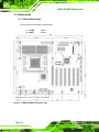
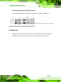
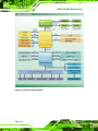
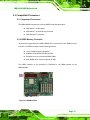


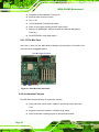

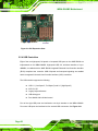

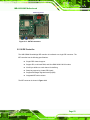
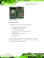
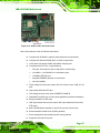


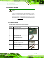
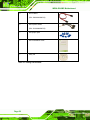

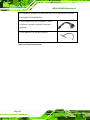

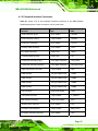
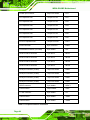


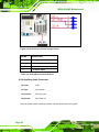
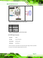
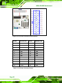

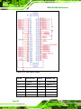
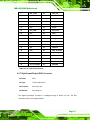

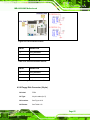
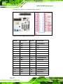
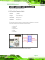
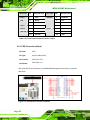

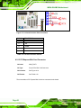


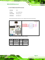


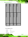


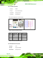
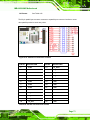


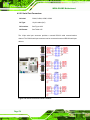
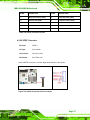
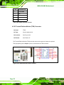
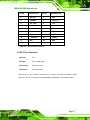
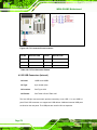


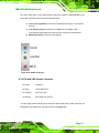

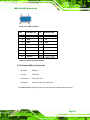
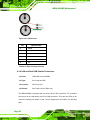
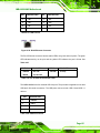


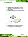
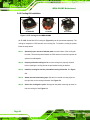


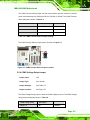

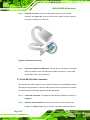
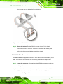


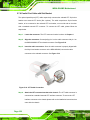


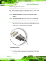
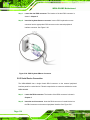
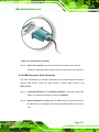


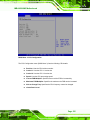


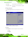


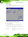
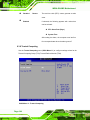
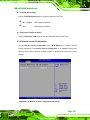


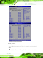


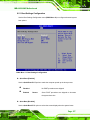
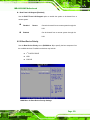


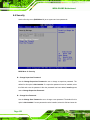

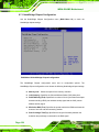


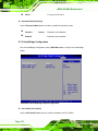


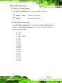
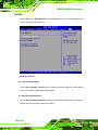


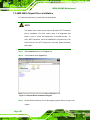
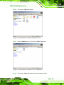
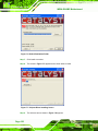
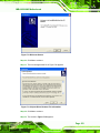
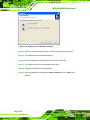
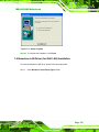

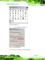


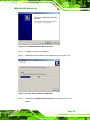
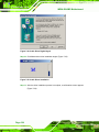

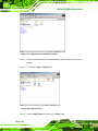
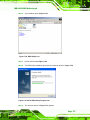
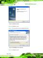
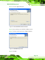
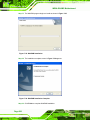

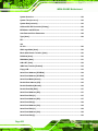

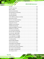


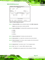
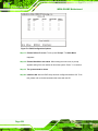

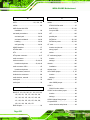
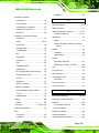


![[SPT-3000] e](http://vs1.manualzilla.com/store/data/005667089_1-a5f3766b3193f6552f250995926a69c5-150x150.png)