1
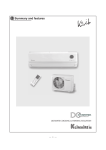
User’s Manual
MINIATURE SIGNAL RELAY
FUNCTIONS AND NOTES ON CORRECT USE
••
•
All specifications in this catalog and production status of products are subject to change without notice. Prior to the purchase, please contact NEC Tokin for updated product data.
Please request for a specification sheet for detailed product data prior to the purchase.
Before using the product in this catalog, please read “Precautions” and other safety precautions listed in the printed version catalog.
2006.03.24 P0159EMDD03VOL01E
The information in this document is based on documents issued in March, 2006 at the latest.
The information is subject to change without notice. For actual design-in refer to the latest publications
of data sheet, etc., for the most up-date specifications of the device.
No part of this document may be copied or reproduced in any form or by any means without the
prior written consent of NEC/TOKIN Corporation. NEC/TOKIN Corporation assumes no responsibility
for any errors which may appear in this document.
NEC/TOKIN Corporation does not assume any liability for infringement of patents, copyrights or
other intellectual property rights of third parties by or arising from use of a device described herein
or any other liability arising from use of such device. No license, either express, implied or
otherwise, is granted under any patents, copyrights or other intellectual property rights of NEC
/TOKIN Corporation or others.
While NEC/TOKIN Corporation has been making continuous effort to enhance the reliability of its
e l e c t r o n i c components, the possibility of defects cannot be eliminated entirely. To minimize risks
of damage or injury to persons or property arising from a defect in an NEC/TOKIN electronic component,
customers must incorporate sufficient safety measures in its design, such as redundancy, firecontainment, and anti-failure features. NEC/TOKIN devices are classified into the following three
quality grades:
"Standard," "Special," and "Specific". The Specific quality grade applies only to devices
developed based on a customer designated "Quality assurance program" for a specific
a p p l i c a t i o n . T h e r e c o m m e n d e d applications of a device depend on its quality grade, as indicated
below. Customers must check the quality grade of each device before using it in a particular
application.
Standard: Computers, office equipment, communications equipment, test and measurement
equipment, audio and visual equipment, home electronic appliances, machine tools,
personal electronic equipment and industrial robots
Special:
Transportation equipment (automobiles, trains, ships, etc.), traffic control systems,
anti-disaster systems, anti-crime systems, safety equipment and medical
e q u i p m e n t ( n o t specifically designed for life support)
Specific: Aircrafts, aerospace equipment, submersible repeaters, nuclear reactor control
s y s t e m s , l i f e support systems or medical equipment for life support, etc.
The quality grade of NEC/TOKIN devices is "Standard" unless otherwise specified in NEC/TOKIN's
Data Sheets or Data Books. If customers intend to use NEC/TOKIN devices for applications other
than those specified for Standard quality grade, they should contact an NEC/TOKIN sales representative
in advance.
(Note)
(1) "NEC/TOKIN" as used in this statement means NEC/TOKIN Corporation and also includes
its majority-owned subsidiaries.
( 2 ) "NEC/TOKIN electronic component products" means any electronic component product developed
or manufactured by or for NEC/TOKIN (as defined above).
DE0102
2
••
•
All specifications in this catalog and production status of products are subject to change without notice. Prior to the purchase, please contact NEC Tokin for updated product data.
Please request for a specification sheet for detailed product data prior to the purchase.
Before using the product in this catalog, please read “Precautions” and other safety precautions listed in the printed version catalog.
2006.03.24 P0159EMDD03VOL01E
CONTENTS
1. INTRODUCTION .............................................................................................................................. 5
2. PRODUCT CODE LEGEND ........................................................................................................... 6
3. CLASSIFICATION OF NEC’s MINIATURE RELAYS .................................................................... 7
3.1 General Classification .............................................................................................................................
7
3.2 Operational Functions ............................................................................................................................
7
3.3 Contact Arrangement .............................................................................................................................. 10
3.4 Contact Material ....................................................................................................................................... 12
4. NOTES ON CORRECT USE ........................................................................................................... 13
4.1 General ...................................................................................................................................................... 13
4.2 Connecting Contact Load
(Minimum Load, Contact Protection Circuit) ....................................................................................... 13
4.3 Driving Relays
(Ambient Temperature, Maximum Applied Voltage, Hot Start, Latching Relay, Drive Waveform,
Non-operation and Holding Voltages) ................................................................................................... 18
4.4 Environments
(Ambient Temperature, Humidity, Atmosphere, Atmospheric Pressure, Vibration and Shock,
Influence of Magnetic Fields) ................................................................................................................. 23
4.5 Influence of Relay Operation on Surroundings
(Electromagnetic Noise, Arc Discharge, Generation of Leakage Magnetic Flux) .......................... 25
4.6 Mounting
(Design of Printed Circuit Boards, Relay Mounting Position, Mounting) ........................................ 25
4.7 Cleaning
(Cleaning Solvent, Avoid Ultrasonic Cleaning) ................................................................................... 27
4.8 Handling Relays
(Use of Magazine Case Stoppers, Dropped Relay) ............................................................................. 27
4.9 Using Surface Mount Relays
(Mounting Pad, Glue Pads, Solder Reflow ) ......................................................................................... 28
5. ELECTRICAL CHARACTERISTICS MEASUREMENT
(Contact Resistance, Operate Voltage, Time Characteristics, Insulation Resistance,
Breakdown Voltage) ....................................................................................................................... 30
6. TERMINOLOGY .............................................................................................................................. 33
6.1 Terms Related to Standards ................................................................................................................... 33
6.2 Supplements ............................................................................................................................................. 36
3
••
•
All specifications in this catalog and production status of products are subject to change without notice. Prior to the purchase, please contact NEC Tokin for updated product data.
Please request for a specification sheet for detailed product data prior to the purchase.
Before using the product in this catalog, please read “Precautions” and other safety precautions listed in the printed version catalog.
2006.03.24 P0159EMDD03VOL01E
[MEMO]
4
••
•
All specifications in this catalog and production status of products are subject to change without notice. Prior to the purchase, please contact NEC Tokin for updated product data.
Please request for a specification sheet for detailed product data prior to the purchase.
Before using the product in this catalog, please read “Precautions” and other safety precautions listed in the printed version catalog.
2006.03.24 P0159EMDD03VOL01E
1. INTRODUCTION
Miniature signal relays are widely used in the fields of communications, measurement, and factory automation.
This document describes the functions of the NEC’s miniature signal relay and points to be noted when using the
relay. Reading both this document and the Data Sheet of each product is recommended when using a relay.
For further information, consult NEC.
Proper functioning of the miniature signal relay requires appropriate circuit design, mounting and evaluation
according to the purpose of use.
Note that the responsibility for accidents caused by improper circuit design, mounting or evaluation falls on you
and we cannot be reponsible for them.
5
••
•
All specifications in this catalog and production status of products are subject to change without notice. Prior to the purchase, please contact NEC Tokin for updated product data.
Please request for a specification sheet for detailed product data prior to the purchase.
Before using the product in this catalog, please read “Precautions” and other safety precautions listed in the printed version catalog.
2006.03.24 P0159EMDD03VOL01E
2. PRODUCT CODE LEGEND
NEC offers small, new, and ultra small type miniature signal relays. The product names of these relays consist
of codes indicating the function of each relay.
EA2-3 S N U
Option
Latch type:
None: Non-latch ty pe
S: Single-coil latch type
T: Double-coil latch type
Nominal coil voltage: Value of nominal coil voltage
Series name
6
••
•
All specifications in this catalog and production status of products are subject to change without notice. Prior to the purchase, please contact NEC Tokin for updated product data.
Please request for a specification sheet for detailed product data prior to the purchase.
Before using the product in this catalog, please read “Precautions” and other safety precautions listed in the printed version catalog.
2006.03.24 P0159EMDD03VOL01E
3. CLASSIFICATION OF NEC’s MINIATURE RELAYS
3.1 General Classification
NEC’s miniature signal relays are classified as follows:
Electromechanical relay
Miniature relay
Miniature signal relay
Miniature power relay
Sealed contact relay
Reed relay
Mercury reed relay
Solid-state relay
Figure 1 Classification of Relays
3.2 Operational Functions
This section describes the operations of the coil, which is the input section of a relay, and the contacts, which
constitute the output section.
Generally, when a current flows through the coil of a relay, the contacts operate. The contacts of an ordinary relay
release when a current ceases to flow through the coil. With some relays, however, contacts, once they have operated,
remain “set” and do not return to the original state even after the current supplied to the coil is removed. These relays
are called latching relays.
(Incidentally, the former type of relay is called a non-latch type or current holding type.)
The latching relay is further divided into two types by classification of coil: single coil latch type which has only
one coil, and double coil latch type, which has two coils.
(1) Relay operation
Figures. 2.1 through 2.3 illustrate the operations of the three types of relays mentioned above by using timing
charts.
1 Non-latch type (current holding type)
Energized
Coil
Not energized
Operate
Contacts
Release
Figure 2.1 Timing Chart of Non-Latch Type
2 Single coil latch type
Energized
+
Coil
Not energized
0
Energized
–
Set
Contacts
Reset
Figure 2.2 Timing Chart of Single Coil Latch Type
7
••
•
All specifications in this catalog and production status of products are subject to change without notice. Prior to the purchase, please contact NEC Tokin for updated product data.
Please request for a specification sheet for detailed product data prior to the purchase.
Before using the product in this catalog, please read “Precautions” and other safety precautions listed in the printed version catalog.
2006.03.24 P0159EMDD03VOL01E
3 Double coil latch type
Energized
+
Set
Coil
Not energized
0
+
Reset
Coil
Energized
Not energized
0
Set
Contacts
Reset
Figure 2.3 Timing Chart of Double Coil Latch Type
As illustrated in these figures, the contacts of a latching relay remain in the operate state even after an input
to the coil has been removed. Therefore, this relay plays the role of a memory circuit. Moreover, the latching
relay helps reduce the power dissipation in the application circuit because the coil needs not to be energized
all the time.
(2) Internal connections
The internal connections of the three types of relays are described below using NEC’s representative model,
EA2 series, as an example.
When connecting coils, refer to the wiring diagram to prevent mis-operation or malfunction.
1 Non-latch type
Figure 3.1 (a) shows the state where no current flows through the coil. When voltage is applied to the pole
shown in Figure 3.1 (b), the contacts operate.
–
–
+
+
(a) Not energized
(b) Energized
Figure 3.1 Non-Latch Type Operation
8
••
•
All specifications in this catalog and production status of products are subject to change without notice. Prior to the purchase, please contact NEC Tokin for updated product data.
Please request for a specification sheet for detailed product data prior to the purchase.
Before using the product in this catalog, please read “Precautions” and other safety precautions listed in the printed version catalog.
2006.03.24 P0159EMDD03VOL01E
2 Single coil latch type
When voltage of the polarity specified to set (S in figure 3.2 (a)) the coil is applied to the coil (in figure 3.2
(b)), the contacts operate. Even after the coil is deenergized, the contacts remain in the operate state (figure
3.2 (c)). When voltage of the polarity specified to reset (R) the coil is applied to the coil, the contacts release
(figure 3.2 (d)).
–
+
–
+
S
R
S
R
+
–
+
–
(a) Not energized (reset state)
(c)
(b) After voltage application (set state)
–
+
–
+
S
R
S
R
+
–
+
–
(c) Not energized (set state)
Return to (a)
(d) After voltage application (reset state)
Figure 3.2 Single Coil Latch Type Operations
3 Double coil latch type
As shown in figure 3.3 (a) through (d), the double coil latch type relay has two separate coils each of which
operates (sets) and releases (resets) the contacts.
R
+
–
R
+
–
(c)
S
–
+
(a) Not energized (reset state)
R
+
S
–
+
(b) After voltage applied to set coil (set state)
–
R
+
–
Returns to (a)
S
–
+
(c) Not energized (set state)
S
+
–
(d) After voltage applied to reset coil (reset state)
Figure 3.3 Double Coil Latch Type Operations
9
••
•
All specifications in this catalog and production status of products are subject to change without notice. Prior to the purchase, please contact NEC Tokin for updated product data.
Please request for a specification sheet for detailed product data prior to the purchase.
Before using the product in this catalog, please read “Precautions” and other safety precautions listed in the printed version catalog.
2006.03.24 P0159EMDD03VOL01E
3.3 Contact Arrangement
The contacts of the NEC’s miniature signal relays are divided into two types: transfer contacts and continuous
contacts.
Figure 4 shows the operation state of each type of contact.
Break
contact
Make
contact
Break
contact
Make
contact
Break
contact
Make
contact
Transfer
contacts
Common
contact
Common
contact
Before operation
Break
contact
Common
contact
During operation
Make
contact
Break
contact
After operation
Make
contact
Break
contact
Make
contact
Continuous
contacts
Common
contact
Common
contact
Common
contact
During operation
Before operation
After operation
Figure 4 Operation States of Each Contact
(1) Functions of transfer contacts
The common contact of the transfer contacts touches the make contact after it has been separated from the
break contact when the relay operates. When the relay releases, the common contact is separated from the
make contact and comes in contact with the break contact. Therefore, when the relay operates, there is a time
during which the common contact is not in contact with either make or break contacts (transfer time). For this
reason, the transfer contacts may also be referred to as “break-before-make” (BBM) contacts. These operations
are illustrated in the timing chart below.
Energized
Coil voltage
Not energized
Break contact
ON
OFF
Make contact
ON
OFF
Release time
Operate time
Bounce time
Transfer time
Bounce time
Transfer time
Figure 5.1 Timing Chart of Transfer Contacts
10
••
•
All specifications in this catalog and production status of products are subject to change without notice. Prior to the purchase, please contact NEC Tokin for updated product data.
Please request for a specification sheet for detailed product data prior to the purchase.
Before using the product in this catalog, please read “Precautions” and other safety precautions listed in the printed version catalog.
2006.03.24 P0159EMDD03VOL01E
1 The operate time is the time during which the make contact comes in contact with the common contact (ON
state) after the coil has been energized. This operate time includes the transfer time during which the common
contact is not in contact with either the make or the break contacts. The transfer time of the NEC’s miniature
signal relay is several 100 µs.
2 An electromechanical relay such as a miniature signal relay has a bounce time until the contacts are
completely closed. This bounce time of the NEC’s miniature signal relay is several 100 µs to several ms.
3 Similarly, when the relay is released, and therefore, when the common contact is separated from the make
contact and comes in contact with the break contact, transfer time and bounce time exist. The values of
these times are same as those when the relay operates.
A relay of this contact arrangement is used to switch over between two circuits and to completely set one circuit
free from the influences of the other circuit.
(2) Functions of continuous contacts
The common contact of the continuous contacts may come in contact with both the make and break contacts
(continuous time). This is illustrated by the timing chart in figure 5.2.
Energized
Coil voltage
Not energized
Break contact
ON
OFF
Make contact
ON
OFF
Bounce time
Bounce time
Release time
Operate time
Continuous state
Continuous time
Continuous time
Figure 5.2 Timing Chart of Continuous Contacts
As shown in this timing chart, the common contact comes in contact with the make contact before the break
contact is opened. For this reason, the continuous contacts may also be referred to as “make-before-break (MBB)
contacts”.
11
••
•
All specifications in this catalog and production status of products are subject to change without notice. Prior to the purchase, please contact NEC Tokin for updated product data.
Please request for a specification sheet for detailed product data prior to the purchase.
Before using the product in this catalog, please read “Precautions” and other safety precautions listed in the printed version catalog.
2006.03.24 P0159EMDD03VOL01E
A relay of this contact arrangement is used to continuously switch over from circuit A to B as shown in figure
6, where, when viewed from the power source, there is a little deenergized state and the two circuits are
instantaneously connected in parallel.
1
2
3
1 Before operation
Break contact
Make contact
2 During operation
Circuit A
Power source
Figure 6
Circuit B
3 After operation
Example of Use of Continuous Contacts
3.4 Contact Material
The contacts of the NEC’s miniature signal relay is made of a silver-nickel alloy (AgNi) in the case of the generalpurpose model. The base metal of the contacts of the high-reliability model is silver-palladium alloy (AgPd).
The silver-nickel alloy has a low contact resistance and an excellent mechanical durability. The silver-palladium
alloy is highly resistant to corrosion, and is employed for applications where high contact reliability is required.
The gold alloy is coated on these silver alloys as a contact surface to further improve the reliability.
The ultrasonic cleaning type employs sliver radium for the moving break contact and gold for the stationary contact.
By employing different metals like this, immunity to adhesion due to external vibration is improved.
Movable contact
Gold alloy overlay
Base metal
Stationary contact
Base
Normal type
Ultrasonic cleaning type
Figure 7 Cross-Sectional View of a Contact
12
••
•
All specifications in this catalog and production status of products are subject to change without notice. Prior to the purchase, please contact NEC Tokin for updated product data.
Please request for a specification sheet for detailed product data prior to the purchase.
Before using the product in this catalog, please read “Precautions” and other safety precautions listed in the printed version catalog.
2006.03.24 P0159EMDD03VOL01E
4. NOTES ON CORRECT USE
4.1 General
(1) Never allow the contact load to exceed the maximum ratings; otherwise, the lifetime of the relay will be dramatically
shortened.
The lifetime specified in the catalog is for certain load conditions, and other factors must be taken into
consideration in actual circuits. Therefore, an accurate lifetime must be measured in the actual circuit.
The table below shows load current range guideline.
Current range
100 µA to 1mA
1mA to 0.5A
0.5A to 2A
GOOD
VERY GOOD
NOT SO GOOD
for some cases
• Contacts may be
unstable.
• Thermal electroApplication
• Contacts are
• Infrequent
stable and highly
operation poses
reliable.
no problem, but
motive force and
frequent operation
contact noise
deteriorates
should be taken
into consideration.
contact stability.
• Use of a power
relay is preferred
for 1 A or higher.
(2) When using the relay with a high current or high capacitance load, an inrush current may cause contact dislocation
or deposition; therefore check the feasibility of use in the actual circuit.
(3) Be sure to use the relay at an ambient temperature within the maximum ratings; otherwise, the life of the relay
will be radically shortened. If use outside the specified temperature range in unavoidable, consult NEC.
(4) With a relay whose coil polarity is specified in its internal circuit diagram, apply the polarity of the rated voltage
as specified. Note that when a rippled DC power source is used, abnormalities such as beat in the coil may occur.
(5) Exercise care when handling the relay so as not to apply shock to it or drop it.
(6) The flow soldering conditions are for 5 to 10 seconds at 250°C.
(7) When cleaning, use alcohol, or a water-based solvent. Avoid using ultrasonic cleaning. If it is necessary to use
ultrasonic cleaning, use a product resistant to such cleaning.
(8) Sonic noise may occur during the relay operation. Depending on the mounting position, the sonic noise may
sound intolerable, so be sure to check the mounting position thoroughly prior to use.
4.2 Connecting Contact Load
(1) Minimum load
Use the relay at a voltage and current higher than the minimum load; otherwise, the contact resistance will
increase and signal cannot be correctly transmitted. In addition, self-cleaning effect, which electrically and
mechanically eliminates minute substances generated on the contact surface when the contacts are opened and
closed, cannot be expected.
13
••
•
All specifications in this catalog and production status of products are subject to change without notice. Prior to the purchase, please contact NEC Tokin for updated product data.
Please request for a specification sheet for detailed product data prior to the purchase.
Before using the product in this catalog, please read “Precautions” and other safety precautions listed in the printed version catalog.
2006.03.24 P0159EMDD03VOL01E
(2) Contact protection circuit
By providing a protection circuit that suppresses transient current and voltage applied to the contacts when the
contacts are opened or closed, the switching life of a relay can be improved.
The applicable protection circuit differs depending on the load type of the contacts.
1 Protection circuit classified by load type
(a) Inductive load
With an inductive load, when the contacts are opened to break the circuit, a counter electromotive force
is generated. This voltage causes arc discharge between the contacts. The charged energy accelerates
metal deposition and wear on the contact surface.
A protection circuit is therefore used to absorb the counter electromotive force.
V
V
Contacts
open
E
E
Inductive load
Time
Figure 8 Inductive Load Circuit
14
••
•
All specifications in this catalog and production status of products are subject to change without notice. Prior to the purchase, please contact NEC Tokin for updated product data.
Please request for a specification sheet for detailed product data prior to the purchase.
Before using the product in this catalog, please read “Precautions” and other safety precautions listed in the printed version catalog.
2006.03.24 P0159EMDD03VOL01E
Table 1 shows examples of protection circuits.
Table 1 Inductive Load Contact Protection Circuit
Protection element
Remarks
Circuit example
r(Ω) =
Inductive load
Capacitor
r
c
contact voltage (V)
0.5 to 1
c(µF) = (0.5 to 1)
× contact current (A)
+
resistor
(CR circuit)
Non breakdown voltage of a
r
Inductive load
non-polar capacitor should be
300 V or higher.
c
Varistor
Inductive load
High voltage is suppressed by
using the voltage characteristics of the varistor.
Pay attention to the reverse
Diode
Inductive load
Diode + Zener diode
Inductive load
breakdown voltage of the
diode.
The ON time of the diode is
controlled by using the Zener
voltage characteristic and the
recovery time of the relay can
be shortened.
15
••
•
All specifications in this catalog and production status of products are subject to change without notice. Prior to the purchase, please contact NEC Tokin for updated product data.
Please request for a specification sheet for detailed product data prior to the purchase.
Before using the product in this catalog, please read “Precautions” and other safety precautions listed in the printed version catalog.
2006.03.24 P0159EMDD03VOL01E
(b) Capacitive load
Never use a connection with a capacitor only as shown in table 2.
Table 2 Examples of Wrong Circuits Using Capacitiors
This circuit is effective for
WRONG
c
WRONG
This circuit is effective for
arc suppression when the
arc suppression when the
contacts are opened, but
contacts are opened, but
when the contacts are
when the contacts are
closed a capacitor shortLoad
circuit current flows,
c
Load
closed a capacitor charging current flows, making
making the contacts more
the contacts more suscep-
susceptible to metal
tible to metal deposition.
deposition.
(c) Loads of lamps and the like (inrush current)
Some loads, such as tungsten lamps, have a low initial resistance so that an inrush current of 10 times
as high as the steady-state current may flow through the relay on power application. A high inrush current
may also flow when the relay is used to switch loads such as motors, capacitors, and electromagnetic
solenoids. In these cases, it is necessary to keep the current to within the maximum rated value.
Therefore, a current-limiting resistor is connected to the contacts in series.
Without current-limiting resistor
Current
With current-limiting resistor
Contacts
Lamp
0
Power source
Time
Figure 9 Inrush Current of Loads from Lamps and the Like
16
••
•
All specifications in this catalog and production status of products are subject to change without notice. Prior to the purchase, please contact NEC Tokin for updated product data.
Please request for a specification sheet for detailed product data prior to the purchase.
Before using the product in this catalog, please read “Precautions” and other safety precautions listed in the printed version catalog.
2006.03.24 P0159EMDD03VOL01E
(d) Load with large stray capacitance
If the wiring length of a circuit where a relay is used is long, an inrush current that is generated due to
a stray capacitance poses a problem.
As shown in figure 10, the electric energy charged to the line capacitance is discharged directly through
the contacts when the contacts are closed (ON). Generally, the stray capacitance must be taken into
consideration if the wiring length reaches several tens of meters.
In this case, a current-limiting resistor or surge suppressor coil is connected in series to the contacts
to suppress the peak current.
Surge suppressor coil
Contacts
Power source
Load
Wiring cable
Figure 10 Stray Capacitance
17
••
•
All specifications in this catalog and production status of products are subject to change without notice. Prior to the purchase, please contact NEC Tokin for updated product data.
Please request for a specification sheet for detailed product data prior to the purchase.
Before using the product in this catalog, please read “Precautions” and other safety precautions listed in the printed version catalog.
2006.03.24 P0159EMDD03VOL01E
4.3 Driving Relays
This section describes points to be noted when driving a relay.
(1) Ambient temperature
When an NEC’s relay is used at an ambient temperature exceeding or falling below the range set forth in the
catalog, the performance of the relay may be degraded and the life may be extremely shortened.
1 Generally, use the relay in the specified temperature range at less than the maximum ratings. Note, however,
that the maximum must operate voltage of the coil changes with temperature, and must be confirmed before
the relay is used (refer to (2) in “Maximum applied voltage”).
2 The operating characteristics of the relay change with ambient temperature (refer to figure 11 below). Confirm
the temperature condition in the application set where the relay is to be used.
For the temperature
130
120
Must operate
Must release
Changes in operate and
release time (%)
Changes in must operate and must
release voltages (%)
characteristics of a relay, refer to Technical Documents.
110
100
90
80
70
–40 –20
0
20
40
60
Operate
Release
130
120
110
100
90
80
70
80 100
–40 –20
Ambient temperature Ta (°C)
0
20
40
60
80 100
Ambient temperature Ta (°C)
Figure 11 Temperature Characteristics of Relay (Example)
(2) Maximum applied voltage
The coil of a relay generates heat when it is energized; therefore, the temperature which is the difference between
the designed maximum temperature of the relay and the ambient temperature is the permissible maximum heat
temperature (voltage).
Refer to the coil voltage vs. temperature derating characteristics in the catalog.
The designed maximum temperature is determined mainly by the coil wire materials and the permissible
temperature of plastic materials.
The coil wire of the NEC’s miniature signal relay is a polyurethane copper wire, which is Type E of JIS-C4003
Maximum applied voltage to coil
(ratio to rated voltage) (%)
and whose permissible temperature is 120°C.
Derating factor : 50% per 45°C
150
100
85°C
–40
–20
0
20
40
60
80
100
Ambient temperature Ta (°C)
Figure 12 Coil Voltage vs Temperature Derating Characteristics (Example)
18
••
•
All specifications in this catalog and production status of products are subject to change without notice. Prior to the purchase, please contact NEC Tokin for updated product data.
Please request for a specification sheet for detailed product data prior to the purchase.
Before using the product in this catalog, please read “Precautions” and other safety precautions listed in the printed version catalog.
2006.03.24 P0159EMDD03VOL01E
(3) Hot start
When the temperature of a relay has risen due to heat generated when the relay has been energized, the relay
may not operate even if the coil is energized again immediately after it has been deenergized once. This is
because the coil resistance has increased when it has been energized the first time. Consequently, to reoperate
the relay, an increased voltage must be applied.
This state is called hot start. When the relay is used in a location where ambient temperature is high, or if the
rated voltage of the relay cannot be applied, appropriate countermeasures must be taken against a hot start.
For the hot start voltage to operate the relay, refer to the Technical Documents of each product.
(4) Non-operation and holding voltages
In an application circuit of a relay, the relay must not operate or release at a certain voltage. In this case, the
non-operation and holding voltages of the relay must be known. To do so, confirm the variations of the operate
voltage and release voltage of the relay with NEC’s Technical Documents and other documents.
If the necessary holding voltage and non-operation voltage cannot be secured because of variations of the relay,
Degree of distribution
special specification models are readily available from NEC.
Must operate
voltage
Must release
voltage
0
Must release
voltage (rated)
Holding
voltage
Non-must
operate voltage
Must operate
voltage (rated)
Rated
voltage
Figure 13 Example of Distribution of Relay Operate Voltage
(5) Drive waveform
It is not desirable that the waveform of the voltage applied to a relay coil gradually increase and decrease. The
voltage must instantaneously rise and fall as a pulse.
If the voltage gradually increases and decreases, the relay does not perform its snap action, and its fullest
performance cannot be attained.
Correct
Pulse
Incorrect (avoid)
Non-pulse
Figure 14 Relay Drive Waveform
19
••
•
All specifications in this catalog and production status of products are subject to change without notice. Prior to the purchase, please contact NEC Tokin for updated product data.
Please request for a specification sheet for detailed product data prior to the purchase.
Before using the product in this catalog, please read “Precautions” and other safety precautions listed in the printed version catalog.
2006.03.24 P0159EMDD03VOL01E
(6) Drive circuit (latching relay)
The drive circuit of a latching relay is especially important. Therefore, special attention needs to be paid to the
drive circuit of a latching relay in this section.
1 Since the coil of a relay has an inductive impedance, a counter electromotive force is generated when the
circuit is opened. This voltage may damage the relay driver IC. Therefore, with a double coil latch type current
holding relay, a diode is connected in parallel with each coil, as shown in figure 13. With a single coil latching
type relay, however, a diode cannot be used because the current direction of the coil is inverted.
Therefore, the driver circuit of this relay must be designed and confirmed in the actual circuit.
Set coil
Reset coil
+
+
–
–
Set pulse
Reset pulse
Figure 15 Drive Circuit of Latching Relay (Example)
2 A latching relay is driven by a pulsating coil voltage. The pulse width of this drive voltage must be 10 ms
or wider. If the pulse is too short, the relay may not operate.
3 Apply a voltage to the coil in the polarity specified by the internal connection diagram of the relay. With a
double coil latching type relay, do not apply voltage in a manner that both the set and reset coils are energized
at the same time.
4 A latching relay is factory-set to the reset state for shipment. However, it may be set while being transported
due to vibration or shock.
Make sure that the relay is reset when its application system starts operating. When the relay is employed
in a portable system, the circuit must be designed so that the relay is reset at the beginning of the operation
of the system because the relay may be set by unexpected vibration or shock.
5 Whe configuring a self-holding circuit that uses the self break contacts of the relay, note that the coil drive
circuit is disconnected by the self-contacts, causing problems such as self oscillation.
(7) Connection of coil diode
In the case of loads, such as solenoid and electromagnetic clutches, that produce large discharge energy when
the contacts are opened, connect a Zener diode on the drive transistor side. Particularly, if the diode is connected
to the coil in parallel, the counter electromotive force of the coil returns the current gradually when the relay is
released, and thus may slow down the opening of the contacts, intensifying wear on the contacts.
(8) Opening/closing frequency
If the contacts are opened/closed frequently with a high current load, repeated electric discharges may cause
contact metal deposition or damage to the contact spring.When using the relay with a high current load with
frequent opening/closing of the contacts, consult NEC.
20
••
•
All specifications in this catalog and production status of products are subject to change without notice. Prior to the purchase, please contact NEC Tokin for updated product data.
Please request for a specification sheet for detailed product data prior to the purchase.
Before using the product in this catalog, please read “Precautions” and other safety precautions listed in the printed version catalog.
2006.03.24 P0159EMDD03VOL01E
(9) Long continuous energizing of coil
If the coil is energized continuously for a long time, the coil temperature may rise, promoting generation of organic
gas inside the relay, which is likely to cause trouble in the contacts. When using a circuit requiring constant
operation, consider the possibility of using a latching relay that does not need continuous energizing of the coil.
(10) Instantaneous voltage drop of circuit
When the same power source is used for the relay drive circuit and the load circuit in a circuit such as a
lamp load circuit where an inrush current flows, the moment the contacts are closed the source voltage may
drop if the power source capacitance is small. In this case, the relay may be released or an oscillation
phenomenon where the relay repeatedly releases and operates may occur.
Add power source capacitance or a smoothing circuit to prevent this phenomenon.
(11) Malfunctioning due to unwanted voltage
Because the miniature signal relay is designed to be highly sensitive, it may operate by mistake if a pulsating
noise whose pulse width is shorter than the normal drive voltage is applied to the coil for a short time.
Therefore, exercise care that such an unwanted voltage is not applied to the coil.
The device recovers from this phenomenon after the coil voltage has been removed, and then contacts have
operated, as shown in the timing chart in figure 16.
The relationship between the magnitude of the coil voltage that causes the above phenomenon and the pulse
width is similar to that illustrated below, however, this should be confirmed with the actual circuit.
(Timing chart of unwanted voltage)
(Relation between pulse time width and coil voltage)
Pulse time width (ms)
1.0
Coil voltage
0.5
Pulse time
0
Contacts operate
Recovery
Operate
Recovery
90
100
110
Ratio of rated coil voltage (%)
Figure 16 Malfunctioning due to Unwanted Voltage
21
••
•
All specifications in this catalog and production status of products are subject to change without notice. Prior to the purchase, please contact NEC Tokin for updated product data.
Please request for a specification sheet for detailed product data prior to the purchase.
Before using the product in this catalog, please read “Precautions” and other safety precautions listed in the printed version catalog.
2006.03.24 P0159EMDD03VOL01E
(12) Momentary interception failure of continuous contacts
The continuous contacts are suitable for applications where two circuits must be changed over in a time shorter
than that of the transfer contacts because the continuous contacts are continuously switched. However, a
interception failure does occur in the application circuit because of the bounce of the contacts, and a thorough
evaluation must be made before the continuous contacts are actually used in an application.
Because the miniature signal relay has little bounce, the momentary power failure is kept to a relatively short
time. For details, consult NEC.
(Momentary interception failure evaluation circuit)
(Timing chart of momentary interception failure)
B
Power
supply
Energization
Current
measuring
resistor
R
M
Coil
voltage
0
Continuous
B
2R
M
Contact
current
(operating
status)
Recovery
Continuous
Operate
0
Note If a momentary power failure occurs, the voltage across the resistor is zero.
Figure 17 Momentary Power Failure of Continuous Contacts
22
••
•
All specifications in this catalog and production status of products are subject to change without notice. Prior to the purchase, please contact NEC Tokin for updated product data.
Please request for a specification sheet for detailed product data prior to the purchase.
Before using the product in this catalog, please read “Precautions” and other safety precautions listed in the printed version catalog.
2006.03.24 P0159EMDD03VOL01E
4.4 Environments
This section describes the environments where a relay should be used.
(1) Ambient temperature
Ensure that the ambient temperature of the relay mounted on the device is within the “operating temperature
range” in the catalog. Use of the relay at a temperature outside this range may adversely affect insulation or
contact performance. For the relationship between the ambient temperature and relay drive conditions, refer
to 4.3 NOTES ON DRIVING RELAYS.
(2) Humidity
Use of a sealed type relay in a high dumidity (RH85% or higher) environment for a long time may introduce
moisture inside the relay. This moisture may combine with NOx or SOx generated by glow dischanges to produce
nitric acid or sulfuric acid. In this case, the acid produced may corrode the metal that forms the relay, causing
operation troubles in the relay. If use of the relay in such a high humidity environment is unavoidable, consult
NEC in advance.
(3) Atmosphere
Use of a relay in an atmosphere with a high concentration of sulfur gases (H2S, SO2), nitric acid gas (HNO3),
ammonia (NH3), silicon vaporization gas, etc., may cause imperfect contacts and other functional trouble. Avoic
use of the relay in such an atmosphere. If it is unavoidable, use a sealed type relay.
(4) Atmospheric pressure
A sealed type relay maintains constant sealability under normal pressures (810 to 1200 hpa). However, if it is
used under other pressure conditions, its sealability may be destroyed or the relay may be deformed, causing
functional trouble. Be sure to use the relay under normal pressure conditions.
(5) Vibration and shock
The vibration resistance and shock resistance of a relay are as shown in the catalog and use of the relay under
conditions other than those specified may cause malfunctions or damage.
Be sure to use the relay within those vibration and shock conditions.
Note that operation of a snap switch mounted close to the relay or shock by operation of an electromagnet may
cause malfunctioning.
(6) Influence of magnetic fields
The magnetic circuit of an NEC miniature signal relay is constructed so that the relay does not easily malfunction
due to influence of external magnetic fields. However, under the influence of magnetic flux leaking from a
transformer, speaker, or magnet placed in the vicinity of the relay, the must operate voltage, must release voltage,
operate time, release time and other dynamix characteristics may change.
In applications where these characteristics changes pose problems, it is necessary to take measure such as
magnetic shielding. Also, when many make them miniature signal relays are closely located, the magnetic flux
leaking from those relays may make them interfere with each other, causing changes in the must operate voltage,
must release voltage, operate time, release time and other dynamic characteristics. Figure 9 shows examples
of the mounting, magnetization, and change in the must operate voltage of signal relays in the EA2 series. In
applications where these characteristics changes pose a problem, it is necessary to reduce the mounting density.
23
••
•
All specifications in this catalog and production status of products are subject to change without notice. Prior to the purchase, please contact NEC Tokin for updated product data.
Please request for a specification sheet for detailed product data prior to the purchase.
Before using the product in this catalog, please read “Precautions” and other safety precautions listed in the printed version catalog.
2006.03.24 P0159EMDD03VOL01E
Rate of change in must
operate voltage (%)
Changes in must operate voltage
50
40
30
20
10
0
–10
–20
–30
–40
–50
Set sample
Number of samples : 10 each
ON
ON
OFF
OFF
ON
OFF
ON
Maximum value
I
II
OFF
III
IV
Minimum value
I
II
III
IV
V
Mounting method
VI
ON
OFF
ON
OFF
ON
OFF
V
VI
Figure 18 Dense Mounting
24
••
•
All specifications in this catalog and production status of products are subject to change without notice. Prior to the purchase, please contact NEC Tokin for updated product data.
Please request for a specification sheet for detailed product data prior to the purchase.
Before using the product in this catalog, please read “Precautions” and other safety precautions listed in the printed version catalog.
2006.03.24 P0159EMDD03VOL01E
4.5 Influence of Relay Operation on Surroundings
(1) Electromagnetic noise
Switching the relay coil generates a high electromotive force due to induction. In general, a surge suppression
circuit is connected in parallel with the relay coil to suppress generation of this electromotive force. However,
if this suppression circuit is not appropriate, electronic circuits such as microcontrollers may malfunction due
to the surge generated. Add an appropriate absorption circuit to prevent electronic circuits from malfunctioning
due to the surge generated.
(2) Arc discharge
Connecting/disconnecting a high current at the relay contacts generates an arc discharge. This discharge may
cause electronic circuits such as microcontrollers to malfunction and therefore it is necessary to take appropriate
measures.
(3) Generation of leakage magnetic flux
Leakage magnetic flux exists in the vicinity of the relay in the magnetized state. Mounting a magnetic sensor,
etc. close to the relay may cause malfunctioning.
4.6 Mounting
(1) Design of printed circuit boards
1 If an electronic circuit such as a microcontroller is placed close to a relay, noise generated by the relay may
cause malfunctioning.
2 When designing patterns keep to the shortest possible distance in wiring.
3 For the printed circuit board on which a relay is mounted, use a board o 1 mm or more in thickness. If the
printed circuit board is not thick enough, it may be subject to warpage which will add tension to the relay,
causing variations in the relay characteristics. Because a flexible printed circuit borad is particularly thin,
it is necessary to solder near the root of the relay pins. Since preliminary soldering of the pin root part is
often insufficient, its solder is likely to become loose.
4 If a thermal cycle is applied to the soldered part, cracks may be generated in it. Special care is required
for the relay location, base material and through hole shape.
(2) Relay mounting position
The vibration resistance and shock resistance of a relay are greatly affected by its mounting position. It is
particularly important to select the mounting position to prevent the break contacts from being instantaneously
cut due to vibration and shock. The vibration resistance and shock resistance are at a minimum when the
direction of vibration and shock applied to the relay matches the operation direction of the armature (mobile iron
piece) and contacts. Therefore, if it is possible to anticipate the direction of vibration or shocks, mount the relay
so that the direction in which vibration of shocks are applied is perpendicular to the direction of the relay armature
operation figure 19 shows the direction of relay armature operation.
Figure 19 Direction of Armature Operation
25
••
•
All specifications in this catalog and production status of products are subject to change without notice. Prior to the purchase, please contact NEC Tokin for updated product data.
Please request for a specification sheet for detailed product data prior to the purchase.
Before using the product in this catalog, please read “Precautions” and other safety precautions listed in the printed version catalog.
2006.03.24 P0159EMDD03VOL01E
(3) Notes on mounting
1 Chucking
When a relay is mounted using an automatic machine, note that application of an excessive external force
to the cover at the time of chucking or insertion of the relay may damage or change the characteristics of
the cover.
2 Temporary securing to printed circuit board
Avoid bending the pins to temporarily secure the relay to the printed circuit board. (Refer to figure 20.)
Bending the pins may degrade sealability or adversely influence the internal mechanism. Pin bending may
be allowed under certain conditions in the case of miniature signal relays. Contact NEC for details.
Good example
Bad example
Figure 20 Bending Relay Pins
3 Soldering work
The following conditions are recommended for soldering a relay onto a printed circuit board.
(a) Automatic soldering: Flow solder is recommended.
<Recommended conditions> * Preheating: 100°C max. 1 min. max.
* Solder temperature: 250°C max.
* Solder time: 5 to 10 seconds
(b) Manual soldering (by soldering iron):
<Recommended conditions>
* Solder temperature: 350°C max.
* Solder time: 2 to 3 seconds
Ventilation immediately after soldering is completed is recommended.
Avoid immersing the board in cleaning solvent immediately after soldering; otherwise thermal shock may
be applied to it.
4 Pin cutting after soldering
Do not cut the pins of the relay with a revolving blade or an ultrasonic cutter, because vibration that is applied
to the relay during the cutting may change the relay characteristics.
26
••
•
All specifications in this catalog and production status of products are subject to change without notice. Prior to the purchase, please contact NEC Tokin for updated product data.
Please request for a specification sheet for detailed product data prior to the purchase.
Before using the product in this catalog, please read “Precautions” and other safety precautions listed in the printed version catalog.
2006.03.24 P0159EMDD03VOL01E
4.7 Cleaning
(1) Cleaning solvent
Use of alcohol or water-based cleaning solvents is recommended. Never use thinner or benzene because these
solvents may damage the relay housing. A sealed type relay can be immerse-cleaned because solvent does
not penetrate inside the relay.
(2) Avoid ultrasonic cleaning.
Ultrasonic cleaning may cause a break in the coil wire or sticking of the contacts due to the energy of vibration.
Use ultrasonic cleaning with only the models designed for it.
4.8 Handling Relays
(1) Use of magazine case stoppers
Relays are packaged in magazine cases for shipment.
When some relays are taken out from the case and space is freed inside the case, be sure to secure the relays
in the case with a stopper. If the relays are not well secured, vibration during transportation may cause contact
problems.
Stopper
Stopper
Push in to secure the relays.
Figure 21 Storage in Magazine Case
(2) Do not use relays that have been dropped.
If an individual relay product falls from the work table, etc. a shock of 1000 G or more is applied to the relay and
its functions may be destroyed. Even if the shock is apparently weak, confirm that there is no abnormality before
using the relay.
27
••
•
All specifications in this catalog and production status of products are subject to change without notice. Prior to the purchase, please contact NEC Tokin for updated product data.
Please request for a specification sheet for detailed product data prior to the purchase.
Before using the product in this catalog, please read “Precautions” and other safety precautions listed in the printed version catalog.
2006.03.24 P0159EMDD03VOL01E
4.9 Using Surface Mount Relays
This section describes specific points to be noted when using a surface mount relay. For common points for both
types, refer to the previous section.
(1) Mounting pad
Determine the dimensions of the mounting pads on a printed circuit board taking into consideration such factors
as solderability, insulation, and mounting variations of the automatic mounter.
Use the dimensions of the mounting pads set forth in the catalog of the relay for reference.
1.0
3.0
9.56
2.54
(Tolerance : ±0.1)
10.16
Figure 22 Dimensions of the Relay Mounting Pad (Example of EB2 Series)
28
••
•
All specifications in this catalog and production status of products are subject to change without notice. Prior to the purchase, please contact NEC Tokin for updated product data.
Please request for a specification sheet for detailed product data prior to the purchase.
Before using the product in this catalog, please read “Precautions” and other safety precautions listed in the printed version catalog.
2006.03.24 P0159EMDD03VOL01E
(2) Solder reflow
The surface mount relay is highly resistant to heat. However, solder the relay under the correct temperature
conditions so that the full performances of the relay can be attained.
IRS (infrared ray reflow soldering) and VPS (vapor phase soldering) methods are recommended.
In addition, air reflow soldering may be also used. Whichever soldering method is used, be sure to confirm the
temperature conditions for soldering and the influences of soldering on the relay in advance.
IRS
Temperature (°C)
Tmax.: 235
200
175
150
200 sec.
30 sec.
80 sec.
VPS
Temperature (°C)
Tmax. : 215
200°C max.
165°C max.
100°C max.
60 s max.
60 s
90 s max.
Figure 23 Solder Reflow Temperature Conditions (Example of EB2 Series)
(3) Long-term storage
Problems with airtightness may occur due to the solder heat after moisture absorption. Be sure to follow the
description below when storing the SMT relays.
(a) The storage humidity must be no more than 70% and the relay must be used within 3 months.
(b) When storing for more than 3 months, the storage humidity must be no more than 50% and the relay must
be used witthin 6 months.
29
••
•
All specifications in this catalog and production status of products are subject to change without notice. Prior to the purchase, please contact NEC Tokin for updated product data.
Please request for a specification sheet for detailed product data prior to the purchase.
Before using the product in this catalog, please read “Precautions” and other safety precautions listed in the printed version catalog.
2006.03.24 P0159EMDD03VOL01E
5. ELECTRICAL CHARACTERISTICS MEASUREMENT
This chapter describes some methods to measure the electrical characteristics of a relay.
The methods introduced here are examples. To conduct acceptance tests, consult NEC.
These measurement methods conform to JIS-C5442 (testing methods of small electromagnetic relays for control
applications).
(1) Contact resistance
1 The resistance between contacts when they are closed (ON) is measured by the voltage drop method.
Set the supply voltage (voltage between pins when the contacts are open) to 6 Vdc and the measurement
current to 1 A with controlling current limit resistance decreasingly.
As a simple method, use a low ohmmeter by Hewlette-Packard (HP-4338A).
2 To measure the resistance of the make contact, apply the rated voltage to the coil.
3 The contact resistance is the value including the conductor resistance of the pins.
Relay
A
V
Nominal
coil voltage
6 Vdc
Figure 24 Measuring Contact Resistance
(2) Operation voltages (must operate and must release voltages)
1 Apply a pulsating voltage to the coil and observe the contact state. To generate the coil voltage, use of a
programmable power supply is convenient.
To observe the contact state, apply the potential signal of the contacts to the input of the inverter and observe
changes in the output state (voltage drop when the contacts are closed, and supply voltage when the contacts
are open).
5V
Programmable
power supply
Relay
I/O
a
Inverter
Contact potential signal
Personal computer
(I/O port used)
Contact signal
Figure 25 Measuring Operation Voltages
30
••
•
All specifications in this catalog and production status of products are subject to change without notice. Prior to the purchase, please contact NEC Tokin for updated product data.
Please request for a specification sheet for detailed product data prior to the purchase.
Before using the product in this catalog, please read “Precautions” and other safety precautions listed in the printed version catalog.
2006.03.24 P0159EMDD03VOL01E
2 To measure the must operation voltage, gradually increase the pulse voltage applied to the coil. To measure
the must release voltage, decrease the coil voltage stepwise from the rated voltage to a certain value.
3 If a pulsating voltage cannot be obtained easily, use a slope voltage. In this case, however, the measured
value will not be accurate.
Voltage
Rating
(Pulse)
Must operate
Must release
0
Time
Voltage
Rating
Must operate
(Slope)
Must release
0
Time
Figure 26 Measuring Waveform of Operation Voltage (Coil Voltage)
(3) Time characteristics (operate time and release time)
1 Apply a pulse voltage to the coil and measure the time difference required for the contacts to change their
states.
2 A single pulse with a pulse width of 10 ms is the best as the coil voltage. However, a repetitive pulse at
about 10 Hz can also be used.
To observe the contact state, connect a load of 5 V, 10 mA and use an oscilloscope.
3 The time characteristics of the non-latch type (current hold type) relay can be measured with the following
circuit. Apply voltage in both the positive and negative directions to the single coil latch type relay. With
the double coil latch type, apply voltage to the set and reset coils alternately.
Load
resistance
Pulse generator, etc.
Load voltage
Oscilloscope
Figure 27 Measuring Time Characteristics
31
••
•
All specifications in this catalog and production status of products are subject to change without notice. Prior to the purchase, please contact NEC Tokin for updated product data.
Please request for a specification sheet for detailed product data prior to the purchase.
Before using the product in this catalog, please read “Precautions” and other safety precautions listed in the printed version catalog.
2006.03.24 P0159EMDD03VOL01E
(4) Insulation resistance
1 Measure the electric resistance between insulated conductors with a megohmmeter.
The measurement voltage is 500 Vdc.
The measured value changes with ambient temperature (the insulation resistance decreases as the
temperature rises). Measure under standard conditions (temperature: 5 to 35°C, relative humidity: 60 ± 15%).
2 Measure the insulation resistance at the following relay pins:
(a) Between opposing contacts (with the make contact not energized, and the break contact energized)
(b) Between adjacent contacts
(c) Between coil and contact
(d) Between two coils of double coil latch type (between set coil and reset coil)
(e) Between ground pin and contact pin and between ground pin and coil pin with a relay with a ground pin
(5) Breakdown voltage
1 Apply a surge voltage or AC voltage between insulated conductors and confirm that breakdown does not
occur.
2 Use a breakdown voltage tester and apply the specified voltage to the sample for 1 minute.
Set the detection break current (that detects breakdown and protect the sample from damages) to 1 mA.
According to JIS, a test in which 110% of the specified voltage is applied to the sample for 1 second can
be used instead if there is no problem for measurement.
3 Measure the breakdown voltage at the same pins as those at which the insulation resistance is measured.
32
••
•
All specifications in this catalog and production status of products are subject to change without notice. Prior to the purchase, please contact NEC Tokin for updated product data.
Please request for a specification sheet for detailed product data prior to the purchase.
Before using the product in this catalog, please read “Precautions” and other safety precautions listed in the printed version catalog.
2006.03.24 P0159EMDD03VOL01E
6. TERMINOLOGY
This chapter describes the major technical terms set forth in the Data Sheet, and related manuals.
6.1 Terms Related to Standards
The terms used in NEC’s catalogs in connection with standards and performances are as follows:
Nominal coil voltage
A standard voltage applied to the coil to use the relay.
Coil resistance
DC resistance of the coil. Usually measured at 25°C.
A tolerance of ±10% usually applies.
Maximum coil voltage
The maximum voltage that can be applied to the coil. Usually, the ambient temperature is specified as a condition.
Coil temperature rise
Rise of the coil temperature at a given input (power or voltage).
Power dissipation rating of coil
A product of the coil voltage rating and coil current.
Normal power dissipation to operate the relay.
Contact resistance
Resistance between contacts closed (ON).
Actually, this is the sum of the contact resistance and conductor resistance.
The maximum initial value (on delivery) is usually set forth on the catalog.
Maximum switching voltage
Maximum voltage switchable with relay contact.
The peak value is indicated in the catalog under DC load. The effective value (rms) is indicated under AC load.
Maximum switching current
Maximum current switchable with relay contact.
Maximum switching power
Maximum load power switchable with relay contact.
The value under DC load is expressed in W, and that under AC load is expressed in VA.
Maximum carry current
Maximum current that can flow between contacts when the contacts are closed.
Minimum switching power
Minimum load power through relay contact necessary for normal operation. Expressed as the minimum values
of voltage and current.
33
••
•
All specifications in this catalog and production status of products are subject to change without notice. Prior to the purchase, please contact NEC Tokin for updated product data.
Please request for a specification sheet for detailed product data prior to the purchase.
Before using the product in this catalog, please read “Precautions” and other safety precautions listed in the printed version catalog.
2006.03.24 P0159EMDD03VOL01E
Must operate voltage
Minimum voltage required to place the make contact in operate state from the release state. Normally, the contact
should be driven by a rectangular waveform voltage.
The maximum value is specified.
In the case of a latching relay, this term means a voltage (set voltage) that is required to place the relay in the
set state from the reset state.
Must release voltage
Maximum voltage to place the relay in the release state (the break contact is closed) from the operate state (refer
to 5. (2)). The minimum value is specified.
In the case of a latching relay, the maximum value necessary for placing the relay in the reset state from the set
state, and is expressed as a reset voltage.
The maximum value is specified.
Operate time
Time required for the contact to operate (the make contact is closed) after voltage (control input) has been applied
to coil.
With a latching relay, time required for the relay to enter the set state after a voltage has been applied to the coil
(the make contact is closed). Usually, the applied voltage should be a rectangular waveform.
Release time
Time required for the relay to enter the release state (the break contact is closed) after the coil has been
deenergized.
With a latching relay, time required for the relay to enter the reset state after a voltage has been applied to the
coil (the break contact is closed). Usually, the applied voltage should be a rectangular waveform.
Insulation resistance
Resistance between two parts electrically independent of each other, such as between the contact and coil.
Usually, this specifies the insulation resistances between the coil and contact pin, between open contact pins, and
between adjacent contact pins (if the relay has two or more contacts).
In addition, the insulation resistance between the pins of the contacts that are open in the operate state is also
specified.
The minimum value is specified.
Breakdown voltage
Threshold value at which breakdown does not occur when AC voltage is applied between pins, similar to insulation
resistance.
Usually, the breakdown voltage is tested for 1 minute and the current value that defines breakdown is 1 mA.
The minimum value is specified.
Shock resistivity (mechanical and malfunction durabilities)
Threshold value indicating that no abnormality occurs even when semi-sine wave pulsating mechanical shock has
been applied to the relay. Even after the shock has been applied, the contacts that have been opened do not close
or the contacts that have been closed are not opened.
Vibration resistivity (mechanical and malfunction durabilities)
In the same manner as shock, threshold value when sine-wave vibration has been repeatedly applied to the relay.
34
••
•
All specifications in this catalog and production status of products are subject to change without notice. Prior to the purchase, please contact NEC Tokin for updated product data.
Please request for a specification sheet for detailed product data prior to the purchase.
Before using the product in this catalog, please read “Precautions” and other safety precautions listed in the printed version catalog.
2006.03.24 P0159EMDD03VOL01E
Operating temperature range
Temperature range in which the stable performances of the relay can be drawn out.
Usually, the coil voltage rating is specified as the coil input, and the contact load is specified as the maximum value.
Mechanical life
Life expressed as the number of operations that can be performed when the nominal coil voltage is applied to the
relay with the contacts not loaded and the relay is operated at the rated operating frequency.
Electrical life
Switching life of the contacts expressed as the number of operations measured when the rated voltage is applied
to the relay and the relay is operated at the rated operating frequency with the rated load is applied to the contacts.
35
••
•
All specifications in this catalog and production status of products are subject to change without notice. Prior to the purchase, please contact NEC Tokin for updated product data.
Please request for a specification sheet for detailed product data prior to the purchase.
Before using the product in this catalog, please read “Precautions” and other safety precautions listed in the printed version catalog.
2006.03.24 P0159EMDD03VOL01E
6.2 Supplements
This section provides supplementary information on the miniature signal relay.
(1) Safety standards
Safety standards are regulated in many countries to prevent electric shock and fire resultant from the operation
of electric products. These agencies include bodies such as Electric Products Regulation in Japan, UL in USA,
CSA in Canada, and VDE in Germany.
However, the Electric Products Regulation does not apply to the use of signal relays because their rated voltage
is lower than the supply voltage of commercial power sources and the relay is not used to switch the primary
side of commercial power sources.
Nevertheless, NEC offers UL-approved and CSA-approved models for all miniature signal relays in the series.
The approval file number of each standard is common, as follows:
UL: E73266, CSA:LR46266
Note that the indicated ratings of the UL- and CSA-approved
models are different from the absolute maximum ratings.
(2) Plastic sealing
A plastic sealing type relay consists of relay constituents such as contacts, springs, and a coil fixed to the base
and housed in a case with the gap between the base and case is sealed with epoxy resin (plastic).
All the NEC’s signal relays are of this plastic sealing type.
Except some special models, NEC’s relays are filled with nitrogen gas instead of air to stabilize the contact
performances.
Case (cover)
Epoxy resin
Base
Pin
Figure 28 Plastic sealing
(3) Life
The life of a relay refers to the life of the contacts. This is because the life of the contacts is limited by wear
and deposition of contact metal.
To specify the life, a certain load condition must be defined. In NEC’s catalogs, life is specified under several
representative load conditions. An increase in contact resistance and non-separation of contacts (i.e., the
contacts cannot be opened) account for the major part of failures.
36
••
•
All specifications in this catalog and production status of products are subject to change without notice. Prior to the purchase, please contact NEC Tokin for updated product data.
Please request for a specification sheet for detailed product data prior to the purchase.
Before using the product in this catalog, please read “Precautions” and other safety precautions listed in the printed version catalog.
2006.03.24 P0159EMDD03VOL01E
(4) Contact noise
Immediately after the contacts have been closed, the surfaces of the contacts come in contact with each other
mechanically and electrically. However, the contact spring that holds the contact is vibrating due to repulsive
energy that has been generated when the contacts have collided.
At this time, because the contact spring vibrates near the magnetic circuit of the relay, an electromotive force
is generated due to magnetic induction.
Generally, a peak-to-peak voltage of several µV to several ten mV is generated, which gradually decreases
toward zero.
This vibration of the spring may pose a problem when the relay is used in a scanning system that switches minute
signals at high speeds.
V1
0
Time
V1
V0
V0
0
Time
Figure 29 Example of Waveform of Contact Noise
(5) Twin contact
A contact on a bifurcated armature as shown below is called a twin contact.
The merit of the twin contact is that even when foreign objects collect on the surface of one contact, the other
contact can normally operate and therefore, a faulty contact does not occur.
All NEC’s miniature signal relays employ this twin contact.
Contact
Contact spring
Contact
Figure 30 Shape of Twin Contact
37
••
•
All specifications in this catalog and production status of products are subject to change without notice. Prior to the purchase, please contact NEC Tokin for updated product data.
Please request for a specification sheet for detailed product data prior to the purchase.
Before using the product in this catalog, please read “Precautions” and other safety precautions listed in the printed version catalog.
2006.03.24 P0159EMDD03VOL01E
(6) FCC Part68
This is Part68 of the US communications standards that regulates the terminal equipment connected to public
telephone circuits.
This standard requires that the relay used in the circuit terminal withstand a certain value of surge voltage and
have a certain breakdown voltage.
The following figure and table show the specific values of the surge and breakdown voltages.
[Surge voltage]
VMAX.
100%
50%
VMAX.
2
10%
0
t1
Condition
t1 (µs)
t2 (µs)
1
10
560
800
2
10
160
1500
3
2
10
2500
VMAX (V)
Time
t2
Figure 31 Surge Voltage Waveform
[Applied AC voltage]
Condition 1 1000 Vac (sine wave AC, effective value)
Condition 2 1500 Vac (sine wave AC, effective value)
The above voltage must be applied (a) between opening contacts, (b) between adjacent contacts, and (c)
between the coil and contact of a relay so as to prove that the relay has no problem.
38
••
•
All specifications in this catalog and production status of products are subject to change without notice. Prior to the purchase, please contact NEC Tokin for updated product data.
Please request for a specification sheet for detailed product data prior to the purchase.
Before using the product in this catalog, please read “Precautions” and other safety precautions listed in the printed version catalog.
2006.03.24 P0159EMDD03VOL01E