1
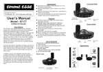
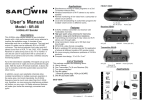
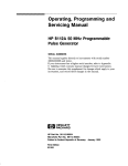
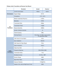
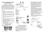
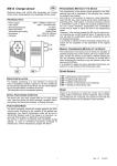
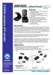
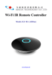
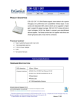
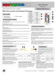
Application Introduction Transmitter – 699T 55..88G elle AV V SSe essss A GH Hzz W ennd de Wiirre err AWV699 IR extender jack AV IN jack User’s Manual DC Power jack LED indicator for power (green) Overview Setup & Operation CH. Selector 1 The AWV699 AV sender applies advanced 5.8GHz RF wireless technology to link all kinds of Audio and Video sources to TVs and Monitors with vivid video and crystal clear sound without wires or cables. The AWV699 features plug & play design to make the installation extremely easy. The use of 5.8GHz frequency band can avoid interferences in the crowded 2.4GHz frequency band and let you enjoy AV programs free of hassle. A. Transmitter 1.) Plug DC plug and AC plug of the DC power adaptor into DC power jack and AC power outlet respectively. 2.) Connect AV IN jack to AV out jack (RCA or SCART connector) of the AV source (e.g. DVD player) with the AV cable “Transmitter”. 3.) Face the IR window of transmitter toward IR sensor window of the AV source or plug IR extender cable into IR extender jack and attach the small IR LED emitter of the IR extender cable on the IR sensor window of the AV source. 4.) Turn on the power switch. CH. Selector 2 Power ON/OFF switch IR window Receiver – 699R Antenna adjustment for Azimuth and Zenith angle Features z z z z z z z Worldwide 5.8GHz ISM Band. 7 selectable RF channels. Transmission distance up to 300 feet. Compatible with both NTSC/PAL video formats. Comply with CE/FCC regulations. Build-in IR remote extender. Supply with SCART or RCA AV cables. Package contents AWV699T - Transmitter AWV699R - Receiver DC 9V/300mA power adapter . . . RCA(or SCART) to Ø3.5mm A/V cable . IR extender cable for transmitter . User Manual . AV Out jack DC Power jack B. Receiver LED indicator for power (green) CH. Selector 1 CH. Selector 2 . . . . . . . . . . . . . . . . . . . . . . . . . . . . . . .1 .1 .2 .2 .1 .1 pc pc pcs pcs pc pc Power ON/OFF switch IR window 1.) Plug DC plug and AC plug of the DC power adaptor into DC power jack and AC power outlet respectively. 2.) Connect AV OUT jack to AV IN jack (RCA or SCART connector) of the TV or monitor with the AV cable “Receiver”. 3.) Turn on the power switch. Trouble Shooting C. Channel selection 1.) There are two channel selection switches, CH Selector 1 and CH Selector 2 shown as below: Fig.1: Side view of AWV699 CH. Selector 1 CH. Selector 2 2.) Use CH. Selector 1 to select one of the two CH groups, CH (1,3,5,7) or CH (2,4,6). The corresponding channel numbers of CH. Selector 2 are shown as below: CH. Selector 2 CH. Selector 1 1 3 5 7 2 4 6 X 3.) Use CH. Selector 2 to select the desired channel. D. Operation 1.) Set the transmitter and receiver at the same channel. 2.) Adjust the azimuth and zenith angles of the receiver antenna so that it faces to the transmitter. Try to avoid transmission paths with any big meter object standing in the way. 3.) Arrange the transmitter so that its IR window faces to the IR sensor of your AV source device or plug the IR extender cable into the IR extender jack and attach its LED emitter on the window of the IR sensor of your AV source device. 4.) Point the Remote Controller of your AV source device toward the IR window of the receiver and use it to start playing your favorite video program. 1. Poor quality ¦ Multi-path interferences can degrade reception quality. Move the receiver and/or the transmitter slowly around an area within 8~10 inches in diameter or up and down vertically within 8~10 inches can usually improve the quality. ¦ If big metal obstructions in the transmission path can’t be avoid then readjust the azimuth and zenith angles of the receiver antenna to find the best reception orientation and try to shorten the distance between AWV699T and AWV699R as much as possible. ¦ Try to use a different channel out of the total 7 channels to avoid co-channel or adjacent channel interferences. 2. No pictures and sounds ¦ Check if the power switches of both AWV699T and AWV699R have been turned on. ¦ Check if AWV699T and AWV699R are set on the same channel? ¦ Check if the transmission distance is too far or any obstruction is in between AWV699T and AWV699R. The range is up to 100 meters line-of-sight, but walls, ceilings and metal objects can reduce it. ¦ Check if the transmitter’s AV cable is misused for the receiver and vice versa. General Specification Frequency Range 5725 ~ 5875 MHz Channel selection PLL Synthesizer 7CH Video/Audio Mod/Demod. Type. Negative Supply Voltage DC +9V/300mA Operating Frequency IR Extender Mod. /Demod. Type. 433MHz Antenna Type. Output Power 12dBm ± 2dB ( CE ) 0dBm ± 1dB ( FCC ) Antenna Type. Dipole Antenna IR Extender receiver Receiving Sensitivity -90dBm,min IR Carrier Frequency 38KHz, typ. IR LED Operation Range 4~5 Meters ± 45∘Horizontal IR Extender Half Angle External IR LED Port Ø2.5mm Mono Phone Jack Receiver Specification Input Sensitivity -85dBm, Typ. Video Output 1VP-P, ±0.2Vp-p Audio Output (50Hz~15KHz Sine Wave) Audio S/N Ratio (50Hz ~ 15KHz) Antenna Type. 2VP-P, typ. (+/-0.2Vp-p). 50dB, typ. (+/-3dB) Patch Antenna IR Extender Transmitter RF Output Power IR Receiver module carrier freq. 6dBm ±2dB ( CE ) 0dBm ±2dB ( FCC ) 38KHz, typ. IR Sensor Operation Range 7.5 Meters, min IR Sensor Half Angle ± 45∘Horizontal FM-FM Video Polarity Built-In IR Remote Extender Transmitter Specification Yes 433.92MHz ASK Omni-directional Dipole CE 0560 DOZ0000-0457