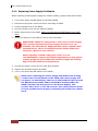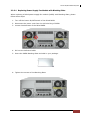
1
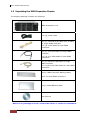
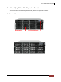
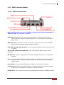
SAS to SAS/SATA
JBOD Subsystem
User Manual
Revision 1.0
SAS to SAS/SATA JBOD Subsystem
Table of Contents
Chapter 1 Introduction ......................................................................................... 3 1.1
Features .............................................................................................................................................................. 4 1.2
Technical Specifications ............................................................................................................................... 5 1.3
Unpacking the JBOD Expansion Chassis .............................................................................................. 6 1.4
Identifying Parts of the Expansion Chassis ......................................................................................... 7 1.4.1
Front View ................................................................................................................................................ 7 1.4.2
Rear View .................................................................................................................................................. 8 1.4.3
JBOD Controller Module .................................................................................................................... 9 1.4.3.1
1.5
JBOD Controller Panel ................................................................................................................ 9 Power Supply / Fan Module (PSFM) ................................................................................................... 10 1.5.1
PSFM Panel ........................................................................................................................................... 10 1.5.2
Power Supply Module LED............................................................................................................. 11 1.6
LCD Display Panel ....................................................................................................................................... 12 1.6.1
LCD Panel LED ..................................................................................................................................... 12 1.6.2
LCD Panel Function Buttons .......................................................................................................... 13 1.6.3
Menu Diagram .................................................................................................................................... 14 1.7
Drive Carrier Module ................................................................................................................................. 15 1.7.1
Disk Drive Status Indicators ........................................................................................................... 15 1.7.2
Drive Carrier Lock Indicator ........................................................................................................... 16 Chapter 2 Installation of JBOD Subsystem ................................................. 17 2.1
Powering On ................................................................................................................................................. 17 2.2
Disk Drive Installation................................................................................................................................ 18 2.2.1
Installing Disk Drive in a Disk Tray ............................................................................................. 18 2.2.2
Installing a SATA Disk Drive (Dual Controller Mode) in a Disk Tray ............................ 21 2.3
Connecting the JBOD Subsystem......................................................................................................... 25 2.3.1
Connecting to SAS HBA .................................................................................................................. 25 2.3.2
Connecting to RAID Subsystem ................................................................................................... 25 Chapter 3 Maintenance ..................................................................................... 26 3.1
Upgrading the JBOD Controller’s Firmware..................................................................................... 26 3.2
Replacing Subsystem Components ..................................................................................................... 30 3.2.1
Replacing JBOD Controller Module............................................................................................ 30 3.2.1.1
3.2.2
Replacing Power Supply Fan Module........................................................................................ 32 3.2.2.1
2
Replacing JBOD Controller Module with Blanking Plate .......................................... 31 Replacing Power Supply Fan Module with Blanking Plate ...................................... 33 User Manual
SAS to SAS/SATA JBOD Subsystem
Chapter 1 Introduction
The Expansion Chassis
The JBOD subsystem is a 19-inch 4U rackmount JBOD unit. It features the latest
SASII (6Gb/s) interface and designed to fit in with the environments which needed
highly reliable and relentless data growth. The JBOD subsystem is also a versatile
SAS2/SATA3 disk expansion system, ideal for high capacity and scalability storage in
IT demands. Based on the 6G SAS technology, the JBOD subsystem supports the
choice of SAS2 and SATA3 drive configurations to deliver the best cost-performance
index with higher bandwidth.
User Manual
3
SAS to SAS/SATA JBOD Subsystem
1.1 Features
Highest Density Available
- 4U chassis with 24 bays carriers
- Support the 2.5” / 3.5" enterprise class SAS2 / SATA3 disk drives
High Availability
- Single or dual SAS JBOD controller module
- Each SAS JBOD controller module consist of three 4x mini SAS ports
Power Supply
- Power supply and cooling system contained in 1 module for efficient cooling
- Two 500W redundant hot swappable power supplies
Enclosure
- Incorporates a cableless design for maximum signal integrity
SES
- Utilizes industry-standard SCSI enclosure services to monitor enclosure and disk
environmental conditions
Enclosure monitoring
- S.E.S. support for standard enclosure management
- System LED indications
- Fan speed monitoring
- Power supply monitoring
- System voltage monitoring
- System temperature monitoring
- System alarm
4
User Manual
SAS to SAS/SATA JBOD Subsystem
1.2 Technical Specifications
RAID Controller
JBOD
JBOD Controller
Single / Redundant
Host Interface
One / Two 4x mini SAS (6Gb/s)
Disk Interface
6Gb/s SAS, 6Gb/s SATA
SAS expansion
Two / Four 4x mini SAS (6Gb/s)
Enclosure
Platform
Rackmount
Form Factor
4U
# of Hot Swap Trays
24
Disk Status Indicator
Access / Fail LED
Backplane
SAS / SATA BP
# of PS/Fan Modules
500W x 2 w/PFC
# of Fans
4
Power requirements
AC 90V ~ 264V Full Range, 10A ~ 5A, 47Hz ~ 63Hz
Environmental
Relative Humidity
10% ~ 85% Non-condensing
Operating
Temperature
10°C ~ 40°C (50°F ~ 104°F)
Physical Dimension
607(L) x 482 (W) x 176(H) mm
Weight (Without Disk)
27.5Kgs
Specification is subject to change without notice.
All company and product names are trademarks of their respective owners.
User Manual
5
SAS to SAS/SATA JBOD Subsystem
1.3 Unpacking the JBOD Expansion Chassis
The shipping package contains the following:
JBOD Subsystem Unit
Two (2) power cords
One (1) external serial cable RJ11-to-DB9
for single JBOD controller
Two (2) serial cables for dual JBOD
controllers
One (1) mini SAS cable for single JBOD
controller
Two (2) mini SAS cables for dual JBOD
controllers
One (1) Ethernet LAN cable for single
JBOD controller
Two (2) Ethernet LAN cables for dual JBOD
controllers
One(1) JBOD Controller Blanking Plate
Note: For dual JBOD controllers
One(1) PSFM Blanking Plate
User Manual
NOTE: If any damage is found, contact the dealer or vendor for assistance.
6
User Manual
SAS to SAS/SATA JBOD Subsystem
1.4 Identifying Parts of the Expansion Chassis
The illustrations below identify the various parts of the expansion chassis.
1.4.1 Front View
Drive Carriers
LCD Display Panel
User Manual
7
SAS to SAS/SATA JBOD Subsystem
1.4.2 Rear View
Single Controller
Dual Controller
8
User Manual
SAS to SAS/SATA JBOD Subsystem
1.4.3 JBOD Controller Module
1.4.3.1 JBOD Controller Panel
NOTE: SAS IN/OUT Port can be flexibly configured as either SAS IN PORT or
SAS OUT PORT by customer's request
SAS IN Port: SAS cable must be connected to this port and to the SAS HBA, or
other Expansion Chassis’s SAS Expansion Port, if this chassis is connected in
daisy-chain.
SAS OUT Port: SAS cable must be connected to these ports and to other SAS IN
Port of other expansion chassis for daisy-chaining.
Link LED (SAS IN and SAS OUT): Green indicates SAS IN/OUT Port has connected
or linked.
Access LED (SAS IN and SAS OUT): Blue indicates SAS IN/OUT Port is being
accessed.
RS-232 Port: Used for upgrading the Firmware of JBOD controller in the Expansion
Chassis.
Mute: Use this button to silence the alarm beeper. If another failure event happens,
the alarm beeper will sound again and this button can be pressed again to
silence alarm.
System LED: Green indicates Expansion Chassis is Powered On and Ready.
Fault LED: Red (LED is on) indicates there is problem within the Expansion Chassis.
If LED is off, the Expansion Chassis is in normal condition.
R-Link Port: Use to connect to Telnet for upgrading the Firmware of JBOD controller
User Manual
9
SAS to SAS/SATA JBOD Subsystem
1.5 Power Supply / Fan Module (PSFM)
The JBOD subsystem contains two 500W Power Supply / Fan Modules. All
PSFMs are inserted into the rear of the chassis.
1.5.1 PSFM Panel
The Power Supply/Fan Module panel has: Power On/Off Switch, the AC Inlet
Plug, and a Power On/Fail Indicator showing the Power Status LED, indicating
ready or fail.
Each fan within a PSFM is powered independently of the power supply within
the same PSFM. So if the power supply of a PSFM fails, the fan associated with
that PSFM will continue to operate and cool the enclosure.
10
User Manual
SAS to SAS/SATA JBOD Subsystem
1.5.2 Power Supply Module LED
When the power cord connected from main power source is inserted to the AC
Power Inlet, the power status LED becomes RED. When the switch of the PSFM
is turned on, the LED will turn GREEN. When the Power On/Fail LED is GREEN,
the PSFM is functioning normally.
User Manual
11
SAS to SAS/SATA JBOD Subsystem
1.6 LCD Display Panel
1.6.1 LCD Panel LED
Parts
Function
Power LED
Green indicates power is ON.
Power Fail LED
Fan Fail LED
If one of the redundant power
supply unit fails, this LED will turn
to RED and alarm will sound.
Turn RED when fan 1 or 2 fails, or
speed is lower than 3000 RPM for
Master Fan and 2500 RPM for
Slave Fan.
Over Temperature LED
If system temperature is over
70oC or disk temperatures exceed
55oC, the Over Temperature LED
will turn RED and alarm will
sound.
Voltage Warning LED
An alarm will sound if detected
voltage in the controller is
abnormal and LED will turn RED.
12
User Manual
SAS to SAS/SATA JBOD Subsystem
1.6.2 LCD Panel Function Buttons
Parts
Function
Up and Down
Arrow buttons
Use the Up or Down arrow keys to
go through the information on the
LCD screen. This is also used to
move between each menu.
Select button
This is used to enter the option
you have selected.
Press this button to return to the
previous menu.
Exit button
EXIT
NOTE: This button can also be used
to silence the alarm beeper when
in main menu. If you are in
submenu and a failure event
happens, press the EXIT button
few times as necessary to go back
to main menu, and press again to
silence the alarm.
User Manual
13
SAS to SAS/SATA JBOD Subsystem
1.6.3 Menu Diagram
Model-Name
xxx.xxx.xxx.xxx
ID: xxxxxxxxxx
F/W V x.x.xx
Temperature
Enclosure 30’C
Chip
35’C
HDD01
33’C
:
HDD24
Power Status
Good
30’C
Power01 : Good
Power02 : Good
FAN Status
Good
Fan01:
Fan03:
Fan02:
Fan04:
Voltage Status
Good
1V_
1.03V
5V_
4.94V
3.3V_
3.24V
B12V_ 12.48V
Alarm Status
Enabled
Disable / Enable Alarm
System Reset
Enter Password
14
User Manual
3970
3970
3970
3970
rpm
rpm
rpm
rpm
SAS to SAS/SATA JBOD Subsystem
1.7 Drive Carrier Module
The Drive Carrier Module houses a 3.5 inch hard disk drive. It is designed for
maximum airflow and incorporates a carrier locking mechanism to prevent
unauthorized access to the HDD.
1.7.1 Disk Drive Status Indicators
Every Drive Carrier has 2 status indicator lights. One indicator light is used for
Power On/Error. When this light is GREEN the power is on and everything is
functioning normally. When the Power On/Error light is RED, then an error has
happened that requires the user’s attention.
The other status indicator light is the hard disk drive access light. When the
hard disk drive is being accessed, this light will flash BLUE.
In addition, both indicator lights are viewable within a 170° arc.
Disk Activity
Indicator
Disk Status
Indicator
User Manual
15
SAS to SAS/SATA JBOD Subsystem
1.7.2 Drive Carrier Lock Indicator
Every Drive Carrier is lockable and is fitted with a lock indicator to indicate
whether or not the carrier is locked into the chassis or not. Each carrier is also
fitted with an ergonomic handle for easy carrier removal.
Drive Carrier
is unlocked
When the Lock Groove is vertical, then the Drive Carrier is unlocked.
Drive Carrier
is locked
When the Lock Groove is horizontal, this indicates that the Drive Carrier is
locked.
Lock and unlock the Drive Carriers by using a flat-head screw driver.
16
User Manual
SAS to SAS/SATA JBOD Subsystem
Chapter 2 Installation of JBOD Subsystem
2.1 Powering On
1. Plug in the power cords into the AC Power Input Socket located at the rear of
the subsystem.
NOTE: The subsystem is equipped with redundant, full range
power supplies with PFC (power factor correction). The system
will automatically select voltage.
2. Turn on each Power On/Off Switch to power on the subsystem.
3. The Power LED on the front Panel will turn green.
User Manual
17
SAS to SAS/SATA JBOD Subsystem
2.2 Disk Drive Installation
This section describes the physical locations of the hard drives supported by the
subsystem and give instructions on installing a hard drive. The subsystem
supports hot-swapping allowing you to install or replace a hard drive while the
subsystem is running.
NOTE: In this model, it is recommended to use 6Gb hard drive
disks.
2.2.1 Installing Disk Drive in a Disk Tray
1. Unlock the Disk Trays using a flat-head screw driver by rotating the Lock
Groove.
2. Press the Tray Open button and the Disk Tray handle will flip open.
Tray
Open
Button
3. Pull out an empty disk tray.
18
User Manual
SAS to SAS/SATA JBOD Subsystem
4. Place the hard drive in the disk tray. Turn the disk tray upside down. Align the
four screw holes of the SAS disk drive in the four Hole A of the disk tray. To
secure the disk drive into the disk tray, tighten four screws on these holes of
the disk tray. Note in the picture below where the screws should be placed in
the disk tray holes.
Tray Hole A
NOTE: All the disk tray holes are labelled accordingly.
User Manual
19
SAS to SAS/SATA JBOD Subsystem
5. Slide the tray into a slot.
6. Press the lever in until you hear the latch click into place. The HDD Fault LED
will turn green when the subsystem is powered on and HDD is good.
7. If necessary, lock the Disk Tray by turning the Lock Groove.
20
User Manual
SAS to SAS/SATA JBOD Subsystem
2.2.2 Installing a SATA Disk Drive (Dual Controller Mode) in a Disk
Tray
1. Remove an empty disk tray from the subsystem.
2. Prepare the dongle board, the Fixed Bracket, and screws.
Fixed Bracket
Dongle Board
Screws
3. Attach the dongle board in the Fixed Bracket with a screw.
User Manual
21
SAS to SAS/SATA JBOD Subsystem
4. Place the Fixed Bracket with the dongle board in the disk tray as shown.
22
User Manual
SAS to SAS/SATA JBOD Subsystem
5. Turn the tray upside down. Align the holes of the Fixed Bracket in the two
Hole d of the disk tray. Tighten two screws to secure the Fixed Bracket into
the disk tray.
Tray Hole d
NOTE: All the disk tray holes are labelled accordingly.
6. Place the SATA disk drive into the disk tray. Slide the disk drive towards the
dongle board.
User Manual
23
SAS to SAS/SATA JBOD Subsystem
7. Turn the disk tray upside down. Align the four screw holes of the SATA disk
drive in the four Hole B of the disk tray. To secure the disk drive into the disk
tray, tighten four screws on these holes of the disk tray. Note in the picture
below where the screws should be placed in the disk tray holes.
Tray Hole B
NOTE: All the disk tray holes are labelled accordingly.
8. Insert the disk tray into the subsystem.
24
User Manual
SAS to SAS/SATA JBOD Subsystem
2.3 Connecting the JBOD Subsystem
2.3.1 Connecting to SAS HBA
The JBOD Subsystem supports SAS interface which provides fast 600MB data transfer
rate using SAS phy. Attach one end of the SAS cable to the SAS IN Port and the
other end to the host bus adapter’s (HBA) external SAS connector or to the SAS
Switch. (The host b u s adapter is installed in your Host computer system.)
2.3.2 Connecting to RAID Subsystem
Attach one end of the SAS cable to the SAS IN Port of the JBOD controller module
and the other end to the SAS Expansion Port on the RAID controller of RAID
subsystem. If configured in redundant mode, connect the other SAS cable to the
SAS IN Port of the other JBOD controller, and the other end to the SAS Expansion
Port on the other RAID controller of RAID subsystem.
User Manual
25
SAS to SAS/SATA JBOD Subsystem
Chapter 3 Maintenance
3.1 Upgrading the JBOD Controller’s Firmware
IMPORTANT: Before upgrade the JBOD firmware, please shut
down server first or make sure no array setting on the JBOD
disks. The new Firmware will effective after JBOD power cycle.
NOTE: Upgrading the firmware must be done from Master JBOD
Controller (JBOD Controller 1) if the JBOD Subsystem has
redundant JBOD Controllers.
Steps:
1. Please use the RS232 cable (Phone jack to DB9) to JBOD Controller #1 and to
connect JBOD RS232 Port and PC COM1 Port (or change to other COM Port as
necessary).
2. Open Windows HyperTerminal Program. Connect using COM1 (COM Port used in
Step1), Baud Rate: 115200, n, 8, 1, Flow Control: None.
3. Please type “system upgrade”, than press “Enter” in command line.
26
User Manual
SAS to SAS/SATA JBOD Subsystem
4. Select Transfer & Send File.
You must finish within 25 seconds
5. Select your firmware file path, and select Xmodem in the communication protocol,
and click transfer button.
User Manual
27
SAS to SAS/SATA JBOD Subsystem
6. Wait for the transfer of file to complete.
28
User Manual
SAS to SAS/SATA JBOD Subsystem
7. When the transfer and firmware update is complete, please power cycle the JBOD.
8. In command line, type “system info”, you can see the Expander firmware version.
User Manual
29
SAS to SAS/SATA JBOD Subsystem
3.2 Replacing Subsystem Components
3.2.1 Replacing JBOD Controller Module
When replacing a failed JBOD Controller Module, please follow these steps:
1. Make sure the subsystem is in power off state. Loosen the thumbscrews on
the sides of the Controller Module case.
2. Use the Controller handle to pull out the defective Controller.
3. Insert and slide the new Controller in. Note that it may be necessary to
remove the old/defective Controller Module from the case and install the new
one.
4. Tighten the thumbscrews on the sides of the Controller Module case.
30
User Manual
SAS to SAS/SATA JBOD Subsystem
3.2.1.1 Replacing JBOD Controller Module with Blanking Plate
When replacing a failed Controller Module with Blanking Plate, please follow these
steps:
1. Loosen thumbscrews of the failed Controller Module.
2. Use the Controller Module handle to remove the failed Controller Module from
the subsystem.
3. Insert the Controller Blanking Plate included in your package.
4. Tighten the screws of the Blanking Plate.
When replacing a failed component online, it is not recommended to
remove the failed component for a long period of time; proper air
flow within the enclosure might fail causing high controller/disk
drive temperature.
User Manual
31
SAS to SAS/SATA JBOD Subsystem
3.2.2 Replacing Power Supply Fan Module
When replacing a failed power supply fan module (PSFM), please follow these steps:
1. Turn off the Power On/Off Switch of the failed PSFM.
2. Disconnect the power cord from the AC Inlet Plug of PSFM.
3. Loosen thumbscrews of the PSFM.
4. Use the handle to pull out the defective PSFM.
5. Before inserting the new PSFM, make sure the Power On/Off Switch is on "Off"
state.
6. Insert and slide the new PSFM in until it clicks into place.
IMPORTANT: When the subsystem is online and a Power Supply
fails, and the replacement Power Supply module is not yet
available, the failed Power Supply Module can be replaced with
the Plate Cover. This is to maintain proper airflow within the
enclosure. (Refer to next section)
When replacing a failed component online, it is not
recommended to remove the failed component for a long period
of time; proper air flow within the enclosure might fail causing
high controller/disk drive temperature.
7. Connect the power cord to the AC Inlet Plug of PSFM.
8. Tighten the thumbscrews of the PSFM.
9. Turn on the Power On/Off Switch of the PSFM.
NOTE: After replacing the Power Supply Fan Module and turning
on the Power On/Off Switch of the PSFM, the Power Supply will
not power on immediately. The Fans in the PSFM will spin-up until
the RPM becomes stable. When Fan RPM is already stable, the
RAID controller will then power on the Power Supply. This
process takes more or less 30 seconds. This safety measure helps
prevent possible Power Supply overheating when the Fans cannot
work.
32
User Manual
SAS to SAS/SATA JBOD Subsystem
3.2.2.1 Replacing Power Supply Fan Module with Blanking Plate
When replacing a failed power supply fan module (PSFM) with Blanking Plate, please
follow these steps:
1. Turn off the Power On/Off Switch of the failed PSFM.
2. Disconnect the power cord from the AC Inlet Plug of PSFM.
3. Loosen thumbscrews of the failed PSFM.
4. Pull out the defective PSFM
5. Insert the PSFM Blanking Plate included in your package.
6. Tighten the screws of the Blanking Plate.
User Manual
33