1
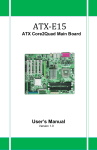
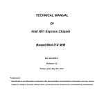
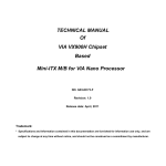
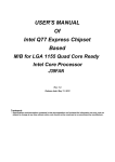
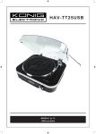
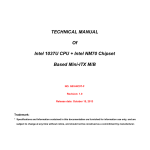
USER'S MANUAL
Of
AMD A55 Chipset
Based
M/B for Socket FM1 AMD Processor
NO. G03-TA55M-L-F
Rev:1.0
Released in: April, 2012
Trademark:
* Specifications and information contained in this documentation are furnished for information use only, and are
subject to change at any time without notice, and should not be construed as a commitment by manufacturer.
Environmental Safety Instruction
z
Avoid the dusty, humidity and temperature extremes. Do not place the product in any
area where it may become wet.
z
0 to 40 centigrade is the suitable temperature. (Actual figure depends on the request of
the main chipset)
z
Generally speaking, dramatic changes in temperature may lead to contact malfunction
and crackles due to constant thermal expansion and contraction from the welding
spots’ that connect components and PCB. Computer should go through an adaptive
phase before it boots when it is moved from a cold environment to a warmer one to
avoid condensation phenomenon. These water drops attached on PCB or the surface
of the components can bring about phenomena as minor as computer instability
resulted from corrosion and oxidation from components and PCB or as major as short
circuit that can burn the components. Suggest starting the computer until the
temperature goes up.
z
The increasing temperature of the capacitor may decrease the life of computer. Using
the close case may decrease the life of other device because the higher temperature in
the inner of the case.
z
Attention to the heat sink when you over-clocking. The higher temperature may
decrease the life of the device and burned the capacitor.
Environmental Protection Announcement
Do not dispose this electronic device into the trash while discarding. To minimize pollution
and ensure environment protection of mother earth, please recycle.
ii
TABLE OF CONTENT
CHAPTER 1
1-1
1-2
1-3
INTRODUCTION OF MOTHERBOARDS
MOTHERBOARD SPECIFICATION ........................................................................... 1
SPECIAL FREATURES ............................................................................................ 2
LAYOUT DIAGRAM .................................................................................................. 4
CHAPTER 2
HARDWARE INSTALLATION
2-1 HARDWARE INSTALLATION STEPS ....................................................................... 5
2-2 JUMPER SETTING...................................................................................................... 5
2-3 CPU INSTALLATION.................................................................................................. 6
2-3-1 ABOUT AMD FM1 CPU SOCKET ................................................................ 6
2-3-2 CPU INSTALLATION GUIDE ....................................................................... 6
2-4 MEMORY INSTALLATION ......................................................................................... 7
2-5 EXPANSION CARD INSTALLATION......................................................................... 8
2-5-1 EXPANSION SLOTS..................................................................................... 8
2-5-2 PROCEDURE FOR EXPANSION CARD INSTALLATION .......................... 8
CHAPTER 3
3-1
3-2
3-3
CHAPTER 4
4-1
4-2
CONNCTORS AND HEADERS
I/O BACK PANEL CONNECTORS............................................................................. 9
MOTHERBOARD INTERNAL CONNECOTRS .......................................................... 10
HEADERS ................................................................................................................... 12
USEFUL HELP
HOW TO UPDATE BIOS ............................................................................................ 14
TROUBLE SHOOTING ............................................................................................... 14
APPENDIX...................................................................................................................15
ii
Chapter 1
Introduction of Motherboards
1-1 Motherboard Specification
Spec
Description
Chipset
z
z
z
Micro-ATX Form Factor
Size:23 x18 cm
AMD™ A55 FCH (Hudson D2) Chipset
CPU Socket
z
z
AMD™ Socket FM1:
Support AMD™ A- & E2- “Lynx” Series APU
* For more detailed CPU support information please visit our website
240-pin DDRIII Module slot x 2
Support 2pcs of DDRIII 1066/1333/1600/1866 memory modules
expandable to 16GB
Dual channel supported
1pcs * PCI-Express 2.0 x16 by 16 lane slot
1pcs * PCI-Express 2.0 x1 slot
1pcs * PCI slot
4* SATAII 3Gb/s connectors
Integrated with PCI-E megabit LAN chip providing 10/100Mbps data
transfer rate
Support Fast Ethernet LAN function
6-channel HD Audio Audio Codec integrated
Audio driver and utility included
Design
Memory Slot
Expansion Slot
Storage
z
z
z
z
z
z
z
z
LAN Chip
z
z
HD Audio Chip z
z
z
z
z
z
z
z
z
Multi I/O
z
z
z
z
z
z
z
z
Item Checklist z
z
BIOS
z
16MB Flash ROM BIOS
PS/2 keyboard connector x1
PS/2 mouse connector x1
VGA connector x1
DVI connector x1
USB 2.0 port x 4
USB 2.0 header x 2
RJ-45 LAN connector x1
Audio connector x1
Front panel audio header x1
HDMI-SPDIF header x1
Speaker header x1
PWR LED header x1
Front panel header x1
Motherboard
DVD for motherboard utilities
User’s Manual
Hard Disk Cable
Back Shied
1
1-2 Special Features
APU
Accelerated Processing Unit (APU) is the unique combination of
CPU and GPU computing technology. It is designed to vastly
improve today’s internet, video processing, playback and gaming
experiences.
AMD Radeon™ Dual Graphics
The AMD™ Dual Graphics technology combines APU and GPU
computing power to optimize user’s visual experience.
Microsoft® DirectX® 11
DirectX ® 11 is the latest in high speed, high fidelity gaming and
computing. It can enable not just more visually stunning games, but
significant performance improvements in some of your favorite
websites and everyday applications.
AMD Steady Video™
New Video Post Processing Capability: automatic jitter reduction on
home/online video.
AMD Steady Video™
AMD
Core™
Turbo AMD Turbo Core™
Dynamic adjustment of CPU and GPU performance, Automatically
detects the load, without any driver support.
2
0 ~ 400MHz
Normal load, APU to keep
low frequency energy
3D games, film and television
production and other heavy loads, APU
automatic over clocking
CPU Vcore OC-CON Solid Capacitors
This series of boards adopt OC-CON solid capacitors for CPU
Vcore power. OC-CON solid capacitors make it possible for
motherboard to work from 55 degrees Centigrade below zero to 125
degrees centigrade. OC-CON capacitors possess superior physical
characteristics to prolong product life ten times than corresponding
motherboard without capacitors every time working temperature
increases 20 degrees. Life of product of motherboard with solid
capacitors declines only 10% of those without solid capacitors as
well under same conditions.
Other
Features CPU Smart Fan—Noise Management System
include:
It’s never been a good idea to gain the performance of your system
by sacrificing its acoustics. CPU Smart Fan Noise Management
System is the answer to control the noise level needed for
now-a-day’s high performance computing system. The system will
automatically increase the fan speed when CPU operating loading is
high, after the CPU is in normal operating condition, the system will
low down the fan speed for the silent operating environment. The
system can provide the much longer life cycle for both CPU and the
system fans for game use and business requirements.
3
1-3 Layout Diagram
PS/2 Mouse
Port
RJ-45 LAN Port
VGA Port
Line-In
DVI Port
PS/2 Keyboard
Port
Line-Out
MIC-In
USB 2.0 Ports
ATX 12V Power Connector
CPUFAN Header
PS/2 Mouse Port over
PS/2 Keyboard Port
JP2
VGA Port
AMD FM1
CPU Socket
DDRIII Slot x 2
DVI Port
USB 2.0 Ports
RJ-45 Port over
USB 2.0 Ports
Audio Connector
LAN Chip
ATX Power Conn.
PCI Express x 16 by 16-lane Slot
PCI Express x1 Slot
AMD A55 Chipset
6-CH
HD Audio Chip
PCI Slot
SATAII Ports
(SATA3/4)
JBAT1
Power LED Header
Front Panel
Audio Header
HDMI-SPDIF Header
SYSFAN1 Header
SATAII Ports
(SATA1/2/3/4)
Speaker Header
USB 2.0 Headers
Front Panel Header
4
Chapter 2
Hardware Installation
WARNING!
2-1
Turn off your power when adding or removing expansion cards or
other system components. Failure to do so may cause severe
damage to both your motherboard and expansion cards.
Hardware Installation Steps
Before using your computer, you had better complete the following steps:
1. Check motherboard jumper setting
2. Install CPU and Fan
3. Install System Memory (DIMM)
4. Install Expansion cards
5. Connect hard disk and front panel /back panel cable
6. Connect ATX Power cable
7. Power-On and Load Standard Default
8. Reboot
9. Install Operating System
10. Install Driver and Utility
2-2 Jumper Setting
(1)
JBAT (3-pin): CMOS RAM Clear
A battery must be used to retain the motherboard configuration in CMOS RAM
short 1-2 pins of JBAT to store the CMOS data.
To clear the CMOS, follow the procedure below:
1. Turn off the system and unplug the AC power.
2. Remove ATX power cable from ATX power connector.
3. Locate JBAT and short pins 2-3 for a few seconds.
4. Return JBAT to its normal setting by shorting pins 1-2.
5. Connect ATX power cable back to ATX power connector.
Note: When should clear CMOS
1. Troubleshooting
2. Forget password
3. After over clocking system boot fail
JBAT
JBAT
1-2 Closed:
Normal
2-3 Closed:
CMOS RAM Clear Setting
5
Clear CMOS
(2) JP2 (3-pin): Keyboard/USB function Enabled/Disabled
JP2
JP2
1-2 Closed:KB/USB Power ON Disable ;
2-3 Closed: KB/USB Power ON Enabled
Keyboard/ & USB Power On Setting
2-3 CPU Installation
2-3-1 About AMD FM1 CPU Socket
This motherboard provides an AMD FM1 socket.
The CPU that comes with the motherboard should have a cooling FAN attached to
prevent overheating. If this is not the case, then purchase a correct cooling FAN
before you turn on your system.
WARNING!
Be sure that there is sufficient air circulation across the processor’s
heatsink and CPU cooling FAN is working correctly, otherwise it may
cause the processor and motherboard overheat and damage, you
may install an auxiliary cooling FAN, if necessary.
To install a CPU, first turn off your system and remove its cover. Then find Pin-1
(small triangle indicator) of the CPU and make sure to install it matched with Pin-1
(small triangle indicator) of the CPU socket. See to it that system is turned off and the
installation direction is correct. If the installation direction is wrong, CPU can not be
installed into the socket. In this case do not try to force it into the socket, but to change
to the correct direction.
2-3-2 CPU Installation Guide
1. Locate APU socket.
2. Find APU socket
Pin-1(with small triangle
indicator).
6
3. Find APU Pin-1
(with small triangle
indicator).
4. Open the socket by
pulling the level
sideways away from the
socket and then upwards
to a 90-degree angle.
2-4
6. Put the level to the
original place of the
socket. Make sure that
the notched corner
should point towards
the end of the level.
5. Insert compatible APU
into APU socket and see
to it that APU Pin-1
should be matched into
APU socket Pin-1 during
installation.
Memory Installation
This motherboard provides two 240-pin DDR III SDRAM DUAL INLINE MEMORY
MODULES (DIMM) socket for DDRIII memory expansion to maximum memory
volume of 16GB.
Valid Memory Configuration
Bank
240-Pin DIMM
PCS
Maximum Capacity
DIMM1
DIMM2
Total
DDR III 800/1066/1333/1600/1866
DDR III 800/1066/1333/1600/1866
System Memory (Max.4GB)
X1
X1
2
8GB
8GB
16GB
Recommend DIMM Module Combination
1. One DIMM Memory Module ----Plug in DIMM 1.
2. Two DIMM Memory Modules---Plug in DIMM1 and DIMM2 for Dual channel
function.
Dual channel Limited!
1. Dual channel function only supports when 2 memory modules pluged in both
DIMMI1 & DIMM 2.
2. Memory modules plugged in DIMMI1 & DIMM 2 must be of the same type, same
size, and same frequency for dual channel function.
Install DDRIII modules to your motherboard is not difficult, you can refer to figure
below to see how to install DDRIII 800/1066/ 1333/1600/1866 SDRAM module.
7
DIMM1&DIMM2
Support Dual-Channel
NOTE! When you install DIMM module fully into the DIMM socket the eject tabs
should be locked into the DIMM module very firmly and fit into its indention on both
sides.
2-5 Expansion Card Installation
2-5-1 Expansion Slots
This series of boards offers one PCI-Express 2.0 x 16 by 16 lane graphics slot, one
PCI Express 2.0 x1 slot and one PCI slot to guarantee the rich connectivity for the I/O
of peripherals.
PCI-E 2.0 x1 Slot
PCI-E 2.0 x16 by 16 Lane slot
PCI Slot
2-5-2 Procedure for Expansion Card Installation
1.
2.
3.
4.
5.
6.
7.
Read the documentation for your expansion card and make any necessary
hardware or software setting for your expansion card such as jumpers.
Remove your computer’s cover and the bracket plate on the slot you intend to
use.
Align the card’s connectors and press firmly.
Secure the card on the slot with the screen you remove above.
Replace the computer system’s cover.
Set up the BIOS if necessary.
Install the necessary software driver for your expansion card.
8
Chapter 3
Connectors and Headers
3-1 I/O Back Panel Connectors
PS/2 Mouse
Port
RJ-45 LAN Port
VGA Port
Line-In
DVI Port
PS/2 Keyboard
Port
Line-Out
MIC-In
USB 2.0 Ports
(1) PS/2 Mouse & PS/2 Keyboard Connector: KB
The connectors are for PS/2 keyboard and PS/2 Mouse. The green one is PS/2
mouse port and the purple one is PS/2 keyboard port.
(2) D-Sub 15-pin Connector: VGA
VGA is the 15-pin D-Subminiature female connector; it is for the display devices,
such as the CRT monitor, LCD monitor and so on.
(3) Digital Visual Interface: DVI
This interface standard designed to maximize the visual quality of digital display
devices such as flat panel LCD computer displays and digital projectors.
(4) USB 2.0 Ports: from CN1/ UL1
The connectors are 4-pin USB 2.0 connectors to connect USB devices to the
system board.
(5) RJ-45 LAN Port connector: from UL1
The connector is standard RJ-45 connector for Network. It supports 10/100
Mbps data transfer rate.
(6) Audio Line-In, Line-Out, MIC Connector: CN3
These Connectors are 3 Phone-Jack for LINE-OUT, LINE-IN, and MIC audio
connections.
Line-in: (BLUE)
Line-out: (GREEN)
MIC: (PINK)
Audio input to sound chip
Audio output to speaker
Microphone Connector
9
3-2 Motherboard Internal Connectors
(1)
Power Connector (24-pin block): ATXPWR1
ATX Power Supply connector: This is a new defined 24-pin connector that
usually comes with ATX case. The ATX Power Supply allows using soft power
on momentary switch that connect from the front panel switch to 2-pins Power
On jumper pole on the motherboard. When the power switch on the back of the
ATX power supply turned on, the full power will not come into the system board
until the front panel switch is momentarily pressed. Press this switch again will
turn off the power to the system board.
** We recommend that you use an ATX 12V Specification 2.0-compliant power
supply unit (PSU) with a minimum of 350W power rating. This type has 24-pin
and 4-pin power plugs.
** If you intend to use a PSU with 20-pin and 4-pin power plugs, make sure that the
20-pin power plug can provide at least 15A on +12V and the power supply unit
has a minimum power rating of 350W. The system may become unstable or may
not boot up if the power is inadequate.
** Please refer to Figure 1 for 20-pin power plug connection. Power plug and
motherboard power connectors has adopted key design to avoid installation
mistake through connection can be made easily if in the proper direction. If the
installation direction is incorrect and you make the connection by force both the
board and the power supply can be burned. Please see to it that the direction is
correct during installation.
ROW1 ROW2
PIN
ROW1 ROW2
Pin 1
Pin 1
20-Pin
24-Pin
Figure 1: 20-pin power plug
ROW1
ROW2
1
3.3V
3.3V
2
3.3V
-12V
3
GND
GND
4
5V
Soft Power On
5
GND
GND
6
5V
GND
7
GND
GND
8
Power OK
-5V
9
+5V (for Soft Logic)
+5V
10
+12V
+5V
11
+12V
+5V
12
+3V
GND
Figure2: 24-pin power plug
10
(2) ATX 12V Power Connector (4-pin block): ATX12V
This is a new defined 4-pins connector to provide extra 12V for system stability.
Without this connector might cause system unstable because the power supply
can not provide sufficient current for system.
Pin1
Pin No.
1
Definition
GND
2
GND
3
+12V
4
+12V
(3) FAN Power Headers: SYSFAN1 (3-pin), CPUFAN (4-pin)
These connectors support cooling fans of 350mA (4.2 Watts) or less, depending
on the fan manufacturer, the wire and plug may be different. The red wire should
be positive, while the black should be ground. Connect the fan’s plug to the
board taking into consideration the polarity of connector.
CPUFAN
1
4
SYSFAN1
1
3
(4)SATA II Hard Disk Connector: SATA1, SATA 2, SATA3, SATA4
These are SATAII hard disk ports. Please connect SATA device to the
connector with SATA cable. One connector supports one SATA device.
Pin No.
1
Defnition
GND
2
TXP
3
TXN
4
GND
5
RXN
6
RXP
7
GND
11
3-3 Headers
(1) Line-Out/MIC Header for Front Panel (9-pin): AUDIO1
These headers connect to Front Panel Line-out, MIC connector with cable.
KEY
LINE2-JD
MIC2-JD
Audio-JD
Audio-GND
2
10
Pin 1
9
Lineout2-L
Sense-FB
Lineout2-R
MIC2-R
MIC2-L
(2) USB 2.0 Port Headers (9-pin): USB1/USB2
These USB 2.0 headers are used for connecting the additional USB 2.0 port
plugs. By attaching an option USB 2.0 cable, your can be provided with two
additional USB 2.0 plugs affixed to the back panel.
NC
GND
+DATA
VCC
-DATA
Pin 1
GND
+DATA
-DATA
VCC
(3) Speaker connector: SPEAK1
This 4-pin header connects to the case-mounted speaker. See the figure below.
(4) Power LED: PWR LED/PWRLED1
The Power LED is light on while the system power is on. Connect the Power
LED from the system case to this pin.
(5) Hard disk activity LED: HD LED
This header connects to the hard disk activity indicator light on the case.
(6) Reset switch: RESET
This 2-pin header connects to the case-mounted reset switch for rebooting your
computer without having to turn off your power switch. This is a preferred
method of rebooting in order to prolong the lift of the system’s power supply.
See the figure below.
(7) Power switch: PWR BTN
This 2-pin header connects to the case-mounted power switch to power
ON/OFF the system.
12
PWR LED
PWRBTN
GND
PWRBTN
JW FP1
PWRLED+
P WRLED-
PWRLED
Pin 1
SPEAK
RS TS W
NC
RESET
GND
HDDLED-
HDLED
GND
VCC5
SPKR
NC
HDDLED+
Pin 1
Pin 1
System Case Connections
(8) HDMI-SPDIF Out header: HDMI_SPDIF
The SPDIF output is capable of providing digital audio to external speakers or
compressed AC3 data to an external Dolby digital decoder. Use this feature only
when your stereo system has digital input function. Some of the VGA Card need
connect SPDIF-IN Connector,so its HDMI Port can make sounds .
HDMI_SPDIF_OUT
GND
Pin1
13
Chapter 4
Useful Help
4-1 How to Update BIOS
Solution1: Updating BIOS under DOS:
1. Prepare a bootable disk. (You may make one by click START click RUN type SYS
A:
click OK)
2. Download upgrade tools and the latest BIOS files of the motherboard from official
website and then make a copy of it to your bootable floppy disk after
decompressing these files
3. Insert the disk into A: ,start your computer and then type in
“A:\xxxxxx.BAT”(xxxxxxx being the file name of the latest BIOS )
4. Type Enter to update and flash the BIOS. The system will restart automatically
when BIOS is upgraded.
Solution2: Updating BIOS under Windows operating system:
1. Download Windows version BIOS from our website.
2. Unzip the downloaded file.
3. Double click EXE file to activate it and follow on-screen instructions for further
operations.
4-2 Trouble Shooting
Problem
No power to the system to the all
power light don’t illuminate, fan inside
power supply doesn’t turn on.
System inoperative. Keyboard lights
are on, power indicator lights are lit,
and hard drive is spinning.
System doesn’t boot from hard disk
drive, can be booted from optical drive.
System only boots from optical
drive .Hard disk can be read and
applications can be used but booting
from hard disk is impossible.
Screen
message
says
“Invalid
Configuration” or “CMOS Failure”
Solution
1. Make sure power cable is security
plugged in. 2. Replace cable. 3.
Contact technical support.
Using ever pressure on both ends of
the DIMM, press down firmly until the
module snaps into places.
1. Check cable running from disk to
disk controller board. .Make sure both
ends are securely plugged in, check
the drive type in the standard CMOS
setup. 2. Backing up the hard drive is
extremely important .All hard disks are
capable of breaking down at any time.
1. Back up date and applications files.
2. Reformat the hard drive. Reinstall
applications and date using backup
disks.
Review system‘s equipment. Make
sure correct information on is in setup.
14
Appendix
Subject 1: Regarding the Application of 3-Phase or 3+1 Phase
Power Supply Mold
As a result of the increasing power consumption demand from many
AMD CPUs in current market, we suggest not to use a CPU that
demands more than 65W power consumption at work for an AMD CPU
compliant board that comes with power supply design as 3 phase or
3+1 phase mold and MOSFET design as working in High SideX1 and
Low SideX1 mold so as to avoid MOSFET getting burned or other
phenomena like a halted system or system instability. So please take notice of the
CPU you are using and make sure that it is one that demand not more than 65 W to
ensure long-term working order.
Note:
1. The relation between CPU Power Consumption Amount and Power Phase:
depending on difference in voltage rating, one-phase of power can provide
25~30W to the motherboard.
2. 3- Phase Power Supply Mold: motherboard with 3 inductances for CPU power
supply, and each inductance carries with it 2 MOSFET (6 MOSFETs in total)
(Figure1);3+1–Phase Power Supply Mold: motherboard with 4 inductances for
CPU power supply, and each inductance carries with it 2 MOSFET (8 MOSFETs
in total) (Figure2)
Figure 1
Figure 2
Solution:
We recommend users choose motherboards with power design of 4-phase, 4+1
phase or more for CPUs that demand 89W or 95W power consumption.
We recommend users choose motherboards with power design of 5-phase, 5+1
phase or more for CPUs that demand 125W or 140W power consumption.
15
Subject 2: Suggestion on choosing electric fan
Both the amount of electric current to MOSFET and the heat produced
from the motherboard go up as AMD’s CPU power consumption
increases. In this case we recommend users select a CPU fan with air
outlet towards MOSFET so that CPU fan can carry away heat
produced by MOSFET, for better heat dissipation effects. At the same
time we suggest using well-ventilated cases to maintain temperature as 38℃
approximately inside. (38℃ is recommended by CPU manufactures).
Cool air flowing in
Hot air flowing out
MOSFET
Figure 1---- CPU Fan can not blow off the heat produced by MOSFET. We suggest
not to using fans of this kind.
Cool air flowing in
Hot air flowing out
MOSFET
Figure 2---- CPU Fan can blow off the heat produced by MOSFET. We suggest using
fans of this kind.
Subject 3: Thunder Protection Feature
Introduction:
Thunder is such formidable natural force that it can render massive damage to electronic
products of all kinds. In thunderstorm season computer systems without powerful thunder
protection designs are vulnerable to electric surge damage. High-priced building with
thunder protection measures may be a good choice, but usually costly and with corners
16
uncovered. The best solution for both cybercafés owner and common users would be
Thunder Series motherboards.
Thunder Protection Technology from Thunder Series Motherboard
Thunder series motherboards are integrated with double thunder-protection walls, one from
network port and the other from LAN chip. When it thunders, the first thunder-protection wall
will analyze and recognize thunder surge in network cable and transfer it to ground wire area.
The second thunder-protection wall will protect against any residual electric current or
runaway electrons to ensure safety of network card and other components of the
motherboard.
Laboratory test statistics on IEC61000-4-5 (1.2-50us) standardized thunder electric surge
tests have verified that Thunder series motherboard can endure up to 9KV electric surge
and protect the system from possible thunder damage.
IEC61000-4-5 (1.2-50us) Standardized Thunder Electric Surge Laboratory Test
Medium rise time: T1=1.2us±30%, T2=50us±30%
Test1: Current Partial Discharge tests on Thunder Series Motherboards with double
Thunder-protection Walls.
Test Result: Each MB can endure up to 9KV voltage of electric surge. Some motherboards
will restart (mostly depends on LAN chip), but no damage occurs to motherboards or
components of the board. System works normally after a restart.
Test2: Current Partial Discharge tests on Motherboards without Thunder-protection function
Test Result: LAN chips are damaged when testing voltage reached to 5KV. System fails to
operate normally (in most cases systems can not access to network) after a restart.
Conclusion: Thunder Series motherboard can guard motherboard from thunder surge
damage with effect and ensure system security from as high as 9KV volts of electric surge.
Bonus of Thunder-protection Motherboard
Thunder series motherboards adopt dual thunder protection walls to cover every corner in
network loops. Such a complete thunder protection provided to users, especially cybercafés
means less repair cost and more effective business time. Thunder series can guard system
stability with effect. With Thunder series motherboards, together with reasonable disposal of
electric wires, proper placing of electric devices, piped network cables and other necessary
thunder protection devices, your computer system will be intact in thunderstorm weather.
17