1
Storage Library System for
OpenVMS
Guide to Backup and Restore
Operations
Abstract
This document contains information for performing backup, archive, and restore operations
using Storage Library System for OpenVMS(SLS) software.
Revision/Update Information: This revised document supersedes the previous release of this document
Software Version:
Hewlett-Packard Company
Palo Alto, California
Storage Library System for OpenVMS
Version 2.9J
January 2005
© 2005 Hewlett-Packard Development Company, L.P
The information contained herein is subject to change without notice. The only warranties for HP products and services are set forth in the express warranty statements accompanying such products and services. Nothing herein
should be construed as constituting an additional warranty. HP shall not be liable for technical or editorial errors or
omissions contained herein.
Proprietary computer software. Valid license from HP required for possession, use or copying. Consistent with
FAR 12.211 and 12.212, Commercial Computer Software, Computer Software Documentation, and Technical Data
for Commercial Items are licensed to the U.S. Government under vendor's standard commercial license.
Printed in the U.S.A.
Contents
Preface . . . . . . . . . . . . . . . . . . . . . . . . . . . . . . . . . . . . . . . . . . . . . . . . . . . . . . . . . . . . . . . . . . . xxi
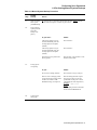
1 Introduction to Storage Library System for OpenVMS
1.1 SLS Storage Management Concepts . . . . . . . . . . . . . . . . . . . . . . . . . . . . . . . . . . . . . . . . . . . . . . . . . . . . .
1.1.1
Why You Save Data . . . . . . . . . . . . . . . . . . . . . . . . . . . . . . . . . . . . . . . . . . . . . . . . . . . . . . . . . . . . . .
1.1.1.1
Backup Copy of Data . . . . . . . . . . . . . . . . . . . . . . . . . . . . . . . . . . . . . . . . . . . . . . . . . . . . . . . . . .
1.1.1.2
Archive Copy of Data . . . . . . . . . . . . . . . . . . . . . . . . . . . . . . . . . . . . . . . . . . . . . . . . . . . . . . . . .
1.1.1.3
Defining Data Safety Policy . . . . . . . . . . . . . . . . . . . . . . . . . . . . . . . . . . . . . . . . . . . . . . . . . . . . .
1.1.1.4
Policy Implementation and Administration . . . . . . . . . . . . . . . . . . . . . . . . . . . . . . . . . . . . . . . . .
1.2 Storage Management Responsibilities . . . . . . . . . . . . . . . . . . . . . . . . . . . . . . . . . . . . . . . . . . . . . . . . . . . .
1.2.1
Storage Administrator's Responsibilities . . . . . . . . . . . . . . . . . . . . . . . . . . . . . . . . . . . . . . . . . . . . . . .
1.2.2
Operator's Responsibilities . . . . . . . . . . . . . . . . . . . . . . . . . . . . . . . . . . . . . . . . . . . . . . . . . . . . . . . . .
1.2.3
User's Responsibilities . . . . . . . . . . . . . . . . . . . . . . . . . . . . . . . . . . . . . . . . . . . . . . . . . . . . . . . . . . . . .
1-1
1-1
1-1
1-2
1-2
1-2
1-2
1-3
1-3
1-4
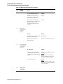
2 Using SLS Menu Interfaces
2.1 SLS Menus . . . . . . . . . . . . . . . . . . . . . . . . . . . . . . . . . . . . . . . . . . . . . . . . . . . . . . . . . . . . . . . . . . . . . . . . .
2.2 Administrator Menu . . . . . . . . . . . . . . . . . . . . . . . . . . . . . . . . . . . . . . . . . . . . . . . . . . . . . . . . . . . . . . . . . .
2.2.1
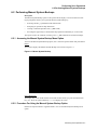
Accessing the Administrator Menu . . . . . . . . . . . . . . . . . . . . . . . . . . . . . . . . . . . . . . . . . . . . . . . . . . .
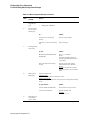
2.2.2
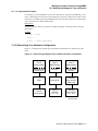
Administrator Menu Diagram . . . . . . . . . . . . . . . . . . . . . . . . . . . . . . . . . . . . . . . . . . . . . . . . . . . . . . .
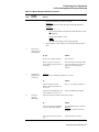
2.2.3
Administrator Menu Options . . . . . . . . . . . . . . . . . . . . . . . . . . . . . . . . . . . . . . . . . . . . . . . . . . . . . . . .
2.3 Operator Menu . . . . . . . . . . . . . . . . . . . . . . . . . . . . . . . . . . . . . . . . . . . . . . . . . . . . . . . . . . . . . . . . . . . . . .
2.3.1
Accessing the Operator Menu . . . . . . . . . . . . . . . . . . . . . . . . . . . . . . . . . . . . . . . . . . . . . . . . . . . . . . .
2.3.2
Operator Menu Diagram . . . . . . . . . . . . . . . . . . . . . . . . . . . . . . . . . . . . . . . . . . . . . . . . . . . . . . . . . . .
2.3.3
Operator Menu Options . . . . . . . . . . . . . . . . . . . . . . . . . . . . . . . . . . . . . . . . . . . . . . . . . . . . . . . . . . . .
2.4 User Menu . . . . . . . . . . . . . . . . . . . . . . . . . . . . . . . . . . . . . . . . . . . . . . . . . . . . . . . . . . . . . . . . . . . . . . . . .
2.4.1
Accessing the User Menu . . . . . . . . . . . . . . . . . . . . . . . . . . . . . . . . . . . . . . . . . . . . . . . . . . . . . . . . . .
2.4.2
User Menu Diagram . . . . . . . . . . . . . . . . . . . . . . . . . . . . . . . . . . . . . . . . . . . . . . . . . . . . . . . . . . . . . .
2.4.3
User Menu Options . . . . . . . . . . . . . . . . . . . . . . . . . . . . . . . . . . . . . . . . . . . . . . . . . . . . . . . . . . . . . . .
2-1
2-1
2-1
2-2
2-2
2-2
2-2
2-2
2-3
2-4
2-4
2-4
2-5
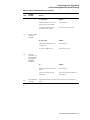
3 SLS Processes and Database Management
3.1 The SLS Server and Client Processes . . . . . . . . . . . . . . . . . . . . . . . . . . . . . . . . . . . . . . . . . . . . . . . . . . . . . 3-1
3.1.1
Client and Server Definitions . . . . . . . . . . . . . . . . . . . . . . . . . . . . . . . . . . . . . . . . . . . . . . . . . . . . . . . 3-1
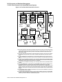
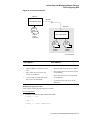
3.1.2
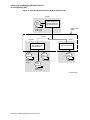
Basic Block Diagram of SLS Server and Client Processes . . . . . . . . . . . . . . . . . . . . . . . . . . . . . . . . . 3-2
3.2 The SLS Server Process in a OpenVMS Cluster System . . . . . . . . . . . . . . . . . . . . . . . . . . . . . . . . . . . . . . 3-3
3.2.1
Establishing the Active Server Node . . . . . . . . . . . . . . . . . . . . . . . . . . . . . . . . . . . . . . . . . . . . . . . . . . 3-3
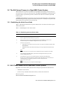
3.3 SLS Client Process in the OpenVMS Cluster System . . . . . . . . . . . . . . . . . . . . . . . . . . . . . . . . . . . . . . . . 3-3
3.3.1
Establishing a Client Connection on a OpenVMS Cluster System . . . . . . . . . . . . . . . . . . . . . . . . . . . 3-4
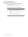
3.3.2
DFS Restrictions Using VMS Backup Utility . . . . . . . . . . . . . . . . . . . . . . . . . . . . . . . . . . . . . . . . . . . 3-7
3.4 How to Define the SLS Server Process . . . . . . . . . . . . . . . . . . . . . . . . . . . . . . . . . . . . . . . . . . . . . . . . . . . 3-9
3.5 How to Define the Client-Server Process Connection Timeout Value . . . . . . . . . . . . . . . . . . . . . . . . . . . 3-9
3.6 Optimizing SLS Database Files . . . . . . . . . . . . . . . . . . . . . . . . . . . . . . . . . . . . . . . . . . . . . . . . . . . . . . . . . 3-9
3.6.1
Recommended Minimum Optimization . . . . . . . . . . . . . . . . . . . . . . . . . . . . . . . . . . . . . . . . . . . . . . 3-10
iii
3.6.2
How to Optimize Files Using FDL . . . . . . . . . . . . . . . . . . . . . . . . . . . . . . . . . . . . . . . . . . . . . . . . . . 3-10
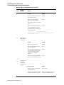
4 SLS Catalog Safety and Maintenance
4.1 Volume Database Location . . . . . . . . . . . . . . . . . . . . . . . . . . . . . . . . . . . . . . . . . . . . . . . . . . . . . . . . . . . . . 4-2
4.2 SLS History Files . . . . . . . . . . . . . . . . . . . . . . . . . . . . . . . . . . . . . . . . . . . . . . . . . . . . . . . . . . . . . . . . . . . . 4-2
4.2.1
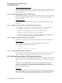
Creating SLS System History Files for System Backup Operations . . . . . . . . . . . . . . . . . . . . . . . . . . 4-3
4.2.1.1
Naming Your SLS System History File Sets . . . . . . . . . . . . . . . . . . . . . . . . . . . . . . . . . . . . . . . . 4-3
4.2.1.2
Defining SLS System History File Set Directories . . . . . . . . . . . . . . . . . . . . . . . . . . . . . . . . . . . 4-4
4.2.1.3
Rules for SLS System History File Set Names and Directories . . . . . . . . . . . . . . . . . . . . . . . . . 4-4
4.2.1.4
Example: SLS System History File Assignments . . . . . . . . . . . . . . . . . . . . . . . . . . . . . . . . . . . . 4-4
4.2.1.5
Characterizing SLS System History Files . . . . . . . . . . . . . . . . . . . . . . . . . . . . . . . . . . . . . . . . . . 4-4
4.2.2
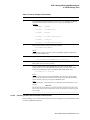
Defining Characteristics of SLS System History Sets . . . . . . . . . . . . . . . . . . . . . . . . . . . . . . . . . . . . 4-4
4.2.2.1
Determining the Space Required for SLS System History File Sets . . . . . . . . . . . . . . . . . . . . . . 4-5
4.2.2.2
History Records for Individual File Versions . . . . . . . . . . . . . . . . . . . . . . . . . . . . . . . . . . . . . . . 4-5
4.2.2.3
Declaring the Maximum File Name Size . . . . . . . . . . . . . . . . . . . . . . . . . . . . . . . . . . . . . . . . . . . 4-5
4.2.2.4
Declaring the Maximum Number of SLS System History Pointers Per File . . . . . . . . . . . . . . . . 4-6
4.2.2.5
Choosing to Store the Node Name in the Files File . . . . . . . . . . . . . . . . . . . . . . . . . . . . . . . . . . . 4-7
4.2.3
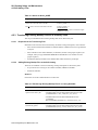
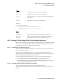
Transferring Existing Backup Files to SLS History Files . . . . . . . . . . . . . . . . . . . . . . . . . . . . . . . . . . 4-8
4.2.3.1
Requirements for Transferring Files . . . . . . . . . . . . . . . . . . . . . . . . . . . . . . . . . . . . . . . . . . . . . . 4-8
4.2.3.2
Adding Existing Backup Files to the SLS Catalog . . . . . . . . . . . . . . . . . . . . . . . . . . . . . . . . . . . 4-8
4.2.4
Creating SLS User History Files For User Backup Operations . . . . . . . . . . . . . . . . . . . . . . . . . . . . . 4-9
4.2.4.1
Considerations for User History Files . . . . . . . . . . . . . . . . . . . . . . . . . . . . . . . . . . . . . . . . . . . . . 4-9
4.2.4.2
How to Determine the SLS User History File Location . . . . . . . . . . . . . . . . . . . . . . . . . . . . . . . 4-9
4.3 Deleting Old SLS History Files . . . . . . . . . . . . . . . . . . . . . . . . . . . . . . . . . . . . . . . . . . . . . . . . . . . . . . . . 4-10
4.3.1
The CLEANUP Process . . . . . . . . . . . . . . . . . . . . . . . . . . . . . . . . . . . . . . . . . . . . . . . . . . . . . . . . . . 4-11
4.3.1.1
Cleaning SLS System History Files . . . . . . . . . . . . . . . . . . . . . . . . . . . . . . . . . . . . . . . . . . . . . . 4-11
4.3.1.2
The SYSCLN and CLEANUP Relationship . . . . . . . . . . . . . . . . . . . . . . . . . . . . . . . . . . . . . . . 4-11
4.3.1.3
Controlling the Cleanup Process . . . . . . . . . . . . . . . . . . . . . . . . . . . . . . . . . . . . . . . . . . . . . . . . 4-11
4.3.1.4
Setting the Days and Durations for Cleaning SLS History Files . . . . . . . . . . . . . . . . . . . . . . . . 4-12
4.3.2
SYSCLN Menu . . . . . . . . . . . . . . . . . . . . . . . . . . . . . . . . . . . . . . . . . . . . . . . . . . . . . . . . . . . . . . . . . 4-12
4.3.2.1
Start SYSCLN Processing . . . . . . . . . . . . . . . . . . . . . . . . . . . . . . . . . . . . . . . . . . . . . . . . . . . . . 4-14
4.3.2.2
Shutdown SYSCLN Processing . . . . . . . . . . . . . . . . . . . . . . . . . . . . . . . . . . . . . . . . . . . . . . . . . 4-15
4.3.2.3
Inquire SYSCLN Status . . . . . . . . . . . . . . . . . . . . . . . . . . . . . . . . . . . . . . . . . . . . . . . . . . . . . . . 4-16
4.3.2.4
Abort SYSCLN Processing . . . . . . . . . . . . . . . . . . . . . . . . . . . . . . . . . . . . . . . . . . . . . . . . . . . . 4-18
4.3.3
Delete User Histories . . . . . . . . . . . . . . . . . . . . . . . . . . . . . . . . . . . . . . . . . . . . . . . . . . . . . . . . . . . . . 4-18
4.4 Data Safety with the VMS Backup Utility . . . . . . . . . . . . . . . . . . . . . . . . . . . . . . . . . . . . . . . . . . . . . . . . 4-20
4.4.1
Volume and Magazine Database Device Failure . . . . . . . . . . . . . . . . . . . . . . . . . . . . . . . . . . . . . . . 4-20
4.4.2
SLS System History File Device Failure . . . . . . . . . . . . . . . . . . . . . . . . . . . . . . . . . . . . . . . . . . . . . . 4-21
4.4.3
Manually Updating the SLS System History Files . . . . . . . . . . . . . . . . . . . . . . . . . . . . . . . . . . . . . . 4-22
4.5 Data Safety with VAX RMS Journaling and the VMS Backup Utility . . . . . . . . . . . . . . . . . . . . . . . . . . 4-23
4.5.1
Implementing Data Safety with the VMS Backup Utility and VAX RMS Journaling . . . . . . . . . . . 4-23
4.5.2
VAX RMS Journal Device Failure . . . . . . . . . . . . . . . . . . . . . . . . . . . . . . . . . . . . . . . . . . . . . . . . . . 4-24
4.6 Data Safety with VAX Volume Shadowing Software . . . . . . . . . . . . . . . . . . . . . . . . . . . . . . . . . . . . . . . 4-24
5 Configuring SLS System Backup Operations
5.1 SLS System Backup Operations . . . . . . . . . . . . . . . . . . . . . . . . . . . . . . . . . . . . . . . . . . . . . . . . . . . . . . . . .
5.2 System Backup Command Files . . . . . . . . . . . . . . . . . . . . . . . . . . . . . . . . . . . . . . . . . . . . . . . . . . . . . . . . .
5.2.1
Creating SLS System Backup Command Files . . . . . . . . . . . . . . . . . . . . . . . . . . . . . . . . . . . . . . . . . .
5.2.2
System Backup Operations Using SYSBAK.TEMPLATE . . . . . . . . . . . . . . . . . . . . . . . . . . . . . . . .
5.2.3
Executing System Backup Operations . . . . . . . . . . . . . . . . . . . . . . . . . . . . . . . . . . . . . . . . . . . . . . . .
5.2.3.1
Running Manual Backup Operations . . . . . . . . . . . . . . . . . . . . . . . . . . . . . . . . . . . . . . . . . . . . . .
iv
5-1
5-2
5-3
5-3
5-8
5-8
5.2.3.2
Running Automatically Scheduled Backup Operations . . . . . . . . . . . . . . . . . . . . . . . . . . . . . . . . 5-8
5.3 Preparing for System Backup Operations . . . . . . . . . . . . . . . . . . . . . . . . . . . . . . . . . . . . . . . . . . . . . . . . . . 5-9
5.3.1
How to Define Automatic Scheduling Days . . . . . . . . . . . . . . . . . . . . . . . . . . . . . . . . . . . . . . . . . . . . 5-9
5.3.1.1
Symbols for Automatic Scheduling . . . . . . . . . . . . . . . . . . . . . . . . . . . . . . . . . . . . . . . . . . . . . . . 5-9
5.3.1.2
Specifying a Day of the Week . . . . . . . . . . . . . . . . . . . . . . . . . . . . . . . . . . . . . . . . . . . . . . . . . . . 5-9
5.3.1.3
Specifying a Day Offset into a Month . . . . . . . . . . . . . . . . . . . . . . . . . . . . . . . . . . . . . . . . . . . . 5-10
5.3.1.4
Specifying a Week Offset into a Month . . . . . . . . . . . . . . . . . . . . . . . . . . . . . . . . . . . . . . . . . . . 5-11
5.3.1.5
Specifying the Days to Run System Backup Operations . . . . . . . . . . . . . . . . . . . . . . . . . . . . . . 5-11
5.3.1.6
Specifying the Time of Day to Run System Backup Operations . . . . . . . . . . . . . . . . . . . . . . . . 5-13
5.3.1.7
Overriding the Default Queue with the Time Definition . . . . . . . . . . . . . . . . . . . . . . . . . . . . . . 5-13
5.3.1.8
Specifying the Node Executing the DCL SUBMIT Command . . . . . . . . . . . . . . . . . . . . . . . . . 5-13
5.3.1.9
Example: Automatic Scheduling Selection . . . . . . . . . . . . . . . . . . . . . . . . . . . . . . . . . . . . . . . . 5-14
5.3.1.10
Skipping an Automatically Scheduled System Backup Operation . . . . . . . . . . . . . . . . . . . . . . 5-14
5.3.2
Skipping Automatic System Backup Operations on Holidays . . . . . . . . . . . . . . . . . . . . . . . . . . . . . 5-15
5.3.2.1
HOLIDAYS.DAT Record Format . . . . . . . . . . . . . . . . . . . . . . . . . . . . . . . . . . . . . . . . . . . . . . . 5-15
5.3.2.2
Example: HOLIDAYS.DAT File . . . . . . . . . . . . . . . . . . . . . . . . . . . . . . . . . . . . . . . . . . . . . . . . 5-15
5.3.3
Preprocessing and Post-Processing Operations . . . . . . . . . . . . . . . . . . . . . . . . . . . . . . . . . . . . . . . . . 5-15
5.3.3.1
Execution Sequence for Preprocessing and Post-Processing Symbols . . . . . . . . . . . . . . . . . . . 5-15
5.3.3.2
Symbols Enabled for Preprocessing and Post-Processing . . . . . . . . . . . . . . . . . . . . . . . . . . . . . 5-16
5.3.3.3
Executing Another SBK Batch Job After the Backup Operation . . . . . . . . . . . . . . . . . . . . . . . 5-17
5.4 Defining the SLS System Backup Operation . . . . . . . . . . . . . . . . . . . . . . . . . . . . . . . . . . . . . . . . . . . . . . 5-18
5.4.1
The VMS BACKUP Command . . . . . . . . . . . . . . . . . . . . . . . . . . . . . . . . . . . . . . . . . . . . . . . . . . . . 5-18
5.4.1.1
Assignments to FILES_n . . . . . . . . . . . . . . . . . . . . . . . . . . . . . . . . . . . . . . . . . . . . . . . . . . . . . . 5-18
5.4.1.2
Assignments to QUALIFIERS and QUALIFIERS_n . . . . . . . . . . . . . . . . . . . . . . . . . . . . . . . . 5-18
5.4.1.3
Defining the Backup Privilege . . . . . . . . . . . . . . . . . . . . . . . . . . . . . . . . . . . . . . . . . . . . . . . . . . 5-24
5.4.1.4
Assignments to MNTFLAGS . . . . . . . . . . . . . . . . . . . . . . . . . . . . . . . . . . . . . . . . . . . . . . . . . . . 5-24
5.4.1.5
Assigning Additional Mount Actions . . . . . . . . . . . . . . . . . . . . . . . . . . . . . . . . . . . . . . . . . . . . 5-24
5.4.1.6
Save Set Name Symbol Descriptions . . . . . . . . . . . . . . . . . . . . . . . . . . . . . . . . . . . . . . . . . . . . . 5-25
5.4.1.7
Generating Save Set Names . . . . . . . . . . . . . . . . . . . . . . . . . . . . . . . . . . . . . . . . . . . . . . . . . . . . 5-27
5.4.1.8
Assigning the PROTECTION Symbols . . . . . . . . . . . . . . . . . . . . . . . . . . . . . . . . . . . . . . . . . . . 5-27
5.4.2
System Backup Volume Characteristics . . . . . . . . . . . . . . . . . . . . . . . . . . . . . . . . . . . . . . . . . . . . . . 5-27
5.4.2.1
Indicating the Type of Media Used for the Backup Operation . . . . . . . . . . . . . . . . . . . . . . . . . 5-28
5.4.2.2
Assigning the Volume Pool for the Backup Operation . . . . . . . . . . . . . . . . . . . . . . . . . . . . . . . 5-28
5.4.2.3
Assigning Backup Volume Density . . . . . . . . . . . . . . . . . . . . . . . . . . . . . . . . . . . . . . . . . . . . . . 5-28
5.4.2.4
Assigning the Backup Volume Size . . . . . . . . . . . . . . . . . . . . . . . . . . . . . . . . . . . . . . . . . . . . . . 5-28
5.4.3
System Backup Operator Intervention Policy . . . . . . . . . . . . . . . . . . . . . . . . . . . . . . . . . . . . . . . . . . 5-29
5.4.3.1
Example: Attended System Backup Assignments with Restrictions . . . . . . . . . . . . . . . . . . . . . 5-29
5.4.3.2
Example: Attended System Backup Assignments with Without Restrictions . . . . . . . . . . . . . . 5-29
5.4.3.3
Example: Unattended System Backup Assignments . . . . . . . . . . . . . . . . . . . . . . . . . . . . . . . . . 5-29
5.4.3.4
Acknowledging Loaded Volumes . . . . . . . . . . . . . . . . . . . . . . . . . . . . . . . . . . . . . . . . . . . . . . . 5-30
5.4.3.5
Allocating Volumes Prior to Running the System Backup Operation . . . . . . . . . . . . . . . . . . . . 5-30
5.4.3.6
Enabling SLS Software to Automatically Select Volumes . . . . . . . . . . . . . . . . . . . . . . . . . . . . 5-30
5.4.3.7
Allowable Values for AUTOSEL . . . . . . . . . . . . . . . . . . . . . . . . . . . . . . . . . . . . . . . . . . . . . . . 5-30
5.4.3.8
Recommended Procedure for Handling Volumes . . . . . . . . . . . . . . . . . . . . . . . . . . . . . . . . . . . 5-31
5.4.3.9
Handling Volume Label Mismatches During the System Backup Operation . . . . . . . . . . . . . . 5-31
5.4.3.10
Allowable CONTLOADOPT Values . . . . . . . . . . . . . . . . . . . . . . . . . . . . . . . . . . . . . . . . . . . . . 5-32
5.4.4
System Backup Media Resource Allocation . . . . . . . . . . . . . . . . . . . . . . . . . . . . . . . . . . . . . . . . . . . 5-32
5.4.4.1
Considerations for More Than One Save Set on One Volume . . . . . . . . . . . . . . . . . . . . . . . . . 5-32
5.4.4.2
Assigning Strings to the CONTINUE Symbol . . . . . . . . . . . . . . . . . . . . . . . . . . . . . . . . . . . . . 5-32
5.4.5
System Backup Volume Disposition . . . . . . . . . . . . . . . . . . . . . . . . . . . . . . . . . . . . . . . . . . . . . . . . . 5-33
5.4.5.1
Specifying Symbols for SLS System History Files . . . . . . . . . . . . . . . . . . . . . . . . . . . . . . . . . . 5-33
5.4.5.2
Naming Your SLS System History Set . . . . . . . . . . . . . . . . . . . . . . . . . . . . . . . . . . . . . . . . . . . 5-33
v
5.4.5.3
Naming the SLS System History Processing Queue . . . . . . . . . . . . . . . . . . . . . . . . . . . . . . . . .
5.4.5.4
Setting the Number of Days for Volume Retention . . . . . . . . . . . . . . . . . . . . . . . . . . . . . . . . . .
5.4.5.5
Setting Volume Off-Site and On-Site Dates . . . . . . . . . . . . . . . . . . . . . . . . . . . . . . . . . . . . . . .
5.4.5.6
Allowable OFFSITE_DATE and ONSITE_DATE Assignments . . . . . . . . . . . . . . . . . . . . . . .
5.4.5.7
Printing Volume Labels . . . . . . . . . . . . . . . . . . . . . . . . . . . . . . . . . . . . . . . . . . . . . . . . . . . . . . .
5.4.5.8
Allowable Assignments to TAPE_LABELS . . . . . . . . . . . . . . . . . . . . . . . . . . . . . . . . . . . . . . .
5.4.5.9
Assigning a Note to a Volume . . . . . . . . . . . . . . . . . . . . . . . . . . . . . . . . . . . . . . . . . . . . . . . . . .
5.4.6
System Backup Device Control . . . . . . . . . . . . . . . . . . . . . . . . . . . . . . . . . . . . . . . . . . . . . . . . . . . . .
5.4.6.1
Assigning the Backup Tape Device . . . . . . . . . . . . . . . . . . . . . . . . . . . . . . . . . . . . . . . . . . . . . .
5.4.6.2
Controlling the Number of Drives Used for a System Backup Operation . . . . . . . . . . . . . . . . .
5.4.6.3
How SLS Software Implements N_DRIVES During a System Backup Operation . . . . . . . . .
5.4.7
System Backup Status and Information Reporting . . . . . . . . . . . . . . . . . . . . . . . . . . . . . . . . . . . . . .
5.4.7.1
Job Notification . . . . . . . . . . . . . . . . . . . . . . . . . . . . . . . . . . . . . . . . . . . . . . . . . . . . . . . . . . . . .
5.4.7.2
Progress Reporting by Mail . . . . . . . . . . . . . . . . . . . . . . . . . . . . . . . . . . . . . . . . . . . . . . . . . . . .
5.4.7.3
Naming the Backup Log File . . . . . . . . . . . . . . . . . . . . . . . . . . . . . . . . . . . . . . . . . . . . . . . . . . .
5.4.7.4
Creating a Listing File Name . . . . . . . . . . . . . . . . . . . . . . . . . . . . . . . . . . . . . . . . . . . . . . . . . . .
5.4.7.5
Controlling Listing File Format . . . . . . . . . . . . . . . . . . . . . . . . . . . . . . . . . . . . . . . . . . . . . . . . .
5.4.7.6
Printing a Listing File . . . . . . . . . . . . . . . . . . . . . . . . . . . . . . . . . . . . . . . . . . . . . . . . . . . . . . . . .
5.5 Files Created During a System Backup Operation . . . . . . . . . . . . . . . . . . . . . . . . . . . . . . . . . . . . . . . . . .
5.5.1
Summary Files . . . . . . . . . . . . . . . . . . . . . . . . . . . . . . . . . . . . . . . . . . . . . . . . . . . . . . . . . . . . . . . . . .
5.5.2
Allowable SUMMARY_FILE Values . . . . . . . . . . . . . . . . . . . . . . . . . . . . . . . . . . . . . . . . . . . . . . .
5.5.3
System Backup Log Files . . . . . . . . . . . . . . . . . . . . . . . . . . . . . . . . . . . . . . . . . . . . . . . . . . . . . . . . .
5.5.4
Temporary History Files . . . . . . . . . . . . . . . . . . . . . . . . . . . . . . . . . . . . . . . . . . . . . . . . . . . . . . . . . .
5.5.5
Maintenance Log Files . . . . . . . . . . . . . . . . . . . . . . . . . . . . . . . . . . . . . . . . . . . . . . . . . . . . . . . . . . .
5-33
5-34
5-34
5-35
5-35
5-36
5-36
5-36
5-36
5-36
5-37
5-37
5-38
5-38
5-38
5-39
5-39
5-39
5-40
5-40
5-41
5-41
5-42
5-42
6 Performing Save Operations
6.1 Preparing for Save Operations . . . . . . . . . . . . . . . . . . . . . . . . . . . . . . . . . . . . . . . . . . . . . . . . . . . . . . . . . . 6-1
6.1.1
How SLS Performs Save Operations . . . . . . . . . . . . . . . . . . . . . . . . . . . . . . . . . . . . . . . . . . . . . . . . . 6-1
6.1.2
Types of Backup Operations . . . . . . . . . . . . . . . . . . . . . . . . . . . . . . . . . . . . . . . . . . . . . . . . . . . . . . . . 6-2
6.1.3
Controlling Data Saving Operations . . . . . . . . . . . . . . . . . . . . . . . . . . . . . . . . . . . . . . . . . . . . . . . . . . 6-2
6.1.3.1
Defining the Backup Operation Format . . . . . . . . . . . . . . . . . . . . . . . . . . . . . . . . . . . . . . . . . . . . 6-2
6.1.3.2
Restrictions Imposed by the ASCII and EBCDIC Formats . . . . . . . . . . . . . . . . . . . . . . . . . . . . . 6-3
6.1.3.3
Operator Save Screen Option Defaults . . . . . . . . . . . . . . . . . . . . . . . . . . . . . . . . . . . . . . . . . . . . 6-3
6.1.3.4
Setting the Operator Save Screen Defaults . . . . . . . . . . . . . . . . . . . . . . . . . . . . . . . . . . . . . . . . . 6-3
6.1.3.5
Setting the Default Volume Selection Method for User Save Operations . . . . . . . . . . . . . . . . . . 6-4
6.1.3.6
Defining the Backup Volume Protection . . . . . . . . . . . . . . . . . . . . . . . . . . . . . . . . . . . . . . . . . . . 6-4
6.1.3.7
Defining the Batch Queue Name for SLS Backup Operations . . . . . . . . . . . . . . . . . . . . . . . . . . 6-5
6.1.3.8
Notification of Completed Backup Operations . . . . . . . . . . . . . . . . . . . . . . . . . . . . . . . . . . . . . . 6-5
6.1.3.9
Supplying Default Volume Size for the STORAGE SAVE Command . . . . . . . . . . . . . . . . . . . . 6-5
6.1.3.10
Save Operations with Nonlibrary Volumes . . . . . . . . . . . . . . . . . . . . . . . . . . . . . . . . . . . . . . . . . 6-5
6.2 Performing Manual System Backups . . . . . . . . . . . . . . . . . . . . . . . . . . . . . . . . . . . . . . . . . . . . . . . . . . . . . 6-7
6.2.1
Accessing the Manual System Backup Menu Option . . . . . . . . . . . . . . . . . . . . . . . . . . . . . . . . . . . . . 6-7
6.2.2
Procedure For Using the Manual System Backup Option . . . . . . . . . . . . . . . . . . . . . . . . . . . . . . . . . . 6-7
6.3 Performing User Save Operations . . . . . . . . . . . . . . . . . . . . . . . . . . . . . . . . . . . . . . . . . . . . . . . . . . . . . . 6-18
6.3.1
User Interface . . . . . . . . . . . . . . . . . . . . . . . . . . . . . . . . . . . . . . . . . . . . . . . . . . . . . . . . . . . . . . . . . . 6-18
6.3.2
Save Screen Diagram . . . . . . . . . . . . . . . . . . . . . . . . . . . . . . . . . . . . . . . . . . . . . . . . . . . . . . . . . . . . 6-18
6.3.3
Procedure For Using the Save Screen Option . . . . . . . . . . . . . . . . . . . . . . . . . . . . . . . . . . . . . . . . . . 6-20
6.4 Performing Unattended Backup Operations . . . . . . . . . . . . . . . . . . . . . . . . . . . . . . . . . . . . . . . . . . . . . . . 6-27
6.4.1
How an Unattended System Backup Operation Works . . . . . . . . . . . . . . . . . . . . . . . . . . . . . . . . . . 6-27
6.4.2
Modifying System Backup Procedures . . . . . . . . . . . . . . . . . . . . . . . . . . . . . . . . . . . . . . . . . . . . . . . 6-28
6.4.3
Performing Unattended System Backups . . . . . . . . . . . . . . . . . . . . . . . . . . . . . . . . . . . . . . . . . . . . . 6-29
6.4.4
Performing Unattended System Backups Using Preallocated . . . . . . . . . . . . . . . . . . . . . . . . . . . . . . 6-30
vi
7 Restoring Files and Disks
7.1 Restoring Data . . . . . . . . . . . . . . . . . . . . . . . . . . . . . . . . . . . . . . . . . . . . . . . . . . . . . . . . . . . . . . . . . . . . . .
7.1.1
Defining the Restore Operation Queue . . . . . . . . . . . . . . . . . . . . . . . . . . . . . . . . . . . . . . . . . . . . . . . .
7.1.2
Setting Operator Restore Screen Option Defaults . . . . . . . . . . . . . . . . . . . . . . . . . . . . . . . . . . . . . . . .
7.1.3
Notification when Restore Is Finished . . . . . . . . . . . . . . . . . . . . . . . . . . . . . . . . . . . . . . . . . . . . . . . .
7.1.4
Controlling Data Restore Operations . . . . . . . . . . . . . . . . . . . . . . . . . . . . . . . . . . . . . . . . . . . . . . . . .
7.1.5
Restore Operations with Nonlibrary Volumes . . . . . . . . . . . . . . . . . . . . . . . . . . . . . . . . . . . . . . . . . .
7.2 Restoring a Disk . . . . . . . . . . . . . . . . . . . . . . . . . . . . . . . . . . . . . . . . . . . . . . . . . . . . . . . . . . . . . . . . . . . . .
7.3 Restoring a File or Group of Files . . . . . . . . . . . . . . . . . . . . . . . . . . . . . . . . . . . . . . . . . . . . . . . . . . . . . . .
7.3.1
Requesting a Restore Operation . . . . . . . . . . . . . . . . . . . . . . . . . . . . . . . . . . . . . . . . . . . . . . . . . . . . .
7.3.2
Using the Restore Screen . . . . . . . . . . . . . . . . . . . . . . . . . . . . . . . . . . . . . . . . . . . . . . . . . . . . . . . . . . .
7-1
7-1
7-1
7-2
7-2
7-2
7-3
7-6
7-6
7-6
8 Using RMU Backup and Restore with SLS
8.1 Overview of RMU Backup and Restore Support . . . . . . . . . . . . . . . . . . . . . . . . . . . . . . . . . . . . . . . . . . . . 8-1
8.2 Using RMU and SLS Together . . . . . . . . . . . . . . . . . . . . . . . . . . . . . . . . . . . . . . . . . . . . . . . . . . . . . . . . . . 8-1
8.2.1
Oracle Rdb Minimum Version . . . . . . . . . . . . . . . . . . . . . . . . . . . . . . . . . . . . . . . . . . . . . . . . . . . . . . 8-2
8.2.2
Types of System Backup Operations . . . . . . . . . . . . . . . . . . . . . . . . . . . . . . . . . . . . . . . . . . . . . . . . . 8-2
8.3 Overview of Database System Backup Processing . . . . . . . . . . . . . . . . . . . . . . . . . . . . . . . . . . . . . . . . . . 8-2
8.4 Defining Database System Backup Operations . . . . . . . . . . . . . . . . . . . . . . . . . . . . . . . . . . . . . . . . . . . . . 8-2
8.4.1
Identifying Database Backup History Sets in TAPESTART.COM . . . . . . . . . . . . . . . . . . . . . . . . . . 8-3
8.4.2
Locating the Database System Backup Command File . . . . . . . . . . . . . . . . . . . . . . . . . . . . . . . . . . . 8-4
8.4.3
Identifying Backup Operation Type . . . . . . . . . . . . . . . . . . . . . . . . . . . . . . . . . . . . . . . . . . . . . . . . . . 8-4
8.4.4
Modifying Existing Symbols . . . . . . . . . . . . . . . . . . . . . . . . . . . . . . . . . . . . . . . . . . . . . . . . . . . . . . . . 8-5
8.4.5
Using QUALIFIERS_n . . . . . . . . . . . . . . . . . . . . . . . . . . . . . . . . . . . . . . . . . . . . . . . . . . . . . . . . . . . . 8-6
8.4.6
Nullifying Existing Symbols . . . . . . . . . . . . . . . . . . . . . . . . . . . . . . . . . . . . . . . . . . . . . . . . . . . . . . . . 8-6
8.4.7
Compaction issue with RMU Backup on VMS 7.2-1 and 7.3 . . . . . . . . . . . . . . . . . . . . . . . . . . . . . . 8-6
8.4.8
Specifying Oracle Rdb Software Version . . . . . . . . . . . . . . . . . . . . . . . . . . . . . . . . . . . . . . . . . . . . . . 8-7
8.5 Running Database System Backups . . . . . . . . . . . . . . . . . . . . . . . . . . . . . . . . . . . . . . . . . . . . . . . . . . . . . . 8-7
8.5.1
Running Database Backups Automatically . . . . . . . . . . . . . . . . . . . . . . . . . . . . . . . . . . . . . . . . . . . . . 8-7
8.5.2
Running Database Backups Manually . . . . . . . . . . . . . . . . . . . . . . . . . . . . . . . . . . . . . . . . . . . . . . . . . 8-7
8.5.2.1
Using the DCL Command Interface . . . . . . . . . . . . . . . . . . . . . . . . . . . . . . . . . . . . . . . . . . . . . . . 8-7
8.5.2.2
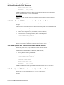
Using the Operator Menu Interface . . . . . . . . . . . . . . . . . . . . . . . . . . . . . . . . . . . . . . . . . . . . . . . 8-7
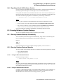
8.6 Using Volume Reports to Identify Database Backups . . . . . . . . . . . . . . . . . . . . . . . . . . . . . . . . . . . . . . . . 8-8
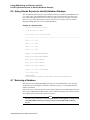
8.7 Restoring a Database . . . . . . . . . . . . . . . . . . . . . . . . . . . . . . . . . . . . . . . . . . . . . . . . . . . . . . . . . . . . . . . . . 8-8
8.7.1
Before Restoring an Oracle Rdb Database . . . . . . . . . . . . . . . . . . . . . . . . . . . . . . . . . . . . . . . . . . . . . 8-9
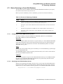
8.7.1.1
Designating an Oracle RMU Restore Operation . . . . . . . . . . . . . . . . . . . . . . . . . . . . . . . . . . . . . 8-9
8.7.1.2
Specifying Oracle Rdb Software Version . . . . . . . . . . . . . . . . . . . . . . . . . . . . . . . . . . . . . . . . . . 8-9
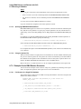
8.7.1.3
Specifying RMU/RESTORE Qualifiers . . . . . . . . . . . . . . . . . . . . . . . . . . . . . . . . . . . . . . . . . . . 8-10
8.7.1.4
Using an Options File . . . . . . . . . . . . . . . . . . . . . . . . . . . . . . . . . . . . . . . . . . . . . . . . . . . . . . . . . 8-10
8.7.2
Example Oracle RMU Restore Scenarios . . . . . . . . . . . . . . . . . . . . . . . . . . . . . . . . . . . . . . . . . . . . . 8-10
8.7.2.1
Full Restore of a Single File Database . . . . . . . . . . . . . . . . . . . . . . . . . . . . . . . . . . . . . . . . . . . . 8-10
8.7.2.2
Full Restore of Multiple File Database . . . . . . . . . . . . . . . . . . . . . . . . . . . . . . . . . . . . . . . . . . . 8-11
8.7.2.3
Full Restore of an Area of a Multiple File Database . . . . . . . . . . . . . . . . . . . . . . . . . . . . . . . . . 8-12
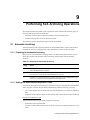
9 Performing SLS Archiving Operations
9.1 Automatic Archiving . . . . . . . . . . . . . . . . . . . . . . . . . . . . . . . . . . . . . . . . . . . . . . . . . . . . . . . . . . . . . . . . .
9.1.1
Preparing for Automatic Archiving . . . . . . . . . . . . . . . . . . . . . . . . . . . . . . . . . . . . . . . . . . . . . . . . . . .
9.1.2
Setting File Retention and Expiration Times . . . . . . . . . . . . . . . . . . . . . . . . . . . . . . . . . . . . . . . . . . .
9.1.2.1
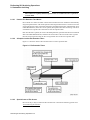
How the File Retention Time Works . . . . . . . . . . . . . . . . . . . . . . . . . . . . . . . . . . . . . . . . . . . . . .
9.1.2.2
A Graphic Look at File Retention Times . . . . . . . . . . . . . . . . . . . . . . . . . . . . . . . . . . . . . . . . . . .
9-1
9-1
9-1
9-2
9-2
vii
9.1.2.3
Special Cases of File Access . . . . . . . . . . . . . . . . . . . . . . . . . . . . . . . . . . . . . . . . . . . . . . . . . . . . 9-2
9.1.2.4
Rules for Applying the File Retention Time with the SET VOLUME Command . . . . . . . . . . . 9-3
9.1.2.5
How to Set the File Retention Time . . . . . . . . . . . . . . . . . . . . . . . . . . . . . . . . . . . . . . . . . . . . . . . 9-3
9.1.2.6
How to Set Expiration Times for Files . . . . . . . . . . . . . . . . . . . . . . . . . . . . . . . . . . . . . . . . . . . . . 9-4
9.1.2.7
How to Determine a File's Expiration Date . . . . . . . . . . . . . . . . . . . . . . . . . . . . . . . . . . . . . . . . . 9-4
9.1.3
Controlling Automatic Archiving . . . . . . . . . . . . . . . . . . . . . . . . . . . . . . . . . . . . . . . . . . . . . . . . . . . . 9-4
9.2 Standby Archiving . . . . . . . . . . . . . . . . . . . . . . . . . . . . . . . . . . . . . . . . . . . . . . . . . . . . . . . . . . . . . . . . . . . 9-6
9.2.1
Advantages of Standby Archiving . . . . . . . . . . . . . . . . . . . . . . . . . . . . . . . . . . . . . . . . . . . . . . . . . . . . 9-7
9.2.2
How Standby Archiving Works . . . . . . . . . . . . . . . . . . . . . . . . . . . . . . . . . . . . . . . . . . . . . . . . . . . . . 9-7
9.2.3
How Standby Archiving Executes Save Requests . . . . . . . . . . . . . . . . . . . . . . . . . . . . . . . . . . . . . . . 9-8
9.2.4
How Standby Archiving Uses .ARKIVE Files . . . . . . . . . . . . . . . . . . . . . . . . . . . . . . . . . . . . . . . . . . 9-8
9.2.5
Editing TAPESTART.COM for Standby Archiving . . . . . . . . . . . . . . . . . . . . . . . . . . . . . . . . . . . . . . 9-8
9.2.5.1
Defining Standby Archiving Log File Location . . . . . . . . . . . . . . . . . . . . . . . . . . . . . . . . . . . . . 9-8
9.2.5.2
Setting the Standby Archiving Interval . . . . . . . . . . . . . . . . . . . . . . . . . . . . . . . . . . . . . . . . . . . . 9-8
9.2.5.3
Defining the Default Archive Class . . . . . . . . . . . . . . . . . . . . . . . . . . . . . . . . . . . . . . . . . . . . . . . 9-9
9.2.5.4
Alternate Methods for Defining the Default Archive Class . . . . . . . . . . . . . . . . . . . . . . . . . . . . . 9-9
9.2.6
Standby Archive Operator Menu Option . . . . . . . . . . . . . . . . . . . . . . . . . . . . . . . . . . . . . . . . . . . . . . 9-9
9.2.6.1
Standby Archive Menu Options . . . . . . . . . . . . . . . . . . . . . . . . . . . . . . . . . . . . . . . . . . . . . . . . . 9-10
9.2.6.2
Starting Up and Shutting Down the Standby Archiving Process . . . . . . . . . . . . . . . . . . . . . . . . 9-11
9.2.6.3
Before You Begin . . . . . . . . . . . . . . . . . . . . . . . . . . . . . . . . . . . . . . . . . . . . . . . . . . . . . . . . . . . . 9-11
9.2.6.4
Starting Up Standby Archive From the Operator Menu . . . . . . . . . . . . . . . . . . . . . . . . . . . . . . 9-12
9.2.6.5
Shutting Down Standby Archive From the Operator Menu . . . . . . . . . . . . . . . . . . . . . . . . . . . 9-14
9.2.6.6
Inquire Pending Jobs From the Operator Menu . . . . . . . . . . . . . . . . . . . . . . . . . . . . . . . . . . . . . 9-15
9.2.6.7
Aborting Standby Archive . . . . . . . . . . . . . . . . . . . . . . . . . . . . . . . . . . . . . . . . . . . . . . . . . . . . . 9-16
9.2.6.8
How to Interrupt the Standby Archive Process . . . . . . . . . . . . . . . . . . . . . . . . . . . . . . . . . . . . . 9-17
9.2.7
Establishing Archive Classes and Enabling User Access . . . . . . . . . . . . . . . . . . . . . . . . . . . . . . . . . 9-17
9.2.7.1
Archive Class Naming Conventions . . . . . . . . . . . . . . . . . . . . . . . . . . . . . . . . . . . . . . . . . . . . . 9-17
9.2.7.2
Authorizing Class Access For a User From The Operator Menu . . . . . . . . . . . . . . . . . . . . . . . 9-18
9.2.8
Performing Save Operations Using Standby Archiving . . . . . . . . . . . . . . . . . . . . . . . . . . . . . . . . . . 9-21
9.2.8.1
Standby Archiving Performed From the User Menu Save Screen . . . . . . . . . . . . . . . . . . . . . . . 9-21
9.2.8.2
Standby Archiving Performed Using DCL . . . . . . . . . . . . . . . . . . . . . . . . . . . . . . . . . . . . . . . . 9-21
10 Generating SLS Reports
10.1Operator Menu: Inquire Pending Jobs . . . . . . . . . . . . . . . . . . . . . . . . . . . . . . . . . . . . . . . . . . . . . . . . . . . 10-1
10.2User Menu: Report of Files on User Backups . . . . . . . . . . . . . . . . . . . . . . . . . . . . . . . . . . . . . . . . . . . . . 10-2
10.3User Menu: Report of Files on System Backups . . . . . . . . . . . . . . . . . . . . . . . . . . . . . . . . . . . . . . . . . . . 10-2
A System Backup Command File QuickReference
A.1
A.2
A.3
A.4
A.5
A.6
A.7
A.8
Symbols for System Backup Control . . . . . . . . . . . . . . . . . . . . . . . . . . . . . . . . . . . . . . . . . . . . . . . . . . . . . A-1
Symbols for System Backup Type . . . . . . . . . . . . . . . . . . . . . . . . . . . . . . . . . . . . . . . . . . . . . . . . . . . . . . . A-2
Symbols for System Backup Volume Characteristics . . . . . . . . . . . . . . . . . . . . . . . . . . . . . . . . . . . . . . . . A-3
Symbols for System Backup Operator Intervention . . . . . . . . . . . . . . . . . . . . . . . . . . . . . . . . . . . . . . . . . . A-4
Symbols for System Backup Resource Allocation . . . . . . . . . . . . . . . . . . . . . . . . . . . . . . . . . . . . . . . . . . . A-5
Symbols for System Backup Volume Disposition . . . . . . . . . . . . . . . . . . . . . . . . . . . . . . . . . . . . . . . . . . . A-5
Symbols for System Backup Device Control . . . . . . . . . . . . . . . . . . . . . . . . . . . . . . . . . . . . . . . . . . . . . . . A-6
Symbols for System Backup Status and Information . . . . . . . . . . . . . . . . . . . . . . . . . . . . . . . . . . . . . . . . . A-7
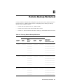
B Remote Backup Worksheet
11 Introduction to Media and Device Management Services
viii
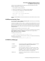
11.1What MDMS Provides . . . . . . . . . . . . . . . . . . . . . . . . . . . . . . . . . . . . . . . . . . . . . . . . . . . . . . . . . . . . . . .
11.2Where MDMS Stores Information . . . . . . . . . . . . . . . . . . . . . . . . . . . . . . . . . . . . . . . . . . . . . . . . . . . . . .
11.3MDMS User Interfaces . . . . . . . . . . . . . . . . . . . . . . . . . . . . . . . . . . . . . . . . . . . . . . . . . . . . . . . . . . . . . . .
11.4Who Interacts with MDMS . . . . . . . . . . . . . . . . . . . . . . . . . . . . . . . . . . . . . . . . . . . . . . . . . . . . . . . . . . .
11-1
11-2
11-2
11-2
12 Configuring for Media Management
12.1Understanding TAPESTART.COM Symbols and Definitions . . . . . . . . . . . . . . . . . . . . . . . . . . . . . . . . 12-1
12.1.1 Basic MDMS Symbols . . . . . . . . . . . . . . . . . . . . . . . . . . . . . . . . . . . . . . . . . . . . . . . . . . . . . . . . . . . 12-1
12.1.2 Media Triplets . . . . . . . . . . . . . . . . . . . . . . . . . . . . . . . . . . . . . . . . . . . . . . . . . . . . . . . . . . . . . . . . . . 12-3
12.1.2.1
Guidelines for Media Triplet Assignments . . . . . . . . . . . . . . . . . . . . . . . . . . . . . . . . . . . . . . . . 12-4
12.1.2.2
Default Media Triplet . . . . . . . . . . . . . . . . . . . . . . . . . . . . . . . . . . . . . . . . . . . . . . . . . . . . . . . . . 12-4
12.1.2.3
Creating Default Media Triplets . . . . . . . . . . . . . . . . . . . . . . . . . . . . . . . . . . . . . . . . . . . . . . . . 12-5
12.1.2.4
Inserting Media Triplets Into TAPESTART.COM . . . . . . . . . . . . . . . . . . . . . . . . . . . . . . . . . . 12-6
12.1.2.5
Media Triplets for Tape Jukebox Devices . . . . . . . . . . . . . . . . . . . . . . . . . . . . . . . . . . . . . . . . . 12-7
12.1.3 Volume Management Symbols . . . . . . . . . . . . . . . . . . . . . . . . . . . . . . . . . . . . . . . . . . . . . . . . . . . . . 12-7
12.1.3.1
Volume Management Privileges Symbols . . . . . . . . . . . . . . . . . . . . . . . . . . . . . . . . . . . . . . . . . 12-9
12.1.3.2
Volume Loading Symbol . . . . . . . . . . . . . . . . . . . . . . . . . . . . . . . . . . . . . . . . . . . . . . . . . . . . . 12-10
12.1.4 Operator Terminal Control Symbols . . . . . . . . . . . . . . . . . . . . . . . . . . . . . . . . . . . . . . . . . . . . . . . . 12-10
12.1.5 Drive Control Symbols . . . . . . . . . . . . . . . . . . . . . . . . . . . . . . . . . . . . . . . . . . . . . . . . . . . . . . . . . . 12-12
12.1.6 Miscellaneous Symbol Assignments . . . . . . . . . . . . . . . . . . . . . . . . . . . . . . . . . . . . . . . . . . . . . . . . 12-12
13 Managing Jukebox Devices Using MDMS
13.1Working with Magnetic Tape Jukeboxes . . . . . . . . . . . . . . . . . . . . . . . . . . . . . . . . . . . . . . . . . . . . . . . . . 13-1
13.1.1 Customizing TAPESTART.COM for Robotically Controlled Magnetic Tape Jukebox Devices . . 13-2
13.1.1.1
Required Naming Conventions . . . . . . . . . . . . . . . . . . . . . . . . . . . . . . . . . . . . . . . . . . . . . . . . . 13-2
13.1.1.2
Required Media Triplets . . . . . . . . . . . . . . . . . . . . . . . . . . . . . . . . . . . . . . . . . . . . . . . . . . . . . . . 13-3
13.1.2 Determining Your Hardware Configuration . . . . . . . . . . . . . . . . . . . . . . . . . . . . . . . . . . . . . . . . . . . 13-3
13.1.3 Direct Connect DSSI Devices . . . . . . . . . . . . . . . . . . . . . . . . . . . . . . . . . . . . . . . . . . . . . . . . . . . . . . 13-4
13.1.3.1
Customizing TAPESTART.COM for Direct DSSI Devices . . . . . . . . . . . . . . . . . . . . . . . . . . . 13-4
13.1.4 Direct Connect SCSI Devices . . . . . . . . . . . . . . . . . . . . . . . . . . . . . . . . . . . . . . . . . . . . . . . . . . . . . . 13-5
13.1.4.1
Creating a Tape Robot Unit . . . . . . . . . . . . . . . . . . . . . . . . . . . . . . . . . . . . . . . . . . . . . . . . . . . . 13-5
13.1.4.2
Customizing TAPESTART.COM Symbols for a Direct Connect SCSI Device . . . . . . . . . . . . 13-6
13.1.5 Controller-Connected SCSI Devices . . . . . . . . . . . . . . . . . . . . . . . . . . . . . . . . . . . . . . . . . . . . . . . . . 13-6
13.1.5.1
Using SCSI Tape Jukeboxes Connected to an HSC Controller . . . . . . . . . . . . . . . . . . . . . . . . . 13-7
13.1.5.2
Using A SCSI Tape Jukeboxes Connected to an HSD or HSJ Controller . . . . . . . . . . . . . . . . . 13-7
13.1.5.3
Customizing TAPESTART.COM Symbols for a Controller-Connected SCSI Device . . . . . . . 13-9
13.1.5.4
TL810- and TL820-Type Devices with Multiple Drives . . . . . . . . . . . . . . . . . . . . . . . . . . . . . . 13-9
13.1.6 Defining Multiple Tape Jukebox Symbols and Associated Media Triplets . . . . . . . . . . . . . . . . . . 13-10
13.1.7 Using a Cleaning Cartridge in a Managed Jukebox . . . . . . . . . . . . . . . . . . . . . . . . . . . . . . . . . . . . 13-11
13.2Using TMSCP-Served Tape Devices . . . . . . . . . . . . . . . . . . . . . . . . . . . . . . . . . . . . . . . . . . . . . . . . . . . 13-12
13.3Using Magazines with Tape Jukeboxes in MDMS . . . . . . . . . . . . . . . . . . . . . . . . . . . . . . . . . . . . . . . . 13-12
13.3.1 Adding a Magazine . . . . . . . . . . . . . . . . . . . . . . . . . . . . . . . . . . . . . . . . . . . . . . . . . . . . . . . . . . . . . 13-13
13.3.2 Manually Binding Volumes to a Magazine . . . . . . . . . . . . . . . . . . . . . . . . . . . . . . . . . . . . . . . . . . . 13-14
13.3.3 Automatically Binding Volumes to a Magazine . . . . . . . . . . . . . . . . . . . . . . . . . . . . . . . . . . . . . . . 13-16
13.3.4 Using Multiple Magazines in Single and Multitower Jukeboxes. . . . . . . . . . . . . . . . . . . . . . . . . . . 13-17
13.3.4.1
Bin Numbering Convention . . . . . . . . . . . . . . . . . . . . . . . . . . . . . . . . . . . . . . . . . . . . . . . . . . . 13-17
13.3.4.2
How to Calculate the Slot Numbers When Using Multiple Magazines . . . . . . . . . . . . . . . . . . 13-17
13.3.5 Loading and Unloading Volumes in a Jukebox . . . . . . . . . . . . . . . . . . . . . . . . . . . . . . . . . . . . . . . 13-18
13.3.6 Physically Removing a Magazine from a Jukebox . . . . . . . . . . . . . . . . . . . . . . . . . . . . . . . . . . . . . 13-18
13.3.7 Removing Magazines from Use . . . . . . . . . . . . . . . . . . . . . . . . . . . . . . . . . . . . . . . . . . . . . . . . . . . 13-18
13.3.8 Removing a Magazine from the MDMS Magazine Database . . . . . . . . . . . . . . . . . . . . . . . . . . . . . 13-19
ix
13.3.9 Showing Magazine Information . . . . . . . . . . . . . . . . . . . . . . . . . . . . . . . . . . . . . . . . . . . . . . . . . . .
13.3.10 Showing Volumes in a Magazine . . . . . . . . . . . . . . . . . . . . . . . . . . . . . . . . . . . . . . . . . . . . . . . . . .
13.3.11 Using Magnetic Tape Jukeboxes with Individual Cartridges . . . . . . . . . . . . . . . . . . . . . . . . . . . . .
13.3.11.1
Importing a Cartridge Into a TL810 Jukebox . . . . . . . . . . . . . . . . . . . . . . . . . . . . . . . . . . . . . .
13.4Operating Tape Jukeboxes as Stack Loaders . . . . . . . . . . . . . . . . . . . . . . . . . . . . . . . . . . . . . . . . . . . . .
13.5Resolving Jukebox Problems . . . . . . . . . . . . . . . . . . . . . . . . . . . . . . . . . . . . . . . . . . . . . . . . . . . . . . . . .
13.5.1 Separating Software and Hardware Tape Movement Requests . . . . . . . . . . . . . . . . . . . . . . . . . . .
13.5.2 Identifying Unrecoverable Robotic Control Errors . . . . . . . . . . . . . . . . . . . . . . . . . . . . . . . . . . . . .
13.6Using a TL800 Class Jukebox . . . . . . . . . . . . . . . . . . . . . . . . . . . . . . . . . . . . . . . . . . . . . . . . . . . . . . . .
13.6.1 TL800 Jukebox Features and What They Mean . . . . . . . . . . . . . . . . . . . . . . . . . . . . . . . . . . . . . . .
13.6.2 Recommended Hardware Settings . . . . . . . . . . . . . . . . . . . . . . . . . . . . . . . . . . . . . . . . . . . . . . . . .
13.6.3 Using Uncataloged Media with a TL800 Class Jukebox . . . . . . . . . . . . . . . . . . . . . . . . . . . . . . . .
13.6.4 Using Cataloged Media with a TL800 Class Jukebox . . . . . . . . . . . . . . . . . . . . . . . . . . . . . . . . . .
13.7Working with DCSC-Controlled Robotic Silos . . . . . . . . . . . . . . . . . . . . . . . . . . . . . . . . . . . . . . . . . . .
13.7.1 Customizing TAPESTART.COM for DCSC-Controlled Silos . . . . . . . . . . . . . . . . . . . . . . . . . . .
13.7.1.1
DCSC_DRIVES Symbol . . . . . . . . . . . . . . . . . . . . . . . . . . . . . . . . . . . . . . . . . . . . . . . . . . . . .
13.7.1.2
Media Triplet for DCSC Tape Devices . . . . . . . . . . . . . . . . . . . . . . . . . . . . . . . . . . . . . . . . . .
13.7.1.3
DCSC_n_NODE Symbol . . . . . . . . . . . . . . . . . . . . . . . . . . . . . . . . . . . . . . . . . . . . . . . . . . . . .
13.7.2 MDMS Functions Associated with DCSC-Controlled Silos . . . . . . . . . . . . . . . . . . . . . . . . . . . . . .
13.7.2.1
STORAGE Commands for Silos . . . . . . . . . . . . . . . . . . . . . . . . . . . . . . . . . . . . . . . . . . . . . . .
13.7.3 Identifying the Volumes in a DCSC-Controlled Silo . . . . . . . . . . . . . . . . . . . . . . . . . . . . . . . . . . .
13.7.4 13.7.4 Adding Volumes to a DCSC-Controlled Silo . . . . . . . . . . . . . . . . . . . . . . . . . . . . . . . . . . .
13.7.5 Removing Volumes from a DCSC-Controlled Silo . . . . . . . . . . . . . . . . . . . . . . . . . . . . . . . . . . . .
13.7.6 ACS Management Menu . . . . . . . . . . . . . . . . . . . . . . . . . . . . . . . . . . . . . . . . . . . . . . . . . . . . . . . . .
13.7.6.1
ACS Management Menu: Inventory Volume Series . . . . . . . . . . . . . . . . . . . . . . . . . . . . . . . .
13.7.6.2
Inventory Volume Series Screen Diagram . . . . . . . . . . . . . . . . . . . . . . . . . . . . . . . . . . . . . . . .
13.7.6.3
How To Use The Inventory Volumes Series Option . . . . . . . . . . . . . . . . . . . . . . . . . . . . . . . .
13.7.6.4
ACS Management Menu: Import Volume(s) . . . . . . . . . . . . . . . . . . . . . . . . . . . . . . . . . . . . . .
13.7.6.5
Import Volume(s) Screen Diagram . . . . . . . . . . . . . . . . . . . . . . . . . . . . . . . . . . . . . . . . . . . . .
13.7.6.6
How To Use The Import Volume Option . . . . . . . . . . . . . . . . . . . . . . . . . . . . . . . . . . . . . . . .
13.7.6.7
ACS Management Menu: Initialize Volume Series . . . . . . . . . . . . . . . . . . . . . . . . . . . . . . . . .
13.7.6.8
13.7.6.8 Initialize Volume Series Screen Diagram . . . . . . . . . . . . . . . . . . . . . . . . . . . . . . . . .
13.7.6.9
How To Use The Initialize Volume Series Option . . . . . . . . . . . . . . . . . . . . . . . . . . . . . . . . .
13.7.6.10
ACS Management Menu: Load Volume Onto Drive . . . . . . . . . . . . . . . . . . . . . . . . . . . . . . . .
13.7.6.11
Load Volume Onto Drive Screen Diagram . . . . . . . . . . . . . . . . . . . . . . . . . . . . . . . . . . . . . . .
13.7.6.12
How To Use The Load Volume Onto Drive Option . . . . . . . . . . . . . . . . . . . . . . . . . . . . . . . .
13.7.6.13
ACS Management Menu: Unload Drive . . . . . . . . . . . . . . . . . . . . . . . . . . . . . . . . . . . . . . . . .
13.7.6.14
Unload Drive Screen Diagram . . . . . . . . . . . . . . . . . . . . . . . . . . . . . . . . . . . . . . . . . . . . . . . . .
13.7.6.15
How To Use The Unload Drive Option . . . . . . . . . . . . . . . . . . . . . . . . . . . . . . . . . . . . . . . . . .
13.7.6.16
ACS Management Menu: Unload Volume . . . . . . . . . . . . . . . . . . . . . . . . . . . . . . . . . . . . . . .
13.7.6.17
Unload Volume Screen Diagram . . . . . . . . . . . . . . . . . . . . . . . . . . . . . . . . . . . . . . . . . . . . . . .
13.7.6.18
How To Use The Unload Volume Option . . . . . . . . . . . . . . . . . . . . . . . . . . . . . . . . . . . . . . . .
13.7.6.19
ACS Management Menu: Export Volume(s) . . . . . . . . . . . . . . . . . . . . . . . . . . . . . . . . . . . . . .
13.7.6.20
Export Volume(s) Screen Diagram . . . . . . . . . . . . . . . . . . . . . . . . . . . . . . . . . . . . . . . . . . . . .
13.7.6.21
How To Use The Export Volume(s) Option . . . . . . . . . . . . . . . . . . . . . . . . . . . . . . . . . . . . . .
13-19
13-20
13-20
13-21
13-22
13-22
13-22
13-23
13-23
13-23
13-23
13-24
13-25
13-26
13-27
13-27
13-27
13-28
13-28
13-28
13-28
13-28
13-28
13-29
13-29
13-29
13-30
13-31
13-31
13-32
13-34
13-34
13-34
13-37
13-37
13-37
13-38
13-38
13-39
13-40
13-40
13-40
13-41
13-41
13-41
14 Connecting and Managing Remote Devices
14.1The RDF Installation . . . . . . . . . . . . . . . . . . . . . . . . . . . . . . . . . . . . . . . . . . . . . . . . . . . . . . . . . . . . . . . .
14.2Configuring RDF . . . . . . . . . . . . . . . . . . . . . . . . . . . . . . . . . . . . . . . . . . . . . . . . . . . . . . . . . . . . . . . . . . .
14.2.1 Configuration Scenarios . . . . . . . . . . . . . . . . . . . . . . . . . . . . . . . . . . . . . . . . . . . . . . . . . . . . . . . . . .
14.2.1.1
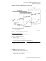
Scenario 1-Single Remote Device . . . . . . . . . . . . . . . . . . . . . . . . . . . . . . . . . . . . . . . . . . . . . . .
14.2.1.2
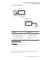
Scenario 2-Local Area Network . . . . . . . . . . . . . . . . . . . . . . . . . . . . . . . . . . . . . . . . . . . . . . . . .
x
14-1
14-1
14-4
14-4
14-6
14.2.1.3
Scenario 3-Two-Way Remote Backup Operations . . . . . . . . . . . . . . . . . . . . . . . . . . . . . . . . . . 14-8
14.2.1.4
Scenario 4-Multiple Remote Nodes . . . . . . . . . . . . . . . . . . . . . . . . . . . . . . . . . . . . . . . . . . . . . 14-11
14.3Using RDF with MDMS . . . . . . . . . . . . . . . . . . . . . . . . . . . . . . . . . . . . . . . . . . . . . . . . . . . . . . . . . . . . . 14-14
14.3.1 Restrictions: Using RDF with MDMS Software . . . . . . . . . . . . . . . . . . . . . . . . . . . . . . . . . . . . . . . 14-14
14.3.2 Assignments to ALLDEV and SELDEV Symbols for Remote Operations . . . . . . . . . . . . . . . . . . 14-15
14.3.3 Starting Up and Shutting Down RDF Software . . . . . . . . . . . . . . . . . . . . . . . . . . . . . . . . . . . . . . . 14-15
14.3.4 The RDSHOW Procedure . . . . . . . . . . . . . . . . . . . . . . . . . . . . . . . . . . . . . . . . . . . . . . . . . . . . . . . . 14-16
14.3.5 Command Overview . . . . . . . . . . . . . . . . . . . . . . . . . . . . . . . . . . . . . . . . . . . . . . . . . . . . . . . . . . . . 14-16
14.3.6 Showing Your Allocated Remote Devices . . . . . . . . . . . . . . . . . . . . . . . . . . . . . . . . . . . . . . . . . . . 14-16
14.3.7 Showing Available Remote Devices on the Server Node . . . . . . . . . . . . . . . . . . . . . . . . . . . . . . . . 14-16
14.3.8 Showing All Remote Devices Allocated on the RDF Client Node . . . . . . . . . . . . . . . . . . . . . . . . . 14-17
14.4Monitoring and Tuning Network Performance . . . . . . . . . . . . . . . . . . . . . . . . . . . . . . . . . . . . . . . . . . . 14-17
14.4.1 DECnet Phase IV . . . . . . . . . . . . . . . . . . . . . . . . . . . . . . . . . . . . . . . . . . . . . . . . . . . . . . . . . . . . . . . 14-17
14.4.2 DECnet-Plus . . . . . . . . . . . . . . . . . . . . . . . . . . . . . . . . . . . . . . . . . . . . . . . . . . . . . . . . . . . . . . . . . . 14-18
14.4.3 Changing Network Parameters . . . . . . . . . . . . . . . . . . . . . . . . . . . . . . . . . . . . . . . . . . . . . . . . . . . . 14-18
14.4.3.1
Changing Network Parameters for DECnet Phase IV . . . . . . . . . . . . . . . . . . . . . . . . . . . . . . . 14-18
14.4.3.2
Changing Network Parameters for DECnet-Plus . . . . . . . . . . . . . . . . . . . . . . . . . . . . . . . . . . . 14-19
14.4.4 Resource Considerations . . . . . . . . . . . . . . . . . . . . . . . . . . . . . . . . . . . . . . . . . . . . . . . . . . . . . . . . . 14-20
14.4.5 Controlling RDF's Effect on the Network . . . . . . . . . . . . . . . . . . . . . . . . . . . . . . . . . . . . . . . . . . . . 14-22
14.4.6 Surviving Network Failures . . . . . . . . . . . . . . . . . . . . . . . . . . . . . . . . . . . . . . . . . . . . . . . . . . . . . . 14-22
14.5Controlling Access to RDF Resources . . . . . . . . . . . . . . . . . . . . . . . . . . . . . . . . . . . . . . . . . . . . . . . . . . 14-23
14.5.1 Allow Specific RDF Clients Access to All Remote Devices . . . . . . . . . . . . . . . . . . . . . . . . . . . . . 14-23
14.5.2 Allow Specific RDF Clients Access to a Specific Remote Device . . . . . . . . . . . . . . . . . . . . . . . . . 14-24
14.5.3 Deny Specific RDF Clients Access to All Remote Devices . . . . . . . . . . . . . . . . . . . . . . . . . . . . . . 14-24
14.5.4 Deny Specific RDF Clients Access to a Specific Remote Device . . . . . . . . . . . . . . . . . . . . . . . . . 14-24
14.6RDserver Inactivity Timer . . . . . . . . . . . . . . . . . . . . . . . . . . . . . . . . . . . . . . . . . . . . . . . . . . . . . . . . . . . 14-25
14.7RDF Error Messages . . . . . . . . . . . . . . . . . . . . . . . . . . . . . . . . . . . . . . . . . . . . . . . . . . . . . . . . . . . . . . . . 14-25
15 Managing Volumes With MDMS
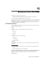
15.1Definition of Terms . . . . . . . . . . . . . . . . . . . . . . . . . . . . . . . . . . . . . . . . . . . . . . . . . . . . . . . . . . . . . . . . . 15-1
15.2Single-Sided and Double-Sided Media . . . . . . . . . . . . . . . . . . . . . . . . . . . . . . . . . . . . . . . . . . . . . . . . . . 15-3
15.3The RV02K Optical Cartridge . . . . . . . . . . . . . . . . . . . . . . . . . . . . . . . . . . . . . . . . . . . . . . . . . . . . . . . . . 15-3
15.4Volume States . . . . . . . . . . . . . . . . . . . . . . . . . . . . . . . . . . . . . . . . . . . . . . . . . . . . . . . . . . . . . . . . . . . . . . 15-3
15.4.1 Determining the State of a Volume . . . . . . . . . . . . . . . . . . . . . . . . . . . . . . . . . . . . . . . . . . . . . . . . . . 15-5
15.4.1.1
Determining the State of Deallocated Volumes . . . . . . . . . . . . . . . . . . . . . . . . . . . . . . . . . . . . . 15-5
15.4.1.2
Defining the Transition Time of Volumes . . . . . . . . . . . . . . . . . . . . . . . . . . . . . . . . . . . . . . . . . 15-6
15.4.2 Changing a Volume State . . . . . . . . . . . . . . . . . . . . . . . . . . . . . . . . . . . . . . . . . . . . . . . . . . . . . . . . . 15-6
15.5Adding Volumes to the MDMS Volume Database . . . . . . . . . . . . . . . . . . . . . . . . . . . . . . . . . . . . . . . . . 15-7
15.5.1 Adding Volumes from DCL . . . . . . . . . . . . . . . . . . . . . . . . . . . . . . . . . . . . . . . . . . . . . . . . . . . . . . . 15-7
15.5.2 Adding Volumes from Menus . . . . . . . . . . . . . . . . . . . . . . . . . . . . . . . . . . . . . . . . . . . . . . . . . . . . . . 15-7
15.5.3 Adding Double-Sided Volumes . . . . . . . . . . . . . . . . . . . . . . . . . . . . . . . . . . . . . . . . . . . . . . . . . . . . 15-8
15.6Initializing Volumes . . . . . . . . . . . . . . . . . . . . . . . . . . . . . . . . . . . . . . . . . . . . . . . . . . . . . . . . . . . . . . . . . 15-8
15.7Managing Volumes With MDMS . . . . . . . . . . . . . . . . . . . . . . . . . . . . . . . . . . . . . . . . . . . . . . . . . . . . . . 15-8
15.7.1 Assigning the Volume Default Location . . . . . . . . . . . . . . . . . . . . . . . . . . . . . . . . . . . . . . . . . . . . . . 15-8
15.7.2 Making Volumes Available . . . . . . . . . . . . . . . . . . . . . . . . . . . . . . . . . . . . . . . . . . . . . . . . . . . . . . . . 15-9
15.7.2.1
Defining the Default Volume Scratch Time for Allocation . . . . . . . . . . . . . . . . . . . . . . . . . . . . 15-9
15.7.2.2
Defining the Maximum User-Set Scratch Date . . . . . . . . . . . . . . . . . . . . . . . . . . . . . . . . . . . . . 15-9
15.7.2.3
Notifying Users of Scratch Date . . . . . . . . . . . . . . . . . . . . . . . . . . . . . . . . . . . . . . . . . . . . . . . 15-10
15.7.2.4
Enabling User Notification of Volume Scratch Date . . . . . . . . . . . . . . . . . . . . . . . . . . . . . . . . 15-10
15.7.2.5
Notifying Other Users When a Volume Reaches Its Scratch Date . . . . . . . . . . . . . . . . . . . . . 15-10
15.7.3 Reporting on Volume Usage . . . . . . . . . . . . . . . . . . . . . . . . . . . . . . . . . . . . . . . . . . . . . . . . . . . . . . 15-10
15.7.3.1
The Volume Usage Report . . . . . . . . . . . . . . . . . . . . . . . . . . . . . . . . . . . . . . . . . . . . . . . . . . . . 15-11
xi
15.7.3.2
Volume Accounting Period . . . . . . . . . . . . . . . . . . . . . . . . . . . . . . . . . . . . . . . . . . . . . . . . . . .
15.7.3.3
Customizing Your Volume Usage Report . . . . . . . . . . . . . . . . . . . . . . . . . . . . . . . . . . . . . . . .
15.7.3.4
Producing a Volume Usage Report on Demand . . . . . . . . . . . . . . . . . . . . . . . . . . . . . . . . . . .
15.8Printing Labels . . . . . . . . . . . . . . . . . . . . . . . . . . . . . . . . . . . . . . . . . . . . . . . . . . . . . . . . . . . . . . . . . . . .
15.8.1 Label Template Files . . . . . . . . . . . . . . . . . . . . . . . . . . . . . . . . . . . . . . . . . . . . . . . . . . . . . . . . . . . .
15.9When to Remove Volumes from the Database . . . . . . . . . . . . . . . . . . . . . . . . . . . . . . . . . . . . . . . . . . . .
15-11
15-11
15-12
15-13
15-13
15-13
16 Authorizing Access to MDMS Media
16.1Managing Volume Privileges . . . . . . . . . . . . . . . . . . . . . . . . . . . . . . . . . . . . . . . . . . . . . . . . . . . . . . . . . . 16-1
16.1.1 Default MDMS Privilege Assignments . . . . . . . . . . . . . . . . . . . . . . . . . . . . . . . . . . . . . . . . . . . . . . . 16-1
16.1.2 Privileges Required to Modify Volume Database Fields . . . . . . . . . . . . . . . . . . . . . . . . . . . . . . . . . 16-3
16.2Enabling Access to the MDMS Volume Database . . . . . . . . . . . . . . . . . . . . . . . . . . . . . . . . . . . . . . . . . . 16-3
16.2.1 MDMS Volume Database Access Authorization Screen . . . . . . . . . . . . . . . . . . . . . . . . . . . . . . . . . 16-4
16.2.2 Database Access Authorization Screen Fields . . . . . . . . . . . . . . . . . . . . . . . . . . . . . . . . . . . . . . . . . 16-4
16.2.3 How to Authorize MDMS Client Node Access to the MDMS Volume Database . . . . . . . . . . . . . . 16-4
16.2.4 How to Find a Node Name in the Database Access Authorization screen . . . . . . . . . . . . . . . . . . . . 16-5
16.2.5 How to Edit a Node Name in the Database Access Authorization Screen . . . . . . . . . . . . . . . . . . . . 16-6
16.2.6 How to Delete a Node Name in the Database Access Authorization Screen . . . . . . . . . . . . . . . . . . 16-6
16.3Authorizing Access to Volume Pools . . . . . . . . . . . . . . . . . . . . . . . . . . . . . . . . . . . . . . . . . . . . . . . . . . . . 16-7
16.3.1 MDMS Volume Pool Authorization Screen . . . . . . . . . . . . . . . . . . . . . . . . . . . . . . . . . . . . . . . . . . . 16-7
16.3.2 16.3.2 Volume Pool Authorization Screen Fields . . . . . . . . . . . . . . . . . . . . . . . . . . . . . . . . . . . . . . . 16-8
16.3.3 How to Authorize Access to Volume Pools . . . . . . . . . . . . . . . . . . . . . . . . . . . . . . . . . . . . . . . . . . . 16-8
16.3.4 How to Find a User Entry in the Volume Pool Authorization Screen . . . . . . . . . . . . . . . . . . . . . . . 16-9
16.3.5 How to Edit a User Entry in the Volume Pool Authorization Screen . . . . . . . . . . . . . . . . . . . . . . . 16-10
16.3.6 How to Delete a User Entry in the Volume Pool Authorization Screen . . . . . . . . . . . . . . . . . . . . . 16-10
17 Managing Vault Storage Using MDMS
17.1Vault Management Concepts . . . . . . . . . . . . . . . . . . . . . . . . . . . . . . . . . . . . . . . . . . . . . . . . . . . . . . . . . .
17.2Scheduling Vault Transfers with MDMS Software . . . . . . . . . . . . . . . . . . . . . . . . . . . . . . . . . . . . . . . . .
17.2.1 Scheduling Vault Dates . . . . . . . . . . . . . . . . . . . . . . . . . . . . . . . . . . . . . . . . . . . . . . . . . . . . . . . . . . .
17.2.1.1
Explicit Schedule . . . . . . . . . . . . . . . . . . . . . . . . . . . . . . . . . . . . . . . . . . . . . . . . . . . . . . . . . . . .
17.2.1.2
Daily or Weekly Schedule . . . . . . . . . . . . . . . . . . . . . . . . . . . . . . . . . . . . . . . . . . . . . . . . . . . . .
17.3Updating A Volume's On-Site or Off-Site Location . . . . . . . . . . . . . . . . . . . . . . . . . . . . . . . . . . . . . . . .
17.3.1 Changing Volume Locations Using RACK and VAULT . . . . . . . . . . . . . . . . . . . . . . . . . . . . . . . . .
17.3.2 Changing Volume Locations Using the Vault Management Menu . . . . . . . . . . . . . . . . . . . . . . . . .
17.3.3 Vault Management Menu Screen . . . . . . . . . . . . . . . . . . . . . . . . . . . . . . . . . . . . . . . . . . . . . . . . . . .
17.3.4 Vault Management Menu Options . . . . . . . . . . . . . . . . . . . . . . . . . . . . . . . . . . . . . . . . . . . . . . . . . .
17.3.4.1
Vault Management Menu: Change to On-site . . . . . . . . . . . . . . . . . . . . . . . . . . . . . . . . . . . . . .
17.3.4.2
Vault Management Menu: Change to Off-site . . . . . . . . . . . . . . . . . . . . . . . . . . . . . . . . . . . . . .
17.3.4.3
Vault Management Menu: Mass Movement . . . . . . . . . . . . . . . . . . . . . . . . . . . . . . . . . . . . . . .
17.3.4.4
Vault Management Menu: Change On-site Date . . . . . . . . . . . . . . . . . . . . . . . . . . . . . . . . . . . .
17.3.4.5
Vault Management Menu: Change Off-site Date . . . . . . . . . . . . . . . . . . . . . . . . . . . . . . . . . . .
17.3.4.6
Vault Management Menu: Change Name for Current Process . . . . . . . . . . . . . . . . . . . . . . . . .
17.4Generating Reports . . . . . . . . . . . . . . . . . . . . . . . . . . . . . . . . . . . . . . . . . . . . . . . . . . . . . . . . . . . . . . . . . .
17-1
17-2
17-2
17-2
17-3
17-5
17-5
17-6
17-6
17-6
17-7
17-7
17-8
17-8
17-9
17-9
17-9
18 Configuring New Devices
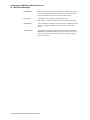
18.1Overview . . . . . . . . . . . . . . . . . . . . . . . . . . . . . . . . . . . . . . . . . . . . . . . . . . . . . . . . . . . . . . . . . . . . . . . . . . 18-1
18.1.1 Configuring . . . . . . . . . . . . . . . . . . . . . . . . . . . . . . . . . . . . . . . . . . . . . . . . . . . . . . . . . . . . . . . . . . . . 18-1
C TAPESTART.COM Quick Reference
xii
C.1 TAPESTART.COM Symbols for Configuration . . . . . . . . . . . . . . . . . . . . . . . . . . . . . . . . . . . . . . . . . . . . C-1
C.2 TAPESTART.COM Symbols for Standby Archiving . . . . . . . . . . . . . . . . . . . . . . . . . . . . . . . . . . . . . . . . C-3
C.3 TAPESTART.COM Symbols for Restore Operations . . . . . . . . . . . . . . . . . . . . . . . . . . . . . . . . . . . . . . . . C-4
xiii
xiv
Tables
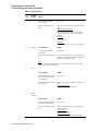
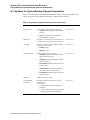
Table 2–1Operator Menu Options . . . . . . . . . . . . . . . . . . . . . . . . . . . . . . . . . . . . . . . . . . . . . . . . . . . . . . . . . . . 2-3
Table 2–2User Menu Options . . . . . . . . . . . . . . . . . . . . . . . . . . . . . . . . . . . . . . . . . . . . . . . . . . . . . . . . . . . . . . 2-5
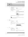
Table 3–1Establishing the Active Server Node . . . . . . . . . . . . . . . . . . . . . . . . . . . . . . . . . . . . . . . . . . . . . . . . . 3-3
Table 3–2Establishing a Client Connection on a OpenVMS Cluster . . . . . . . . . . . . . . . . . . . . . . . . . . . . . . . . 3-4
Table 3–3How to Optimize a SLS Data File . . . . . . . . . . . . . . . . . . . . . . . . . . . . . . . . . . . . . . . . . . . . . . . . . . 3-11
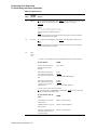
Table 4–1Values for SEPARATE_VERSION . . . . . . . . . . . . . . . . . . . . . . . . . . . . . . . . . . . . . . . . . . . . . . . . . 4-5
Table 4–2How to Change Pointer Values . . . . . . . . . . . . . . . . . . . . . . . . . . . . . . . . . . . . . . . . . . . . . . . . . . . . . 4-7
Table 4–3Values for NULL_NODE . . . . . . . . . . . . . . . . . . . . . . . . . . . . . . . . . . . . . . . . . . . . . . . . . . . . . . . . . 4-8
Table 4–4Transferring Existing Backup Files if no Listing Available . . . . . . . . . . . . . . . . . . . . . . . . . . . . . . . 4-8
Table 4–5Values for SLS$USRBAK Logical . . . . . . . . . . . . . . . . . . . . . . . . . . . . . . . . . . . . . . . . . . . . . . . . . 4-10
Table 4–6Accessing the SYSCLN Menu . . . . . . . . . . . . . . . . . . . . . . . . . . . . . . . . . . . . . . . . . . . . . . . . . . . . 4-13
Table 4–7SYSCLN Menu Options Descriptions . . . . . . . . . . . . . . . . . . . . . . . . . . . . . . . . . . . . . . . . . . . . . . . 4-13
Table 4–8Start SYSCLN Processing . . . . . . . . . . . . . . . . . . . . . . . . . . . . . . . . . . . . . . . . . . . . . . . . . . . . . . . . 4-15
Table 4–9Shutdown SYSCLN Processing . . . . . . . . . . . . . . . . . . . . . . . . . . . . . . . . . . . . . . . . . . . . . . . . . . . 4-16
Table 4–10Inquire SYSCLN status . . . . . . . . . . . . . . . . . . . . . . . . . . . . . . . . . . . . . . . . . . . . . . . . . . . . . . . . . 4-16
Table 4–11Abort SYSCLN Process . . . . . . . . . . . . . . . . . . . . . . . . . . . . . . . . . . . . . . . . . . . . . . . . . . . . . . . . 4-18
Table 4–12Delete User Histories . . . . . . . . . . . . . . . . . . . . . . . . . . . . . . . . . . . . . . . . . . . . . . . . . . . . . . . . . . . 4-19
Table 4–13How to Restore the Volume or Magazine Database from a BACKUP Copy . . . . . . . . . . . . . . . . 4-20
Table 4–14How to Restore the SLS System History Files from a BACKUP Copy . . . . . . . . . . . . . . . . . . . . 4-21
Table 4–15How to Manually Update SLS System History Files . . . . . . . . . . . . . . . . . . . . . . . . . . . . . . . . . . 4-22
Table 4–16How to Implement a Data Safety Policy Using the VMS Backup Utility with VAX RMS Journaling
4-23
Table 4–17How to Respond to a VAX RMS Journal Device Failure . . . . . . . . . . . . . . . . . . . . . . . . . . . . . . . 4-24
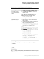
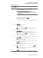
Table 5–1How to specify the days to run system backup operations . . . . . . . . . . . . . . . . . . . . . . . . . . . . . . . 5-12
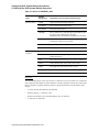
Table 5–2Execution Sequence for Pre- and Post-Processing Symbols . . . . . . . . . . . . . . . . . . . . . . . . . . . . . . 5-16
Table 5–3Symbols Enabled for Pre- and Post-Processing . . . . . . . . . . . . . . . . . . . . . . . . . . . . . . . . . . . . . . . . 5-17
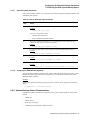
Table 5–4When to use QUALIFIERS or QUALIFIERS_n . . . . . . . . . . . . . . . . . . . . . . . . . . . . . . . . . . . . . . 5-20
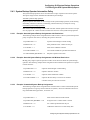
Table 5–5When to use OUTPUT_QUAL or OUTPUT_QUAL_n . . . . . . . . . . . . . . . . . . . . . . . . . . . . . . . . . 5-21
Table 5–6Recommended QUALIFIERS or QUALIFIERS_n Assignments . . . . . . . . . . . . . . . . . . . . . . . . . . 5-22
Table 5–7Mount Action Symbol Assignments . . . . . . . . . . . . . . . . . . . . . . . . . . . . . . . . . . . . . . . . . . . . . . . . 5-25
Table 5–8Values for SAVESET_GEN . . . . . . . . . . . . . . . . . . . . . . . . . . . . . . . . . . . . . . . . . . . . . . . . . . . . . . 5-26
Table 5–9How to Generate Save Set Names . . . . . . . . . . . . . . . . . . . . . . . . . . . . . . . . . . . . . . . . . . . . . . . . . . 5-27
Table 5–10Values for AUTOSEL . . . . . . . . . . . . . . . . . . . . . . . . . . . . . . . . . . . . . . . . . . . . . . . . . . . . . . . . . . 5-31
Table 5–11How to Handle System Backup Volumes . . . . . . . . . . . . . . . . . . . . . . . . . . . . . . . . . . . . . . . . . . . 5-31
Table 5–12Values for CONTLOADOPT . . . . . . . . . . . . . . . . . . . . . . . . . . . . . . . . . . . . . . . . . . . . . . . . . . . . 5-32
Table 5–13Values for OFFSITE DATE and ONSITE DATE . . . . . . . . . . . . . . . . . . . . . . . . . . . . . . . . . . . . 5-35
Table 5–14Values for TAPE LABELS . . . . . . . . . . . . . . . . . . . . . . . . . . . . . . . . . . . . . . . . . . . . . . . . . . . . . . 5-36
Table 5–15Values for DRIVE TYPE . . . . . . . . . . . . . . . . . . . . . . . . . . . . . . . . . . . . . . . . . . . . . . . . . . . . . . . 5-36
Table 5–16SLS Implementation of N_DRIVES Symbol . . . . . . . . . . . . . . . . . . . . . . . . . . . . . . . . . . . . . . . . 5-37
Table 5–17Values for PROGRESS Symbol . . . . . . . . . . . . . . . . . . . . . . . . . . . . . . . . . . . . . . . . . . . . . . . . . . 5-38
Table 5–18Values for SUMMARY FILE . . . . . . . . . . . . . . . . . . . . . . . . . . . . . . . . . . . . . . . . . . . . . . . . . . . . 5-41
Table 6–1Setting Save Screen Defaults using BAKOPT . . . . . . . . . . . . . . . . . . . . . . . . . . . . . . . . . . . . . . . . . 6-3
Table 6–2Values for BACKUP_DEFAULT_REEL . . . . . . . . . . . . . . . . . . . . . . . . . . . . . . . . . . . . . . . . . . . . . 6-4
Table 6–3How to define the Hexadecimal Protection Code . . . . . . . . . . . . . . . . . . . . . . . . . . . . . . . . . . . . . . . 6-4
Table 6–4Manual System Backup Procedure . . . . . . . . . . . . . . . . . . . . . . . . . . . . . . . . . . . . . . . . . . . . . . . . . . 6-8
Table 6–5Keys Defined for User Save Operations . . . . . . . . . . . . . . . . . . . . . . . . . . . . . . . . . . . . . . . . . . . . . 6-18
Table 6–6Save Screen . . . . . . . . . . . . . . . . . . . . . . . . . . . . . . . . . . . . . . . . . . . . . . . . . . . . . . . . . . . . . . . . . . . 6-20
Table 6–7How Unattended Backup Operations Work . . . . . . . . . . . . . . . . . . . . . . . . . . . . . . . . . . . . . . . . . . 6-27
Table 6–8Performing an Unattended System Backup Operation . . . . . . . . . . . . . . . . . . . . . . . . . . . . . . . . . . 6-29
Table 6–9Unattended System Backups Using Preallocated VolumeSets . . . . . . . . . . . . . . . . . . . . . . . . . . . . 6-30
Table 7–1Values for RESOPT . . . . . . . . . . . . . . . . . . . . . . . . . . . . . . . . . . . . . . . . . . . . . . . . . . . . . . . . . . . . . . 7-2
xv
Table 7–2Full Disk Restore . . . . . . . . . . . . . . . . . . . . . . . . . . . . . . . . . . . . . . . . . . . . . . . . . . . . . . . . . . . . . . . . 7-3
Table 7–3Ways to Restore a File or Group of Files . . . . . . . . . . . . . . . . . . . . . . . . . . . . . . . . . . . . . . . . . . . . . 7-6
Table 7–4Defined Keys for Restore Screen . . . . . . . . . . . . . . . . . . . . . . . . . . . . . . . . . . . . . . . . . . . . . . . . . . . . 7-7
Table 7–5Restore Screen . . . . . . . . . . . . . . . . . . . . . . . . . . . . . . . . . . . . . . . . . . . . . . . . . . . . . . . . . . . . . . . . . . 7-7
Table 8–1Process for Defining Database System Backup Operations . . . . . . . . . . . . . . . . . . . . . . . . . . . . . . . 8-3
Table 8–2Symbols with New Meanings . . . . . . . . . . . . . . . . . . . . . . . . . . . . . . . . . . . . . . . . . . . . . . . . . . . . . . 8-5
Table 8–3Process for Restoring a Database . . . . . . . . . . . . . . . . . . . . . . . . . . . . . . . . . . . . . . . . . . . . . . . . . . . 8-9
Table 9–1Preparing for Automatic Archiving . . . . . . . . . . . . . . . . . . . . . . . . . . . . . . . . . . . . . . . . . . . . . . . . . . 9-1
Table 9–2Automatic Archiving Symbols in ARCHIVE_SBK.COM . . . . . . . . . . . . . . . . . . . . . . . . . . . . . . . . 9-4
Table 9–3The Standby Archiving Process . . . . . . . . . . . . . . . . . . . . . . . . . . . . . . . . . . . . . . . . . . . . . . . . . . . . . 9-7
Table 9–4How to Access the Standby Archive Menu . . . . . . . . . . . . . . . . . . . . . . . . . . . . . . . . . . . . . . . . . . . 9-10
Table 9–5Options for Standby Archive Menu . . . . . . . . . . . . . . . . . . . . . . . . . . . . . . . . . . . . . . . . . . . . . . . . . 9-11
Table 9–6Start Up Standby Archive . . . . . . . . . . . . . . . . . . . . . . . . . . . . . . . . . . . . . . . . . . . . . . . . . . . . . . . . 9-12
Table 9–7Shutdown Standby Archive . . . . . . . . . . . . . . . . . . . . . . . . . . . . . . . . . . . . . . . . . . . . . . . . . . . . . . . 9-15
Table 9–8Inquire Pending Jobs . . . . . . . . . . . . . . . . . . . . . . . . . . . . . . . . . . . . . . . . . . . . . . . . . . . . . . . . . . . . 9-16
Table 9–9Abort Standby Archive . . . . . . . . . . . . . . . . . . . . . . . . . . . . . . . . . . . . . . . . . . . . . . . . . . . . . . . . . . 9-17
Table 9–10How to Authorize Class Access for a User . . . . . . . . . . . . . . . . . . . . . . . . . . . . . . . . . . . . . . . . . . 9-19
Table 9–11Creating a User Save Request For Standby Archiving . . . . . . . . . . . . . . . . . . . . . . . . . . . . . . . . . 9-21
Table 10–1Inquire Pending Jobs . . . . . . . . . . . . . . . . . . . . . . . . . . . . . . . . . . . . . . . . . . . . . . . . . . . . . . . . . . . 10-1
Table 10–2Report of Files on User Backups . . . . . . . . . . . . . . . . . . . . . . . . . . . . . . . . . . . . . . . . . . . . . . . . . . 10-2
Table 10–3Report of Files on System Backups . . . . . . . . . . . . . . . . . . . . . . . . . . . . . . . . . . . . . . . . . . . . . . . . 10-3
Table 11–1MDMS Databases and Their Contents . . . . . . . . . . . . . . . . . . . . . . . . . . . . . . . . . . . . . . . . . . . . . 11-2
Table 12–1Creating Default Media Triplets . . . . . . . . . . . . . . . . . . . . . . . . . . . . . . . . . . . . . . . . . . . . . . . . . . 12-6
Table 12–2Inserting Media Triplets into TAPESTART.COM . . . . . . . . . . . . . . . . . . . . . . . . . . . . . . . . . . . . 12-6
Table 13–1Determining Your Hardware Configuation . . . . . . . . . . . . . . . . . . . . . . . . . . . . . . . . . . . . . . . . . . 13-4
Table 13–2Creating A Tape Robot Unit . . . . . . . . . . . . . . . . . . . . . . . . . . . . . . . . . . . . . . . . . . . . . . . . . . . . . 13-5
Table 13–3Using a SCSI Loader on an HSC Controller . . . . . . . . . . . . . . . . . . . . . . . . . . . . . . . . . . . . . . . . . 13-7
Table 13–4Using a SCSI Loader on an HSD or HSJ Controller . . . . . . . . . . . . . . . . . . . . . . . . . . . . . . . . . . . 13-7
Table 13–5Using a TL810/820 SCSI Device Connected to an HSD or HSJ . . . . . . . . . . . . . . . . . . . . . . . . . 13-8
Table 13–6Process for Using Magazines with Tape Jukeboxes . . . . . . . . . . . . . . . . . . . . . . . . . . . . . . . . . . 13-13
Table 13–7How to Manually Bind Volumes to a Magazine . . . . . . . . . . . . . . . . . . . . . . . . . . . . . . . . . . . . . 13-14
Table 13–8Calculating Slot Numbers . . . . . . . . . . . . . . . . . . . . . . . . . . . . . . . . . . . . . . . . . . . . . . . . . . . . . . 13-17
Table 13–9Using Uncataloged Media with a TL800 Class Jukebox . . . . . . . . . . . . . . . . . . . . . . . . . . . . . . . 13-24
Table 13–10Using Cataloged Media with a TL800 Class Jukebox . . . . . . . . . . . . . . . . . . . . . . . . . . . . . . . . 13-25
Table 13–11Inventorying Volume Series . . . . . . . . . . . . . . . . . . . . . . . . . . . . . . . . . . . . . . . . . . . . . . . . . . . 13-30
Table 13–12Importing Volumes . . . . . . . . . . . . . . . . . . . . . . . . . . . . . . . . . . . . . . . . . . . . . . . . . . . . . . . . . . 13-32
Table 13–13Initializing Volume Series . . . . . . . . . . . . . . . . . . . . . . . . . . . . . . . . . . . . . . . . . . . . . . . . . . . . . 13-34
Table 13–14Loading Volumes Onto a Drive . . . . . . . . . . . . . . . . . . . . . . . . . . . . . . . . . . . . . . . . . . . . . . . . . 13-37
Table 13–15Unloading Drives . . . . . . . . . . . . . . . . . . . . . . . . . . . . . . . . . . . . . . . . . . . . . . . . . . . . . . . . . . . . 13-39
Table 13–16Unloading Volumes . . . . . . . . . . . . . . . . . . . . . . . . . . . . . . . . . . . . . . . . . . . . . . . . . . . . . . . . . . 13-40
Table 13–17Exporting Volumes . . . . . . . . . . . . . . . . . . . . . . . . . . . . . . . . . . . . . . . . . . . . . . . . . . . . . . . . . . 13-41
Table 14–1How to Change Network Parameters . . . . . . . . . . . . . . . . . . . . . . . . . . . . . . . . . . . . . . . . . . . . . 14-19
Table 15–1Volume States . . . . . . . . . . . . . . . . . . . . . . . . . . . . . . . . . . . . . . . . . . . . . . . . . . . . . . . . . . . . . . . . 15-4
Table 15–2Allowable Assignments for the FRESTA Symbol . . . . . . . . . . . . . . . . . . . . . . . . . . . . . . . . . . . . 15-5
Table 15–3How to Change the Volume State . . . . . . . . . . . . . . . . . . . . . . . . . . . . . . . . . . . . . . . . . . . . . . . . . 15-6
Table 15–4Customizing Your Volume Usage Report . . . . . . . . . . . . . . . . . . . . . . . . . . . . . . . . . . . . . . . . . . 15-11
Table 16–1Volume Management Privileges . . . . . . . . . . . . . . . . . . . . . . . . . . . . . . . . . . . . . . . . . . . . . . . . . . 16-2
Table 16–2How to Authorize Client Node Access to the MDMS Volume Database . . . . . . . . . . . . . . . . . . . 16-5
Table 16–3How to Find a Node Name in the Database Access Authorization Screen . . . . . . . . . . . . . . . . . . 16-5
Table 16–4How to Edit a Node Entry in the Database Access Authorization Screen . . . . . . . . . . . . . . . . . . 16-6
Table 16–5How to Delete a Node Name Entry in the Database Access Authorization Screen . . . . . . . . . . . 16-7
Table 16–6How to Enable User Access to Volume Pools . . . . . . . . . . . . . . . . . . . . . . . . . . . . . . . . . . . . . . . . 16-8
xvi
Table 16–7How to Find a User Entry in the Volume Pool Authorization Screen . . . . . . . . . . . . . . . . . . . . . . 16-9
Table 16–8How to Edit a User Entry in the Volume Pool Authorization Screen . . . . . . . . . . . . . . . . . . . . . 16-10
Table 16–9How to Delete a User Entry in the Volume Pool Authorization Screen . . . . . . . . . . . . . . . . . . . 16-11
Table 17–1How to Establish a Daily or Weekly Vault Schedule . . . . . . . . . . . . . . . . . . . . . . . . . . . . . . . . . . 17-3
Table 17–2Vault Management Menu Options . . . . . . . . . . . . . . . . . . . . . . . . . . . . . . . . . . . . . . . . . . . . . . . . . 17-7
xvii
xviii
Figures
Figure 2–1
Figure 2–2
Figure 2–3
Figure 3–1
Figure 3–2
Figure 3–3
Figure 3–4
Figure 4–1
Figure 4–2
Figure 4–3
Figure 4–4
Figure 6–1
Figure 6–2
Figure 7–1
Figure 7–2
Figure 9–1
Figure 9–2
Figure 9–3
Figure 9–4
Figure 9–5
Figure 9–6
Figure 13–1
Figure 13–2
Figure 13–3
Figure 13–4
Figure 13–5
Figure 13–6
Figure 13–7
Figure 13–8
Figure 13–9
Figure 14–1
Figure 14–2
Figure 14–3
Figure 14–4
Figure 14–5
Figure 15–1
Figure 16–1
Figure 16–2
Figure 17–1
SLS Administrator Menu . . . . . . . . . . . . . . . . . . . . . . . . . . . . . . . . . . . . . . . . . . . . . . . . . . . . . . . 2-2
Operator Menu . . . . . . . . . . . . . . . . . . . . . . . . . . . . . . . . . . . . . . . . . . . . . . . . . . . . . . . . . . . . . . . 2-3
User Menu . . . . . . . . . . . . . . . . . . . . . . . . . . . . . . . . . . . . . . . . . . . . . . . . . . . . . . . . . . . . . . . . . . . 2-5
SLS Server and Client Processes . . . . . . . . . . . . . . . . . . . . . . . . . . . . . . . . . . . . . . . . . . . . . . . . . 3-2
Two-Node SLS Client-Server Process . . . . . . . . . . . . . . . . . . . . . . . . . . . . . . . . . . . . . . . . . . . . . 3-5
Three-Node SLS Client-Server Process . . . . . . . . . . . . . . . . . . . . . . . . . . . . . . . . . . . . . . . . . . . . 3-6
Five-Node SLS Client-Server Process . . . . . . . . . . . . . . . . . . . . . . . . . . . . . . . . . . . . . . . . . . . . . 3-8
SYSCLN Menu . . . . . . . . . . . . . . . . . . . . . . . . . . . . . . . . . . . . . . . . . . . . . . . . . . . . . . . . . . . . . . 4-13
Start SYSCLN Processing Screen. . . . . . . . . . . . . . . . . . . . . . . . . . . . . . . . . . . . . . . . . . . . . . . . 4-14
Shutdown SYSCLN Processing screen. . . . . . . . . . . . . . . . . . . . . . . . . . . . . . . . . . . . . . . . . . . . 4-15
Delete User Histories Screen Diagram . . . . . . . . . . . . . . . . . . . . . . . . . . . . . . . . . . . . . . . . . . . . 4-19
Manual System Backup. . . . . . . . . . . . . . . . . . . . . . . . . . . . . . . . . . . . . . . . . . . . . . . . . . . . . . . . . 6-7
Save Screen . . . . . . . . . . . . . . . . . . . . . . . . . . . . . . . . . . . . . . . . . . . . . . . . . . . . . . . . . . . . . . . . . 6-19
Full Disk Restore Screen. . . . . . . . . . . . . . . . . . . . . . . . . . . . . . . . . . . . . . . . . . . . . . . . . . . . . . . . 7-3
Restore Screen. . . . . . . . . . . . . . . . . . . . . . . . . . . . . . . . . . . . . . . . . . . . . . . . . . . . . . . . . . . . . . . . 7-7
File Retention Times . . . . . . . . . . . . . . . . . . . . . . . . . . . . . . . . . . . . . . . . . . . . . . . . . . . . . . . . . . . 9-2
illustrates the Standby Archive Menu. . . . . . . . . . . . . . . . . . . . . . . . . . . . . . . . . . . . . . . . . . . . . 9-10
Standby Archive Menu.. . . . . . . . . . . . . . . . . . . . . . . . . . . . . . . . . . . . . . . . . . . . . . . . . . . . . . . . 9-12
Shutdown Standby Archive. . . . . . . . . . . . . . . . . . . . . . . . . . . . . . . . . . . . . . . . . . . . . . . . . . . . . 9-15
Inquire Pending Jobs . . . . . . . . . . . . . . . . . . . . . . . . . . . . . . . . . . . . . . . . . . . . . . . . . . . . . . . . . . 9-16
B1C.TEMPLATE . . . . . . . . . . . . . . . . . . . . . . . . . . . . . . . . . . . . . . . . . . . . . . . . . . . . . . . . . . . . 9-19
Determining a Magnetic Tape Jukebox Hardware Configuration . . . . . . . . . . . . . . . . . . . . . . . 13-3
ACS Management Menu . . . . . . . . . . . . . . . . . . . . . . . . . . . . . . . . . . . . . . . . . . . . . . . . . . . . . . 13-29
Inventory Volume Series. . . . . . . . . . . . . . . . . . . . . . . . . . . . . . . . . . . . . . . . . . . . . . . . . . . . . . 13-30
Import Volumes(s) Screen . . . . . . . . . . . . . . . . . . . . . . . . . . . . . . . . . . . . . . . . . . . . . . . . . . . . 13-32
Initialize Volume Series Screen . . . . . . . . . . . . . . . . . . . . . . . . . . . . . . . . . . . . . . . . . . . . . . . . 13-34
Load Volume Onto Drive Screen . . . . . . . . . . . . . . . . . . . . . . . . . . . . . . . . . . . . . . . . . . . . . . . 13-37
Unload Drive Screen . . . . . . . . . . . . . . . . . . . . . . . . . . . . . . . . . . . . . . . . . . . . . . . . . . . . . . . . . 13-39
Unload Volume(s) Screen . . . . . . . . . . . . . . . . . . . . . . . . . . . . . . . . . . . . . . . . . . . . . . . . . . . . . 13-40
Export Volume Screen . . . . . . . . . . . . . . . . . . . . . . . . . . . . . . . . . . . . . . . . . . . . . . . . . . . . . . . 13-41
How RDF and MDMS Software Communicate . . . . . . . . . . . . . . . . . . . . . . . . . . . . . . . . . . . . . 14-3
Single Remote Device . . . . . . . . . . . . . . . . . . . . . . . . . . . . . . . . . . . . . . . . . . . . . . . . . . . . . . . . . 14-5
Local Area Network . . . . . . . . . . . . . . . . . . . . . . . . . . . . . . . . . . . . . . . . . . . . . . . . . . . . . . . . . . 14-7
Two-Way Remote Backup Operation . . . . . . . . . . . . . . . . . . . . . . . . . . . . . . . . . . . . . . . . . . . . . 14-9
Backup Operation Among Multiple Remote Nodes . . . . . . . . . . . . . . . . . . . . . . . . . . . . . . . . . 14-12
Volume State Cycling . . . . . . . . . . . . . . . . . . . . . . . . . . . . . . . . . . . . . . . . . . . . . . . . . . . . . . . . . 15-4
Database Access Authorization. . . . . . . . . . . . . . . . . . . . . . . . . . . . . . . . . . . . . . . . . . . . . . . . . . 16-4
Volume Pool Authorization . . . . . . . . . . . . . . . . . . . . . . . . . . . . . . . . . . . . . . . . . . . . . . . . . . . . 16-8
Vault Management Menu . . . . . . . . . . . . . . . . . . . . . . . . . . . . . . . . . . . . . . . . . . . . . . . . . . . . . . 17-6
xix
xx
Preface
Purpose of This Document
This document contains information about Storage Library System for OpenVMS™ Version
2.9J software and its backup, archive, and restore functions. Use this document to define, configure, operate, and maintain your SLS environment.
Once SLS is installed on your system, the online release notes are available in:
SYS$HELP:SLSJ029.RELEASE_NOTES
Intended Audience
This manual is intended for users of SLS software, including storage administrators, operators,
and users.
Document Structure
This document is organized in the following manner and includes the following information:
Chapter 1
Introduces storage management and the key concepts of SLS.
Chapter 2
Introduces the SLS menu interface.
Chapter 3
Explains how to maintain the safety of SLS data.
Chapter 4
Describes how to configure SLS software for system backup operations.
Chapter 5
Explains how to save copies of data using SLS.
Chapter 6
Explains how to restore individual data files and disks using SLS.
Chapter 7
Describes how to save and restore Oracle Rdb databases through SLS.
Chapter 8
Explains how to use SLS to archive data.
Chapter 9
Describes how to generate SLS reports.
Chapter 10
Describes the command interface for SLS. This chapter serves as the SLS command reference guide for backup and restore commands. For information about
media and device management commands, see the Media and Device Management Services for OpenVMS Guide to Operations.
xxi
Appendix A Provides a list of TAPESTART.COM symbols.
Appendix B Lists system backup command file (*.SBK) symbols.
Appendix C Provides a worksheet for configuring and performing backups to and from remote
devices.
Related Documents
The following documents are related to this documentation set or are mentioned in this manual:
•
Media and Device Management Services for OpenVMS Guide to Operations
•
OpenVMS System Management Utilities Reference Manual: A--L
•
OpenVMS DCL Dictionary: A--M
•
OpenVMS DCL Dictionary: N--Z
•
OpenVMS License Management Utility Manual
•
OpenVMS User's Manual
•
Storage Library System for OpenVMS Installation Guide
Conventions
The following conventions are used in this document:
xxii
Convention
Description
{}
In format command descriptions, braces indicate required elements.
You must include one of the elements.
[]
Square brackets show optional elements in command syntax. You can omit these
elements if you wish to use the default response.
...
Horizontal ellipsis points indicate the omission of information from a sentence or
paragraph that is not important to the topic being discussed.
.
.
.
Vertical ellipsis points indicate the omission of information from an example or
command format. The information has been omitted because it is not important to
the topic being discussed.
boldface type
Boldface type in text indicates the first instance of a term defined in the Glossary or
defined in text.
italic type
Italic type emphasizes important information, indicates variables, indicates complete titles of manuals, and indicates parameters for system information.
Starting
test ...
This type font denotes system response, user input, and examples.
Ctrl/x
Hold down the key labeled Ctrl (Control) and the specified key simultaneously
(such as Ctrl/Z).
Convention
Description
PF1 x
The key sequence PF1 x instructs you to press and release the PF1 key, and then
press and release another key (indicated here by x).
n
A lowercase n denotes the generic use of a number. For example, 19nn indicates a
four-digit number in which the last two digits are unknown.
x
A lowercase x denotes the generic use of a letter. For example, xxx indicates any
combination of three alphabetic characters.
Related Products
The following related products are mentioned in this document:
Product
Description
ABS
ABS refers to Archive Backup System for OpenVMS™, Version 4.3 software.
HSM
HSM refers to Hierarchical Storage Management for OpenVMS, Version 4.3 software.
MDMS
MDMS refers to Media, Device and Management Services for OpenVMS, Version
2.9J software.
SMF
SMF refers to Sequential Media Filesystem for OpenVMS, Version 1.3 software.
SLS
SLS refers to Storage Library System for OpenVMS, Version 2.9J software.
Determining and Reporting Problems
If you encounter a problem while using SLS, report it to HP through your usual support channels.
Review the Software Product Description (SPD) and Warranty Addendum for an explanation of
warranty. If you encounter a problem during the warranty period, report the problem as indicated
above or follow alternate instructions provided by HP for reporting SPD nonconformance problems.
xxiii
Part I
SLS Application Guide
This part contains information about SMF operations including system backups, standby
archiving, and restoring data.
1
Introduction to Storage Library System
for OpenVMS
1.1 SLS Storage Management Concepts
Because your data represents a substantial investment, it is important to safeguard it. The tasks
of storage management are concerned with managing storage resources for data maintenance.
The following sections describe the fundamental concepts and principles of storage management
and how SLS software can help you implement them.
1.1.1 Why You Save Data
SLS software manages the movement of data from online data storage to nearline and offline
data storage.
Primary reasons:
There are two primary reasons for saving data:
1.
Data safety
2.
Business or statutory reasons
Secondary reason:
A secondary reason for saving data is to manage online storage space. To meet cost and resource
needs, data saved to nearline or offline storage can be deleted to make more storage space available.
1.1.1.1
Backup Copy of Data
The purpose of a backup copy is to be able to recover data after unexpected loss, including:
•
Equipment failure
•
Human error
•
Site catastrophe
Your data safety policy must accommodate disaster recovery. It is important to quickly retrieve
damaged or missing information to minimize your organization's down time.
Frequency of backup:
Backup copies typically occur in cycles. They are created periodically and lose importance after
some number of periods have passed.
Example:
An organization might make backup copies of user data every week and discard a saved copy
when it becomes five weeks old.
Introduction to Storage Library System for OpenVMS 1–1
Introduction to Storage Library System for OpenVMS
1.2 Storage Management Responsibilities
1.1.1.2
Archive Copy of Data
The purpose of an archive copy is business oriented. An archive copy is made to preserve data
to satisfy business requirements.
Frequency of archive:
Archive copies are typically created at the close of a business-related event or process. After the
archive copy is made, the original information may be deleted or retained for read-only access.
Archive copies are typically kept forever, unless they are explicitly deleted by the storage administrator.
Because archive copies are not frequently accessed, nearline or offline storage is suitable for
archived data.
Examples:
1.1.1.3
•
An organization might make archive copies of its yearly payroll account and retain them for
15 years to satisfy a government requirement.
•
An organization might make archive copies of inactive project data to make more online
storage space available.
•
A business may make an archive copy of software at each stage of development. The
archive copy is then removed to an off-site storage vault.
Defining Data Safety Policy
The storage administrator decides which data to move from online to nearline and offline storage. This decision needs to maximize resource efficiency without sacrificing the ability to
restore lost data.
To define the data safety policy, consider the following:
1.1.1.4
•
Which data has to be copied
•
The purpose for copying the data
•
How often and at what time the data is to be copied
•
The class of storage best suited for the data
•
The likelihood of its need
•
Operational staff support
Policy Implementation and Administration
SLS software allows you to implement decisions about saving and restoring data. The storage
administrator is responsible for reviewing and responding to the needs for saving and restoring
data as they change.
Ongoing policy administration includes responding to changes in:
•
The data to be saved
•
Computing available storage resources for the movement of data to nearline or offline storage
•
The personnel assigned to the media management tasks
1.2 Storage Management Responsibilities
There are three kinds of computer users that work with SLS:
Introduction to Storage Library System for OpenVMS 1-2
Introduction to Storage Library System for
OpenVMS
•
Storage administrators-responsible for designing and implementing storage management
policies
•
Operators-responsible for controlling media and devices to save and restore data
•
Users-responsible for managing their own data, which includes requesting information be
saved and restored
In any given operating environment, these kinds of users may not be distinguishable. However,
SLS provides menus and presumes particular responsibilities are appropriate for each. This section describes the responsibilities and SLS tasks for each of these users.
1.2.1 Storage Administrator's Responsibilities
The storage administrator's responsibilities include formulating and implementing an organization's storage management policy.
The storage administrator's responsibilities include:
•
Defining the data safety (backup and archiving) policy
•
Implementing and administering the policy
•
Installing SLS software
•
Configuring the SLS software
Storage Administrator's Tasks
The storage administrator's tasks include:
•
Installing the SLS software
•
Configuring the SLS software
•
Authorizing access to SLS features
•
Managing the use of media for backup and archive operations
•
Managing the accessibility and use of volumes
•
Managing the creation of backup copies
•
Managing the creation of archive copies
•
Managing data restore operations
1.2.2 Operator's Responsibilities
The operator is primarily concerned with implementing the storage management policy defined
by the storage administrator.
The operator's responsibilities include:
•
Following storage management policy to ensure the preservation of critical data
•
Managing media and devices needed by the SLS software to properly preserve data
•
Assisting SLS software users with save, archive and restore requests
Operator's Tasks
The operator's tasks include:
•
Initiating and responding to system and user save and restore operations
•
Initiating archiving operations
•
Restoring saved and/or archived copies of data
Introduction to Storage Library System for OpenVMS 1–3
Introduction to Storage Library System for OpenVMS
1.2 Storage Management Responsibilities
•
Managing the volume database
•
Managing the magazine database
•
Managing a volume's life cycle within the volume database
•
Managing media
•
Managing drives
•
Implementing on-site/off-site volume transfers
1.2.3 User's Responsibilities
The user's responsibilities include:
•
Managing their files, volumes and volume sets
•
Managing the selection and personal use of drives for their data storage
•
Performing save and restore operations of their data
•
Maintaining their part of the site-specific SLS software policy that the storage administrator
implemented (See your storage administrator for your site's policy.)
User's Tasks
The user's tasks include:
•
Choosing volumes
•
Arranging volumes and volume sets
•
Displaying information
•
Modifying volume attributes
•
Generating labels
•
Requesting reports
•
Choosing drives
•
Submitting user requests for save and restore operations
Introduction to Storage Library System for OpenVMS 1-4
2
Using SLS Menu Interfaces
SLS provides two ways for you to manage save and restore operations:
•
DCL STORAGE commands
•
SLS menu interface
This chapter introduces the menu interfaces for managing save and restore operations. These
menus also provide MDMS media and device management capabilities. Detailed information
about how to perform specific menu-driven tasks are provided in later sections of this book and
in the Media and Device Management Services for OpenVMS Guide to Operations.
For more information about the DCL STORAGE commands, see Storage Library System for
OpenVMS Command Reference Guide and the DCL STORAGE commands chapter in the Media
and Device Management Services for OpenVMS Guide to Operations.
2.1 SLS Menus
SLS provides three menus by which you can control the operation of the software:
•
Administrator Menu-Allows you to control volume pools and database authorization.
•
Operator Menu-Allows you to add and remove volumes, initiate backup and restore operations, and perform other volume maintenance tasks.
•
User Menu-Allows you to view information about volumes and perform user-controlled
backup operations.
Note
To make the SLS menus accessible, execute the following command file:$
@SYS$MANAGER:SLS$TAPSYMBOL.COM
2.2 Administrator Menu
The Administrator Menu accesses the functions that control the following two functions:
3.
Client node access to the volume database
4.
User access to volume pools
These are the only two functions available from this menu. There are no equivalent DCL STORAGE commands.
2.2.1 Accessing the Administrator Menu
Enter the following command to invoke the Administrator menu:
$ SLSMGR
Required Privilege:
Using SLS Menu Interfaces 2–1
Using SLS Menu Interfaces
2.3 Operator Menu
To access the Administrator Menu, you must have the OPER privilege.
2.2.2 Administrator Menu Diagram
Figure 2–1 shows SLS Administrator Menu
Figure 2–1 SLS Administrator Menu
2.2.3 Administrator Menu Options
The Administrator Menu for SLS is the same as for MDMS. For a description of the Administrator Menu and information on using this menu to authorize database and volume pool access, see
the Media and Device Management Services for OpenVMS Guide to Operations, Chapter 2.
2.3 Operator Menu
The Operator Menu provides access to various functions from a menu. All the functions available through the Operator Menu are also available through the STORAGE commands.
2.3.1 Accessing the Operator Menu
To access the Operator Menu, enter the following command at the DCL prompt:
$ SLSOPER
Required privilege:
To access the Operator Menu, you must have the OPER privilege.
2.3.2 Operator Menu Diagram
Figure 2–2 shows the Operator Menu.
Using SLS Menu Interfaces 2-2
Using SLS Menu Interfaces
2.3 Operator Menu
Figure 2–2 Operator Menu
2.3.3 Operator Menu Options
Table 2–1 describes the options on the Operator Menu.
Table 2–1 Operator Menu Options
Option
Description
1. Manual System
Backup
Through a series of questions, defines the parameters for a manual system
backup; this information can be stored in a .COM file for later execution. For
more information about performing manual system backups, see Section 6.2.
2. Save Screen
Provides a screen for defining parameters for a user save operation; this same
screen is accessible from the User menu. For more information about performing user save operations, see Section 6.3.
3. Full Disk Restore
Through a series of questions, supplies the requirements to restore an entire
disk. For more information about restoring a disk, see Section 7.2.
4. Restore Screen
Provides a screen for defining parameters for restoring files or groups of
files; this same screen is accessible from the User menu. For more information about restoring files, see Section 7.3.
5. Release Volumes
Asks for a volume name and changes the volume's state from transition to
free.
6. Update Clean Data
Sets the mount and error count fields to zero (0) for the specified volumes.
7. Initialize Volumes
Initializes specified volumes.
8. DCL Storage Command
Provides a DCL prompt at which you can enter any STORAGE command.
Press RETURN from the DCL prompt to return to the Operator Menu.
9. Delete User Histories
Deletes user history files for a specified user or for all users before a specified date.
Using SLS Menu Interfaces 2–3
Using SLS Menu Interfaces
2.4 User Menu
Table 2–1 Operator Menu Options
Option
Description
10. Tapejuke Initialize
Volume Series
Initializes a series of volumes contained in a jukebox. For more information
about working with tape jukeboxes, see the Media and Device Management
Services for OpenVMS Guide to Operations.
11. Maintenance
Brings up the Maintenance menu. For additional information, see the Media
and Device Management Services for OpenVMS Guide to Operations.
12. Vault Management
Brings up the Vault Management menu which allows you to access information about when volumes go to vaults and return. For additional information,
see the Media and Device Management Services for OpenVMS Guide to
Operations.
13. Standby Archive
Controls standby archiving operations.
14. SYSCLN
Controls the SYSCLN program, which deletes old SLS history file records
from each history set on the system.
15. ACS Management
Provides commands to work with volumes contained in a StorageTek ACS
4400 or StorageTek WolfCreek silo. For additional information about working with ACS silos, see Media and Device Management Services for OpenVMS Guide to Operations.
16. Free Volumes
Searches the volume database and creates a listing of all volumes whose state
is FREE.
17. Allocated Volumes
Searches the volume database and creates a listing of all volumes whose state
is ALLOCATED.
18. Down Volumes
Searches the volume database and creates a listing of all volumes whose state
is DOWN.
19. Volumes in Transition
Searches the volume database and creates a listing of all volumes whose state
is TRANSITION.
20. Volumes Due for
Allocation
Searches the volume database and creates a listing of all volumes in sequential order for allocation.
21. Volumes Due for
Cleaning
Searches the volume database and creates a listing of all volumes ready for
cleaning.
22. Quantity Control
Searches the volume database and creates a volume usage report.
2.4 User Menu
The User Menu allows you to control user-initiated save and restore requests and provides various ways of viewing information about SLS-managed media.
2.4.1 Accessing the User Menu
To access the User Menu, enter the following command at the DCL prompt:
$ SLSUSER
2.4.2 User Menu Diagram
Figure 2–3 shows the User Menu
Using SLS Menu Interfaces 2-4
Using SLS Menu Interfaces
2.4 User Menu
Figure 2–3 User Menu
2.4.3 User Menu Options
Table 2–2 describes the options available on the User Menu.
Table 2–2 User Menu Options
Option
Description
1. Save Screen
Provides a screen for defining parameters for a user save operation; this
same screen is accessible from the Operator menu. For more information
about performing user save operations, see Section 6.3.
2. Restore Screen
Provides a screen for defining parameters for restoring files or groups of
files; this same screen is accessible from the Operator menu. For more
information about restoring files, see Section 7.3.
3. Show Volume
Displays information about the specified volume.
4. Deallocate Volume
Deallocates the specified volume.
5. Modify Scratch Date
Changes the date for the volume to return to the scratch pool.
6. Modify Volume Note
Changes information about the volume contained in the note.
7. DCL Storage Command
Provides a DCL prompt at which you can enter any STORAGE command.
Press RETURN from the DCL prompt to return to the User Menu.
8. All Owned Volumes
Searches the volume database and creates a listing of all volumes owned
by this user.
9. Volumes by Scratch
Date
Searches the volume database and creates a listing of volumes and their
scratch dates.
Using SLS Menu Interfaces 2–5
Table 2–2 User Menu Options
Option
Description
10. Files on User Backups
Searches user history files to generate a listing of user backup operations
on a specified file or set of files.
11. Files on System Backups
Searches system history files to generate a listing of system backup operations on a specified file or set of files.
3
SLS Processes and Database Management
This chapter defines the client and server processes and describes their interoperability. This
chapter also discusses the feature for tuning interprocess communication, and the management
of the SLS database.
3.1 The SLS Server and Client Processes
SLS client and server processes ensure the volume and magazine databases are available when a
data request is made. The software implements the server and client processes. These processes
enable you to partition your work.
Server process:
The SLS server process is executed on a node where you set policy for storage management and
maintain information of files, media, and volumes.
Client process:
The SLS client process is executed on a node where you create replicated files.
3.1.1 Client and Server Definitions
This section defines SLS’s concepts of server and client. It is important that you understand what
each provides for SLS functionality.
3.1.1.1 Server Software
SLS server software gives users access to the full functionality of SLS software. SLS provides
this access at the node or OpenVMScluster system where the SLS software is executing.
SLS server software manages the:
•
Media database—A set of RMS files that describe all removable storage media known to
SLS software. These files are part of the Media and Device Management Services for OpenVMS (MDMS) portion of the SLS product. For detailed information about the MDMS databases, see the Media and Device Management Services for OpenVMS Guide to Operations.
A node or OpenVMScluster system executing SLS server software provides media management services both for itself and for any client nodes connected to it. The media database
contains information about volume names, locations, magazines, tape jukeboxes, and pool
access authorization.
•
SLS history files—Information is recorded at the local node about user files backed up or
archived under SLS control.
3.1.1.2 Client Software
SLS client software:
SLS Processes and Database Management 3–1
SLS Processes and Database Management
3.1 The SLS Server and Client Processes
•
Provides backup scheduling and archiving services for the node or OpenVMScluster system
on which it is executing
•
Acts as a client of another node executing SLS server software when it requires media management services
•
Provides users with full functionality when a node or OpenVMScluster system executing
SLS client software is communicating with another node or OpenVMScluster system executing SLS server software
Similar to the SLS server software, SLS client software also maintains historyfiles in which it
records information about user files backed up or archived locally under its control.
The node executing SLS client software communicates using DECnet software to a server node
running SLS server software. The server node maintains the media database.
3.1.2 Basic Block Diagram of SLS Server and Client Processes
This diagram shows the SLS server and client processes in a two-node configuration.
Figure 3–1 SLS Server and Client Processes
1 The SLS client node. This node runs the client process only. At this node, data is cop-
ied to the local device for safekeeping and statutory requirements.
2 The SLS server node. This node executes both the SLS server and client processes.
At this node, the SLS server process maintains the volume and magazine databases.
3 The volume and magazine databases. These databases maintain records of media
used for operations at both the server and client nodes.
SLS Processes and Database Management 3-2
SLS Processes and Database Management
3.2 The SLS Server Process in a OpenVMS
3.2 The SLS Server Process in a OpenVMS Cluster System
When the SLS server software is installed on a OpenVMS Cluster system, the SLS server process can be active on only one node at any time. The active server process is responsible for all
requests issued by any SLS client processes, whether from within our outside the OpenVMS
Cluster system.
A standby server process is any SLS server process in the OpenVMS Cluster system other than
the one currently processing requests from an SLS client process. A standby server process waits
and becomes active if the active server process fails.
3.2.1 Establishing the Active Server Node
Table 3–1describes how the SLS server process remains active on at least one node in a OpenVMS Cluster system.
Table 3–1 Establishing the Active Server Node
Table 3–1 Establishing the Active Server Node
Stage
Action
1.
As part of configuring SLS, you must identify the OpenVMS Cluster system nodes
that are eligible to become the SLS server process.
2.
During startup, SLS uses the OpenVMS Distributed Lock Manager to select one of
the nodes that you have identified as eligible to become a server node.
3.
The active server process:
• Is granted a lock to ensure it is the only active server process with direct access to the
SLS databases.
•
Establishes itself as the named network object to accept requests from SLS client processes
Note:
As long as the active server process exists, it holds the lock in a restricted access mode.
4.
The remaining OpenVMS Cluster system nodes executing the SLS server processes
become standby SLS servers.
5.
The standby sever process on each node enqueues a request for the lock held by
the active server node and waits for a response. If the active SLS server process fails, the
VMS Distributed Lock Manager grants the lock to the subsequent SLS
server process in the queue.
Note:
When necessary, this process repeats itself from Stage 3.
3.3 SLS Client Process in the OpenVMS Cluster System
Regardless of its location in the system, the SLS client process performs the same functions:
•
Handles the user interfaces
•
Exists on every node that uses the SLS software, even the same node as the
SLS server process
SLS Processes and Database Management 3–3
SLS Processes and Database Management 3–3
SLS Processes and Database Management
3.3 SLS Client Process in the OpenVMS Cluster System
3.3.1 Establishing a Client Connection on a OpenVMS Cluster System
Table 3–2 describes how the SLS client process establishes a connection with a SLS server process running on a OpenVMS Cluster system.
Table 3–2 Establishing a Client Connection on a OpenVMS Cluster
Table 3–2 Establishing a Client Connection on a OpenVMS Cluster
Stage
Action
1.
The SLS client process sends a connection request to the OpenVMS Cluster system using the
name assigned to the PRI symbol in the file TAPESTART.COM. DECnet software gives any
of the OpenVMS Cluster system nodes the task of responding.
2.
The responding node:
• Determines the name of the node executing the active SLS server process (SLS server
node)
•
Returns the node name to the requesting SLS client process
3.
The SLS client process sends a connect request directly to the SLS server node.
4.
The active SLS server process connects with the SLS client process and services the request.
SLS Processes and Database Management 3-4
SLS Processes and Database Management
3.3 SLS Client Process in the OpenVMS ClusFigure 3–2 Two-Node SLS Client-Server Process
DECnet
2
1
CLIENT
PROCESS
STANDBY
SERVER
PROCESS
CLIENT
PROCESS
SERVER
PROCESS
DECnet
VOLKS1
VOLKS2
CLUSTER
ALIAS
(WAGON)
HSC
HSC
3
SHADOW
SET
MDMS
DATABASE
4
BACKUP
DEVICE
BACKUP
DEVICE
CXO−3158B
SLS Processes and Database Management 3–5
SLS Processes and Database Management
3.3 SLS Client Process in the OpenVMS Cluster System
1 This node (VOLKS1) executes the standby SLS server process. Its SLS client process
communicates with the active SLS server process on node VOLKS2. In the event of a
failure of the active SLS server process on VOLKS2, VOLKS1 would become the
active server node.
2 This node (VOLKS2) executes the active SLS server process. In the event of a failure
of the SLS server process on this node, VOLKS1 would become the active server
node.
3 The SLS databases are maintained on a VAX Volume Shadow set. The SLS volume
database maintains information about volumes created in this OpenVMS Cluster system.
4 The devices are available for backing up or archiving data from the OpenVMS Cluster
system.
Figure 3–3 describes a three-node configuration that includes a two-node OpenVMS Cluster system and an additional node connected to the OpenVMS Cluster system. The third node in this
diagram is not part of the OpenVMS Cluster system and is connected either through a wide-area
DECnet connection or a mixed-interconnect OpenVMS Cluster system connection.
Figure 3–3 Three-Node SLS Client-Server Process
DECnet
STANDBY
1
2
CLIENT
PROCESS
SERVER
PROCESS
DECnet
CLIENT
PROCESS
5
CLIENT
PROCESS
MDM S
CLIENT
NODE
SERVER
PROCESS
VOLKS2
VOLKS1
MERKUR
CLUSTER
ALIAS
(WAGON)
DATA
TO BE
SAVED
3
BACKUP
DEVICE
6
HSC
HSC
SHADOW
SET
MDMS
DATABASE
4
BACKUP
DEVICE
BACKUP
DEVICE
CXO−3159C
1 This node (VOLKS1) executes the standby SLS server process. Its SLS client process
communicates with the active SLS server process on node VOLKS2. In the event of a
failure of the active SLS server process on VOLKS2, VOLKS1 would become the
active server node.
SLS Processes and Database Management 3-6
SLS Processes and Database Management
3.3 SLS Client Process in the OpenVMS Clus2 This node (VOLKS2) executes the active SLS server process. In the event of a failure
of the SLS server process on this node, VOLKS1 would become the active server
node.
3 The SLS databases are maintained on a VAX Volume Shadow set. The SLS volume
database maintains information about volumes created in this OpenVMS Cluster system.
4 The devices are available for backing up or archiving data from the OpenVMS Cluster
system.
5 This node (MERKUR) is connected to the OpenVMS Cluster system by DECnet communications software. Only the SLS client process is required to run on node
MERKUR. When a request is made from the SLS client process on MERKUR, a connection request is first made of the OpenVMS Cluster system alias name (WAGON).
Next, the connection to the active SLS server process is made so the request can be
served.
6 The information about the data copied and the volumes used for the backup operation
is maintained in the SLS volume database, located on the OpenVMS Cluster system.
Figure 3–3 describes a five-node configuration that includes a three-node OpenVMS Cluster
system plus an additional node connected to the OpenVMS Cluster system. This examples
includes characteristics that apply to any configuration in which data is stored on a MSCPserved devices and RSM devices.
3.3.2 DFS Restrictions Using VMS Backup Utility
DFS (Distributed File Service) imposes restrictions on the use of the VMS Backup Utility.
Therefore, any use of the SLS software in conjunction with DFS is subject to those restrictions.
Refer to the Distributed File Service documentation for more information about those restrictions.
SLS Processes and Database Management 3–7
SLS Processes and Database Management
3.3 SLS Client Process in the OpenVMS Cluster System
Figure 3–4 Five-Node SLS Client-Server Process
DECnet
STANDBY
8
1
2
CLIENT
PROCESS
SERVER
PROCESS
CLIENT
PROCESS
5
SERVER
PROCESS
DECnet
VOLKS1
VOLKS2
CLIENT
PROCESS
STEEND
OpenVMS
MERKUR
OpenVMS
CLUSTER
ALIAS
(WAGON)
DATA
BACKUP
TO BE
DEVICE
SAVED 6
DFS
HSC
HSC
7
3
SHADOW
SET
VOLKS3
RSM SERVER
STAGING DISK
MDMS
DATABASE
OpenVMS
4
BACKUP
DEVICE
BACKUP
DEVICE
MSCP
SERVED
CXO−3160C
1 This node (VOLKS1) executes the standby SLS server process. Its SLS client process
communicates with the active SLS server process on node VOLKS2. In the event of a
failure of the active SLS server process on VOLKS2, VOLKS1 would become the
active server node.
2 This node (VOLKS2) executes the active SLS server process. In the event of a failure
of the SLS server process on this node, VOLKS1 would become the active server
node.
3 The SLS databases are maintained on a VAX Volume Shadow set. The SLS volume
database maintains information about volumes created in this OpenVMS Cluster system.
4 The devices are available for backing up or archiving data from the OpenVMS Cluster
system. These devices can also be used for saving data from the DFS-served system
(STEEND) and the MSCP-served device on VOLKS3.
5 The devices are available for backing up or archiving data from the OpenVMS Cluster
system.
6 This node (MERKUR) is connected to the OpenVMS Cluster system by DECnet communications software. Only the SLS client process is required to run on node
MERKUR. When a request is made from the SLS client process on MERKUR, a connection request is first made of the OpenVMS Cluster system alias name (WAGON).
Next, the connection to the active SLS server process is made so the request can be
served.
7 The information about volumes is maintained in the SLS volume database, located on
the OpenVMS Cluster system.
8 The node VOLKS3 maintains data on a device that is MSCP-served to the OpenVMS
Cluster system (WAGON). Data stored on the device connected to this node can be
backed up onto the devices in the WAGON system.
SLS Processes and Database Management 3-8
SLS Processes and Database Management
3.4 How to Define the SLS Server Process
9 The node STEEND maintains data that is DFS-served from the OpenVMS Cluster sys-
tem (WAGON). Data stored on the device connected to this node can be copied onto
media on the devices in the WAGON system.
3.4 How to Define the SLS Server Process
To define the SLS server, assign the OpenVMS Cluster alias name to PRI symbol in the file
SYS$MANAGER:TAPESTART.COM. If you assign a single node name to the symbol, you are
dedicating that node as the server and disallowing any other nodes to act as standby servers.
To enable other members of the OpenVMS Cluster to act as server nodes, assign those node
names to the DB_NODES symbol. If you are assigning more than one node, they must be
entered in a comma-separated list.
Example: Assigning DB_NODES in TAPESTART.COM
$ DB_NODE := MERK1,MERK2,MERK3
Note
If you are running the SLS server on a single node, SLS ignores the DB_NODES symbol if it is not equal to the PRI symbol.
Additional Information:
See Section 12.1.1 for additional information about defining the SLS server.
3.5 How to Define the Client-Server Process Connection Timeout
Value
Assign a value, in seconds, to the symbol NET_REQUEST_TIMEOUT in the file TAPESTART.COM. This value determines how long the SLS client process will wait for a response
from a SLS server process before it times out.
On slower SLS server systems, or when the SLS databases become large, operations may take
more time. Make sure this value is set high enough to avoid SLS client time-outs.
Default:
The fault value is 120 seconds.
$ NET_REQUEST_TIMEOUT :== 120
Additional Information:
See Section 12.1.1 for additional information about defining the SLS client time-out value.
3.6 Optimizing SLS Database Files
Data files used by SLS software are constantly being updated. Over time, after many records are
added and deleted, the internal organization of these files become less efficient. When this happens, the files take longer and longer to update.
By performing file optimization, the internal organization becomes more efficient and software
performance is enhanced.
SLS Processes and Database Management 3–9
SLS Processes and Database Management
3.6 Optimizing SLS Database Files
3.6.1 Recommended Minimum Optimization
You can perform the recommended minimum file optimization by executing the DCL CONVERT command. This command creates a file with a version number one higher than that of the
input file.
Requirement:
Because SLS software maintains the lock on its database files, you must shutdown the SLS process before doing the file optimization procedure.
Example:
To optimize the performance on the file TAPEMAST.DAT, enter the following command:
$ @SLS$SHUTDOWN DB
$ CONVERT TAPEMAST.DAT TAPEMAST.DAT
More information:
For additional information about using the CONVERT command, refer to the VMS Convert and
Convert/Reclaim Utility Manual.
3.6.2 How to Optimize Files Using FDL
Once a data file has been in use for a significant number of updates, you can optimize the file
based upon the statistics of its usage. To do this, edit the file’s File Definition Language (FDL)
specification.
Requirement:
Because SLS software maintains the lock on its database files, you must shutdown the SLS process before performing the file optimization procedure.
SLS Processes and Database Management 3-10
SLS Processes and Database Management
3.6 Optimizing SLS Database Files
Table 3–3 How to Optimize a SLS Data File
Table 3–3 How to Optimize a SLS Data File
Step
Action
1.
Shutdown the SLS process:
$ @SLS$SHUTDOWN DB
2.
Produce an analysis file on the data file by entering the ANALYZE command:
$ ANALYZE/RMS_FILE/FDL SLS$MASTER:TAPEMAST.DAT
Result:
Produces a file named TAPEMAST.FDL
3.
Direct the FDL editor to produce an optimized FDL file. No interaction is required. Specify the same FDL file name for both the input analysis file and the output file. Enter the
following command:
$ EDIT/FDL/NOINTERACTIVE/ANALYSIS=TAPEMAST.FDL TAPEMAST.FDL
Result:
A new version of TAPEMAST.FDL is created in a state ready for file optimization.
4.
Convert the original data file with the newly created .FDL file. Enter the following command:
$ CONVERT/FDL=TAPEMAST.FDL/NOSORT/STATISTICS TAPEMAST.DAT TAPEMAST.DAT
Result:
The TAPEMAST.DAT file has been optimized based upon its previous usage.
SLS Processes and Database Management 3–11
SLS Processes and Database Management
3.6 Optimizing SLS Database Files
SLS Processes and Database Management 3-12
4
SLS Catalog Safety and Maintenance
Just as your organization must keep its data safe, you must also protect the data in your volume
and magazine databases. There are recommended methods to ensure SLS data safety. Each
method has its own cost with regard to capital investment, personnel involvement, and the time
required to make lost data available.
You can implement any one or combination of the following methods to ensure SLS data safety:
•
Frequent backup operations with the VMS Backup utility
•
File transaction logging with VAX RMS Journaling software
•
Creating a shadow set under VAX Volume Shadowing software
Comparison of SLS data safety methods:
Each data safety method described in the following table explains the cost of data loss in the
event of a device failure, and lists the advantages and disadvantages of each method.
Data safety
method
When the
device fails...
Frequent save
operations
You can restore
data up to the
last time it was
saved.
Advantages
Disadvantages
•
•
Can cause gaps in data coverage
•
Requires you to shut down
the SLS server process during the save operation
•
Can require a long time to
restore data during which
you cannot use the SLS software
Not as expensive to implement as the other
two methods
SLS Catalog Safety and Maintenance 4–1
SLS Catalog Safety and Maintenance
4.1 Volume Database Location
Data safety
method
When the
device fails...
Frequent save
operations supplemented with
VAX RMS
Journaling software
You can restore
data up to the
time the device
failed.
VAX Volume
Shadowing
software
There is no need
to restore data
when a storage
device fails.
Advantages
Disadvantages
•
•
Requires additional software
•
Requires you to plan for
journal safety
•
Requires you to shut down
the SLS server process during save operations
•
Uses a journal file which
can grow large, consuming
on-line storage space
•
Requires a time-consuming
process to restore data
•
Requires an additional
device
•
Requires additional software
•
•
Provides less
exposure to data
loss than with
save operation
alone
Retains more
than one viable
copy of the database on-line
Does not require
you to shut down
SLS software
4.1 Volume Database Location
Consider data safety and availability when choosing the location of the volume database.
Depending on the data safety methods you employ, you can set up your database on the system
disk, or on some other device.
Assign the name of the device and directory in which SLS servers will find the volume database
to the PRIMAST symbol in the SYS$MANAGER:TAPESTART.COM file.
Default:
The default device and directory for the volume database is:
$ PRIMAST :== SLS$ROOT:[PRIMAST]
4.2 SLS History Files
SLS system history files contain information about files saved by SLS software. This enables
you to locate the saved copy of the file you want to restore. SLS history files:
•
Provide a means of searching for more than one backup copy of the same file
•
Help to determine the contents of a save set without restoring it
SLS history files contain the records of:
•
Save set names
•
Date and time the save set is created
•
Names of the files in the save set
•
Volume ID of the backup volume
SLS Catalog Safety and Maintenance 4-2
SLS Catalog Safety and Maintenance
4.2 SLS History Files
Considerations for History File Location
Next to the volume database, the most important files are the SLS system history files. There are
many considerations you can make when determining where to place your SLS system history
files. Some of them include:
•
Your data safety strategy
•
Your backup operations frequency
•
The number of backup operations you want to track for any given file
•
The amount of on-line storage space you have for SLS system history files
Types of SLS History Files
There are two types of SLS history files depending upon the type of backup operation:
1.
User history files
2.
System history files
SLS history file sets can be created for different types of backups. They might include:
•
Daily
•
Weekly
•
Monthly
•
A specific period of time (depending upon how you define the SLS history file parameters
in the TAPESTART.COM file)
SLS History Files Sets
The SLS history is maintained as a set of two file types:
1.
The Files file, which contains a record for each file backed up by SLS software.
2.
The Sets file, which contains record for every save set written to a volume.
4.2.1 Creating SLS System History Files for System Backup Operations
To create and update SLS system history files, you must identify the:
•
Directory and name of the SLS system history files with the HISNAM_n and HISDIR_n
symbols in the SYS$MANAGER:TAPESTART.COM file
•
SLS system history file name in your system backup command file
If You Do Not Want SLS System History Files:
If you do not want SLS system history files, do not make an assignment to the HISNAM_n or
HISDIR_n symbols in the SYS$MANAGER:TAPESTART.COM file.
4.2.1.1
Naming Your SLS System History File Sets
Assign your SLS system history set name to a HISNAM_n symbol. For each SLS history set
name, assign one symbol beginning with HISNAM_1, continuing with HISNAM_2, and
HISNAM_3, for all assignments made.
Required assignment:
For each HISNAM_n symbol assignment, there must be a corresponding HISDIR_n symbol
assignment.
SLS Catalog Safety and Maintenance 4–3
SLS Catalog Safety and Maintenance
4.2 SLS History Files
Maximum number of history file sets:
There is an absolute maximum of 124 SLS system history file sets that can be maintained. However, the combined length of all SLS system history set names, separated by commas, must not
exceed 980 characters.
4.2.1.2
Defining SLS System History File Set Directories
Assign a HISDIR_n symbol to your SLS system history file set directory. For each file set name,
assign one symbol beginning with HISDIR_1, continuing with HISDIR_2, and HISDIR_3, for
all assignments made.
Required assignment:
For each HISDIR_n symbol assignment, there must be a corresponding HISNAM_n symbol
assignment.
4.2.1.3
Rules for SLS System History File Set Names and Directories
These rules apply to the specification of SLS system history file set names and directories:
4.2.1.4
•
The HISDIR_n symbol must consist of a device and directory specification.
•
The directory assigned HISDIR_n must be enabled for World Read access.
•
Each SLS system history set must be kept in a separate directory.
•
If the SLS system history files are to be spread over many directories, the HISDIR_n symbol may be assigned a logical name search list of the directories.
Example: SLS System History File Assignments
The following example shows SLS system history file set name and directory assignments.
Single assignment:
If you have a SLS system history set for image backup operations on a disk named
LARGE_DISK_1, you could assign the following:
$ HISNAM_1 := FULL
$ HISDIR_1 := LARGE_DISK_1:[SYSBAK.FULL]
4.2.1.5
Characterizing SLS System History Files
Each SLS system history file requires an SBATTR.COM file to characterize the amount of historical information that will be maintained. Refer to Section 1.2.2 for more information.
4.2.2 Defining Characteristics of SLS System History Sets
Defining the characteristics of SLS system history sets involves balancing the need for information about the copies of saved data with the amount of storage space consumed by that information.
SLS software uses the SBATTR.COM file to characterize the SLS system history sets. The
default directory for SLS system history files is SLS$ROOT:[HIST], and is identified by
HISNAM_1 and HISDIR_1 in the SYS$MANAGER:TAPESTART.COM file. This directory
contains the SBATTR.COM file.
Requirement:
An SBATTR.COM file must reside in each directory identified by a HISDIR_n assignment. If
an SBATTR.COM file does not exist, then the first time files are processed into that SLS system
history set, the SBATTR.COM file from SLS$ROOT:[HIST] is copied into the directory.
SLS Catalog Safety and Maintenance 4-4
SLS Catalog Safety and Maintenance
4.2 SLS History Files
4.2.2.1
Determining the Space Required for SLS System History File Sets
You determine the amount of space required in the SLS system history file for each file saved
with the SBATTR.COM command file. Consider the following items:
•
The number of records per file saved
•
The maximum size of the file name stored
•
The maximum number of SLS system history files saved for each file
•
Whether or not the node name is stored
Important:
Do not delete any files in the SLS system history file directory, and do not edit any file other than
SBATTR.COM.
4.2.2.2
History Records for Individual File Versions
You choose to maintain records for multiple versions or the most recent version of files saved by
assigning either of the allowable values from Table 4–1.
Table 4–1 Values for SEPARATE_VERSION
IF you...
THEN assign...
Want explicit reference to each version of file version numbers
$ SEPARATE_VERSION == 1
Result:
Consumes more storage space because each version has to occupy a separate record for each version in
the Files file.
Do not require explicit reference by version
$ SEPARATE_VERSION == 0
Result:
Saves storage space in the Files file because each file saved has only one record, regardless of the number of versions saved.
4.2.2.3
Declaring the Maximum File Name Size
SLS uses the value assigned to the FILENAME_SIZE symbol as a key to determine the length of
the file name stored in the SLS system history files.
Depending on the length of the key, the file name can include:
•
Node name without the double colon (::)
•
Device name without the single colon (:)
•
Directory, excluding the root directory
•
File name and type, but not the version
SLS Catalog Safety and Maintenance 4–5
Considerations/Recommendations:
The storage administrator determines the length of the file name. Consider the following when
making this decision:
•
If directory structures contain many levels, assign a large value. When processing, the
SBATTR.COM file adds four characters to the primary key. Because the SBATTR.COM
file adds four characters to the primary key, you can define a maximum value of 251 for the
FILENAME_SIZE symbol.
Keep in mind that larger values consume more storage space.
•
If directory structures do not contain may levels, assign a smaller value.
The default value of 124 is recommended. Assigning a smaller value creates the potential for file
names that are not unique.
Example:
$ FILENAME_SIZE == 124
4.2.2.4
Declaring the Maximum Number of SLS System History Pointers Per File
If more than one copy of the same file is saved, the SLS system history file keeps track (with the
use of pointers) of each separate volume on which a copy of the file resides.
The POINTERS symbol determines the number of versions SLS retains for each file. Once the
number of pointers is exceeded, SLS overwrites the oldest version of the file.
Default:
The following example shows the default value for POINTERS.
$ POINTERS == 4
Changing values:
Once you establish a number of pointers for your particular SLS system history file, you can
change them only through a conversion process. Otherwise, changing the pointers to a lower or
higher value causes errors.
Follow the steps in Table 4–2 to increase or decrease pointer values. To illustrate how this works,
consider the following example:
Example:
Two history sets defined in SYS$MANAGER:TAPESTART.COM:
$ HISNAM_1 := GENERIC
$ HISDIR_1 := SLS$ROOT:[HIST]
$ HISNAM_2 := MY_HIST
$ HISDIR_2 := SLS$ROOT:[HIST.MY_HIST]
The history set MY_HIST was created with the default POINTERS value of 4. Now, there is a
need for 8 pointers.
SLS Catalog Safety and Maintenance
4.2 SLS History Files
Table 4–2 How to Change Pointer Values
Step
Action
1
Edit SYS$MANAGER:TAPESTART.COM and create a new HISNAM and HISDIR
symbol for each new history set that you want to change the POINTER value.
Example:
$ HISNAM_1 := GENERIC
$ HISDIR_1 := SLS$ROOT:[HIST]
$ HISNAM_2 := MY_HIST
$ HISDIR_2 := SLS$ROOT:[HIST.MY_HIST]
$ HISNAM_3 := YOUR_HIST
$ HISDIR_3 := SLS$ROOT:[HIST.YOUR_HIST]
2
Restart the SLS software using the following command:
@SYS$STARTUP:SLS$STARTUP
Result:
Automatically creates the new history directory SLS$ROOT:[HIST.YOUR_HIST]
defined in TAPESTART.COM.
3
Copy SBATTR.COM from SLS$ROOT:[HIST] directory to the new history directory.
$ COPY SLS$ROOT:[HIST]SBATTR.COM [new_directory]
4
Edit SBATTR.COM in the new directory and assign the desired value to the POINTERS symbols in the new history directory.
5
Edit all *_SBK.COM files with the HISTORY_SET defined as MY_HIST.
Assign the value to the symbol HISTORY_SET to point to the new history names
assigned to the HISNAM symbol in SYS$MANAGER:TAPESTART.COM.
$ HISTORY_SET :== YOUR_HIST
Result:
The next system backup operation with HISTORY_SET defined as "YOUR_HIST"
will cause the SLS software to initialize a new history set file ($YOUR_HIST.DAT),
with the number of pointers you assigned in SBATTR.COM.
Note:
When restoring files, search both history sets, MY_HIST and YOUR_HIST, to locate
the files.
___________________ Important ________________________________________
Do not delete any of the old history directories after this change has been made. They
must remain on the system to obtain history reports for files that were backed up prior
to this change.
_____________________________________________________________________
4.2.2.5
Choosing to Store the Node Name in the Files File
Choose whether to save the node name in the Files file by assigning one of the allowable values
to NULL_NODE from Table 4–3.
SLS Catalog Safety and Maintenance 4–7
SLS Catalog Safety and Maintenance
4.2 SLS History Files
Table 4–3 Values for NULL_NODE
IF you...
THEN assign...
Want to save the node name in the file
$ NULL_NODE == 0
Do not want to save the node name in the file
$ NULL_NODE == 1
Recommendation:
Assign this value for files saved from an OpenVMScluster system.
4.2.3 Transferring Existing Backup Files to SLS History Files
You can put information about existing backup files into an SLS history file.
4.2.3.1
Requirements for Transferring Files
Information can be entered into an SLS history file about existing backup files, if the volumes:
4.2.3.2
•
Were written with the DCL BACKUP command and the command line was not greater than
512 bytes
•
Were entered into the volume database, are allocated, and are in the proper sequence (for
example, when you type STORAGE REPORT VOLUME the list of volumes is in the
proper sequence)
•
Included the density attribute in the database that reflects the density of the tape
Adding Existing Backup Files to the SLS Catalog
There are two methods to use for transferring existing backup files to SLS history files.
•
IF you do not have a listing of old volumes available, THEN use method 1.
•
ELSE use method 2.
Method 1:
Choose the one of the commands shown in Table 4–4:
Table 4–4 Transferring Existing Backup Files if no Listing Available
IF you...
THEN...
Do not want to automatically
update the SLS history file
Enter the following commands:
$ SUBMIT/USER=SLS SLS$SYSTEM:SYSOLDTAPE.COM/_$ PARAMETER=("",first_volume,save_set,n_drives)
$ SUBMIT/USER=SLS SLS$SYSTEM:SBUPDT.COM/_$ PARAMETER=(SLS$TEMP_HISTORY:first_volume.hst;,history_set)
Want the SLS history file to
automatically update
SLS Catalog Safety and Maintenance 4-8
Enter the following command:
$ SUBMIT/USER=SLS SLS$SYSTEM:SYSOLDTAPE.COM/_$ PARAMETER=(history_set,first_volume,save_set,n_drives)
SLS Catalog Safety and Maintenance
4.2 SLS History Files
Where:
history_set
is the name of the history file you want to update.
first_volume
is the label of the first volume in the volume set.
save_set
is the name of the save set which can include the wildcard characters (*) or (%).
n_drives
is the number of drives needed. The default is 1.
Method 2:
Enter the following command:
$ SUBMIT/USER=SLS SLS$SYSTEM:SYSREADLIST.COM/_$ PARAMETER=(listing_file,first_reel,history_set)
Where:
listing_file
is the name of the listing file, including device and directory.
first_reel
is the Volume ID of the first reel in which the save_set resides.
history_set
is the name of the SLS history set where data is loaded.
4.2.4 Creating SLS User History Files For User Backup Operations
SLS history files enable users to retrieve files from volumes that they own, and does not require
intervention to search for the backup volume. If you enable user backup operations, then you
must decide where the SLS user history files will be located.
4.2.4.1
Considerations for User History Files
Consider using the same amount of storage space for SLS user history files as you did for the
SLS system backup history files.
The logical name SLS$USRBAK located in the file named SLS$PARAMS:ASNUSRBAK.COM, defines the location of the SLS user history file in the user's process logical name
table. This command file executes when each user logs in.
To create and update SLS user history files, you must use one of the following methods:
4.2.4.2
•
Save the files with the Save Screen of the Operator or User Menu (Section 6.3.)
•
Enter the STORAGE SAVE command with the /RECORD qualifier (Storage Library System for OpenVMS Command Reference Guide)
How to Determine the SLS User History File Location
Table 4–5 describes the values allowed for the SLS$USRBAK logical in
SLS$PARAMS:ASNUSRBAK.COM. This value determines the location of the SLS user history files.
SLS Catalog Safety and Maintenance 4–9
SLS Catalog Safety and Maintenance
4.3 Deleting Old SLS History Files
Table 4–5 Values for SLS$USRBAK Logical
IF you want SLS user history files
located...
THEN enable option ...
For each user in a common directory
1
Result:
Places the files in the SLS$ROOT:[USRBAK]
common directory.
In a subdirectory of the user's SYS$LOGIN
directory
This option places the files in a subdirectory of
[.SLS] under the SYS$LOGIN directory that is
automatically created by SLS.
2
Result:
Names the files by the user name under the subdirectory of [.SLS].
In a common directory for each group
3
Result:
The common directory is SLS$ROOT:[USRBAK].
In the user's SYS$LOGI directory
4
Result:
Names the files by user name.
How to enable or disable options:
•
Enable-Remove the comment (!) marks from the command lines to execute.
•
Disable-Enter comment marks on the command lines you do not want to execute.
4.3 Deleting Old SLS History Files
The SYSCLN (system clean) program deletes old SLS history file records from each SLS system history set on the system. SYSCLN cleans up old entries in the SLS history files by:
•
Deleting old null pointers that point to freed volumes
•
Performing RMS conversion on the data files
The result is more efficient file access and the conservation of disk space.
You can enable the SYSCLN process to run automatically by defining the SYSCLN_RUN symbol in the file named SYS$MANAGER:TAPESTART.COM.
SLS Catalog Safety and Maintenance 4-10
SLS Catalog Safety and Maintenance
4.3 Deleting Old SLS History Files
4.3.1 The CLEANUP Process
The CLEANUP process is a batch job that cleans up the SLS files by performing the following
actions:
Stage
Action
1
Checks
the following assignments in the SYS$MANAGER:TAPESTART.COM file:
2
3
4.3.1.1
•
TRANS_AGE
•
ALLOCSCRATCH
•
BACKUPSCRATCH
•
MAXSCRATCH
Purges:
•
.LOG files
•
.LIS files
•
SYSBAK files
•
Old copies of the SLS$MASTER directory
Starts SYSCLN.COM to finish cleanup processing.
Cleaning SLS System History Files
SYSCLN is a procedure that cleans up old entries in the SLS history files by:
•
Deleting old null pointers that point to freed volumes
•
Performing RMS conversion on the data files
The result is more efficient file access and the conservation of disk space.
4.3.1.2
The SYSCLN and CLEANUP Relationship
SYSCLN can be started by CLEANUP on any day beginning at the time indicated in the
CLEANUP_Q assignment. SYSCLN stops after the assigned number of hours have passed for
the given day. The next time SYSCLN is started by CLEANUP, it starts cleaning from where it
stopped.
4.3.1.3
Controlling the Cleanup Process
The assignments to the CLEANUP_Q symbol specify the name of the batch queue that will run
the CLEANUP process and the time of day the CLEANUP process will be run.
Allowed qualifiers: You can include any of the allowed qualifiers for the DCL SUBMIT command as part of the CLEANUP_Q assignment.
Restrictions: This table shows restrictions, reasons, and recommendations for the assignments to
CLEANUP_Q.
SLS Catalog Safety and Maintenance 4–11
SLS Catalog Safety and Maintenance
4.3 Deleting Old SLS History Files
4.3.1.4
You MUST...
Because...
ensure the queue selected will execute on the
same node where SYS$MANAGER:TAPESTART.COM was executed
another node may have a different SYS$MANAGER:TAPESTART.COM file and different assignments to the symbols. The symbols that the cleanup
process looks at must be correct for the node where
SYS$MANAGER:TAPESTART.COM is executed.
set the time to when there will be no volume
request to process
the CLEANUP process will hold SLS volume
requests while it is running.
Setting the Days and Durations for Cleaning SLS History Files
Assign the days and durations which the SYSCLN process is permitted to run to the
SYSCLN_RUN symbol.
The CLEANUP_Q default assignment selects the normal SLS batch queue and sets the time to
run at 3:00 a.m. The default assignment is:
CLEANUP_Q := 'F$EXTRACT(0,F$LOCATE("/",BATN),BATN)'/AFTER=03:00
Example:
This example shows the CLEANUP_Q assignment and explains the SYSCLN_RUN assignments.
$ CLEANUP_Q := 'F$EXTRACT(0,F$LOCATE("/",BATN),BATN)'/AFTER=04:00
$ SYSCLN_RUN := WED=03,FRI=03,SAT=51
•
On Wednesdays, SYSCLN starts at 04:00 and runs for three hours.
•
On Fridays, SYSCLN starts at 04:00 and runs for three hours.
•
On Saturdays, SYSCLN starts at 04:00 and runs for a maximum of 51 hours.
Rule:
Use only the three letter abbreviation for the name of the day.
4.3.2 SYSCLN Menu
The SYSCLN Menu allows you to control the SYSCLN program. SYSCLN deletes old SLS history file records from each history set on the system. Figure 4–1 shows the options available on
the SYSCLN Menu.
Description
The SYSCLN Menu option displays a screen that allows you to:
•
Manually start the SYSCLN program
•
Inquire about SYSCLN status
•
Abort SYSCLN processing
•
Shut down the SYSCLN program
SLS Catalog Safety and Maintenance 4-12
SLS Catalog Safety and Maintenance
4.3 Deleting Old SLS History Files
Procedure
Perform the steps described in Table 4–6 to access the SYSCLN Menu.
Table 4–6 Accessing the SYSCLN Menu
Step
Action
1
Enter 14 from the Operator Menu and press Return.
Result:
The software displays the SYSCLN Menu.
2
Enter the number next to the desired option and press Return.
Result:
The software displays the selected menu.
3
Enter Ctrl/Z, or enter Q and press Return, to exit the menu.
SYSCLN Menu Diagram
Figure 4–1 shows the options available on the SYSCLN Menu.
Figure 4–1 SYSCLN Menu
Menu Options
Table 4–7 describes the SYSCLN Menu options.
Table 4–7 SYSCLN Menu Options Descriptions
Option
Function
1. Start SYSCLN Processing
Begins the SYSCLN program. Refer to Section 4.3.2.1 for instructions about using this option.
SLS Catalog Safety and Maintenance 4–13
SLS Catalog Safety and Maintenance
4.3 Deleting Old SLS History Files
Table 4–7 SYSCLN Menu Options Descriptions
4.3.2.1
Option
Function
2. Shutdown SYSCLN Processing
Shuts down the currently running SYSCLN process. Refer to Section
4.3.2.2 for instructions about using this option.
3. Inquire SYSCLN Status
Displays the current time and status of the running SYSCLN process.
The software displays the name of the set being cleaned, the directory
name, and the current process phase. Refer to
Section 4.3.2.3 for instructions about using this option.
4. Abort SYSCLN Processing
Aborts an active SYSCLN process. If the program is terminated
before it completes, when SYSCLN is restarted, cleaning can
begin from where the previous job ended. Refer to Section 4.3.2.4 for
instructions about using this option
Start SYSCLN Processing
Description
The Start SYSCLN Process option displays a screen that enables you to manually start the
SYSCLN process.
Start SYSCLN Processing Screen Diagram
Figure 4–2 illustrates the Start SYSCLN Processing screen.
Figure 4–2 Start SYSCLN Processing Screen
Procedure
Perform the steps described in Table 4–8 to use the Start SYSCLN Processing menu option.
SLS Catalog Safety and Maintenance 4-14
SLS Catalog Safety and Maintenance
4.3 Deleting Old SLS History Files
Table 4–8 Start SYSCLN Processing
Step
Action
1
Enter 14 from the Operator Menu and press Return.
Result:
The software displays the SYSCLN Menu.
2
Enter 1 from the SYSCLN Menu and press Return.
Result:
•
The software displays the Starting SYSCLN Processing screen.
•
The software displays the following message:
Reply received on node_name from user SLS at node_name Batch
hh:mm:ss SYSCLN job started
If the previous SYSCLN job was terminated before it completed, the software asks
if you want to start cleaning from the beginning of the system history file sets or
from where the last job ended. The default [Y] starts the clean from the beginning. If
you want to choose the default, press Return, otherwise, enter N.
3
4.3.2.2
Press Return to exit the screen.
Shutdown SYSCLN Processing
Description
The Shutdown SYSCLN Processing option displays a screen that enables you to shutdown the
current SYSCLN process.
Shutdown SYSCLN Processing screen diagram
Figure 4–3 illustrates the Shutdown SYSCLN Processing screen.
Figure 4–3 Shutdown SYSCLN Processing screen
SLS Catalog Safety and Maintenance 4–15
SLS Catalog Safety and Maintenance
4.3 Deleting Old SLS History Files
Procedure
Perform the steps described in Table 4–9 to use the Shutdown SYSCLN Processing menu
option.
Table 4–9 Shutdown SYSCLN Processing
Step
Action
1
Enter 14 from the Operator Menu and press Return.
Result:
The software displays the SYSCLN Menu.
2
Enter 2 from the SYSCLN Menu and press Return.
Result:
•
IF SYSCLN is currently active, THEN the software displays the Shutdown SYSCLN Processing Menu and displays the following message:
Reply received on node_name from user SLS at node_name Batch
hh:mm:ss SYSCLN flagged for termination at dd-mmmyyyyhh:mm:ss.cc
•
3
4.3.2.3
ELSE (SYSCLN is currently inactive), the software displays a screen to
inform you that SYSCLN is not running.
Press Return to exit the screen.
Inquire SYSCLN Status
Description
The Inquire SYSCLN Status option allows you to display the current time and status of the
SYSCLN process.
Procedure
Perform the steps shown in Table 4–10 to use the Inquire SYSCLN Status option.
Table 4–10 Inquire SYSCLN status
Step
Action
1
Enter 14 from the Operator Menu and press Return.
Result:
The software displays the SYSCLN Menu.
2
Enter 3 from the SYSCLN Menu and press Return.
Result:
IF...
THEN...
The SYSCLN program
is running.
The software displays the Process ID and the current job. A
new message displays every 6 seconds with an updated status.
The SYSCLN program
is not running.
The software displays a message containing the following
text:
Currently inactive.
SLS Catalog Safety and Maintenance 4-16
SLS Catalog Safety and Maintenance
4.3 Deleting Old SLS History Files
Table 4–10 Inquire SYSCLN status
Step
Action
3
Press Return to exit the screen.
SLS Catalog Safety and Maintenance 4–17
SLS Catalog Safety and Maintenance
4.3 Deleting Old SLS History Files
4.3.2.4
Abort SYSCLN Processing
Description
The Abort SYSCLN Processing option displays a screen that allows you to abort the currently
running SYSCLN job.
Procedure
Perform the steps described in Table 4–11 to use the Abort SYSCLN Processing menu option.
Table 4–11 Abort SYSCLN Process
Step
Action
1
Enter 14 from the Operator Menu and press Return.
Result:
The software displays the SYSCLN Menu.
2
Enter 4 from the SYSCLN Menu and press Return.
IF...
THEN...
SYSCLN is currently running.
The software displays the current Process ID, the process name, user, priority, and default file specification
and prompts "OK to abort [Y]?"
SYSCLN is not currently
running.
The SLS software replies with the following message:
SYSCLN is NOT running
3
Enter Y to abort the process.
Result:
The currently running SYSCLN process is immediately stopped and the software displays a message stating that the SYSCLN process has been aborted.
4
Enter Ctrl/Z or press Return to exit the screen.
4.3.3 Delete User Histories
Description
The Delete User Histories option displays a screen that allows you to delete user history files for:
•
Volumes that are associated with a specified user name
•
Volumes for all user names before a specified date
SLS Catalog Safety and Maintenance 4-18
SLS Catalog Safety and Maintenance
4.3 Deleting Old SLS History Files
Figure 4–4 Delete User Histories Screen Diagram
Delete User Histories Screen Diagram
Figure 4–4 illustrates the Delete User Histories screen.
Procedure
Perform the steps described in Table 4–12 to use the Delete User Histories menu option.
Requirement:
This screen requires input. Pressing Return without entering any data displays the prompt "Press
Return to continue". Pressing the Return key again brings you back to the main menu without
submitting the batch job.
Table 4–12 Delete User Histories
Step
System Prompt
Action
1
-
Enter 9 from the Operator Menu and press Return.
Result:
The software displays the Delete User Histories screen.
2
Username to delete
(*=ALL):
•
IF you want to delete all user names, THEN enter * and
press Return,
•
ELSE enter the user name and press Return.
3
Delete BEFORE
date (*=ALL):
Enter the date to delete the user history files by and press Return.
SLS Catalog Safety and Maintenance 4–19
SLS Catalog Safety and Maintenance
4.4 Data Safety with the VMS Backup Utility
Table 4–12 Delete User Histories
Step
System Prompt
Action
4
Volume ID
(*=ALL):
Enter the Volume ID for which you want to delete user histories and
press Return.
Result:
The SLS software enters this job in the batch queue. The history files
are deleted when the batch job is completed.
Note:
Records for the user/volume in the system history files are not
deleted.
4.4 Data Safety with the VMS Backup Utility
This section describes how to implement an SLS data safety policy using the VMS Backup utility.
Important Considerations
Consider the following items when implementing a data safety policy using the VMS Backup
utility:
•
Location of the volume database and SLS history files
•
The amount of time invested for save operations compared to the amount of time needed for
restore operations
Locations for the volume database and SLS history files:
To ensure the safety of the volume database and of the system history files, place the volume
database on a different device than the SLS system history files.
Save operation recommendations:
•
Perform a daily save operation of the volume and magazine databases during a period of stability. The exposure to data loss is then limited to one day.
•
Perform a save operation of the SLS system history files after they are updated.
Time to restore:
The frequency of save operations has the following effect on the amount of time needed to
restore data:
•
If you decrease the frequency of save operations, you increase the time to restore data.
•
If you increase the frequency of save operations, you decrease the time to restore data.
4.4.1 Volume and Magazine Database Device Failure
The procedure in Table 4–13 describes how to restore data in the event the device that contains
the volume and magazine database fails. Completing this procedure returns the volume and magazine databases to their status at the time of the last save operation.
Table 4–13 How to Restore the Volume or Magazine Database from a
BACKUP Copy
Step
Action
1
Shut down the SLS software.
SLS Catalog Safety and Maintenance 4-20
SLS Catalog Safety and Maintenance
4.4 Data Safety with the VMS Backup Utility
Table 4–13 How to Restore the Volume or Magazine Database from a
BACKUP Copy
Step
Action
2
Select another device and restore the following files from the last image backup operation:
•
SLS$ROOT:[PRIMAST]*.*
•
SLS$ROOT:[PARAMS]*.*
Note:
Make a note of the device name where these files are located for later use in this procedure.
3
Perform restore operations from all subsequent incremental backup operations of
SLS$ROOT:[PRIMAST]and SLS$ROOT:[PARAMS].
4
Edit the SYS$MANAGER:TAPESTART.COM file to change the assignment of PRIMAST to the device noted in Step 2.
5
Start SLS software.
4.4.2 SLS System History File Device Failure
The procedure in Table 4–14 describes how to restore data if the device that contains the SLS
system history files fails. Completing this procedure returns the SLS system history files to their
status at the time of the last save operation.
Table 4–14 How to Restore the SLS System History Files from a BACKUP
Copy
Step
Action
1
Shut down the SLS software.
2
Select another device and perform a full disk restore of the SLS system history files from
the last image backup operation.
Note:
Make a note of this device name for later use in this procedure.
3
Perform restore operations from all subsequent incremental backup operations of the SLS
system history files.
4
Edit the SYS$MANAGER:TAPESTART.COM file to change the assignment of
HISDIR_n to the device noted in Step 2.
5
Start SLS software.
6
To update the SLS system history files, obtain a list of volumes allocated since the last
backup operation of the SLS history files.
Report volumes allocated in that interval by entering the command:
$ STORAGE REPORT VOLUME ALLOCATED_DATE=yesterday
7
For each volume on the report, execute the SYSOLDTAPE command to update the SLS
system history files.
SLS Catalog Safety and Maintenance 4–21
SLS Catalog Safety and Maintenance
4.4 Data Safety with the VMS Backup Utility
4.4.3 Manually Updating the SLS System History Files
In the event of a device failure that occurs between the time of the system backup operation or a
standby archive operation, and the automatic SLS system history file update, you can manually
update the SLS system history files by following the steps in Table 4–15.
1-30 SLS Catalog Safety and Maintenance
Table 4–15 How to Manually Update SLS System History Files
Step
1
2
Action
Log in to an account on the SLS server node in which you can grant:
•
The CMKRNL privilege
•
Read and write access to the system authorization file
Obtain a list of all volumes allocated since the last SLS system history file update by
entering the command:
$ STORAGE REPORT VOLUME ALLOCATED_DATE=date_of_last_update
3
Enable your terminal as an operator console so you can reply to SLS software requests
with OPCOM by entering the command:
$ REPLY/ENABLE
4
Submit the command procedure SLS$SYSTEM:SYSOLDTAPE.COM under the SLS
account by entering the command:
$ SUBMIT/USER=SLS/PARAM=(history_set,volume_id,"*") $_ SLS$SYSTEM:SYSOLDTAPE.COM
Where:
history_set is the name of the SLS system history file set to update
volume_id is the Volume ID of the first volume
"*" indicates all save sets on the volume
5
SLS software will issue an OPCOM request to mount the first volume.
•
Mount the FIRST volume.
•
Reply to the OPCOM message by entering the command:
$ REPLY/TO=n
6
SLS software will issue two OPCOM requests. The second request includes a list of
options. Reply to this OPCOM message by using the CONT option by entering the command:
$ REPLY/TO=n CONT
7
Continue with Steps 5 and 6 selecting the volumes in sequence until all volumes have
been processed.
8
After all volumes have been processed, SLS software submits a batch job to perform the
actual SLS system history file update. Check for the name of the job by entering the command:
$ SBUPDT_history_volume
Where:
history is the SLS system history name
volume is the name of the first volume to be updated
SLS Catalog Safety and Maintenance 4-22
SLS Catalog Safety and Maintenance
4.5 Data Safety with VAX RMS Journaling and
4.5 Data Safety with VAX RMS Journaling and the VMS Backup
Utility
This section describes how to implement a SLS data safety policy with VAX RMS Journaling
software and the VMS Backup utility.
Important Considerations
Consider the following items when implementing a data safety policy using VAX RMS Journaling software and the VMS Backup utility:
•
The location of the journal file and the volume and magazine databases
•
More frequent save operations reduce the size of the journal file
Journal file location:
To avoid loss of all SLS data in the event of a device failure, the journal file should be located on
a different device than the volume and magazine databases.
Journal size:
The frequency of save operations on the SLS data effects the size of the journal as follows:
•
If you decrease the frequency of save operations on the volume and magazine databases,
you increase the size of the journal file.
•
If you increase the frequency of save operations on the volume and magazine databases, you
decrease the size of the journal file.
4.5.1 Implementing Data Safety with the VMS Backup Utility and VAX RMS
Journaling
The procedure in Table 4–16 describes how to supplement the VMS Backup utility with VAX
RMS Journaling to ensure SLS data safety.
Table 4–16 How to Implement a Data Safety Policy Using the VMS Backup
Utility with VAX RMS Journaling
Step
Action
1
Establish the journal file on a different device than the volume and magazine databases.
Recommendation:
Journal activity on SLS$MASTER:TAPEMAST.DAT.
2
Determine the frequency of image and incremental backup operations you need to make
on the volume and magazine databases.
3
Perform an image backup operation of the volume and magazine databases.
4
Enable VAX RMS Journaling on the volume and magazine databases.
5
For each incremental backup operation of the volume and magazine databases, restart the
journal.
6
When the image backup operation period has passed, proceed again with Step 3.
SLS Catalog Safety and Maintenance 4–23
SLS Catalog Safety and Maintenance
4.6 Data Safety with VAX Volume Shadowing Software
4.5.2 VAX RMS Journal Device Failure
The procedure in Table 4–17 describes how to maintain SLS data safety if the VAX RMS Journal device fails. Completing this procedure ensures continuous safety of the volume and magazine databases.
Table 4–17 How to Respond to a VAX RMS Journal Device Failure
Step
Action
1
Immediately shut down SLS software to halt activity on the volume and magazine databases.
2
Perform an image backup operation of SLS$MASTER:TAPEMAST.DAT.
3
Redirect the VAX RMS Journal to another device.
4
Restart the SLS software.
4.6 Data Safety with VAX Volume Shadowing Software
With VAX Volume Shadowing software, you create a virtual device with two or more physical
devices to protect against data loss. This requires an additional device, but provides for fewer
service interruptions.
Establish a VAX Volume Shadow set for the device that will store the volume database, magazine database, and SLS system history files.
Recommendation:
Although VAX Volume Shadowing provides a higher level of data security, it is recommended
that you still maintain a data safety policy for data maintained on a VAX Volume Shadow set.
More information:
For more information, refer to the VAX Volume Shadowing Manual.
SLS Catalog Safety and Maintenance 4-24
SLS Catalog Safety and Maintenance
4.6 Data Safety with VAX Volume Shadowing Software
SLS Catalog Safety and Maintenance 4-26
5
Configuring SLS System Backup Operations
This chapter explains how to configure various symbols for your system backup operations. It
includes the following topics:
•
A description of system backup operations
•
An introduction to system backup command files
•
Information about defining scheduling parameters for system backup operations
•
Information about defining the system backup operation
•
A list of files created during a system backup operation
5.1 SLS System Backup Operations
SLS system backup operations save copies of disk files onto tape or optical cartridges. In the
event of lost data, these saved copies can be used to restore the original data.
System backup operations differ from user backup operations because system backup operations
can save or restore any file, while user backup operations can only save or restore files owned by
the user.
SLS system backup operations are invoked by system backup command files. One system
backup operation corresponds with one system backup command file.
SLS system backup operations are usually done in batch mode and can be executed:
•
Manually
•
Automatically to run at a specific time on a repetitive interval
SLS Software Features for System Backup Operations
SLS software provides the following system backup operation features:
•
A menu interface to the VMS Backup utility
•
A method of invoking manual system backup operations to satisfy random needs
•
The scheduling of system backup operations to execute
•
automatically at a specific time on a repetitive schedule
•
A method of generating SLS system history files. History files contain information about
the save sets where copied data is stored. This information can later be used to find the save
set and restore the copied data.
Configuring SLS System Backup Operations 5–1
Configuring SLS System Backup Operations
5.2 System Backup Command Files
5.2 System Backup Command Files
This section describes the requirements, conventions, and functional considerations that affect
the use of system backup command files.
Requirements:
The system backup command file must:
•
Properly qualify the VMS Backup utility operation
•
Have a unique name ending with "_SBK.COM."
Example:
filename_SBK.COM
•
Be stored in the SLS$SYSBAK directory
Conventions:
System backup command files are typically named to reflect their role in your overall backup
policy.
Example file names:
The following example file names would be used to identify the system backup files for daily
incremental backup operations and a weekly backup operations that occurs on Sunday. No system backup operation is required for Saturday.
MONDAY_INCREMENTAL_SBK.COM
TUESDAY_INCREMENTAL_SBK.COM
WEDNESDAY_INCREMENTAL_SBK.COM
THURSDAY_INCREMENTAL_SBK.COM
FRIDAY_INCREMENTAL_SBK.COM
SUNDAY_IMAGE_SBK.COM
Considerations:
With the system backup command file, SLS software enables you to customize a wide range of
aspects for any system backup operation. All these aspects have been organized into groups of
symbols. They are:
•
System backup control, including automatic scheduling
•
System backup type
•
Volume characteristics
•
Operator intervention
•
Resource allocation
•
Volume disposition
•
Device control
•
Status and information reporting
Configuring SLS System Backup Operations 5-2
Configuring SLS System Backup Operations
5.2 System Backup Command Files
5.2.1 Creating SLS System Backup Command Files
The following methods enable you to create system backup command files:
•
Use your favorite text editor to copy and then modify the SYSBAK.TEMPLATE file.
The SLS$SYSBAK:SYSBAK.TEMPLATE file is a template that contains DCL symbols.
Assignments made to these symbols control a system backup operation.
•
Use the SLS Operator Menu option for Manual System Backup. This option executes the
SLS$SYSTEM:DO_A_BACKUP.COM file. This file leads you through an interactive dialog to build a system backup command file. See <REFER NCE>(manual_system_backup)
for instructions about using this feature.
5.2.2 System Backup Operations Using SYSBAK.TEMPLATE
The SYSBAK.TEMPLATE file is your primary interface for setting up and executing system
backup operations. The remainder of the discussion about system backup operations in this manual refers only to this system backup command file.
SYSBAK.TEMPLATE
Example 1-1 shows you the file named SYSBAK.TEMPLATE. You can copy this file and edit
the copied file to create a system backup command file.
Note
Do not edit the SYSBAK.TEMPLATE file. Copy SYSBAK.TEMPLATE to another
file name and edit the new file.
Example 5–1 SYSBAK.TEMPLATE
$!
$! SYSBAK.TEMPLATE SLS V2.2
$!
$!
$! COPYRIGHT (c) Helett-Packard Development Company, L.P 2005
$!
$!
$! This file contains parameters to run a system backup.
$!
$! ------------------------------------------------------------------------$! Automatic Scheduling Parameters
$!
$! DAYS_1 :==
$! TIME_1 :==
$! NODE_1 :==
Configuring SLS System Backup Operations 5–3
Configuring SLS System Backup Operations
5.2 System Backup Command Files
$!
$! DAYS_2 :==
$! TIME_2 :==
$! NODE_2 :==
$!
$! DAYS_3 :==
$! TIME_3 :==
$! NODE_3 :==
$!
$! ------------------------------------------------------------------------$! Disk File Selection Parameters
$!
$ FILES_1 :== SYS$SYSDISK:
$!
$! Backup Type Definition Parameter for this file only
$!
$! QUALIFIERS_1 :==
$!
$ PROGRESS == 1000
$!
$! ------------------------------------------------------------------------$! Default Backup Type Definition Parameter
$!
$ QUALIFIERS :== /RECO/IGNO=INTE/VERI
$!
$! ------------------------------------------------------------------------$! Backup privileges
$!
$ PRIVS :== BYPASS
$!
$! -------------------------------------------------------------------------
Configuring SLS System Backup Operations 5-4
Configuring SLS System Backup Operations
5.2 System Backup Command Files
$! Saveset Name Generation Parameter
$!
$ SAVESET_GEN == "F$EXTRACT(0,15,DO_DISK) + "".BAK"""
$!
$! ------------------------------------------------------------------------$! Online History Parameters
$!
$ HISTORY_SET :== DAILY
$ SBUPDT_Q :== SYS$BATCH
$!
$! ------------------------------------------------------------------------$! Listing File Parameters
$!
$ LISTING_GEN == """SLS$SYSBAK:"" + F$EXTRACT(0,15,P1) + NODE +
F$EXTRACT(0,15,DO_DISK)"
$
$ FULL :== 0
$ PRINT_Q :== SYS$PRINT ! /DELE
$!
$! ------------------------------------------------------------------------$! Reel Selection Parameters
$!
$ MEDIA_TYPE :== 9TRACK
$ PREALLOC == 0
$ AUTOSEL == 1
$ TAPE_POOL :== 'HISTORY_SET'
$ REEL_SIZE == 2400
$ NOTES :== SYSTEM BACKUP
$ CONTINUE :==
$ CONTLOADOPT == 2
$!
$! -------------------------------------------------------------------------
Configuring SLS System Backup Operations 5–5
$! Reel Retention Parameters
$!
$ SCRATCH_DAYS :== 60
$ OFFSITE_DATE :==
$ ONSITE_DATE
:==
$!
$! ------------------------------------------------------------------------$! Reel / Saveset Protection Parameter
$!
$ PROTECTION
:== S:RW,O:RW,G:R,W:R
$!
$! ------------------------------------------------------------------------$! Tape Drive Selection Parameters
$!
$ N_DRIVES == 1
$ DENSITY :== 6250
$ DRIVE_TYPE :==
$!
$! ------------------------------------------------------------------------$! Volume Mount Parameters
$!
$ @SLS$DATAC:MNTDEF MNT$M_READCHECK
MNT$M_MESSAGE -
MNT$M_WRITECHECK MNT$M_TAPE_DATA_WRITE
$ MNTFLAGS == MNT$M_MESSAGE .OR. MNT$M_TAPE_DATA_WRITE
$
$ QUICKLOAD == 0
$!
$! ------------------------------------------------------------------------$! Status Mail Parameter
$!
$ STATUS_MAIL :==
Configuring SLS System Backup Operations
5.2 System Backup Command Files
$!
$! --------------------------------------------------------------------------------------------------------------$! Backup Job Chain Parameter
$!
$ NEXT_JOB :==
$!
$! ------------------------------------------------------------------------$! User Message Parameter
$!
$ REPLY_MSG :== REQUEST/TO=(TAPES)
$!
$! ------------------------------------------------------------------------$! Tape Label Parameter
$!
$ TAPE_LABELS == 2
$!
$! ------------------------------------------------------------------------$! Batch Log File Parameter
$!
$ LOG_FILE :==
!/[NO]PRINT/[NO]KEEP
$!
$! ------------------------------------------------------------------------$! Summary File Generation
$!
$ SUMMARY_FILE == 2
$!
$! ------------------------------------------------------------------------$!
Pre- & Post- Processing DCL Commands
$!
$! PRE_PROCESS_FIRST :==
$! PRE_PROCESS_EACH :==
Configuring SLS System Backup Operations 5–7
Configuring SLS System Backup Operations
5.2 System Backup Command Files
$! POST_PROCESS_EACH :==
$! POST_PROCESS_LAST :==
$EXIT
For detailed instructions about creating system backup command files for system backup operations, see Section A.1.
5.2.3 Executing System Backup Operations
This section describes the types of methods that system backup operations are executed:
•
Manually started
•
Automatically scheduled
These descriptions only provide an overall understanding. For more detailed information about
automatic scheduling, refer to Section 5.3.1.
5.2.3.1
Running Manual Backup Operations
For a manual system backup operation, define the symbols in the system backup command file
to reflect the characteristics of your required system backup operation. You are not required to
make assignments to the scheduling symbols (DAYS_n, TIME_n, and NODE_n) for a manually
executed system backup command file.
Enter the following command to manually execute a system backup command file:
$ STORAGE STARTUP SYSTEM_BACKUP filename_SBK.COM
Note
This command does not require the "_SBK.COM" portion of the file name. The command will automatically append the string "_SBK.COM" to the filename if it is not
provided.
5.2.3.2
Running Automatically Scheduled Backup Operations
There are three symbols that control the automatic scheduling of system backup operations:
•
DAYS_n
•
TIME_n
•
NODE_n
Making assignments to each of these symbols defines the day, time, and node on which the system backup operation will run. Make more than one set of scheduling assignments to execute the
same operation on different days.
How the automatic schedule works:
The following table describes how the automatically scheduled system backup operation occurs.
Stage
Action
1.
Each night at midnight, SLS$TAPMGRRQ triggers a process that examines every
system backup command file located in the directory SLS$SYSBAK.
Configuring SLS System Backup Operations 5-8
Configuring SLS System Backup Operations
5.3 Preparing for System Backup Operations
Stage
Action
2.
The scheduling symbols in each system backup command file are read in sequence from the
top.
•
IF none of the days specified is the current day, OR IF the current day is a holiday, THEN the command file is not processed.
•
IF the day specified is the current day,
AND the corresponding NODE_n symbol points to the node on which the SLS$TAPMGRRQ
process is running,
AND the job has not already been queued today,
THEN the command file is queued for execution.
3
At the specified time, the system backup operation is executed.
5.3 Preparing for System Backup Operations
Before you can execute any SLS system backup operations, you must prepare SLS software:
•
Plan for maintaining SLS system history files (<REFERENCE>(sls_history_files)).
•
Consider holiday impact on operator staff schedules.
•
Plan for unattended system backup operations (if you have the appropriate equipment) that
can execute without operator intervention.
Consider your SLS system backup policy when making assignments to the symbols in system
backup command files. In particular, you must meet certain requirements and conventions.
These are described in the following sections.
To control your SLS system backup operations, you must consider:
•
Manual submission or automatic scheduling
•
Skipping the system backup operations on holidays
•
Any processing that must take place within the context of your system backup operation
•
Any processing that must take place after the system backup operation completes
•
The ability to restore the saved data
5.3.1 How to Define Automatic Scheduling Days
SLS software provides for automatic scheduling of various features such as system backup operations and volume usage reporting. This section describes the syntax in further detail and provides examples.
5.3.1.1
Symbols for Automatic Scheduling
You may specify as many DAYS_n, TIME_n and NODE_n triplets as you need for any system
backup operation. SLS software uses the triplet of the first DAYS_n symbol that matches the
current day.
Rule:
You may specify as many triplets as needed, but they must be numbered sequentially, beginning
at the number one.
5.3.1.2
Specifying a Day of the Week
To specify a day of the week for automatic scheduling, use the name of the day in the assignment.
Configuring SLS System Backup Operations 5–9
Configuring SLS System Backup Operations
5.3 Preparing for System Backup Operations
Allowable assignments:
For the day of the week, use:
•
MONDAY
•
TUESDAY
•
WEDNESDAY
•
THURSDAY
•
FRIDAY
•
SATURDAY
•
SUNDAY
Restriction:
Do not abbreviate the name of the day.
Example: Volume usage report
To automatically schedule a volume usage report for each Tuesday, assign:
$ DAYS :== TUESDAY
Multiple assignments:
Multiple assignments are allowed when separated by commas.
Example: System backup operation:
To automatically schedule a system backup operation for Monday and Friday, assign to the
DAYS_n symbol:
$ DAYS_1 :== MONDAY,FRIDAY
5.3.1.3
Specifying a Day Offset into a Month
There might be a need to automatically schedule a process for the third day of the month, or two
days before the end of the month.
Format:
The format of this assignment is:
MONTH direction offset
Where:
•
•
direction is a:
–
Plus sign (+) to indicate days from the beginning of the month
–
Minus sign (-) to indicate days from the end of the month
offset is the number of days
Example: From the beginning of the month:
If you want to schedule generation of a volume usage report for the fourth day of the month,
assign:
$ DAYS :== MONTH + 4
Example: From the end of the month:
Configuring SLS System Backup Operations 5-10
Configuring SLS System Backup Operations
5.3 Preparing for System Backup Operations
If you want to schedule a system backup operation for the last day of the month, assign:
$ DAYS_1 :== MONTH - 1
5.3.1.4
Specifying a Week Offset into a Month
There might be a need to automatically schedule a process for the second Sunday of the month,
or the next to last Tuesday of the month.
Format
The format of this assignment is:
MONTH direction week_offset * day_of_week
Where:
•
direction is a:
–
Plus sign (+) to indicate days from the beginning of the month
–
Minus sign (-) to indicate days from the end of the month
•
week_offset is the nth week occurrence
•
day_of_week is any day of the week
Week Offset Assignments
Example: From the beginning of the month:
If you want to schedule generation of a volume usage report for the second Sunday of the month,
assign:
$ DAYS :== MONTH + 2 * SUNDAY
Example: From the end of the month:
If you want to schedule a system backup operation for the next to last Thursday of the month,
assign:
$ DAYS_1 :== MONTH - 2 * THURSDAY
Day Offset from a Week Offset
Example: Day offset from a week offset:
If you want to schedule a system backup operation or generation of a volume report on the day
before the third Saturday, or two days after the first Wednesday, you can add a day offset to the
week offset assignment described in Week Offset Assignments.
Example: Specify days before:
If you want schedule a system backup operation two days after the first Wednesday, assign:
$ DAYS_1 :== MONTH + 1 * WEDNESDAY + 2
Example: Specify days after:
If you want to schedule generation of a volume report on the day before the third Saturday,
assign:
$ DAYS :== MONTH + 3 * SATURDAY - 1
5.3.1.5
Specifying the Days to Run System Backup Operations
Examine Table 5–1 to determine how to specify the days to run system backup operations.
Configuring SLS System Backup Operations 5–11
Configuring SLS System Backup Operations
5.3 Preparing for System Backup Operations
Table 5–1 How to specify the days to run system backup operations
IF you want to
schedule a system
backup operation
for...
Any day
THEN assign...
The name of the day for a single day or days separated by commas
Example 1:
Running the backup on Monday.
$ DAYS_1 :== MONDAY
Example 2:
Running the backup on both days of the weekend.
$ DAYS_1 :== SATURDAY,SUNDAY
A particular day of the
month
The keyword MONTH and plus or minus the number of the day
Example 1:
Running the system backup operation on the third day of the month.
$ DAYS_1 :== MONTH + 3
Example 2:
Running the system backup operation on the last day of the month.
$ DAYS_1 :== MONTH - 1
The nth occurrence of a
particular dayin a
month
The name of the month plus or minus the number of weeks and the particular day
Example 1:
Running the system backup operation on the third Saturday of the month.
$ DAYS_1 :== MONTH + 3 * SATURDAY
Example 2:
Running the system backup operation on the last Sunday of the month.
$ DAYS_1 :== MONTH - 1 * SUNDAY
A day related to the nth
occurrence of a particular day in a month
The name of the month plus or minus the number of weeks, particular day,
and the day
Example 1:
Running the system backup operation on the day after the fourth Monday
of the month (either the fourth Tuesday of the current month or first Tuesday of the following month).
$ DAYS_1 :== MONTH + 4 * MONDAY + 1
Example 2:
Running the system backup operation three days before the second Sunday of the month.
$ DAYS_1 :== MONTH + 2 * SUNDAY - 3
More information:
Refer to Section 5.3.1 for more detailed information on specifying days for automatic scheduling.
Configuring SLS System Backup Operations 5-12
Configuring SLS System Backup Operations
5.3 Preparing for System Backup Operations
5.3.1.6
Specifying the Time of Day to Run System Backup Operations
Assign a time value to the following symbol using hours and minutes:
Example:
To run the backup at 4:00 p.m.:
$ TIME_1 :== 16:00
Additionally, you may assign any allowable qualifiers of the DCL SUBMIT command.
5.3.1.7
Overriding the Default Queue with the Time Definition
The default queue is assigned to the BATN symbol in the SYS$MANAGER:TAPESTART.COM
file. To override this
assignment, specify the queue name with the /QUEUE
qualifier in this file.
Example:
To run the backup at 1:00 a.m. on the SYS$BATCH queue:
$ TIME_2 :== 01:00/QUEUE=SYS$BATCH
5.3.1.8
Specifying the Node Executing the DCL SUBMIT Command
Assign to the NODE_n symbol the node name of the node that will execute the DCL SUBMIT
command. This node does not have to be the node that actually executes the backup job.
Specifying this node on an OpenVMScluster system:
Assign to the NODE_n symbol one of the nodes running the SLS server.
For a specific OpenVMScluster system node:
To ensure the job actually executes on the node assigned to NODE_n you must:
•
Include a /QUEUE qualifier with the TIME_n symbol that indicates a queue on the node in
the OpenVMScluster system, OR
•
Do not include the /QUEUE qualifier with the TIME_n symbol and define the queue with
the BATN symbol
Specifying more than one node:
To specify more than one node for a NODE_n symbol, the job queued by one of those nodes is
picked at random.
You must:
Separate the node names with
a comma
OR
Assign the OpenVMScluster system queue to
the BATN symbol in the SYS$MANGER:TAPESTART.COM file
Note
Avoid more than one node running the job on the same day by specifying an OpenVMScluster system queue with the TIME_n /QUEUE qualifier.
Configuring SLS System Backup Operations 5–13
Configuring SLS System Backup Operations
5.3 Preparing for System Backup Operations
Specifying this node on a standalone system:
Assign the NODE_n symbol the name of the processor. If the processor is not part a network,
then leave the NODE_n symbol blank.
5.3.1.9
Example: Automatic Scheduling Selection
The following example shows triplets defined for performing backups at one of two different
times:
$ DAYS_1 :== MONDAY
$ TIME_1 :== 23:00
$ NODE_1 :== MARS
$!
$!
$ DAYS_2 :== MONTH + 1
$ TIME_2 :== 10:00
$ NODE_2 :== MARS
In this example:
•
When the current day is Monday, then the system backup operation is submitted on MARS
at 23:00.
•
When the current day is not Monday, but is the first day of the month, then the system
backup operation is submitted at 10:00 on MARS.
5.3.1.10 Skipping an Automatically Scheduled System Backup Operation
The following example shows how to skip an automatically scheduled backup operation. Assign
an automatic scheduling triplet:
$ DAYS_1 :== MONTH -1
$ TIME_1 :==
$ NODE_1 :==
$!
$!
$ DAYS_2 :== WEDNESDAY
$ DAYS_2 :== 17:00
$ NODE_2 :== VOLKS
In this example:
•
If the current day is the last day of the month, then the system backup operation is not performed as specified in the *_SBK.COM file.
•
If the current day is not the last day of the month, but is Wednesday, then the system backup
operation is submitted at 17:00 on node VOLKS.
Configuring SLS System Backup Operations 5-14
Configuring SLS System Backup Operations
5.3 Preparing for System Backup Operations
5.3.2 Skipping Automatic System Backup Operations on Holidays
Automatic system backup operations are usually skipped on holidays because operators are not
available to service SLS sof0tware mount requests. SLS software does not automatically
reschedule the system backup operations for another day.
The SLS$PARAMS:HOLIDAYS.DAT file contains holiday definitions. Edit this file to include
the holidays observed by your site. SLS uses the latest version of HOLIDAYS.DAT file.
5.3.2.1
HOLIDAYS.DAT Record Format
The format for each record in HOLIDAYS.DAT file is:
dd-mmm-yyyy,xxxxxxxxxxx
Where:
dd-is the day
mmm-is the first three letters of the month
yyyy-is the year
xxxxxxxx-is the name of the holiday
5.3.2.2
Example: HOLIDAYS.DAT File
The following example shows the contents of a HOLIDAYS.DAT file for the year 1991.
04-JUL-1991,Independence Day
02-SEP-1991,Labor Day
28-NOV-1991,Thanksgiving
25-DEC-1991,Christmas
5.3.3 Preprocessing and Post-Processing Operations
Sometimes it is necessary to shut down an application before saving its data. The application
must then be restarted after the save operation is complete. You might also have a need to run
your own check on a backup operation after completion.
Such pre- and post-processing operations can be automatically enabled in the context of a system
backup operation. The symbols for pre- and post-processing are:
•
PRE_PROCESS_FIRST
•
PRE_PROCESS_EACH
•
POST_PROCESS_EACH
•
POST_PROCESS_LAST
Rule:
Each symbol assignment must execute a DCL command file. That is, it must begin with an "@"
sign and include a command file name.
5.3.3.1
Execution Sequence for Preprocessing and Post-Processing Symbols
Table 5–2 shows the execution sequence of the preprocessing and post-processing symbols and
shows the corresponding symbols.
Configuring SLS System Backup Operations 5–15
Configuring SLS System Backup Operations
5.3 Preparing for System Backup Operations
Table 5–2 Execution Sequence for Pre- and Post-Processing Symbols
5.3.3.2
Command files are executed...
With this symbol...
Once at the start of the entire backup operation
$ PRE_PROCESS_FIRST
For each FILES_n symbol defined
$ PRE_PROCESS_EACH
For each FILES_n symbol defined upon backup
operation completion
$POST_PROCESS_EACH
Once after the entire backup operation has completed
$ POST_PROCESS_LAST
Symbols Enabled for Preprocessing and Post-Processing
Because pre- and post-processing operations are performed in the context of the system backup
operation, certain symbols are available for the processes.
Table 5–3 lists the symbols that are defined and available for pre- and post-processing system
backup operations and a description of the assignments.
Configuring SLS System Backup Operations 5-16
Configuring SLS System Backup Operations
5.3 Preparing for System Backup Operations
Table 5–3 Symbols Enabled for Pre- and Post-Processing
Symbol
Description
DISK
Name of the backed up disk
FILES
Names of the backed up files
NODE
Name of the node
FIRST
First volume used
HISTORY
Name of the intermediate SLS system history file
LAST
Name of the last volume used
LISTING
Name of listing file
N_REELS
Number of volumes used
Note:
This symbol is functional only in a POST_ PROCESS_EACH assignment
and with a SUMMARY_ FILE assignment that is not zero.
P1
Name of the *_SBK.COM file
P2
Index 1 through n of FILES_n being run
Note:
This symbol is functional only in PRE_PROCESS_EACH and
POST_PROCESS_EACH assignments.
P3
The disk being backed up (translation of FILES_n
Note:
This symbol is functional only in PRE_PROCESS_EACH and
POST_PROCESS_EACH assignments.
5.3.3.3
SAVESET
Name of the save set written
STARTED
Date and time the backup operation started
STATUS
BACKUP exit status
STOPPED
Date and time the backup operation ended
SUMFN
Name of the summary file
All symbols in this
*_SBK.COM file
_______
Executing Another SBK Batch Job After the Backup Operation
The NEXT_JOB symbol is useful to perform an identical save operation of the disk or disks
saved by the current job, or to execute a second batch job for another drive or set of drives.
Assign to the NEXT_JOB symbol the name of a batch job to be submitted. Qualifiers to the DCL
SUBMIT command (such as /QUEUE) are allowed.
Example:
If you want to execute the job named INCREMENTAL immediately after this job, assign the following:
$ NEXT_JOB :== INCREMENTAL_SBK
Configuring SLS System Backup Operations 5–17
Configuring SLS System Backup Operations
5.4 Defining the SLS System Backup Operation
5.4 Defining the SLS System Backup Operation
The type of SLS system backup operation is determined by the assignments that you make to the
symbols in your SLS system backup command file (*_SBK.COM).
5.4.1 The VMS BACKUP Command
BACKUP command:
The system backup command file (*_SBK.COM) includes symbols that correspond to specific
segments of a VMS BACKUP command.
$ BACKUP files_n /qualifiers /mntflags $_ saveset_gen /protection=protection
Where:
5.4.1.1
files_n
are the files to be saved
/qualifiers
are the VMS BACKUP qualifiers
/mntflags
are the additional qualifiers
saveset_ gen
is the name of the BACKUP save set
/protection
is the protection given the save set and volume
Assignments to FILES_n
To select the files to be saved, assign the file name or disk name to the FILES_n symbol. To
make the correct assignment, follow these rules:
•
FILES_n symbols are sequentially numbered beginning with the number one, continuing
with the number two, and so on.
•
The numbers cannot contain leading zeros.
•
The sequence cannot skip a number.
•
The trailing colon must be included after the device name in each assignment.
•
You may define as many FILES_n symbols as you need.
For an image backup operation:
Specify only the device name. The contents of the entire disk will be saved.
5.4.1.2
Assignments to QUALIFIERS and QUALIFIERS_n
The QUALIFIERS or QUALIFIERS_n symbol assignments are the same assignments used with
the DCL BACKUP command and correspond to the FILES_n symbol:
•
QUALIFIERS
The default BACKUP qualifiers assigned to FILES_n.
Restriction:
The QUALIFIERS symbol should not be changed in a system backup operation's preprocessing
procedures.
Configuring SLS System Backup Operations 5-18
Configuring SLS System Backup Operations
5.4 Defining the SLS System Backup OperaExample:
$ FILES_1 :== DISK$USERDATA:
$ FILES_2 :== DISK$TESTDATA:
$ QUALIFIERS :== /IMAGE/VERIFY
•
QUALIFIERS_n
The BACKUP qualifiers associated with a corresponding FILES_n, where "n" is the same value.
Example:
$ FILES_1 :== DISK$USERDATA:
$ QUALIFIERS_1 :== /IMAGE/VERIFY/RECORD
$ FILES_2 :== DISK$TESTDATA:
$ QUALIFIERS_2 :== /IMAGE/VERIFY
Note
The assignments in QUALIFIERS_n overrides the assignments in QUALIFIERS.
They are not appended together.
Configuring SLS System Backup Operations 5–19
Configuring SLS System Backup Operations
5.4 Defining the SLS System Backup Operation
Deciding When to Use QUALIFIERS or QUALIFIERS_n:
Table 5–4 describes deciding when to use either QUALIFIERS or the QUALIFIERS_n symbols.
Table 5–4 When to use QUALIFIERS or QUALIFIERS_n
IF the...
THEN specify...
System backup operation is a
single disk or group of files
for which you want to use the
same VMS BACKUP qualifiers
1. The disk or group of files to the FILES_1 symbol.
2. The VMS BACKUP qualifiers for all FILES_n to QUALIFIERS.
Example:
In this *_SBK.COM file, both DISK$USERDATA and
DISK$TESTDATA use the same BACKUP qualifiers.
$ FILES_1 :== DISK$USERDATA:
$ FILES_2 :== DISK$TESTDATA:
$ QUALIFIERS :== /IMAGE/VERIFY
System backup operation is
multiple disks or groups of
files
1. Each of the disks (or groups of files) to successive FILES_n
symbols.
2. The BACKUP qualifiers that apply to more than one FILES_N
to the QUALIFIERS symbol.
3. The BACKUP qualifiers that apply to a specific disk (or group
of files) to the QUALIFIERS_n symbol that corresponds with the
appropriate FILES_n.
Example:
This *_SBK.COM file specifies saving four disks. The first three
disks require the sameBACKUP qualifiers and the fourth disk
requires different qualifiers. The assignments in the *_SBK.COM
file would look like:
$ FILES_1 :== DISK$USER1:
$ FILES_2 :== DISK$USER2:
$ FILES_3 :== DISK$USER3:
$ FILES_4 :== DISK$USER4:
$ !
$ ! Default BACKUP qualifiers for DISK$USER1,
DISK$USER2, and DISK$USER3
$ QUALIFIERS :== /IMAGE/RECORD/VERIFY
$!
$ ! BACKUP qualifiers for DISK$USER4 only
$ QUALIFIERS_4 :== /IMAGE/RECORD/VERIFY/IGNORE=INTERLOC
Deciding When to Use OUTPUT_QUAL or OUTPUT_QUAL_n:
Table 6–5 describes deciding when to use either OUTPUT_QUAL or the OUTPUT_QUAL_n
symbols.
Configuring SLS System Backup Operations 5-20
Configuring SLS System Backup Operations
5.4 Defining the SLS System Backup Opera-
Table 5–5 When to use OUTPUT_QUAL or OUTPUT_QUAL_n
IF the . . .
THEN specify . . .
System backup operation
is a single disk or group of
files for which you want to
use the same VMS BACKUP
qualifiers
1.
The disk or group of files to the FILES_1 symbol.
2.
The VMS BACKUP qualifiers for all FILES_n to
OUTPUT_QUAL.
Example:
In this *_SBK.COM file, both DISK$USERDATA and
DISK$TESTDATA use the same BACKUP qualifiers.
$ FILES_1 :== DISK$USERDATA:
$ FILES_2 :== DISK$TESTDATA:
$ OUTPUT_QUAL :== /GROUP=100
System backup operation is
multiple disks or groups of
files
1.
Each of the disks (or groups of files) to successive
FILES_n symbols.
2.
The BACKUP qualifiers that apply to more than one
FILES_N to the QUALIFIERS symbol.
3.
The BACKUP qualifiers that apply to a specific disk
(or group of files) to the QUALIFIERS_n symbol that
corresponds with the appropriate FILES_n.
Example:
This *_SBK.COM file specifies saving four disks. The first three
disks require the same BACKUP qualifiers and the fourth disk
requires different qualifiers. The assignments in the *_SBK.COM
file would look like:
$ FILES_1 :== DISK$USER1:
$ FILES_2 :== DISK$USER2:
$ FILES_3 :== DISK$USER3:
$ FILES_4 :== DISK$USER4:
$ !
$ ! Default BACKUP qualifiers for DISK$USER1,
DISK$USER2, and DISK$USER3$
QUALIFIERS :== /IMAGE/RECORD/VERIFY
$ OUTPUT_QUAL :== /GROUP=100
$ ! BACKUP qualifiers for DISK$USER4 only
$ QUALIFIERS_4 :== /IMAGE/RECORD/VERIFY/IGNORE=INTERLOCK
$ OUTPUT_QUAL_4 :== /GROUP/BLOCK_SIZE=65535
Restriction: Qualifiers Not to Use
Do not use the following assignments in the QUALIFIERS or QUALIFIERS_n symbol:
•
/REWIND
•
/NOREWIND
•
/LIST
•
/FULL
Recommendation:
Remove the /MEDIA_FORMAT qualifier if media compaction and record blocking were previously enabled or disabled by assigning this qualifier. Enable the desired characteristic by using
the DENSITY symbol.
Configuring SLS System Backup Operations 5–21
Configuring SLS System Backup Operations
5.4 Defining the SLS System Backup Operation
If a volume is a cartridge loaded on a TA90 or TA90E tape drive, and if the volume’s density
field is either ‘‘COMP’’ or ‘‘NOCOMP,’’ then the SLS software will automatically append the
/MEDIA_FORMAT qualifier.
Recommended Assignments for the QUALIFIERS or QUALIFIERS_n Symbol:
Table 5–6 lists recommended assignments to the QUALIFIERS or QUALIFIERS_n symbol.
These assignments are identified and briefly described, but are listed in no particular order.
Table 5–6 Recommended QUALIFIERS or QUALIFIERS_n Assignments
Use the QUALIFIER...
To...
/BLOCK_SIZE=n
Set the block size for data records in a BACKUP save set. Acceptable
range for n is 2048 through 65,534.
Recommended block sizes:
•
24 KB for reel-to-reel tapes
•
32 KB for TA90
•
64 KB for TA90 if you do not want to copy save sets.
Default block sizes:
If you do not use this qualifier, the default block sizes are:
•
Disk save set-32,356 bytes
•
Magnetic tape save set-8192 bytes
/IMAGE
Execute an image backup.
Caution:
Using this assignment causes SLS software to use ONLY the device
specification in the FILES_n symbol, implicitly selecting all files.
This could possibly increase your system backup operation time.
/FAST
Prescan all files.
/RECORD
Record the backup date in file headers.
Note:
This qualifier requires WRITE access to the files being backed up.
/IGNORE=INTERLOCKS
Back up files currently open for write by other applications on
the system.
/IGNORE=NOBACKUP
Back up files that are marked as no backup.
/VERIFY
Verify the backup.
/DELETE
Delete files after backing them up.
/MODIFY/SINCE=BACKUP
Back up files modified since the last backup was done with the
/RECORD qualifier.
/EXPIRED
/BEFORE=TODAY
Back up files that expired before today.
Note:
Files without a defined expiration date are considered to have expired
on 17-NOV-1858. Refer to 9.1.2 for more information on setting
expiration_dates.
Examples of Defining Backup Types:
The following examples show how to specify the backup type.
Image backup:
Configuring SLS System Backup Operations 5-22
Configuring SLS System Backup Operations
5.4 Defining the SLS System Backup OperaTo perform an image backup (everything on the disk), record the backup date on the disk file
headers, and to verify that the files were copied as specified, set the QUALIFIERS symbol as
follows:
$ QUALIFIERS :== /IMAGE/RECORD/VERIFY
Configuring SLS System Backup Operations 5–23
Configuring SLS System Backup Operations
5.4 Defining the SLS System Backup Operation
Incremental backup:
To perform an incremental backup (a backup of all files that were modified since the last backup
that used the /RECORD qualifier), set the QUALIFIERS symbol as follows:
$ QUALIFIERS :== /MODIFY/SINCE=BACKUP/RECORD/VERIFY
5.4.1.3
Defining the Backup Privilege
The privileges assigned to the PRIVS symbol determine if SLS software can access files that are
to be saved, regardless of the file's individual protection. This assignment is equivalent to a VMS
privilege assignment that is necessary to run a system backup operation.
Default:
The default assignment is BYPASS. This allows SLS to bypass individual file protection and
save or restore any files on the device.
Caution: READALL privilege:
Users with the READALL privilege have access to file headers which enables them to modify
files.
5.4.1.4
Assignments to MNTFLAGS
Assignments to the MNTFLAGS symbol specify the MOUNT qualifiers to use for the system
backup operation. More than one assignment may be specified as a logical OR operation on the
allowable assignments.
Caution:
Do not modify @SLS$DATAC:MNTDEF (located immediately before the MNTFLAGS symbol
in the SYSBAK.TEMPLATE file.
5.4.1.5
Assigning Additional Mount Actions
Table 5–7 lists actions that can be enabled when the volume is mounted for the system backup
operation, and the corresponding assignment for the MNTFLAGS symbol.
Note
A DCL .OR. can be used to specify multiple flags.
Configuring SLS System Backup Operations 5-24
Configuring SLS System Backup Operations
5.4 Defining the SLS System Backup OperaTable 5–7 Mount Action Symbol Assignments
IF you want to...
THEN assign...
Perform readcheck
$ MNTFLAGS == MNT$M_READCHECK
Place a message in the log for each
volume mounted
$ MNTFLAGS == MNT$M_MESSAGE
Perform writecheck
$ MNTFLAGS == MNT$M_WRITECHECK
Enable the tape controller's write
cache (if supported by_hardware)
$ MNTFLAGS == MNT$M_TAPE_DATA_WRITE
Note
Ensure that you understand the behavior enabled by assignments made to the MNTFLAGS symbol. Some assignments may cause a longer time than necessary to complete a backup operation.
5.4.1.6
Save Set Name Symbol Descriptions
The string assignments made to the SAVESET_GEN symbol translates into the string used to
generate save set names. The SAVESET_GEN symbol allows you to specify the format of the
save set names that are written to tape.
The SLS software provides many symbol name string assignments that define the
SAVESET_GEN symbol. They are grouped into the following classes:
1.
File and device
2.
Time and sequence
3.
Any symbol assignment in the *_SBK.COM file
Table 5–8 lists and describes the symbol assignments for the SAVESET_GEN symbol, describing both the file and device assignments, as well as time and sequence assignments.
Configuring SLS System Backup Operations 5–25
Configuring SLS System Backup Operations
5.4 Defining the SLS System Backup Operation
Table 5–8 Values for SAVESET_GEN
Type
Symbol
Assignment
Generates a save set name representing the...
File and device
NODE
Node executing the backup operation
DO_DISK
Device name (without the colon)
DO_FILES
Parsed file specification
HSTDIR
Device and directory where the SLS system history files
are stored; this is defined only when the
HISTORY_SET symbol has an assignment (is not null).
TOPDIR
Top level directory name of DO_FILES (up to the first
wildcard or subdirectory specified)
FNAME
File name portion of DO_FILES
FTYPE
File type portion of DO_FILES,without the leading "."
P1
*_SBK.COM file name
P2
Index 1...n of FILES_n being run (or null if a manual
backup operation)
DAY
Day of the week the backup is run, such as TUESDAY
DAY3
Three-character day of the week, such as TUE
DOM
Two-digit day of the month, such as 01, 02
MONTH
Three-character month, such as JAN, FEB, MAR
MONTHN
Two-digit number of month, such as 01, 02, 03
Time and
sequence
Restriction:
The VMS Backup utility writes only the first 17 characters of a save set name on a volume and
only responds to that length on restore operations. The SLS software truncates any name longer
than 17 characters using the following criteria, in the presented order, until the name is short
enough:
•
Use only the file name and file type specified.
•
Remove leading "_" character, if any.
•
Remove all characters up to and including the first "$" character.
•
Use the first 17 characters.
Configuring SLS System Backup Operations 5-26
Configuring SLS System Backup Operations
5.4 Defining the SLS System Backup Opera5.4.1.7
Generating Save Set Names
Follow the procedure in Table 5–9 to generate save set names from the assignments made to the
SAVESET_GEN symbol.
Table 5–9 How to Generate Save Set Names
Step
Action
1.
Decide on a general format for the save set name.
Example:
volume_name.day_of_month
This save set name would contain:
•
Volume name (file name)
•
Day of the month (extension name)
Write a DCL expression that generates a save set name that uses the assignments provided by the SLS software. Do not use apostrophes.
Example:
2.
F$GETDVI(DO_DISK,"VOLNAM")+"."+DOM
For every quotation mark (") in the expression, substitute double quotation marks ("").
Example:
3.
F$GETDVI(DO_DISK,""VOLNAM"")+"".""+DOM
4.
Place a quotation mark (") at the beginning and end of the statement.
Example:
"F$GETDVI(DO_DISK,""VOLNAM"")+"".""+DOM"
Make your SAVESET_GEN assignment.
Example:
5.
$ SAVESET_GEN :== "F$GETDVI(DO_DISK,""VOLNAM"")+"".""+DOM"
5.4.1.8
Assigning the PROTECTION Symbols
You need to assign volume protection to the volumes where SLS will write the save sets. Assign
the PROTECTION symbol the same assignments you would make for the DCL SET FILE
/PROTECTION command.
Example:
If the volume needs read and write protection only for system, owner, group, and world, then
assign:
$ PROTECTION :== S:RW,O:RW,G:RW,W:RW
5.4.2 System Backup Volume Characteristics
Consider the volume characteristics required for your system backup operation. They should
include:
•
Media type
•
Media density
•
Reel size, if necessary
•
Volume pool from which the media is to taken
Configuring SLS System Backup Operations 5–27
Configuring SLS System Backup Operations
5.4 Defining the SLS System Backup Operation
5.4.2.1
Indicating the Type of Media Used for the Backup Operation
Make an assignment to the MEDIA_TYPE symbol that is the type of media to be used for the
system backup operation.
Requirement:
You must use one of the media type (MTYPE_n) definitions from the SYS$MANAGER:TAPESTART.COM file.
Example:
If you want to write the save set to a 9-track magnetic tape and have an MTYPE_n definition of
9TRACK, you would make the following assignment:
$ MEDIA_TYPE :== 9TRACK
5.4.2.2
Assigning the Volume Pool for the Backup Operation
Assign the volume pool name to the TAPE_POOL symbol. This name is the pools of volumes
from where the volume for the system backup operation will be selected.
Example:
A volume pool named MONTH_IMAGE is used for monthly image backup operations. Assign
the following:
$ TAPE_POOL :== MONTH_IMAGE
When to use this symbol:
This symbol is valid only when the PREALLOC or AUTOSEL symbols are also used.
5.4.2.3
Assigning Backup Volume Density
Assign the volume recording density value to the DENSITY symbol.
Example:
The volumes for the backup operation are magnetic tape with a density of 6250 bpi (bits per
inch). Assign the following:
$ DENSITY :== 6250
Requirement:
Your site must have, at minimum, the amount of tape devices that support the density value
assigned to the N_DRIVES symbol.
5.4.2.4
Assigning the Backup Volume Size
Assign the REEL_SIZE symbol a value of the size of the volumes in the specified volume pool.
Example:
If the reels are to be allocated from the specified volume pool are 2400 feet, then assign:
$ REEL_SIZE :== 2400
When to use this symbol:
This symbol is valid only when the PREALLOC or AUTOSEL symbols are also used.
Configuring SLS System Backup Operations 5-28
Configuring SLS System Backup Operations
5.4 Defining the SLS System Backup Opera-
5.4.3 System Backup Operator Intervention Policy
The system backup operation can be controlled with a range of operator intervention options.
The options range between attended and unattended system backups.
Attended system backup operation:
Requires operator intervention at various stages of the system backup operation, from selecting
and loading volumes in real time, to initializing volumes when they are ready for writing.
Unattended system backup operation:
SLS software will acknowledge volumes and write data without operator intervention. The operator can prepare the volumes and devices before the start time of the system backup operation.
5.4.3.1
Example: Attended System Backup Assignments with Restrictions
The following example shows assignments that could be used to control a system backup with a
policy of operator intervention, restricting the operator's decisions.
5.4.3.2
$ QUICKLOAD == 0
!Operator acknowledges volume loading
$ PREALLOC == 4
!SLS preallocates four volumes for the job
$ AUTOSEL == 1
!SLS selects additional volumes
$ CONTLOADOPT == 0
!All volumes loaded are specified and initialized
$ UNATTENDED_BACKUPS == 0
!Requires operator intervention
Example: Attended System Backup Assignments with Without Restrictions
Backup policy might require the operator to make various decisions about the system backup
operation. The following example shows assignments that would allow the operator to respond
to these decisions:
$ QUICKLOAD == 0
!Operator acknowledges volume loading
$ PREALLOC == 0
!Operator allocates volumes
$ AUTOSEL == 0
!Operator selects additional volumes
$ CONTLOADOPT == 2
!Operator has the ability to overwrite or initialize
!volumes as they are about to be written
5.4.3.3
Example: Unattended System Backup Assignments
The following example shows assignments that could be used to control an unattended system
backup operation on a gravity-driven loader device (stacker). For more information about running unattended backup operations, see Section 6.4.
$ QUICKLOAD == 1
!SLS software mounts loaded volume
$ QUICKLOAD_RETRIES == 80
!Length of time a volume mount is retried
$ PREALLOC == 0
!No volumes preallocated for the job
$ AUTOSEL == 0
!Additional volumes are not selected by SLS
Configuring SLS System Backup Operations 5–29
Configuring SLS System Backup Operations
5.4 Defining the SLS System Backup Operation
$ CONTLOADOPT == 2
!SLS reinitializes volumes as needed
$ UNATTENDED_BACKUPS == 1
!Does not requires operator intervention
Note
During unattended backup operations, SLS retains the volume labels of any initialized
volumes that it uses. Volumes that are not initialized are rejected.
5.4.3.4
Acknowledging Loaded Volumes
Use the following options for acknowledging loaded volumes before they are mounted:
5.4.3.5
•
If you want the operator to acknowledge a loaded volume before it is mounted, assign $
QUICKLOAD == 0.
•
If you want SLS software to mount a loaded volume without seeking acknowledgment,
assign $ QUICKLOAD == 1.
Allocating Volumes Prior to Running the System Backup Operation
Assign the number of reels to be allocated to the PREALLOC symbol. This allocation occurs
before midnight on the day before the system backup operation is to be executed.
Doing this generates a printout of volumes allocated for the next day's backup operations. This
allows the operator to prepare for the next day's system backup operations by gathering the allocated volumes.
Example:
If you want to allocate five reels of tape on the midnight before the backup is run, you would use
this assignment:
$ PREALLOC :== 5
Assign this value (number of reels) to zero if there are no volumes to be allocated ahead of time.
For manual backups:
This symbol is ignored if the system backup operation is manually executed.
5.4.3.6
Enabling SLS Software to Automatically Select Volumes
The AUTOSEL symbol is used by SLS when the system backup operation runs out of preallocated volumes. When appropriately assigned, this symbol enables SLS software to search the
SLS volume database for volumes in the free state. Depending upon the assigned value, SLS will
either prompt the operator to load these volumes, or automatically load them.
SLS searches for free volumes in the pool name assigned to the TAPE_POOL symbol.
5.4.3.7
Allowable Values for AUTOSEL
There are two allowable values for AUTOSEL. Table 5–10 list these possible values and corresponding descriptions.
Configuring SLS System Backup Operations 5-30
Configuring SLS System Backup Operations
5.4 Defining the SLS System Backup OperaTable 5–10 Values for AUTOSEL
IF your volumes are stored...
THEN...
Near the drives:
The operator does not have to:
Enable automatic volume
selection.
•
Go far to get the volumes when load requests are displayed on the console.
•
Determine which volumes may be used.
A significant distance from the drives:
The operator has to consider obtaining additional volumes before the
backup begins. These additional volumes would then be nearby
when the backup begins.
Recommendation:
Set up a procedure that will dictate this situation. Refer to Section
5.4.3.8.
5.4.3.8
$ AUTOSEL == 1
Disable automatic volume
selection.
$ AUTOSEL == 0
Recommended Procedure for Handling Volumes
Table 5–11 describes how to handle additional volumes that might be needed if all preallocated
volumes are used before a backup job completes.
Table 5–11 How to Handle System Backup Volumes
Step
Action
1.
Estimate as closely as possible the number of volumes needed for the system backup operation. Assign this value to PREALLOC.
Result:
If too many volumes are allocated, they are returned to the free state. If too few volumes are
allocated, the SLS software prompts you for more, as needed.
2.
Review the printed list (prints on SYS$PRINT)of volumes selected for the day's system
backup operations. Obtain these volumes from storage and place them near the devices
before the backup begins.
3.
Respond to the SLS prompts that ask for preallocated volumes.
4.
If the system backup operation runs out of preallocated volumes, and AUTOSEL is enabled,
enter the STORAGE APPEND command. This instructs SLS software to search the database for similar volumes.
Result:
If the search is successful, SLS software issues a load request for the volumes. If the search
is unsuccessful, SLS software prompts for the volume identification. You must then decide
which volume to use.
5
Determine which volume to use.
6
Load the selected volume on the designated drive and reply to SLS software.
Example:
$ REPLY/TO=response number
5.4.3.9
Handling Volume Label Mismatches During the System Backup Operation
The CONTLOADOPT symbol specifies the action to take when a label mismatch occurs while
loading a volume. Depending on the value assigned to CONTLOADOPT, the operator is
prompted when a label mismatch occurs, to which the operator must reply CONT.
Configuring SLS System Backup Operations 5–31
Configuring SLS System Backup Operations
5.4 Defining the SLS System Backup Operation
5.4.3.10 Allowable CONTLOADOPT Values
Appendix Table 5–12 describes the volume label processing criteria, the conditions for accepting
or rejecting the volume, and the related CONTLOADOPT assignment.
Table 5–12 Values for CONTLOADOPT
For volume label
criteria...
AND...
THEN assign...
Volume labels must
match and volumes
must be initialized.
If the label does not match or is not
initialized, then reject the volume.
$ CONTLOADOPT == 0
Volume labels must
match. A volume not
initialized must be confirmed.
•
If the label does not match, then
reject the volume.
$ CONTLOADOPT == 1
•
If the label is blank, then prompt
the operator for confirmation of
the volume.
•
If the label matches, then process
the volume.
•
If the label is blank or does not
match, then prompt the operator
for confirmation of the volume.
•
If the label matches, then process
the volume.
Volume labels must
match. A volume not
initialized OR mismatched volume label
must be confirmed.
$ CONTLOADOPT == 2
5.4.4 System Backup Media Resource Allocation
Media resource allocation for system backup operations concerns the number of save sets that
can be placed on a single volume.
5.4.4.1
Considerations for More Than One Save Set on One Volume
If you want to write more than one save set to a single set of volumes, assign a string of at least
one character to the CONTINUE symbol.
If you do not want to write more than one save set to a volume, assign a null string to the CONTINUE symbol.
5.4.4.2
Assigning Strings to the CONTINUE Symbol
The string assigned to CONTINUE is used by SLS as a file name without device, directory, file
type, or version number. Therefore, this assignment must be compatible with VMS file naming
conventions.
If the string assigned to the CONTINUE symbol in a specific _SBK.COM file is unique from all
other strings in other _SBK.COM files, save sets generated by this _SBK.COM will be written
on volumes or volume sets distinct from those volume or volume sets used by the other
_SBK.COM files.
If more than one _SBK.COM file shares the same CONTINUE
symbol string, then the save sets created by those _SBK.COM files are written on the same volume or volume sets.
Configuring SLS System Backup Operations 5-32
Configuring SLS System Backup Operations
5.4 Defining the SLS System Backup OperaExample:
Two system backup operations run at different times on the same evening:
•
One is an incremental system backup operation of source code files from one disk
•
The other is an incremental system backup operation of software documentation a different
disk
The source code and documentation both belong to the PET project. To write the save sets from
each system backup operation to the same volume, assign the same string to the CONTINUE
symbol in each *_SBK.COM file, such as:
$ CONTINUE :== PET
5.4.5 System Backup Volume Disposition
Consider the following when determining the completion processing for volumes used for system backup operations:
5.4.5.1
•
SLS system history file processing
•
How long the volume is to be retained
•
Where the volume will be stored (on site or off site)
•
The generation of printed labels
•
Any pertinent information to be recorded in the SLS volume database
Specifying Symbols for SLS System History Files
The symbols in a *_SBK.COM file that control the creation and maintenance of SLS system history files are HISTORY_SET and SBUPDT_Q.
Disabling SLS system histories:
If you do not want a history file maintained for the backup operations executed with this file, set
these symbols to null strings.
5.4.5.2
Naming Your SLS System History Set
Assign the name of the SLS system history set to which the system backup operation belongs to
the HISTORY_SET symbol.
Example:
If the system backup operation is a monthly image and you want to maintain the SLS system history file for it, you could use a SLS system history file set named MONTHLY:
$ HISTORY_SET :== MONTHLY
Requirement:
The SLS system history set name must be defined in the TAPESTART.COM file with a
HISNAM_n assignment. Refer to Section 4.2.1.1 for more information.
5.4.5.3
Naming the SLS System History Processing Queue
Assign the name of the queue where the system history processing jobs will be submitted to the
SBUPDT_Q symbol. Include any batch qualifiers, such as /AFTER and /NOPRINT.
Example:
If you want your history database processed on the SYS$BATCH queue at 11:00 p.m., assign:
$ SBUPDT_Q :== SYS$BATCH/AFTER=23:00
Configuring SLS System Backup Operations 5–33
Configuring SLS System Backup Operations
5.4 Defining the SLS System Backup Operation
5.4.5.4
Setting the Number of Days for Volume Retention
Assign the number of days to retain volumes to the SCRATCH_DAYS symbol. This determines
when volumes are automatically released for reuse or placed in the transition state.
Dependency:
The action taken depends on the assignment of FRESTA in the SYS$MANAGER:TAPE
TART.COM file. Refer to the Media and Device Management Services for Open VMS Guide to
Operations for more information.
Assigning values:
Supply an integer value greater than zero. If the tapes are to be retained indefinitely, assign a null
string.
Example:
To set the volumes used for an image system backup operation of a data disk for one year,
assign:
$ SCRATCH_DAYS :== 365
Requirement:
This value must be the same for all *_SBK.COM files with the same value for the CONTINUE
symbol.
5.4.5.5
Setting Volume Off-Site and On-Site Dates
There are two symbols for controlling the off-site and on-site dates for volumes stored in an offsite vault: OFFSITE_DATE and ONSITE_DATE.
1.
The assignment to the OFFSITE_DATE symbol specifies the date to send volumes to an offsite storage location.
2.
The assignment to the ONSITE_DATE symbol specifies the date to bring volumes back
from an off-site storage location.
Configuring SLS System Backup Operations 5-34
Configuring SLS System Backup Operations
5.4 Defining the SLS System Backup Opera5.4.5.6
Allowable OFFSITE_DATE and ONSITE_DATE Assignments
Appendix Table 5–13 shows appropriate assignments to the OFFSITE_DATE and
ONSITE_DATE symbols.
Table 5–13 Values for OFFSITE DATE and ONSITE DATE
IF you...
Do not use off-site storage
THEN assign...
$ OFFSITE_DATE == ""
$ ONSITE_DATE == ""
Want to specify these values in the
*_SBK.COM file, assign a specific time or
use VMS delta time to specify a certain number of days from the backup date
Time:
$ OFFSITE_DATE :== 01-DEC-1991
$ ONSITE_DATE :== 01-DEC-1992
Days from the backup date:
$ OFFSITE_DATE :== "+30-"
$ ONSITE_DATE :== "+60-"
Note:
These examples indicate 30 and 60 days from the current date. The quotation marks ("), plus sign (+), and
minus sign (-) are required.
Want to use the values determined in the
SLS$SYSEM:SET_VAULT_DATES.COM)
file on a day to day basis
More information:
Refer to Media and Device Management Services for Open VMS Guide to Operations for a
description of vault_scheduling.
$ OFFSITE_DATE == F$TRNLNM("SLS$OFFSITE_DATE")
$ ONSITE_DATE == F$TRNLNM("SLS$ONSITE_DATE")
Note:
These examples show continuation lines.
5.4.5.7
Printing Volume Labels
The TAPE_LABELS symbol determines when volume labels are printed. This symbol is meaningful only if the LBL symbol has an assignment in the SYS$MANAGER:TAPESTART.COM
file.
Configuring SLS System Backup Operations 5–35
Configuring SLS System Backup Operations
5.4 Defining the SLS System Backup Operation
5.4.5.8
Allowable Assignments to TAPE_LABELS
Appendix Table 5–14 describes the label printing capabilities provided by SLS and the assignments that enable them.
Table 5–14 Values for TAPE LABELS
IF you want...
5.4.5.9
THEN assign...
No printed volume labels
$ TAPE_LABELS == 0
Printed volume labels for the volumes as they are allocated
Caution:
When using this option, the labels may not have the correct value in
the Next Volume field on the label because the subsequent volumes
have not been allocated at the time the label is printed.
$ TAPE_LABELS == 1
Printed volume labels for the volumes as the next one starts (that is,
prints the label for the volume when it is full). The label for the last
volume used is printed when the job completes.
$ TAPE_LABELS == 2
Printed volume labels when the job completes
$ TAPE_LABELS == 3
Assigning a Note to a Volume
Assign a string to the NOTES symbol. This string becomes a note on the volume record.
Example:
To include a note describing your monthly image backup, assign:
$ NOTES :== MONTHLY IMAGE
5.4.6 System Backup Device Control
Considerations for backup device control include the type and number of tape devices to be used
and are described in the following sections.
5.4.6.1
Assigning the Backup Tape Device
Use Appendix Table 5–15 to identify the tape device or tape device types you want to use for the
system backup operation.
Table 5–15 Values for DRIVE TYPE
IF you want...
THEN assign...
SLS software to automatically select the tape
device.
assign a null string
Example:
$ DRIVE_TYPE :== ""
To specify a tape device.
the tape device(s).
Example:
$ DRIVE_TYPE :== MUA2:,MUA3:
5.4.6.2
Controlling the Number of Drives Used for a System Backup Operation
Assign a value indicating the number of drives to use for the backup job to the N_DRIVES symbol. SLS software prompts the operator to load this number of drives with volumes before any
writing occurs.
Configuring SLS System Backup Operations 5-36
Configuring SLS System Backup Operations
5.4 Defining the SLS System Backup OperaEnabling SLS to prompt for drives:
If you want SLS software to prompt the operator for the number of drives when the backup
begins, assign a value of zero.
Value limits:
You must assign a value between one and the number of drives you have that accommodates the
density specified by the DENSITY symbol.
Example:
If you have 10 drives of the same density assigned to the DENSITY symbol, but the system
backup operation requires only half of them, assign:
$ N_DRIVES == 5
5.4.6.3
How SLS Software Implements N_DRIVES During a System Backup Operation
Appendix Table 5–16 describes how SLS software implements the N_DRIVES assignment to a
system backup.
Table 5–16 SLS Implementation of N_DRIVES Symbol
Stage
Action
1.
SLS software issues a request to load media on the number of drives specified by
N_DRIVES.
2.
The operator loads the media on the drives, then replies to SLS software.
3.
The system backup begins writing data to the first drive.
4.
When the volume has been filled, SLS software:
5.
•
Begins writing to the next drive
•
Issues a request to load a volume on the first drive
All subsequent drives are processed as described in Stages 3 and 4 until all designated files have been saved.
5.4.7 System Backup Status and Information Reporting
Status and information reporting tasks include:
•
Job notification
•
Progress reporting
•
Recording the names of files that have been saved
Configuring SLS System Backup Operations 5–37
Configuring SLS System Backup Operations
5.4 Defining the SLS System Backup Operation
5.4.7.1
Job Notification
Enabling Operator Replies for System Backup Progress Assign a value to the PROGRESS symbol to enable progress reporting. Refer to Appendix Table 5–17:
Table 5–17 Values for PROGRESS Symbol
IF you want to...
THEN assign...
Disable progress reporting
$ PROGRESS == 0
Enable progress reporting to
occur after a set number of
files have been saved
The number of files saved before generating a progress report.
Example:
$ PROGRESS == 100
Controlling DCL REPLY Messages
The REPLY_MSG symbol specifies the command to send messages when system backup operations start and complete. Assign the DCL REPLY or REQUEST command and desired qualifiers
to the REPLY_MSG symbol.
Example 1:
If you want to send messages and a beep to all user terminals that are logged in, assign:
$ REPLY_MSG :== REPLY/USER/BELL
Example 2:
If you want to send messages only to TAPES operators, assign:
$ REPLY_MSG :== REQUEST/TO=(TAPES)
5.4.7.2
Progress Reporting by Mail
Assign the account name of the account that will receive the message reporting status of the system backup operation to the STATUS_MAIL symbol.
Example 1:
If you want the mail sent to the system account, then use this assignment:
$ STATUS_MAIL :== SYSTEM
Example 2:
If you do not want mail sent to anyone, assign a null string to this symbol.
$ STATUS_MAIL :== ""
5.4.7.3
Naming the Backup Log File
Assign the name for the log file produced by the system backup operation to the LOG_FILE
symbol. You may include DCL PRINT command qualifiers.
Restriction:
Do not specify a disk name, directory name, or file extension.
Example: If you want to name your log file DAILY_INCREMENTAL.LOG, use this assignment:
$ LOG_FILE :== DAILY_INCREMENTAL
Configuring SLS System Backup Operations 5-38
Configuring SLS System Backup Operations
5.4 Defining the SLS System Backup OperaDefault file name:
If do not make an assignment to the LOG_FILE symbol, then the file name defaults to
SLS$SYSBAK:jobname.LOG.
Disable log file printing:
Assign the /NOPRINT qualifier to the log file name to disable printing the log file.
Example:
$ LOG_FILE :== DAILY_INCREMENTAL/NOPRINT
5.4.7.4
Creating a Listing File Name
Assign the format of the listing file name in the same manner you assigned the SAVESET_GEN
symbol for save set names to the LISTING_GEN symbol.
All string assignments available for the SAVESET_GEN symbol are also available for the
LISTING_GEN symbol. An additional string assignment, SAVESET, includes the save set file
name. Refer to Section 5.4.1.7 for examples of the string assignments.
Recommendation:
Include the device and directory names in the LISTING_GEN assignment.
5.4.7.5
Controlling Listing File Format
An assignment to the FULL symbol controls the listing file format. The following values are
valid:
5.4.7.6
•
If you want a listing file that contains file name, block size, and creation date, then assign $
FULL :== 0.
•
If you want a listing file that contains file name, block size, creation date, modification date,
file identification, allocation size, owner UIC, and expiration date, then assign $ FULL :==
1.
Printing a Listing File
You have the option to print your listing file when the system backup operation is complete.
To print:
If you want to print the listing file, assign the name of the print queue you want to the PRINT_Q
symbol. You may also include any allowable PRINT command qualifier.
Example:
If you want to print the listing file on the SYS$PRINT queue and delete the file upon completion
of the print job, assign:
$ PRINT_Q :== SYS$PRINT/DELETE
Not to print:
If you do not want to print the listing file, assign a null string to this symbol.
Example:
$ PRINT_Q :== ""
Configuring SLS System Backup Operations 5–39
Configuring SLS System Backup Operations
5.5 Files Created During a System Backup Operation
5.5 Files Created During a System Backup Operation
SLS software allows you to distribute log and summary files produced by SLS maintenance and
system backup operations. These files can be distributed into four separate directories.
The advantages of distributing these files are:
•
Reducing the number of files in a single directory
•
Finding log or summary files easier
5.5.1 Summary Files
A summary file is created when a disk is saved. It is used by SLS to determine which volumes to
use to restore a specified disk. Each system backup operation creates a summary file for each
disk or set of files defined by the FILES_n symbol in the *_SBK.COM file. The summary file
contains:
1.
A DCL command file that defines symbols to indicate such things as the:
–
Disk that was saved
–
Volumes that were used
–
Start and stop times
–
Final status
2.
All OPCOM and VMS BACKUP messages produced during the job
3.
Records of the volumes used for the system backup operation
4.
Any error messages produced during the system backup operation
Summary files are used to determine:
•
Which volumes to use for a SLS full disk restore
•
Whether a system backup operation has already been executed on the same day
Summary files are optional. The symbol SUMMARY_FILE, defined in the SBK file for the system backup operation, determines where these files are created and what they will contain.
Directory location:
SLS$SUMMARY_FILES:
Name format:
<disk device name>.SUM_<date and time>_<system backup name>_<nodename>
Example:
DISK$USER1:SUM_199109101201_SYS_BACKU_NODE01
Deleting files:
You must manually delete old summary files.
Configuring SLS System Backup Operations 5-40
Configuring SLS System Backup Operations
5.5 Files Created During a System Backup
5.5.2 Allowable SUMMARY_FILE Values
Appendix Table 5–18 describes the different summary file generation capabilities and the corresponding assignments.
Table 5–18 Values for SUMMARY FILE
IF you...
THEN assign...
Do not want an automatic full disk restore, or
if space is critical
$ SUMMARY_FILE == 0
This assignment also disables the ability to detect if
the disk has already been saved on the same day.
Results:
To restore the save set, manually select the volumes.
Want an automatic full disk restore, BUT also
want to minimize the amount of disk space
used by the summary files
Want an automatic full disk restore AND want
to display messages that occurred during the
restore operation
$ SUMMARY_FILE == 1
Results:
Messages that occurred during the restore operation
cannot be displayed. Summary files created will
occupy about two or three blocks per volume, therefore, the disk space used is minimal.
$ SUMMARY_FILE == 2
Results:
Enables displaying messages. Summary files
created will occupy approximately five blocks
per volume.
5.5.3 System Backup Log Files
Each system backup operation is performed in a batch process and produces a log file that indicates the success or failure of the system backup operation.
Directory location:
SLS$SYSBAK_LOGS:
Name format:
*.ERR (for error messages)
SYSBAK_<process_id>_<number>.LOG (for other messages)
<system backup name>.LOG (for full trace of system backup job processing)
Specifying a logical name search list:
You can specify a logical name search list for this location if you wish. When specifying a search
list the following conditions apply:
•
You must specify the directory location for each system backup file in your *_SBK.COM
files. Assign the directory location using the LOG_FILE parameter.
Note
Failing to specify the directory location causes all log files to be placed in the first
directory in the search list.
•
You must create the directories by entering the DCL command CREATE/DIRECTORY.
Configuring SLS System Backup Operations 5–41
5.5.4 Temporary History Files
A system backup operation stores history data in a temporary history file. If system history files
are updated, then temporary files are created.
Temporary history files are processed at a later time to update the system history files with
records of the files backed up during the system backup operation. This process is done in two
phases to allow the scheduling of the history file update (SBUPDT), a time-consuming process.
Temporary history files have the file name extension of .HST. When a system backup operation
initiates a batch job to update the system history files, these temporary history files are renamed
with the file name extension of .HST_DONE.
Directory location:
SLS$TEMP_HISTORY:
Name format:
<system backup name><node name><disk device name>.HST
5.5.5 Maintenance Log Files
SLS software performs various maintenance operations, such as updating history files
(SBUPDT) and cleanup operations. These maintenance operations are performed in batch, and
as a result, produce log files.
Directory location:
SLS$MAINTENANCE_LOGS:
Name format:
Varies according to the maintenance function.
Configuring SLS System Backup Operations
5.5 Files Created During a System Backup
Configuring SLS System Backup Operations 5–43
Configuring SLS System Backup Operations
5.5 Files Created During a System Backup Operation
Configuring SLS System Backup Operations 5-44
6
Performing Save Operations
Saving copies of data through the SLS software helps to protect the integrity of the system software and prevents data from becoming lost or damaged. The most common backup operations
include:
•
Saving files
•
Restoring files and complete disks
•
Archiving files
The two main SLS backup operations are saving and restoring files.
This chapter contains information about performing routine save operations with the SLS software. For information about performing restore operations, see Chapter 7.
If your site is set up to handle storage requests through standby archiving, you can perform save
operations on preallocated media and without constant operator intervention. For information
about standby archiving procedures, see Chapter 9.
SLS also supports saving and restoring Oracle Rdb databases through the Oracle RMU. For
details on using SLS with Oracle RMU, see Chapter 8.
6.1 Preparing for Save Operations
This section contains information about the tasks related to performing save operations using the
SLS software.
Save operations are important because they safeguard against accidental data deletion and/or
data loss due to disk corruption. There may be data on your system that is valuable to you and
your department. Having one copy of this data centrally located may not be the best way to preserve it.
6.1.1 How SLS Performs Save Operations
To perform save operations, the SLS software creates a batch job that stores the contents of
selected:
•
Disk files
•
Directories
•
Disk volumes
Disk volume sets onto one or more tapes or optical cartridges for retrieval at a later time
By default, the VMS Backup utility is used to store data in save sets. With some SLS backup
operations, other utilities such as the VMS Copy utility may be used instead.
Performing Save Operations 6–1
Performing Save Operations
6.1 Preparing for Save Operations
6.1.2 Types of Backup Operations
There are two types of backup operations. They are:
•
System backups
•
User backups
System backups can be manually invoked or automatically scheduled depending upon your storage management policy.
User backups are manually invoked by using either the Operator or User Menu, or the DCL
STORAGE commands.
6.1.3 Controlling Data Saving Operations
The storage administrator manages operator and user capability to save data. There are a number
of processing defaults you can configure in SYS$MANAGER:TAPESTART.COM to control
the STORAGE SAVE command and Operator and User Save Screens.
Another consideration for controlling operator and user save operations is the location of SLS
user history files.
This section describes the symbols in the SYS$MANAGER:TAPESTART.COM file that control the STORAGE SAVE command and the Operator and User Save Screens.
6.1.3.1
Defining the Backup Operation Format
SLS software supports the following backup operation formats:
•
BACKUP
•
ASCII
•
EBCDIC
Default:
BACKUP is the default format for save and restore operations.
The BACKUP Format
To save data using the VMS Backup utility, assign the string "BACKUP" to the BAKFMT symbol in the SYS$MANAGER:TAPESTART.COM file.
The ASCII Format
For ASCII formatted tapes, SLS software uses ANSI-labeled volumes and the VMS Files-11
Magnetic Tape ACP to interpret the volume formats.
To execute a DCL COPY command to an ASCII formatted volume, assign the string "ASCII" to
the BAKFMT symbol in the SYS$MANAGER:TAPESTART.COM file.
The EBCDIC Format
For EBCDIC formatted volumes, SLS software runs an internal program that reads from or
writes to EBCDIC tapes only.
Because there is no label on EBCDIC tapes, this program requires specifying the blocking factor
and record length before starting the save operation.
To save files in EBCDIC format, assign the string "EBCDIC" to the BAKFMT symbol in the
SYS$MANAGER:TAPESTART.COM file.
Performing Save Operations 6-2
Performing Save Operations
6.1 Preparing for Save Operations
6.1.3.2
Restrictions Imposed by the ASCII and EBCDIC Formats
The following restrictions are imposed on the data saved by an ASCII or EBCDIC formatted
backup operation:
6.1.3.3
•
Does not produce a printed volume label
•
Ignores save set names created for the backup operation
•
Ignores the /EXCLUDE qualifier and the "File To Be Excluded" field of the Save and
Restore screens
•
Ignores default assignments for other fields of the Save and Restore screens, such as CRC
•
Does not update the on-line history file
Operator Save Screen Option Defaults
Assign a string of six characters to the BAKOPT symbol to set Operator Save Screen option
default assignments.
Allowed characters:
The allowed characters are:
•
Y for Yes
•
N for No
Default:
The default assignment for the BAKOPT symbol is:
$ BAKOPT := "YYYYYY"
6.1.3.4
Setting the Operator Save Screen Defaults
Appendix Table 6–1 describes setting the default position in BAKOPT string, from the left to the
right.
Table 6–1 Setting Save Screen Defaults using BAKOPT
THEN entier “y” in the...
IF you want the default to enable ...
The save operation of locked files
First character position
Verification that the save operation is correct
by comparing the saved files to the original
files
Second character position
A one-line entry intothe batch log file for
each file specified
Third character position
A cyclic redundancy check (CRC) to verify that the volume with the saved data is
properly written
Fourth character position
Performing Save Operations 6–3
Performing Save Operations
6.1 Preparing for Save Operations
Table 6–1 Setting Save Screen Defaults using BAKOPT
THEN entier “y” in the...
IF you want the default to enable ...
•
The recording of any file saved in
both the:
•
On-line history file
Fifth character position
STORAGE REPORT FILE report
Initialization of a volume prior to a backup
operation
Caution:
Do not initialize optical media. Initializing
optical media causes previous data on the
optical media to be inaccessible.
6.1.3.5
Sixth character position
Setting the Default Volume Selection Method for User Save Operations
Assign the default volume selection method for user save operations as shown in Appendix
Table 6–2:
Table 6–2 Values for BACKUP_DEFAULT_REEL
IF you want users to ...
THEN again ...
Control their own volumes and you want to
allocate a new volume for each save question
The null string
Example:
$ BACKUP_DEFAULT_REEL := ""
Write their save operations to the standby
archiving volume
For more information:
Refer to Section 9.2.5.3
6.1.3.6
The string "ARCHIVE"
Example:
$ BACKUP_DEFAULT_REEL := "ARCHIVE"
Defining the Backup Volume Protection
Define the backup volume protection by assigning a hexadecimal value to the PROTECTION
symbol in SYS$MANAGER:TAPESTART.COM.
Table 6–3 How to define the Hexadecimal Protection Code
Step
Action
Example
1.
Determine the access codes for each user category.
S:RWED ,O:RWED, G:RE,W:
2.
For each user category, determine a hexadecimal value
by adding the numbers that correspond to each access
code, as follows:
System = F, Owner = F,
Group = 5, World = 0
Access Code
Value
READ
1
WRITE
2
Performing Save Operations 6-4
Performing Save Operations
6.1 Preparing for Save Operations
Table 6–3 How to define the Hexadecimal Protection Code
Step
Action
Example
EXECUTE
4
DELETE
8
Sequence the values in the order of
World,Group,Owner, then System, and assign the string
of hexadecimal values to the PROTECTION symbol
3.
$ PROTECTION = %X05FF
More information:
Refer to the Guide to VMS System Security for more information about protection codes.
6.1.3.7
Defining the Batch Queue Name for SLS Backup Operations
To define the batch queue name for SLS backup operations, assign batch queue name to the
BAKQUE symbol in the SYS$MANAGER:TAPESTART.COM file.
Allowable options:
You may append the qualifiers /NOSPOOL or /HOLD to the queue name assigned to the
BAKQUE symbol. Any other qualifier appended to this symbol will cause a parse error.
Default:
The default assignment for the BAKQUE symbol is:
$ BAKQUE := 'F$ELEMENT(0,"/",BATN)
6.1.3.8
Notification of Completed Backup Operations
To be notified when your backup operation is complete, assign one of the following strings to
the BACKUP_FINISH symbol in the SYS$MANAGER:TAPESTART.COM file:
•
REPLY to be notified through a REPLY command
•
MAIL to be notified through mail
Default string:
The default string is MAIL.
6.1.3.9
Supplying Default Volume Size for the STORAGE SAVE Command
Assign the default volume size to the BACKUPSIZE symbol in the SYS$MANAGER:TAPESTART.COM file. This assignment defines the default volume size used for save operations performed with the STORAGE SAVE command.
Default:
The default is 2400.
6.1.3.10 Save Operations with Nonlibrary Volumes
There may be times when you need to save files from volumes that are not located in the volume
database of your site library. For example, you might receive a tape from another SLS site with
files you want to copy.
User backup operations permit the use of volumes that do not have an existing Volume ID record
in the volume database. Identify these nonlibrary volumes by entering the keyword "FOREIGN"
in the Volume ID field and by describing the volume in the Notes field.
Performing Save Operations 6–5
Use the first six characters of the Notes field to store the volume's label. For example, to use a
nonlibrary tape, volume labeled "XXYYZZ" and instructions to the operator to locate the volume when requested, store the label name and descriptive text in the Notes field.
Example:
/NOTES="XXYYZZ, located in the red box on the floor of the computer room."
Performing Save Operations
6.2 Performing Manual System Backups
6.2 Performing Manual System Backups
Description
The Manual System Backup option on the operator menu displays a screen of interactive dialogue prompts that allows you to perform manual system backups by:
•
Executing the DO_A_BACKUP.COM command file
•
Prompting for specific backup information
•
Creating a command procedure file (*_SBK.COM)
•
Providing the opportunity to submit the backup operation immediately or at a later time
This option can also be a method of creating a new *_ SBK.COM file for automatic backups.
6.2.1 Accessing the Manual System Backup Menu Option
To access the Manual System Backup option, enter 1 from the Operator Menu and press Return.
Result:
The software displays the Manual System Backup screen shown in Figure 6–1.
Figure 6–1 Manual System Backup
Screen Restriction:
The display may scroll off the terminal screen after 24 lines unless you press the Hold Screen
key <F1>. Press the question mark key < ? > to redisplay the screen.
6.2.2 Procedure For Using the Manual System Backup Option
Perform the steps described in Appendix Table 6–4 to use the Manual System Backup menu
option.
Performing Save Operations 6–7
Performing Save Operations
6.2 Performing Manual System Backups
Table 6–4 Manual System Backup Procedure
Step
1.
2.
3.
4.
System
Prompt
Do you want
long dialogue
[Y]?
Action
•
IF yes, THEN enter Y and press <Return>,
•
ELSE press <Return>.
Do you want to
run an existing
backup [Y]?
IF ...
THEN ...
You want to run an existing
backup.
Enter Y and go toStep 3.
You want to create a new backup
file.
Enter N and go to
IF you ...
THEN ...
Do not know the name of the
backup file
Press <?> or <Return>
Result:
The sfotware displays the list of
existing system bakups and returns
you to Step 3.
Know the name of the existing
backup
Enter the name of the existing
backup file and press <Return>.
Result:
The software queues the existing
backup and returns you to the main
menu.
Existing backup
name [List]:
Backup name
[SPECIAL]:
Enter the backup name.
Character limit:
The backup name must be 15 characters or less.
Backup name format:
The format for the backup name consists of the user name plus the backup
name.
IF you want to ...
THEN ...
Use the default file (SPECIAL)
Press <Retrun> and go to Step 6.
Create a new backup file
Enter the backup name.
Example:
SMITH_DUA0_SBK
5.
What files are to
be backed up
[<CR>=done]
Performing Save Operations 6-8
Performing Save Operations
6.2 Performing Manual System Backups
Table 6–4 Manual System Backup Procedure
Step
System
Prompt
Action
•
Enter the file names you want to backup.
Required:
You must specify the disk, directory and file specification.
Example:
DUA0: [SMITH]*.*;*
•
6.
7.
8.
–
IF you want to enter more than one disk, directory or file
specification,
–
THEN press <Return> once.
Result:
The software prompts you for each file name.
Press <Return> twice when you are finished entering all the
files.
How often to
display progress
[No Display]?
Qualifiers for
VMS Backup
command?
Privileges
required
[BYPASS]
IF you ...
THEN ...
Do not want a display (default)
Press <Return>
Want an operator request displayed indicating the progress of
the backup
Enter the number (in number of files
processed) indicating how often to
display the message and press
<Return>.
Required:
You must enter a VMS Backup qualifier to continue.
IF ...
THEN ...
You do not know the VMS
Backup command qualifier you
want to use.
Press <?> for suggested qualifiers.
You know the VMS Backup command qualifier you want to use.
Enter the VMS Backup qualifier.
Enter the privileges required to perform the backup.
IF ...
THEN ...
You specify either the /IMAGE,
/FAST, or /RECORD qualifier
Enter BYPASS and press <Return>.
Required:
BYPASS is required to use these
qualifiers.
You require more than one privilege
Separate them with commas.
Performing Save Operations 6–9
Performing Save Operations
6.2 Performing Manual System Backups
Table 6–4 Manual System Backup Procedure
Step
9.
10.
System
Prompt
Save set name
expression [DODISK+”.BAK”]
Action
Enter the format used to create save set names.
Naming conventions:
The save set name generally uses the disk name plus the day or date to
make it unique.
Character limit:
VMS Backup writes the first 17 characters of a save set name and
responds only to that length on RESTORE operations.
Use the following symbols to generate a save set name.
•
NODE-Node on which the backup is executed.
•
DO_DISK-Device name without the colon
(MSVAX$DUA0).
•
DO_FILES-Parsed file specification
(MSVAX$DUA0:[*...]*.*;*).
•
DAY-Day of week (MONDAY).
•
DAY3-Three-character day of week (MON).
•
DOM-Two-digit day of month (29).
•
MONTH-Three-character month name (APR).
•
MONTHN-Two-digit numeric month (04).
•
YEAR-Four-digit year (1990).
•
TOPDIR-Top level directory name of DO_FILES.
•
FNAME-File name portion of DO_FILES.
•
FTYPE-File type portion of DO_FILES, without the leading
“.”.
Example:
DO_DISK + DAY + “.BAK”
Result:
Save set name DUA1TUESDAY.BAK
What on-line
history set is to
be updated
[None]?
Performing Save Operations 6-10
IF you ...
THEN ...
Do not want the history recorded
(default)
Press <Return> and go to Step 13.
Want to see a list of currently
defined sets
Press <?>.
Want an on-line history of saved
files
Enter the name of the history set,
press <Return> and go to Step 11.
Performing Save Operations
6.2 Performing Manual System Backups
Table 6–4 Manual System Backup Procedure
Step
System
Prompt
11.
Name of update
batch queue
[SYS$BATCH]:
12.
Time of history
update [Immediately after
backup completes]:
13.
Action
IF a history file is created from this backup operation, THEN enter thename of the batch queue on which the job will run.
IF you want ...
THEN ...
The history update to be performed immediately after the
backup operation completes
(default)
Press <Return>.
The history update to be performed immediately after the
backup operation completes
(default)
Press <Return>.
Specify the time to perform the
history update
Enter the time. Use absolute or combination time formats.
IF you ...
THEN ...
Do not want a listing (default)
Press <Return> and go o Step 16.
Want to create a listing by defining the format for creating names
for files into which a VMS
BACKUP listing can be placed
Enter the listing file name expression and go to Step 14. (See the
symbol table in Step 9 for a list of
valid listing file name expressions.)
Example:
Listing expression [None]:
DO_DISK + DAY+”.LIS”
Result:
This example generates a file name
similar to DUA0FRIDAY.LIS.
14.
Create /FULL
listing [N]?
Performing Save Operations 6–11
Performing Save Operations
6.2 Performing Manual System Backups
Table 6–4 Manual System Backup Procedure
Step
15.
16.
17.
System
Prompt
Action
IF you want to produce a ...
THEN ...
BRIEF list which includes file
specification, size and creation
date of each file (default)
Enter N
FULL listing which includes a
BACKUP date, date of last modification, number of blocks
alloated to the file, and record
attributes.
Enter Y
IF you ...
THEN ...
Do not want to print out the VMS
BACKUP listing (default)
Press <Return>.
Want to print out the VMS
BACKUP listing
Enter the name of the printer queue.
IF you want...
THEN ...
The SLS software to automatically search the database for free
volumes to allocate for the backup
(default)
Enter Y or press <Return to enable
auto select.
Result:
The SLS software automatically
searches the database for free volumes to allocate for the backup.
To select the volumes
Enter N.
Result:
When the backup procedure is submitted, then you will be prompted to
select the volumes.
What queue
should listing be
printed on
[None]?
Do you want the
SLS software to
auto select volumes [Y]?
Name of allocated pool
[unspecified]:
Performing Save Operations 6-12
Performing Save Operations
6.2 Performing Manual System Backups
Table 6–4 Manual System Backup Procedure
Step
18.
19.
20.
System
Prompt
Action
IF you want...
THEN ...
The SLS software to select volumes from any pool (default)
Press <Return>
To select the volumes from a
specified pool of volumes
Enter the volume pool name.
IF you need...
THEN ...
The default size (default size is
site specific)
Press <Return>
To specify a different size
Enter the correct size.
IF ...
THEN ...
You want the default note information
Press <Return>
You want to change the note
information
Enter a note about the contents of
the volumes.
Size of volumes
to allocate
[default]:
Note to be
recorded in volume notes field
[backupname
SYSTEM
BACKUP]:
Label mismatch
action [2]:
If the Volume ID does not match during a load, refer to the following
table.
Performing Save Operations 6–13
Performing Save Operations
6.2 Performing Manual System Backups
Table 6–4 Manual System Backup Procedure
Step
System
Prompt
Action
IF you...
THEN ...
Require the Volume ID to match
the specified volume
Enter 0.
Require the VOLUME ID to
match the specified volume
or
want a blank volume to be initialized
Enter 1.
Require the Volume ID to match
or
want the mismatched volume to
be reinitialized (This overrides the
current Volume ID).
Enter 2.
------OPCOM message----OPCOM displays a confirmation prompt when you enter
either option 1 or 2.
21.
22.
When should
labels be printed
for tapes [2]:
IF you ...
THEN ...
Do not want to print labels
Enter 0.
Want to print the label when the
volume is allocated
Enter 1.
Want to print the label for the volume when the next volume starts
and print the label for that last
volume when it completes
(default)
Enter 2.
Want to print the label for all volumes when the backup compeltes
Enter 3.
IF you want to ...
THEN ...
Keep the volumes for the default
time [FOREVER]
Press <Return>.
Specify a time period for keeping
volumes before they are released
Enter the desired time period. Use
absolute or combination time.
Keep tapes for
how many
scratch days
[FOREVER]:
Performing Save Operations 6-14
Performing Save Operations
6.2 Performing Manual System Backups
Table 6–4 Manual System Backup Procedure
Step
23.
24.
25.
26.
System
Prompt
Action
Media type
[default]:
IF you want ...
THEN ...
The default media type (site specific)
Press <Return>
To list the available media types
Press <?>.
To select another media type
Enter the media type.
IF you ...
THEN ...
Want the default recording density (site specific)
Press <Return>
Change the recording density
from the default
Enter the correct recording density.
Have a TA90K or TA90E
Enter the compaction option.
Recording density [default]:
Number of tape
drives to be used
for backup [1]?
•
If you want the default number (1), THEN press <Return>,
•
ELSE enter the number of drives to be allocated.
Mount flags
[None]:
IF you ...
THEN ...
Do not want any additional qualifiers (default)
Press <Return>.
Performing Save Operations 6–15
Performing Save Operations
6.2 Performing Manual System Backups
Table 6–4 Manual System Backup Procedure
Step
System
Prompt
Action
Want additional qualifiers
Enter the additional qualifiers to
be used when mounting the volume.
Select from the following qualifiers:
•
/MESSAGE-Places a message in the log file of each
mount.
•
/READCHECK-Performs
read checks.
•
/TAPE_DATA_WRITEEnables the tape controllers
write data cache.
•
/WRITECHECK-Performs
write checks.
Note
Specifying the READCHECK or WRITECHECK qualifier may extend backup time. This is also a duplication if
the /VERIFY qualifier is specified with the BACKUP command.
27.
28.
29.
Do you want a
VMS MAIL
message upon
completion [Y]?
•
IF yes, THEN press
<Return>
•
ELSE enter N and press
<Return>
Logfile directory [SLS$SYSBACK:jobname
.LOG]?
Name of parameter to change
[NO
CHANGES]:
Performing Save Operations 6-16
IF you ...
THEN ...
Do not want to specify the directory and log file generated by the
backup job (default)
Press <Return>
To specify the directory and log
file generated by the backup job
Enter the name of the directory and
log file.
Performing Save Operations
6.2 Performing Manual System Backups
Table 6–4 Manual System Backup Procedure
Step
30.
System
Prompt
Action
IF you ...
THEN ...
Do not want to change a parameter (default)
Press <Return>
Want to change parameter (the
SLS software displays a list of
parameters for this backup)
1. Enter the parameter and press
<Return>.
Result:
The systme prompts for new data.
2. Enter the correction and press
<Return>.
Result:
The system prompts for further
changes.
IF you ...
THEN ...
Want to start the backup now
(default)
Press <Return>.
Want to save the *_SBK.COM
file created with this dialogue, but
do not want to run the backup yet
Enter NEVER.
Do not want to save the
*_SBK.COM file you created
with this dialogue
Enter ABORT.
Want to schedule the backup for
later
Enter the time
you wish to run
the backup. Use
an absolute or
combination
time format.
Example:
[dd-mmmyyyy[:]]
[hh:mm:ss.cc]
When should
this job be run.
NEVER-Just
make a .COM
file, ABORT, or
hh:mm [NOW]?
Performing Save Operations 6–17
Performing Save Operations
6.3 Performing User Save Operations
6.3 Performing User Save Operations
Description
The Save Screen option on the Operator and User Menus displays a screen that allows you to
save user files. The SLS software save process executes a batch job that uses the VMS BACKUP
utility to save the specified files.
The Operator and User versions of the Save Screen are essentially the same. However, if you
access the User version of the Save Screen and do not have the OPER privilege turned on, not all
fields display. In Section 6.3.3, the items that do not appear on the non-privileged User Save
Screen are identified.
6.3.1 User Interface
Use the keys defined in Appendix Table 6–5while using the Save Screen menu option.
Table 6–5 Keys Defined for User Save Operations
WHEN you want to ...
THEN ...
Get help
Press <PF2>.
Move to the next field (forward)
Press <Tab>.
Move to the previous field (reverse)
Press the Backspace key.
Scroll file entries
Use the arrow keys.
Submit the save request
Press<Return> when you have finished entering all data.
Exit the screen
Press keypad period <.>.
6.3.2 Save Screen Diagram
Figure 6–2 represents the Save Screen.
Performing Save Operations 6-18
Performing Save Operations
6.3 Performing User Save Operations
Figure 6–2 Save Screen
Performing Save Operations 6–19
Performing Save Operations
6.3 Performing User Save Operations
6.3.3 Procedure For Using the Save Screen Option
Perform the the steps described in the Appendix Table 6–6 to use the Save Screen menu option.
Table 6–6 Save Screen
Step
System
prompt
1.
-
Action
Enter 2 from the Operator Menu or 1 from the User Menu and press
<Return>.
Result:
The software displays the Save Screen screen (Figure 6–2).
2.
Files to
be
include
d
•
Enter all the file names of the files you want to save.
File name limit:
Enter up to 16 file names using the following rules:
–
Place only one file name on each line.
–
Press the down arrow key < v > to move the next line and enter
the next file name.
Window Display:
The window display is limited to three lines. As you add new file names,
previous lines will scroll out of the window. Use the up arrow key < ^ >
to redisplay the file names that scroll out of the window.
How to save more than 16 files:
To save more than 16 files, re-enter the Save Screen option.
Wildcard characters:
Wildcard characters (* and %) can be used to specify groups of files.
•
When you are finished entering all the file names:
Move to the next field
Press <Tab>.
Begin the save operation
Press <Return>.
3.
Files to
be
excluded
IF you want to exclude any files that meet other specified criteria (for example:
wildcard characters in the file names or date selection criteria), THEN enter any
file names to be excluded from the backup operation.
File name limit:
Enter up to16 file names.
4.
Qualifiers
Enter any BACKUP qualifiers not available through the STORAGE SAVE command. For example, /BLOCK and /BUFFER.
5.
Volume
ID [Free
Tape]
Select the volume that the backup operation will write the saved files to by using
one of the following methods.
Character limit:
Enter up to eight characters.
Performing Save Operations 6-20
Performing Save Operations
6.3 Performing User Save Operations
Table 6–6 Save Screen
Step
System
prompt
Action
IF you want to ...
THEN ...
Allow the system to assign a
volume to you (default)
Press <Tab> leaving Free Tape in the filed.
Specify a preallocated volume
Enter the Volume ID to directly select that volume.
Requirement:
You must own the volume and have write access
to it.
Select the last volume used.
Ente LAST.
Result:
Requests the volume most recently used to save
your files.
Select standby archive for
the backup operation
Enter ARCHIVE. This indicates the files are
archived to the standby archive volume set.
When you get to the Media Notes field, enter the
archiving class name. (Check with your storage
administrator for the class names).
Select a foreign volume
Enter FOREIGN.
Result:
Indicates the volume is not stored in the SLS site
library.
When you get to the Media Notes field, enter a
note to identify the volume and to indicate its
location.
IF you entered Y in the /Init? field, THEN the
first six characters of the Media Notes field
become the label for the foreign volume.
6.
Pool
IF you want to ...
THEN ...
Allocate a volume from the
user’s default pool or from a
general default pool
Press <Tab>.
Specify a pool name
Enter the pool name.
Character limit:
Enter up to 12 characters.
7.
Saveset
IF you want to ...
THEN ...
Performing Save Operations 6–21
Performing Save Operations
6.3 Performing User Save Operations
Table 6–6 Save Screen
Step
System
prompt
Action
Use the displayed default
save set name
Press <Tab>.
Change the default save set
name
Enter the new save set name over the displayed
default:
Save set character limit:
The save set name is limited to 17 characters
which includes the file name, period and file
extension.
Example:
FILENAME.BAK
Restriction:
Wildcard characters (* and %) are not allowed.
8.
Scratch
IF you want to ...
THEN ...
Use the displayed default
scratch date
Press <Tab>.
Change the default scratch
date
Enter the new scratch date over the displayed
default date. This date determines how long the
volume is allocated to the user.
Note:
If you access the Save Screen from the User menu and do not have privileges
enabled, this field does not appear.
9.
10.
Time
IF you want to ...
THEN ...
The backup operation to start
as soon as you exit from the
screen (default)
Press <Tab>.
To start the backup operation
at a later time
Enter the new time for the backup operation to
start.
Time formatting rule:
Use absolute or combination time.
IF you want to ...
THEN ...
To use the displayed default
media type (site specific)
Press <Tab>.
To change the default media
type
Enter the new media type over the displayed
default media type.
Character limit:
Enter up to 12 characters.
Example media types:
9TRACK, TK50, RV02K, TA90K, TA90E
Media
[default]
Performing Save Operations 6-22
Performing Save Operations
6.3 Performing User Save Operations
Table 6–6 Save Screen
Step
System
prompt
11.
Format
Action
Enter the type of recording format for the backup operation by using one of the
following values.
IF the format is ...
THEN ...
The standard VMS
BACKUP format (default)
Enter BACKUP or press <Tab>.
An IBM format
Enter EBCDIC.
When you get to the blocking factor and
record length fields, enter values for both
fields.
Restriction:
On-line user history recrods are not maintained for EBCDIC formatted volumes.
An ASCII code (labeled) format
Enter ASCII.
Note:
If you access the Save Screen from the User menu and do not have privileges
enabled, this field does not appear.
12.
Density
[default]
IF you want to ...
THEN ...
The deault density (site specific)
Press <Tab>.
To change the default density
Enter the correct density for the media type.
Example of valid entries:
800, 1600, 2400, 3200, 6250
13.
Length
IF you want to ...
THEN ...
Use the displayed default
length
Press <Tab>.
Change the default length
Enter the correct tape length over the displayed
default.
Performing Save Operations 6–23
Performing Save Operations
6.3 Performing User Save Operations
Table 6–6 Save Screen
Step
System
prompt
14.
Blk. Fct
Action
IF you specified an EBCDIC format, THEN enter the number of records for each
block of data. The blocking factor is used along with record length.
Example:
10 80
Where:
10 is the common block factor
80 is the record length in bytes
The data written is an 800 byte block.
Note:
If you access the Save Screen from the User menu and do not have privileges
enabled, this field does not appear.
15.
Rec.Len
16.
Date
Selection
IF you specified an EBCDIC format, THEN enter the length of the record in
bytes.
Note:
If you access the Save Screen from the User menu and do not have privileges
enabled, this field does not appear.
1. Choose one of the following to specify additional criteria by date selection.
IF you want to ...
THEN ...
Disable the date selection
file feature (none is the
default)
Press <Tab>.
Select files created, modified, expired or backed up
earlier than the time specified
Select files created, modified, expired or backed up
equal to or later than the
specified time
Enter 1.
Result:
Selects the /BEFORE qualifier.
Enter 2.
Result:
Selects the /SINCE qualifier
2. Press <Tab> to move to the next field.
IF you selected either 1 (/BEFORE) or 2 (/SINCE), THEN you must also select
qualifiers from the following choices.
IF you want to save all
files ...
Performing Save Operations 6-24
THEN ...
Created before or since the
selection date
Enter 1 to select Created.
Modified before or since the
selection date
Enter 2 to select Modified.
That have reached their expiration date before or since
the selection date
Enter 3 to select Expired.
Performing Save Operations
6.3 Performing User Save Operations
Table 6–6 Save Screen
Step
System
prompt
Action
That have been backed up before or since the selection date
Enter 4 to select Backed Up.
Note
If you want to exclude specific files that otherwise meet the
required criteria, then enter the file names in the Files to be
Excluded field.
3. Press <Tab> to move the cursor to the Date Selection field.
IF you want to change the selection date, THEN:
17.
IgnoreLocks?
•
Press the arrow keys to move the cursor
•
Enter the date and time over the displayed date in absolute time format
Requirement:
Enabling this field requires either:
SYSPRV
A systme UIC
Ownership of this volume
IF you want to save locked files, THEN enter Y to enable this filed.
Note:
If you access the Save Screen from the User menu and do not have privileges
enabled, this filed does not appear.
18.
Verify?
Recommended use:
Files that contain error sensitive data, such as financial records.
IF you want to verify that the backup volume is correct by comparing the backed
up files against the original files, THEN enter Y to enable this field.
Note:
If you access the Save Screen from the User menu and do not have privileges
enabled, this filed does not appear.
19.
/LOG?
IF you want to place a one-line entry into the batch log file for each target file
handled, THEN enter Y to enable this filed.
Note:
If you access the Save Screen from the User menu and do not have privileges
enabled, this filed does not appear.
20.
CRC?
IF you want to perform a CRC to ensure that the backup volume is written properly, THEN enter Y to enable this field.
Note:
If you access the Save Screen from the User menu and do not have privileges
enabled, this filed does not appear.
21.
History?
IF you want to record any file you save in the on-line history files, THEN enter Y
to enable this field.
Note:
If you access the Save Screen from the User menu and do not have privileges
enabled, this filed does not appear.
22.
/Init?
Caution:
Do not initialize an optical media. For example, an RV02K optical cartridge.
Performing Save Operations 6–25
Performing Save Operations
6.3 Performing User Save Operations
Table 6–6 Save Screen
Step
System
prompt
Action
IF ...
THEN ...
You want to initialize the
backup volume before the
backup operation begins.
Enter Y to enable this field.
This is the first writing to a
magnetic tape volume previously owned by another user.
Enter Y to enable this field.
This is required.
Note:
If you access the Save Screen from the User menu and do not have privileges
enabled, this field does nto appear.
23.
24.
Media
notes:
-
Performing Save Operations 6-26
Enter a short note or description about the volume.
Character limit:
Enter up to 64 characters.
IF you are using ...
THEN ...
Standby archiving
The first word in the notes field must define the
archive class.
A foreign volume
The notes field uses the first six characters to
define the volume label.
Press <Return> to submit the backup operation.
Result:
The system responds with “Is it okay to send the BACKUP request”?.
IF you want to ...
THEN ...
Begin the backup operation
Enter Y and press <Return>.
Result:
The software displays the message that the
backup operation will begin and which volume
the backup operation will use.
Abort the backup operation
Enter N, press <Return> and then keypad period
<.> to exit the Save Screen Menu option.
Performing Save Operations
6.4 Performing Unattended Backup Opera-
6.4 Performing Unattended Backup Operations
With some planning, and the appropriate devices, you can run your system backup operations
without an operator to attend to the loading of tape volumes. Under control of SLS software, the
device loads media on an as-needed basis. SLS software can run several system backup operations in succession.
To perform unattended backup operations, you can use robotically-controlled jukebox devices
(for example, TL820s) or multiple-volume stacker devices (for example, TA90s). For information about working with jukebox devices, see the <REFERENCE>(MDMS_guide). The general
information provided here should explain enough additional information for you to run unattended system backup operations with either kind of loader.
Robotically controlled Jukebox Example:
If you have a TF857 (DLT) Digital Linear Tape loader, you can put seven volumes into the
loader. SLS will use the volumes, then when all are full, you need to attend the loader to put in
new tapes.
TA90 Example:
If you load six volumes into the device and only three are used for the system backup operation,
the other three volumes wait until they are needed for the next system backup operation.
Restrictions:
The following restrictions apply when performing unattended backups:
•
Volumes selected and loaded in the loading mechanism must be in the free state.
•
Volumes must be initialized.
•
Volumes must have records in the volume database.
These volume records contain:
–
A media type field that matches the MEDIA_TYPE symbol in the *_SBK.COM file
–
Either a blank volume pool or a volume pool that matches the TAPE_POOL symbol in
the *_SBK.COM file
•
Volumes must not be preallocated.
•
Volumes must not be hardware write-locked.
For stacker devices, volumes that are write-locked or that do not match the other selection criteria will be unloaded from the drive. SLS attempts to load the next available volume in the loading mechanism before continuing the backup operation.
6.4.1 How an Unattended System Backup Operation Works
Appendix Table 6–7 describes how an unattended system backup operation takes place.
Table 6–7 How Unattended Backup Operations Work
Stage
Action
1.
The operator selects available free volumes and loads them into the appropriate device. The
volumes can be loaded in any order.
Performing Save Operations 6–27
Performing Save Operations
6.4 Performing Unattended Backup Operations
Table 6–7 How Unattended Backup Operations Work
Stage
Action
2.
To allocate media during a system backup operation, SLS software:
3.
•
Loads the media into a drive
•
Mounts the media
•
Reads the volume label
•
Checks the database to ensure the volume is free, is in the correct tape pool,
and is the correct media type
•
Allocates the volume for the system backup
SLS software repeats Step 2 as needed until all data is saved.
If the system backup operation ends before all media in the device is used, the device
remains ready with the next volume for subsequent save operations.
6.4.2 Modifying System Backup Procedures
With SLS software and appropriate devices, you can perform completely unattended system
backups. To do this, you need to set the appropriate symbols in your system backup command
files, *_SBK.COM.
Example:
The following example shows how you might set certain system backup symbols to perform
unattended system backups with a StorageTek silo.
MEDIA_TYPE :==
DCSC
! Volumes to be allocated are of the type DCSC.
QUICKLOAD == 1
! SLS software mounts loaded volume without
! seeking operator acknowledgment.
PREALLOC == 0
! Volumes are allocated and loaded at the time of the
! system backup operation.
AUTOSEL == 1
! Volumes are automatically allocated and loaded at
! the time of the system backup operation.
REEL_SIZE :==
! TA90 cartridges do not have a size attribute.
TAPE_LABELS == 0
! Do not print tape labels, as the volumes are already
! labeled in the ACS.
1 An *_SBK.COM file that specifies TA90 or TF857 tape devices would set the AUTOSEL
symbol to zero, if the devices are being used as stackers. This is because these types of tape
devices cannot access preallocated volumes.
Performing Save Operations 6-28
Performing Save Operations
6.4 Performing Unattended Backup Opera-
6.4.3 Performing Unattended System Backups
To perform an unattended system backup operation, refer to Appendix Table 6–8.
Table 6–8 Performing an Unattended System Backup Operation
Phase
Step
Action
1.
-
Assign required symbols in your system backup command file
(*_SBK.COM).
1
If you are using the Operator Menu System Backup option to create the
system backup command file, answer NO when the system asks if you
want SLS software to select tapes.
If you are manually editing your system backup command file, assign a 0
(zero) to AUTOSEL.
2.
2
Assign 2 (two) to CONTLOADOPT.
3
Assign 1 (one) to QUICKLOAD.
-
Select the volumes to use.
Restriction:
Do not preallocate the volumes you select.
1
Determine the free volumes from which to select by entering the following command:
$ STORAGE REPORT VOLUME VOLUME,FLAG=FREE,POOL=pool
The volume pool name is optional.
2
Choose volumes listed in the report and place them in the device.
3.
-
Initiate the system backup operation by:
Entering the STORAGE START command
Entering the STORAGE REQUEUE command
Placing an *_SBK.COM file in SLS$SYSBAK with automatic scheduling symbols assigned
Running a manual system backup operation
4.
-
The SLS Software:
1. Reads the volume label
2. Allocates the volume
3. Checks and updates the SLS database
4. Performs the backup
At the end of the volume, the device loads the next volume and the SLS
software repeats the process.
OPCOM message:
An OPCOM message is generated when the next volume is required,
however, it is canceled upon recognition by the SLS software. No reply is
necessary.
Performing Save Operations 6–29
Performing Save Operations
6.4 Performing Unattended Backup Operations
6.4.4 Performing Unattended System Backups Using Preallocated
Follow the steps described in Appendix Table 6–9 to perform unattended system backups using
preallocated volumes.
Table 6–9 Unattended System Backups Using Preallocated VolumeSets
Step
Action
1.
Search for free volumes by using this command:
$ STORAGE REPORT VOLUME, FLAG=FREE, POOL=pool-name
Example:
$ STORAGE REPORT VOLUME, FLAG=FREE, POOL=GEN_POOL
2.
Select free volumes from the list.
IF...
THEN ...
You want the software to select
and allocate multiple volumes.
Use the /QUANTITY qualifier and specify the number
of volumes you want to allocate.
Example:
$ STORAGE ALLOCATE TK90/QUANTITY=6
Result:
The SLS software automatically allocates and binds the
volumes into a volume set.
Command restriction:
This command allows no control over which volumes
are selected and included in the volume set.
You want to select and allocate
multiple volumes.
1. Allocate the volumes individually.
Example:
$ STORAGE ALLOCATE/VOLUME=VOL001
$ STORAGE ALLOCATE/VOLUME=VOL002
2. Append the volumes into a volume set.
Example:
$ STORAGE APPEND VOL001 /VOLUME=VOL002
$ STORAGE APPEND VOL002 /VOLUME=VOL003
3.
Load the volumes (in the same order in which the volumes are appended int he set) into the
device.
4.
Submit the backup specifying the Volume ID of the first volume in the volume set.
Performing Save Operations 6-30
7
Restoring Files and Disks
This chapter contains information about restoring data saved through SLS. You can restore individual files, groups of files, or entire disks.
These tasks are performed by using one of the SLS Menu options and/or the DCL STORAGE
commands. All DCL STORAGE commands are described in Storage Library System for OpenVMS Command Reference Guide.
7.1 Restoring Data
The considerations for restoring data with SLS software include:
•
What computing resources are used
•
How notification of completed operations are communicated to operators and users
To control the options for restoring data, make assignments to symbols in the SYS$MANAGER:TAPESTART.COM file.
The following sections describe the symbols that control SLS restore operations.
7.1.1 Defining the Restore Operation Queue
Assign the queue for restore operations to the RESQUE symbol.
Allowable qualifiers:
You may append the qualifiers /NOSPOOL or /HOLD to the queue name assigned to the
RESQUE symbol. Any other qualifier added to this symbol will cause a parse error.
Default:
The default assignment to the RESQUE symbol is:
$ RESQUE :== 'F$ELEMENT(0,"/",BATN)' /NOSPOOL
7.1.2 Setting Operator Restore Screen Option Defaults
Assign a string of five characters to the RESOPT symbol. This sets the Operator Restore Screen
menu option default characters.
Acceptable characters:
There are only two acceptable characters:
•
Y for Yes
•
N for No
Default:
The default string character assignment for the RESOPT symbol is:
$ RESOPT := " Y NY"
Restoring Files and Disks 7–1
Restoring Files and Disks
7.1 Restoring Data
Missing characters:
These are not used, they must be left blank.
Appendix Table 7–1 describes setting the default string characters in the RESOPT string, from
the left to the right.
Table 7–1 Values for RESOPT
IF you want the default to enable...
THEN enter Y in the...
A one-line entry into the batch log file for each file
restored
Second character position
A verify pass that the restored copy matches the
saved copy
Fourth character position
A cyclic redundancy check (CRC) on the restored
file
Fifth character position
7.1.3 Notification when Restore Is Finished
Assign one of the following strings to the RESTORE_FINISH symbol:
•
REPLY-notifies through a REPLY command
•
MAIL -notifies through a mail message
Default:
The default string is:
$ RESTORE_FINISH := MAIL
7.1.4 Controlling Data Restore Operations
The storage administrator manages operator and user capability to restore data. There are a number of processing defaults you can configure in SYS$MANAGER:TAPESTART.COM to control the STORAGE RESTORE command and Operator and User Restore Screens.
Another consideration for controlling operator and user restore operations is the location of SLS
user history files.
7.1.5 Restore Operations with Nonlibrary Volumes
There may be times when you need to restore files from volumes that are not located in the SLS
database of your site library. For example, you may need to test new software and therefore,
need to place the software on-line. Or, you might receive a tape from another SLS site with files
you want to copy.
User backup and restore operations permit the use of volumes that do not have an existing Volume ID record in the SLS volume database. Identify these nonlibrary volumes by entering the
keyword "FOREIGN" in the Volume ID field and by describing the volume in the Notes field.
Use the first six characters of the Notes field to store the volume's label. For example, to use a
nonlibrary tape, volume labeled "XXYYZZ" and instructions to the operator to locate the volume when requested, store the label name and descriptive text in the Notes field.
Example:
/NOTES="XXYYZZ, located in the red box on the floor of the computer room."
Restoring Files and Disks 7-2
Restoring Files and Disks
7.2 Restoring a Disk
7.2 Restoring a Disk
Description
The Full Disk Restore menu option is used to restore system files to a specified disk.
Full Disk Restore Screen Diagram
Figure 7–1 represents the Full Disk Restore screen.
Figure 7–1 Full Disk Restore Screen
Procedure
Perform the steps described in the Appendix Table 7–2 to use the Full Disk Restore menu option.
Table 7–2 Full Disk Restore
Step
System prompt
Action
1
-
Enter 3 from the Operator Menu and press Return.
Result:
The software displays the Full Disk Restore screen shown in Figure 7–
1.
Restoring Files and Disks 7–3
Restoring Files and Disks
7.2 Restoring a Disk
Table 7–2 Full Disk Restore
Step
System prompt
Action
2
Disk to be
restored
(?=List):
IF you...
THEN enter...
Do not know the disk name
(default)
?
Result:
The software displays a list of system disks and reprompts for the disk
name.
Know the disk name
The disk name and press Return
Result:
The software displays a summary report of system backups for the
selected disk and includes:
Restoring Files and Disks 7-4
•
An item line number
•
Name of the backup
•
Volumes
•
Volume status
Restoring Files and Disks
7.2 Restoring a Disk
Table 7–2 Full Disk Restore
Step
System prompt
Action
3
Selection (lines,
DO, SHOW,
HELP):
Choose from one of the following.
IF you want to...
THEN enter...
Select the sequence of backups
to be restored
5.
A list of one or more item
line numbers in the sequence
that they are to be used for
the full disk restore operation and press Return.
An entry may consist of a range of
line numbers such as "1-3" or "3-1"
Rule:
Separate each entry in the list with
commas
Examples:
1-3,5 = Restores backups 1,2,3,5
6-4 = Restores backups 6,5,4
Recommended order:
•
The first item should be an
image backup of the full disk
•
The next items should be
entered in reverse chronological order:
1,4-2 = Restores backups 1,4,3,2
6.
4
Name of output
disk(s):
DO and press <Return>.
Display the selected items in
the order they will be restored
SHOW ORDER and press Return
Exit the dialogue
QUIT and press Return.
Redisplay the summary
backup report for the disk
SHOW SELECTIONS and press
Return.
Display the errors for a specific backup
SHOW ERRORS plus the backup
item line number.
Required privilege:
This requires the BYPASS privilege.
Display the volumes used for
the backup
SHOW VOLUMES plus the backup
item line number.
Display the order of the operation
SHOW ORDER.
Display on-line help
HELP.
Enter the disk name onto which the system files are to be restored to.
Restoring Files and Disks 7–5
7.3 Restoring a File or Group of Files
To restore a single file or a group of files, you must request the specific information to be
restored.
7.3.1 Requesting a Restore Operation
A restore operation retrieves copies of previously saved files or save sets from their corresponding storage media or volumes. You must identify the volume on which the files or save sets are
located and the location in which to place the restored files or save sets.
Note
If you do not remember the name of the Volume ID on which your files are stored, type
the word AUTO in the Volume ID field of the Restore Screen.
Appendix Table 7–3 identifies the different ways you might go about restoring a file or group of
files.
Table 7–3 Ways to Restore a File or Group of Files
THEN select User or
Operator Menu
option...
OR enter the DCL command
STORAGE...
Restore all files or save sets
from a particular volume to
a specific file
2. Restore Screen
RESTORE file_spec[,...]
Restore specified files from
a save set
2. Restore Screen
RESTORE/SAVE_SET=saveset_name
file_spec
Verify restored files or save
sets
2. Restore Screen
RESTORE/VERIFY volume-id inputspec output-spec
Restore a file or save set
over existing files
2. Restore Screen
RESTORE/OVERLAY volume-id inputspec output-spec
Restore a file or save set
from a foreign volume
2. Restore Screen
RESTORE/DENSITY=density /FORMAT volume-id input-spec output-spec
IF you want to...
7.3.2 Using the Restore Screen
This section explains how to request a restore operation from the User or Operator Menu.
Description
The Restore Screen option displays a screen that allows you to restore user files.
User Interface
Use the keys defined in Appendix Table 7–4 while using the Restore Screen option.
Restoring Files and Disks
7.3 Restoring a File or Group of Files
Table 7–4 Defined Keys for Restore Screen
IF you want to...
THEN...
Get help
Move to the next field (forward)
Move to the previous field (reverse)
Scroll file entries
Submit the restore job
Exit the screen
Press PF2.
Press Tab.
Press the Backspace key.
Use the arrow keys.
Press Return.
Press keypad period “.” .
Restore Screen Diagram
Figure 7–2 represents the Restore Screen menu.
Figure 7–2 Restore Screen
Procedure
Perform the steps in Appendix Table 7–5 to use the Restore Screen option.
Table 7–5 Restore Screen
Step
System prompt
Action
1
-
Enter 4 from the Operator Menu or 2 from the User Menu and press
Return.
Result:
The software displays the Restore Screen as shown in Figure 7–2.
Restoring Files and Disks 7–7
Restoring Files and Disks
7.3 Restoring a File or Group of Files
Table 7–5 Restore Screen
Step
System prompt
Action
2
Files to be restored
•
Enter all the file names of the files you want to restore.
File name limit:
Enter up to 16 file names using the following rules:
–
Place only one file name on each line.
–
Press the down arrow key to move the next line and
enter the next file name.
Window Display:
The window display is limited to three lines. As you add new file
names, previous lines will scroll out of the window. Use the up arrow
key to redisplay the file names that scroll out of the window.
How to restore more than 16 files:
To restore more than 16 files, re-enter the Restore Screen option.
Wildcard characters:
Wildcard characters (* and %) can be used to specify groups of files.
•
3
Restoring Files and Disks 7-8
When you finish entering all the file names:
IF you want to...
THEN...
Move the cursor to next
field
Press Tab.
Begin the restore operation
Press Return.
IF you...
THEN...
Accept the default file
name
Press Tab.
Result:
The software displays the current directory name, places the output file in that
directory, and displays the output file
name.
Note:
Files are not restored in the original directory if you have not set default to the
original directory. If you want the files
restored to the original directory, then
specify the directory in the output file
line.
Do not accept the default
file name
Enter the new directory and filename
where the files should be restored.
Output file
Restoring Files and Disks
7.3 Restoring a File or Group of Files
Table 7–5 Restore Screen
Step
System prompt
Action
4
Volume ID
Select the volume that contains the backed up files to be restored.
Character limit:
Enter up to eight characters.
IF you...
THEN...
Know the name of the
Volume ID of the volume
that contains the saved
files
Enter the Volume ID.
Result:
Selects the specified volume.
Do not know the name of
the Volume ID and want
the software to search for
it
Enter AUTO.
Result:
Enables the software to search on-line
history files. The system then asks if you
want to search the files.
Entered AUTO and you
want the software to
search the user history file
for the record of a backup
operation
1.
Enter Yes.
Result:
The software begins its search of the user
history file for a saved copy of a file and
replies with a message that it is searching
the user backup files. All entries for your
files are displayed in a numbered listing
on your terminal screen.
2.
Enter the number to the left of
the entry to use for the restore
and press Return.
Result:
The software displays the values for the
entry in the Restore Screen.
Entered AUTO and you
do not want the software
to search the user history
file for the record of a
backup operation:
1.
Enter No.
Result:
The software asks if you want to search
the system history file for the record of
the backup operation. All entries for your
files are displayed in a numbered listing
on your terminal screen.
2.
Enter the number to the left of
the entry to use RestoforgthelrestoreDandspress Return.
Result:
The software displays the values of the
entry in the Restore Screen. IF you do not
select a history set, THEN the software
selects the latest entry in the history file
and displays these values in the Restore
Screen.
Restoring Files and Disks 7–9
Restoring Files and Disks
7.3 Restoring a File or Group of Files
Table 7–5 Restore Screen
Step
System prompt
Action
Are using a FOREIGN
volume
5
6
Saveset
Format
Enter FOREIGN.
Result:
Indicates the volume is not stored in the
SLS site library.
•
When you get to the Format
field, enter the correct format.
•
When you get to the Density
field, enter the correct density.
•
When you get to the Media
Notes field, enter a note to identify the volume and to indicate
its location.
Rule:
•
IF you entered AUTO in the Volume ID field and the software displayed the correct save set name, THEN press Tab
to select the displayed save set name,
•
ELSE enter the save set name that contains your saved files.
*.* is the default.
Enter the recording format of the volume that contains the files to be
restored.
Requirement:
This step is required if the volume is a FOREIGN volume.
IF you...
THEN...
Want to use the default
format(VMS BACKUP)
Press Tab.
Result:
The cursor moves to the Use/Log field.
Need the IBM format
Enter EBCDIC.
Result:
The cursor moves to the Blocking Factor
field.
Restriction:
User on-line history files are not maintained for this format.
Need the ASCII format
Enter ASCII.
Note:
If you access the Restore Screen from the User menu and do not have
privileges enabled, this field does not appear.
Restoring Files and Disks 7-10
Restoring Files and Disks
7.3 Restoring a File or Group of Files
Table 7–5 Restore Screen
Step
System prompt
Action
7
Blocking Fct
IF you entered EBCDIC in the format field, THEN enter the number of
records for each block of data. The blocking factor is used
along with record length.
Example:
10 80
Where:
10 is the common block factor, and
80 is the record length in bytes.
The data written is an 800 byte block.
Note:
If you access the Restore Screen from the User menu and do not have
privileges enabled, this field does not appear.
8
Rec Length
IF you entered EBCDIC in the Format field, THEN enter the length of
the record in bytes. Record length used in conjunction with the blocking
factor to define the format of an EBCDIC tape.
Note:
If you access the Restore Screen from the User menu and do not have
privileges enabled, this field does not appear.
9
Density
IF specified a foreign volume in the Volume ID field, THEN enter the
recording density for the tape.
Example of valid entries:
800, 1600, 2400, 3200, and 6250.
10
Use /LOG?
Enable this field if you want each file restored logged in a batch listing
for the job.
Note:
If you access the Restore Screen from the User menu and do not have
privileges enabled, this field does not appear.
11
Verify Restore
Enable this field if you want to verify the restore by comparing it with
the original backup volume.
Note:
If you access the Restore Screen from the User menu and do not have
privileges enabled, this field does not appear.
12
Check CRC
Enable this field if you want the CRC to make an additional error check
by reading the restored files to ensure they were written properly.
Note:
If you access the Restore Screen from the User menu and do not have
privileges enabled, this field does not appear.
13
Pos
This field cannot be modified. The position is marked by the number of
tape marks between the beginning of the volume and the save set file.
14
Media [default]
IF you want to...
THEN...
Use the default media type
(site specific)
Press Tab.
Change the default media
type
Enter the media type over the displayed
default media type.
Restoring Files and Disks 7–11
Restoring Files and Disks
7.3 Restoring a File or Group of Files
Table 7–5 Restore Screen
Step
System prompt
Action
15
Duplicate file
action
Choose one of the following options for a file that already exists on the
restored disk.
16
Restoring Files and Disks 7-12
Notes
IF you want...
THEN...
Result
To report error, exit
Enter 0.
The software places a
message in the batch log
file indicating the file cannot be restored.
Make a new version
Enter 1.
The software creates a
new file with the version
number one greater than
the on-line duplicate file.
Overlay an existing file
Enter 2.
The software copies the
the restored file onto the
existing on-line file and
extends it if necessary.
The name and version
number for the new file
are the same as the original on-line file.
Replace an existing file
Enter 3.
The software deletes the
existing on-line file and
creates a new file into
which the restored file is
copied.
Enter a short note or description about the volume (up to 64 characters).
The note description should uniquely identify the
volume. For example:
IF you selected FOREIGN in the Volume ID field, THEN enter a note
that identifies the volume to use for the restore.
Result:
The SLS software sends this note to the operator with a load request.
Restoring Files and Disks
7.3 Restoring a File or Group of Files
Table 7–5 Restore Screen
Step
System prompt
Action
17
-
Press Return to submit the restore request.
Result:
The software asks if you want to send the restore request.
IF you...
THEN...
Do not want to start the
restore operation
Enter NO.
Result:
The software returns you to the beginning
of the Restore Screen.
Want to start the restore
operation
Enter YES.
Result:
The software submits the restore operation to batch. SLS software sends the
operator a request message to load the
appropriate volume. After the volume is
loaded, the system begins the restore
operation. When the restore operation is
complete, SLS software
sends the operator a message. The .LOG
and .LIS files created during the restore
operation are placed into the default
directory.
Restoring Files and Disks 7–13
8
Using RMU Backup and Restore with
SLS
This chapter describes how to integrate Oracle RMU backup and restore operations into SLS
environment.
SLS provides the interface to media management services for the Oracle RMU, as well as the
catalog for managed media. The Oracle RMU performs backup and restore operations. SLS
passes control to Oracle RMU for backup and restore operations with qualifiers specified in the
DBSBK files and STORAGE RESTORE command qualifiers.
The RMU backup and restore operations take place in a context created by SLS, but are
still Oracle RMU operations. This chapter describes any minor differences between Oracle
RMU operations that can take place inside SLS, and Oracle RMU operations that would be done
without SLS. For additional information about Oracle RMU, see the Oracle RMU documentation.
8.1 Overview of RMU Backup and Restore Support
SLS supports the following RMU capabilities:
•
Backups using the /ONLINE qualifier. You do not have to take the databases offline to back
them up under SLS control.
•
Multistreaming backup operations. This means that the backup can write to two or more
tape drives simultaneously. With the appropriate hardware configuration, this can significantly speed up the backup operation. SLS does not support the following RMU capabilities:
•
Backups of database after-image journals (.AIJ files), using the command
RMU/BACKUP/AFTER_JOURNAL.
•
Multistreaming restore operations introduced in Rdb Version 5.1. This means that the
restore cannot read from two or more tape drives simultaneously. All tape volumes must be
accessible to a single tape drive for SLS to control the restore operation.
Of course, you can construct and execute an RMU/RESTORE command outside of SLS,
using information on volumes contained in the SLS history files, to use the multistreaming
restore capabilities of RMU.
8.2 Using RMU and SLS Together
SLS includes features that support Oracle Rdb Management Utility (RMU) backup
(RMU/BACKUP) and restore (RMU/RESTORE) operations on Oracle Rdb databases. SLS integrates media and lifecycle management capabilities with RMU’s ability to back up (RDB) relational database information.
Using RMU Backup and Restore with SLS 8–1
Using RMU Backup and Restore with SLS
8.3 Overview of Database System Backup Processing
What this means is that you can use SLS to back up the database information using RMU’s data
management capabilities. RMU maintains the relations among the data and backs up the data in
a relational manner.
8.2.1 Oracle Rdb Minimum Version
To use the integrated database backup and restore support features in SLS, you must use Oracle
Rdb, version 4.2 or later. You cannot execute RMU/BACKUP and RMU/RESTORE operations
under SLS control for earlier versions of Oracle Rdb.
8.2.2 Types of System Backup Operations
SLS supports the RMU backup feature only for system backup operations that use the new database system backup command files described below. SLS does not support user backups of Rdb
databases.
The system backup feature of SLS requires a system backup command file. Adding the RMU
backup and restore features into SLS requires a new type of system backup command file.
Therefore, we now differentiate between the OpenVMS system backup command file and the
database system backup command file.
OpenVMS System Backup:
This term describes system backup command files and operations that use the OpenVMS
Backup Utility software (VMSBUXXX.EXE) embedded in SLS software.
Database System Backup:
This term describes system backup command files and operations that use the RMU software
resident on the systems on which SLS and Rdb software is installed and used.
8.3 Overview of Database System Backup Processing
Database system backup processing is similar to SLS processing for an OpenVMS system
backup. The following steps occur for a database system backup:
1.
The database system backup command file executes in batch, defining symbols and setting
the context for the backup to be done.
2.
The image SLS$DBSYSBAK.EXE runs, which uses the defined symbols to formulate an
RMU/BACKUP command, load and verify the status of tape devices, and create a subprocess in which to execute the backup.
3.
SLS sends the completed RMU/BACKUP command to the subprocess, which executes the
command.
SLS keeps log files of the backup in the locations used for OpenVMS system backups. SLS performs history updates to history files that are specifically designed for use as database system
backup history files, because their internal format differs from that used by OpenVMS system
backups. You can search these history files and restore database files using the STORAGE
REPORT SYSTEM and STORAGE RESTORE commands.
8.4 Defining Database System Backup Operations
This section describes the different types of database system backup operations and tells you the
assignments to make in the database system backup command file. Because the database system
backup command file is similar to the OpenVMS system backup command file, this section only
describes symbol assignments that are specific for the database system backup command file.
Using RMU Backup and Restore with SLS 8-2
Using RMU Backup and Restore with SLS
8.4 Defining Database System Backup OperTable 8–1 lists the various things you need to do to define your database system backup operations.
Table 8–1 Process for Defining Database System Backup Operations
Stage
Action
1.
Before you begin database system backup operations is to identify history sets for database
backups in TAPESTART.COM. See Section 8.4.1.
2.
Before you can define your database backup operation, you need to locate the command file
that controls this behavior. See Section 8.4.2.
3.
Define the BACKUP_TYPE symbol to identify a database system backup operation. See
Section 8.4.3.
4.
You may need to modify values for FILES_n and DRIVE_TYPE. See Section 8.4.4.
5.
To use RMU/BACKUP qualifiers, you need to modify the values for QUALIFIERS_n. See
Section 8.4.5.
6.
SLS requires that certain symbols be in the command file, although those symbols have no
meaning for database system backup operations. You need to define these symbols to be null.
See Section 8.4.6.
7.
Before you actually run your database system backup operations, you need to be sure the version of Oracle Rdb software running on your systems is compatible with SLS. See Section
8.4.8.
8.
At this point, you are ready to run your database system backup operations. See Section 8.5.
8.4.1 Identifying Database Backup History Sets in TAPESTART.COM
SLS maintains history files in directories that contain information about when specific files were
backed up, what volume they are contained on, and so on. Similarly, database system backups
write information to database history files describing the root file, areas, time of backup, the volume it is on, and other appropriate details.
A series of symbols assignments in the SYS$MANAGER:TAPESTART.COM file describes the
history files. In previous versions of SLS, two values, name and directory, described the system
backup history files, for example:
$ HISNAM_1 := GENERIC
$ HISDIR_1 := SLS$ROOT:[GENERIC]
This definition for a history set is still valid. However, there is now a third value, HISTYP_n,
that describes the type of history file that exists in the specified directory. You can use one of two
values for the HISTYP_n symbol:
•
BACKUP
•
RMUBACKUP
For example:
$ HISNAM_2 := GENERIC_RMU_HISTORY
$ HISDIR_2 := SLS$ROOT:[HIST.DATABASE_HISTORY]
$ HISTYP_2 := RMUBACKUP
Using RMU Backup and Restore with SLS 8–3
Using RMU Backup and Restore with SLS
8.4 Defining Database System Backup Operations
The first history directory specification, without the HISTYP_n parameter, is still valid because
SLS defaults the history type to BACKUP if you do not specify it. To specify a history set of
type BACKUP, use the following form:
$ HISNAM_3 := SYSTEM_HISTORY
$ HISDIR_3 := SLS$ROOT:[HIST.SYSTEM_HISTORY_FILES]
$ HISTYP_3 := BACKUP
Database System Backup File History Set Symbol
The database system backup file must include the name of the history set to be updated. For
example, for a database system backup to update the history set described immediately above,
put the following line in the database system backup file:
$ HISTORY_SET :== GENERIC_RMU_HISTORY
Caution
OpenVMS system backup history files and database system backup history files have
different internal formats. If the value of the HISTORY_SET symbol in a database
system backup file causes the history information to be written to an OpenVMS system backup history, this usually makes the information in that history file unusable.
Writing OpenVMS history information to database backup history files has the same
consequence.
8.4.2 Locating the Database System Backup Command File
The database system backup command file template supplied with the SLS kit is located at:
SLS$SYSBAK:DBSYSBAK.TEMPLATE
The database system backup command file uses the following file naming convention:
name_DBSBK.COM
Where:
name is a meaningful name to the administrator overseeing the backup policy.
8.4.3 Identifying Backup Operation Type
The BACKUP_TYPE symbol specifies the type of backup operation. The symbol assignment
identifies either an OpenVMS or a database system backup operation. This symbol appears in
both the OpenVMS system backup command file (*_SBK.COM) and the database system
backup command file (*_DBSBK.COM).
Assignments:
•
OpenVMS system backup operation:
$ BACKUP_TYPE :== VMSBACKUP
•
Database system backup operation:
$ BACKUP_TYPE :== RMUBACKUP
If you do not assign a value to the BACKUP_TYPE symbol, or if no symbol assignment is made
(as is the case with existing system backup procedures), the backup operation defaults to an
OpenVMS system backup operation.
Using RMU Backup and Restore with SLS 8-4
Using RMU Backup and Restore with SLS
8.4 Defining Database System Backup Oper-
8.4.4 Modifying Existing Symbols
You may need to change the values for three symbols in the database system backup command
file. These symbols have a different meaning than they do for an OpenVMS system backup command file. Appendix Table 8–2 lists the symbols, their purposes, and example assignments in a
database system backup file.
Table 8–2 Symbols with New Meanings
Table 8–2 Symbols with New Meanings
Symbol Name
Purpose
FILES_n
Name of the Oracle Rdb database to be saved. You must assign the
name of the Oracle Rdb root file to the database name.
Example:
$ FILES_1 :== DB_DISK:[MFPERS]MF_PERSONNEL_DB.RDB
DRIVE_TYPE
Name of the tape drives to be used. The value assigned to this symbol accepts the
/MASTER qualifier to identify master drives. For more information on using multiple tape devices, refer to the Oracle Rdb Guide to Database Maintenance and Performance. If you do not specify this symbol, the normal defaulting takes place; this
means you cannot specify qualifiers such as /MASTER.
Examples:
This example shows a single tape device used for the database system backup operation:
$ DRIVE_TYPE :== $1$MUA7
This example shows a master/slave arrangement in which the RMU backup treats
the device named $1$MUA10 as the master and $1$MUA20 as the slave:
$ DRIVE_TYPE :== $1$MUA10/MASTER, $1$MUA20
Note also that if the DRIVE_TYPE symbol specifies more than one drive, then you
must set the N_DRIVES symbol in the database system backup file to the number of
drives. In the example immediately above, you would make the following assignment:
$ N_DRIVES == 2
QUALIFIERS_
n
Qualifiers used by the RMU/BACKUP command.
For more information on these qualifiers, refer to Section 8.4.5, and to
the Oracle Rdb Guide to Database Maintenance and Performance.
Do not use:
Do not use any of the following qualifiers:
•
/LABEL
•
/DENSITY
•
/MASTER
•
/PROTECTION
•
/TAPE_EXPIRATION
Using RMU Backup and Restore with SLS 8–5
Using RMU Backup and Restore with SLS
8.4 Defining Database System Backup Operations
8.4.5 Using QUALIFIERS_n
You can use the QUALIFIERS_n symbol, where the digit ‘‘n’’ is replaced by the same digit as
that in the FILES_n symbol, to put any valid RMU/BACKUP qualifier (see QUALIFIERS_n in
Table 8–2) on the command line. For example, you might want to do this to perform backups by
specific area, or to perform incremental backups. For further details on these concepts in a, consult the appropriate Oracle Rdb documentation.
The following example backs up only the three specified areas of the Oracle Rdb database whose
root file is specified in the FILES_1 parameter:
$ FILES_1 :== $27$DUA2:[DATABASE.RECORDS]MASTER.RDB
$ QUALIFIERS_1 :== /INCLUDE=(AREA_21,AREA_22,AREA_23)
This example shows how to eliminate four particular areas in a database system backup operation:
$ FILES_1 :== $11$DUA12:[X.Y]EMPLOYEES.RDB
$ QUALIFIERS_1 :== /EXCLUDE=(AA,BB,CC,DD)
Finally, here is an example of an incremental backup:
$ FILES_1 :== $1$DUA33:[TOP]DAILY.RDB
$ QUALIFIERS_1 :== /INCREMENTAL
You may specify any set of RMU/BACKUP qualifiers, except those listed in Table 8–2, as the
value of the QUALIFIERS_n symbol.
8.4.6 Nullifying Existing Symbols
Although SLS requires certain symbols for the system backup process to operate successfully,
some symbols do not apply to the database system backup operation. For the database system
backup operation to be successful, you must assign a null value to symbols that are not meaningful for the database system backup operation.
Requirement:
You must assign null values to the following symbols in the database system backup command
file:
•
FULL
•
LISTING
•
PROGRESS
•
PRINT_Q
•
LISTING_GEN
8.4.7 Compaction issue with RMU Backup on VMS 7.2-1 and 7.3
With VMS 7.2-1 and above the RMU Backups do not happen in compaction mode for SCSI
devices.To rectify this issue please set the ’DENSITY’ symbol in DBSBK file to 1. For TA90
tape devices the density symbol should be set to COMP.
Using RMU Backup and Restore with SLS 8-6
Using RMU Backup and Restore with SLS
8.5 Running Database System Backups
8.4.8 Specifying Oracle Rdb Software Version
If you are using the Oracle Rdb software multiversion feature, you must ensure the database system backup operation takes place with the right version of Oracle Rdb software.
If the system wide default version is different than the version used to create the database, you
must perform some preprocessing to set the proper version for the database system backup operation. Make the following assignment in the database system backup command file:
$ PRE_PROCESS_FIRST :== @SYS$LIBRARY:setver_cmd_file n.n /JOB DATE
Where:
setver_cmd_file is the name of the command file used to specify the appropriate version.
•
Prior to version 6.0, use the command procedure SYS$LIBRARY:RDBVMS$SETVER
•
For Version 6.0 and later, use the command procedure SYS$LIBRARY:DECRDB$SETVER n.n is the version of Oracle Rdb under which the database was created.
If you do not make this assignment, the database system backup operation will fail.
8.5 Running Database System Backups
You can start a database backup operation automatically or manually.
8.5.1 Running Database Backups Automatically
To run a database system backup operation automatically, assign values to the following automatic scheduling symbols of the database system backup command file:
DAYS_n
TIME_n
NODE_n
For more information on running automatic backup operations, refer to Section 6.4.
8.5.2 Running Database Backups Manually
You can use either of the following methods to run database system backup operations manually:
8.5.2.1
•
DCL command interface
•
Operator Menu interface
Using the DCL Command Interface
Enter the following command:
$ STORAGE STARTUP SYSTEM_BACKUP file_name
Where:
file_name is the name of the database system backup command file. For more information, refer
to the description of STORAGE STARTUP SYSTEM_BACKUP in Storage Library System for
OpenVMS Command Reference Guide.
8.5.2.2
Using the Operator Menu Interface
Use Option 1, Manual System Backup, in the Operator Menu interface to create a database system backup file and optionally submit it for processing. Ask for a Long Dialog and specify
RMUBACKUP when asked what kind of backup operation to perform.
Using RMU Backup and Restore with SLS 8–7
Using RMU Backup and Restore with SLS
8.6 Using Volume Reports to Identify Database Backups
8.6 Using Volume Reports to Identify Database Backups
You can determine which volumes contain database backups by examining the FORMAT field
in a volume report. The FORMAT field indicates the type of backup used to write data to the
tape volume. Backup formats cannot be mixed on a single tape volume. Example 8–1 shows a
report on a tape volume database that contains volumes of several types, where the volumes
DB_BK1 and DB_BK2 were written by RMU/BACKUP.
Example 8–1 Volume Report
Run date 17-OCT-1993 13:47 Page 1
Volume Database File Report
Volume Length Status Username Format
---------------------------------------------------------------------------GH0001 ****** Free
GH0002 ****** Free
GH0003 ****** Free
GH0004 ****** Free
DB_BK1 Free DB_MEISTER RMUBACKUP
DB_BK2 Alloc DB_MEISTER RMUBACKUP
NICK_2 Alloc ST_NICK BACKUP
NICK_9 Alloc ST_NICK BACKUP
NMJUNK Alloc ST_NICK BACKUP
TST001 ****** Alloc JJONES BACKUP
10 record(s) found
MSTRPT/DIRECT
VOLN/SORT/WIDT=8,LGTH/WIDT=6,FLAG/WIDT=6,USER/WIDT=12,FRMT/WIDT=16
8.7 Restoring a Database
SLS supports restore (RMU/RESTORE) operations on Oracle Rdb databases. SLS integrates
media and lifecycle management capabilities with RMU’s ability to restore (RDB) relational
database information.
SLS allows you to control the operation with the /DB_CMDQUALS and /DB_FILQUALS qualifiers to the STORAGE RESTORE command. These command qualifiers pass information to the
Oracle RMU which performs the actual file restoration.
Note
The only way you can restore an Oracle Rdb database is through the use of the STORAGE RESTORE command. You cannot restore an Oracle Rdb from the Restore
Screen.
Using RMU Backup and Restore with SLS 8-8
Using RMU Backup and Restore with SLS
8.7 Restoring a Database
8.7.1 Before Restoring an Oracle Rdb Database
You may specify only one database with the STORAGE RESTORE command. If you specify
more than one, SLS restores only the first one.
Before you restore a database (or area of a database), you need to consider the following:
Table 8–3 Process for Restoring a Database
8.7.1.1
Stage
Action
1.
Choose to use either (or both) the /FORMAT or /HISTORY qualifiers, designating to SLS
that the restore operation involves the Oracle RMU. See Section 8.7.1.1.
2.
Specify the version of Oracle Rdb under which the database files were created. See Section
8.7.1.2.
3.
Determine the appropriate Oracle RMU file and command qualifiers. See Section 8.7.1.3.
4.
If necessary, create an options file to specify additional restore operation qualifiers. See
Section 8.7.1.4.
Designating an Oracle RMU Restore Operation
You must use either (or both) the /FORMAT or /HISTORY qualifier on your STORAGE
RESTORE command to restore Oracle Rdb files.
/HISTORY
Use the /HISTORY qualifier with the name of a specific history set. The STORAGE RESTORE
will be able to determine from the stored internal format of the history file which backup software to use to restore the requested file. The format of the /HISTORY qualifier is as follows:
/HISTORY=history_name
Where:
history_name is the symbolic name given to the History set. Use the HISNAM_n symbol assignment in TAPESTART.COM.
The /HISTORY qualifier, because it explicitly names the history set to search, is more efficient
than using the /FORMAT qualifier alone.
/FORMAT
The /FORMAT qualifier accepts the value of RMUBACKUP. When you use /FORMAT=RMUBACKUP on the STORAGE RESTORE command line, only those history files that contain
database system backup records are searched.
8.7.1.2
Specifying Oracle Rdb Software Version
Similar to the requirement described in Section 8.4.8, if you are using the Oracle Rdb software
multiversion feature and the systemwide default is different than the version used to create the
database, then you must include the following qualifier on a STORAGE RESTORE command:
/PRE_PROCESSING :== @SYS$LIBRARY:setver_cmd_file n.n /JOB DATE
Using RMU Backup and Restore with SLS 8–9
Using RMU Backup and Restore with SLS
8.7 Restoring a Database
Where:
setver_cmd_file is the name of the command file used to specify the appropriate version.
•
Prior to version 6.0, use the command procedure SYS$LIBRARY:RDBVMS$SETVER
•
For Version 6.0 and later, use the command procedure SYS$LIBRARY:DECRDB$SETVER
n.n is the version of Oracle Rdb the database was created.
If you do not make this assignment, the restore operation will fail.
8.7.1.3
Specifying RMU/RESTORE Qualifiers
RMU/RESTORE supports an extensive set of qualifiers, which are divided into command qualifiers, and file or area qualifiers. To specify any of these qualifiers to be used, include them as a
quoted string value on the /DB_CMDQUALS or /DB_FILQUALS STORAGE RESTORE qualifiers.
For example, to include the /DIRECTORY and the /PAGE_BUFFERS command qualifiers on
the RMU/RESTORE command, specify the following:
$ STORAGE RESTORE/DB_CMDQUALS="/DIRECTORY=[TOPLEVEL]/PAGE_BUFFERS=5" ...
In this example, the RMU/RESTORE command includes the /THRESHOLDS qualifier:
$ STORAGE RESTORE/DB_FILQUALS="/THRESHOLDS=(...)" ...
For a complete description of the RMU/RESTORE qualifiers, refer to the Oracle Rdb RMU Reference Manual.
8.7.1.4
Using an Options File
When you need to declare a lengthy amount of information for an Oracle RMU command qualifier, you can create an options file. The options file consists of information you would include in
the command for the operation. More information on the use and syntax of options files can be
found in the RMU /RESTORE documentation, as this is an RMU feature.
Refer to Section 8.7.2.2 and Section 8.7.2.3 for an example implementations of an options file.
8.7.2 Example Oracle RMU Restore Scenarios
This section shows example restore scenarios. They are a guideline for performing restore operations; each particular operation will require its own set of considerations.
8.7.2.1
Full Restore of a Single File Database
This example shows a full restore of an Rdb V6.0 single file database. The restore will place the
database in a different location.
DATABASE NAME: DISK$USER1:[RDB_DATABASES]SLS_SF.RDB HISTORY SET:
GENERIC_RMU_HISTORY
$ STORAGE RESTORE/HISTORY=GENERIC_RMU_HISTORY _$ /PRE_PROCESS="@SYS$LIBRARY:RDBVMS_SETVER 6.0 /JOB DATE" _$ /DB_CMDQUALS="/DIRECTORY=DISK$USER1:[BACKUP_FILES]/NOCDD" _$ DISK$USER1:[RDB_DATABASES]SLS_SF.RDB
Using RMU Backup and Restore with SLS 8-10
Using RMU Backup and Restore with SLS
8.7 Restoring a Database
8.7.2.2
Full Restore of Multiple File Database
This example shows a full restore of an Rdb V6.0 multi-file database. The restore will place the
database in a different location. Because of the nature of this restore operation, much information is needed to be specific. An options file is used to specify the areas.
The database has the following distribution:
DATABASE NAME: DISK$USER1:[RDB_DATABASES]SLS_MF.RDB
HISTORY SET: GENERIC_RMU_HISTORY
The organization of the database is as follows:
[RDB_DATABASES]
SLS_MF.RDB
SLS_MF.RDA
SLS_MF.SNP
[.AREA1]
SLS_DEV1_AREA1.RDA
SLS_DEV1_AREA1.SNP
[.AREA2]
SLS_DEV1_AREA2.RDA
SLS_DEV1_AREA2.SNP
[.AREA3]
SLS_DEV1_AREA3.RDA
SLS_DEV1_AREA3.SNP
For this database, the area name is the same as the .RDA filename. Because of the naming convention, the SLS_MF database contains areas SLS_DEV1_AREA1, SLS_DEV1_AREA2 and
SLS_DEV1_AREA3.
The contents of the options file is as follows:
SLS_DEV1_AREA1/FILE=DISK$USER1:[BACKUP_FILES]/SNAP=(FILE=DISK$USER1:[BACKUP_
FILES])
SLS_DEV1_AREA2/FILE=DISK$USER1:[BACKUP_FILES]/SNAP=(FILE=DISK$USER1:[BACKUP_
FILES])
SLS_DEV1_AREA3/FILE=DISK$USER1:[BACKUP_FILES]/SNAP=(FILE=DISK$USER1:[BACKUP_
FILES])
The following command executes the restore operation:
$ STORAGE RESTORE/HISTORY=GENERIC_RMU_HISTORY _$ /PRE_PROCESS="@SYS$LIBRARY:RDBVMS_SETVER 6.0 /JOB DATE" _$ /DB_CMDQUALS= -
Using RMU Backup and Restore with SLS 8–11
Using RMU Backup and Restore with SLS
8.7 Restoring a Database
_$ "/DIRECTORY=DISK$USER1:[BACKUP_FILES]/NOCDD/OPTIONS=DISK$USER1:[RDB_DATABASES]MFRES
T.OPT" _$ DISK$USER1:[RDB_DATABASES]SLS_MF.RDB
8.7.2.3
Full Restore of an Area of a Multiple File Database
This example shows a restore of a single area, SLS_DEV1_AREA3, from the multi-file database
used in example 2 (see above for further information). An options file must be used for this kind
of restore since the syntax of the STORAGE RESTORE command does not allow the addition of
a storage area name with the database name.
This example shows that the real control of the restore operations is in the use of the
/DB_CMDQUALS and /DB_FILQUALS qualifiers and the the options file to pass parameters
through SLS to the Oracle RMU.
The contents of the options file is as follows:
SLS_DEV1_AREA3/FILE=DISK$USER1:[BACKUP_FILES]/SNAP=(FILE=DISK$USER1:[BACKUP_
FILES])
The following command executes the restore operation:
$ STORAGE RESTORE/HISTORY=GENERIC_RMU_HISTORY _$ /PRE_PROCESS="@SYS$LIBRARY:RDBVMS_SETVER 6.0 /JOB DATE"_$
/DB_CMDQUALS="/AREA/NOCDD/OPTIONS=DISK$USER1:[RDB_DATABASES]MF_AREA_REST.OPT
"_$ DISK$USER1:[RDB_DATABASES]SLS_MF.RDB
Using RMU Backup and Restore with SLS 8-12
9
Performing SLS Archiving Operations
This chapter describes the primary archiving features of SLS software.The following types of
archiving methods are associated with SLS:
•
Automatic archiving-files are moved according to access and time criteria
•
Standby archiving-files are moved upon user request
The following sections describe these types of archiving methods.
9.1 Automatic Archiving
The SLS automatic archiving feature enables the storage administrator to move files that have
remained inactive for a specified period of time from disk to near-line or off-line storage.
9.1.1 Preparing for Automatic Archiving
Before you can use the automatic archiving feature, you must make preparations that involve
setting file retention and expiration times, and setting up the file that controls automatic
archiving.
Table 9–1 Preparing for Automatic Archiving
Stage
Action
1.
Prepare your disk volumes by setting retention times for files on the volume with the SET
VOLUME/RETENTION command.
2.
Because files might already exist on the disk volume, set the file expiration times for all
files on the device with the SET FILE/EXPIRATION command.
3.
Implement your automatic archiving by making required entries and editing default assignments in the command file SLS$SYSBAK:ARCHIVE SBK.COM.
9.1.2 Setting File Retention and Expiration Times
Automatic archiving moves files that have not been accessed for a specified period of time from
disk to near-line or off-line storage. Before implementing automatic archiving, you must:
•
Set volume retention time so that all new files will automatically be assigned an expiration
date
•
Explicitly set file expiration dates for files existing when volume retention time was first set
Definition: File Retention Time
The file retention time is a span of time assigned to a file that:
•
Establishes a file's expiration date
•
Provides a window within which access to the file causes a new expiration date to be calculated
Performing SLS Archiving Operations 9–1
Performing SLS Archiving Operations
9.1 Automatic Archiving
Note
Files without an explicitly defined expiration date are considered to have expired on
17-NOV-1858.
9.1.2.1
How the File Retention Time Works
Files created on a volume for which volume retention times have been enabled are automatically
assigned expiration dates. The initial expiration date assigned when the file is created is set to the
current time plus the value of the MAX parameter (specified with the DCL command SET VOLUME /RETENTION.) If the file is never opened, the expiration time does not change. The file is
considered to be expired if the current date is after the expiration date.
Each time the file is opened, the value of the MIN parameter (specified with the DCL command
SET VOLUME /RETENTION) is added to the current time. If the sum of this value is greater
than the current expiration date, the file is assigned this value as the new expiration date.
9.1.2.2
A Graphic Look at File Retention Times
Figure 9–1 shows the effect of file retention times on a file's expiration date.
Figure 9–1 File Retention Times
9.1.2.3
Special Cases of File Access
File access may or may not affect the file retention time. Consider the following special cases:
Access affecting file retention:
Performing SLS Archiving Operations 9-2
Performing SLS Archiving Operations
9.1 Automatic Archiving
•
Running an executable image (an .EXE file) is the same as reading the file and changes the
expiration date.
•
Changing a file's header, such as executing a SET FILE /OWNER command, is the same as
reading the file and changes the expiration date.
Access not affecting file retention:
Saving or moving files with the VMS Backup utility does not change the expiration date.
9.1.2.4
Rules for Applying the File Retention Time with the SET VOLUME Command
Follow these rules for applying a file retention time with the DCL command SET VOLUME/RETENTION:
9.1.2.5
•
Set the file retention time only once on a disk volume. This can be done any time, even after
the disk volume has been initialized.
•
The file retention time does not affect files currently on the volume, but only affects newly
created files or files accessed after the file retention times have been enabled.
How to Set the File Retention Time
The file retention time requires two values representing a number of days. Set the file retention
time with the following DCL command.
SET VOLUME/RETENTION=(min,max)
Min:
Specifies the minimum amount of time to determine the expiration date.
Max:
Specifies the maximum amount of time to determine the expiration date. When setting file retention, the max value is optional; if it is not entered, the maximum time used is the smaller value of
either:
•
Two times the value of min
•
The value of min plus seven days
Example:
To set minimum and maximum values of 60 and 90 days on a volume named DUA1: that contains two files named HICORY.DOC and DICORY.DOC, enter the following command:
$
SET VOLUME/RETENTION=(60-,90-) DUA1:
Before 30 days pass:
The file HICORY.DOC is opened and read several times, but the expiration date remains
unchanged.
After 30 days pass:
The file HICORY.DOC is opened and read, but the expiration date is now changed and a new
expiration date is computed based on the current day.
After 90 days pass:
The file DICORY.DOC expires and is eligible for SLS automatic archiving. The file HICORY.DOC remains with a later expiration date.
Performing SLS Archiving Operations 9–3
Performing SLS Archiving Operations
9.1 Automatic Archiving
9.1.2.6
How to Set Expiration Times for Files
On a disk volume where file retention is set for the first time, the existing files have no expiration date.
Recommendation:
After invoking the SET VOLUME/RETENTION command, set the expiration dates on all existing files.
Note
Depending on the number of files and the amount of file activity, this command may
take from several seconds to many hours to complete.
Example:
Existing files become candidates for automatic archiving 90 days after the following command
is executed:
$ SET FILE /EXPIRE="90-" DUA2:[...]*.*;*
9.1.2.7
How to Determine a File's Expiration Date
Enter the DCL DIRECTORY command to determine a file's expiration date.
Example 1:
$ DIRECTORY/FULL filename.type
Example 2:
$ DIRECTORY/DATE=EXPIRED
Example 3:
$ DIRECTORY/EXPIRED/SINCE=date
9.1.3 Controlling Automatic Archiving
Automatic archiving is performed by SLS software as a system backup operation with a special
system backup command file.
This section describes how to control automatic archiving with the SLS$SYSBAK:ARCHIVE_SBK.COM system backup command file.
Note
Do not tailor the ARCHIVE_SBK.COM file if you are performing standby archiving
only at your site.
Automatic Archiving Symbols
Table 9–2 lists the automatic archiving symbols, their default assignments and the purpose for
each symbol.
Table 9–2 Automatic Archiving Symbols in ARCHIVE_SBK.COM
Symbol and default assignment
Purpose
DAYS_1 :== FRIDAY
Performs the archive operation every Friday.
TIME_1 :== 08:30
Performs archiving at 8:30 am.
Performing SLS Archiving Operations 9-4
Performing SLS Archiving Operations
9.1 Automatic Archiving
Table 9–2 Automatic Archiving Symbols in ARCHIVE_SBK.COM
Symbol and default assignment
NODE_1 :==
Purpose
Specifies the node.
Required_action:
You must customize this assignment.
FILES_1 :== $DISK1:[USER...]
PROGRESS :== 0
Specifies the disk to scan for automatic archive
candidates.
Suppresses progress reporting.
QUALIFIERS ==”VERIFY/EXPIRE/””BEFORE=TODAY/DELETE/EXCLUDE=
(*.MAI)’
Verifies the backup operation, selects expired files, and
deletes them from the disk (excluding any .MAI files).
PRIVS :== BYPASS
Executes the archive operation with the ability to bypass
all file protection on any files.
SAVESET_GEN :== "DO_DISK +
"".ARC""
Generates the save set name includes the device name
with an extension of .ARC.
HISTORY_SET :== ARCHIVE
Records the backup operation in the SLS ARCHIVE history file set.
SBUPDT_Q :==SYS$BATCH
Names the queue that executes archive operation.
LISTING_GEN == -” “ “SLS$SYSBAK:ARCHIVE” “ + DO_DISK”
Names the listing file after the disk device.
FULL :== 1
Specifies the listing file to contain all information.
PRINT_Q :==SYS$PRINT
Prints the listing file on the SYS$PRINT queue.
AUTOSEL :== 1
Enables SLS software to automatically choose volumes.
TAPE_POOL :== ARCHIVE
Specifies that volumes come from the ARCHIVE pool
only.
REEL_SIZE :== 2400
Specifies 2400 foot tape reels
NOTES :==ARCHIVE SYSTEM
BACKUP
Writes “ARCHIVE SYSTEM BACKUP” in the notes
field in each volume record.
SCRATCH_DAYS :==
Specifies that volumes allocated during automatic
archiving operations are retained indefinitely.
CONTINUE :== ARCS
Causes all automatic archiving operations to share the
same volume(s).
ONSITE_DATE :==
Does not process for off-site storage.
OFFSITE_DATE :==
MEDIA_TYPE :== 9TRACK
Specifies 9-track media for the archive operation.
N_DRIVES :== 1
Specifies the archive operation to use only one drive.
STATUS_MAIL :== SYSTEM
Reports status by mail to the system console.
LOG_FILE :==
Names the log file produced by the archive operation.
Required action:
You must make an assignment to this symbol.
Performing SLS Archiving Operations 9–5
Table 9–2 Automatic Archiving Symbols in ARCHIVE_SBK.COM
Symbol and default assignment
Purpose
DRIVE_TYPE :==
Specifies the drive type if you want to override the
drives normally selected for the indicated density.
CONTLOADOPT == 2
Enables the operator to override a volume label mismatch.
TAPE_LABELS == 2
Prints volume labels when the archive operation complete.
MNTFLAGS == 0
Defaults to the normal system mount operation.
NEXT_JOB :==
Automatic archive operation is complete when
ARCHIVE_SBK.COM execution is complete.
PREALLOC :== 0
Does not preallocate volumes for the archive operation.
The symbols used in the ARCHIVE_SBK.COM file for automatic archiving are the same found
in the SYSBAK.TEMPLATE file. For detailed information about any of these symbols, refer to
Appendix A.
9.2 Standby Archiving
The SLS standby archiving feature allows users to archive their own files. Standby archiving
runs as a detached process called STANDBY_ARCHIVE. The process enables a user to write
files to a private save set designated by the archive class. This save set is written to volumes
mounted on drives dedicated to the standby archive process. Private save sets are owned by the
users, but the volume is owned by SLS.
A standby archive process runs for a period of time during which the operator enables SLS software to write all user archive requests for a specified archive class to a SLS- owned volume.
Standby archive processes are controlled by the storage administrator through the Operator
Menu.
While a standby archive process is active it:
•
Runs as a detached process named STANDBY_ARCHIVE
•
Periodically searches for save requests designated for a specfic archive class and then executes those save requests
Requirement
Standby archiving requires a dedicated drive for the duration of the current standby archiving
process.
Restrictions
The following restrictions apply to standby archiving:
•
Standby archiving is restricted to running one standby archiving process at a time.
•
You cannot preallocate volumes or volume sets to use for the standby archive process.
•
The standby archive process starts with the last volume in a set, not with the specified volume, or even the first volume in the set. If you need to use a volume in a volume set, then
make it the last volume in the set.
Example:
Performing SLS Archiving Operations
9.2 Standby Archiving
Use the following STORAGE SPLIT command to make a volume the last volume in a volume
set:
$ STORAGE SPLIT VOL03
$ STORAGE APPEND VOL03/VOL04
Refer to the STORAGE SPLIT command in the Media and Device Management Services for
OpenVMS Guide to Operations for complete instructions about using the STORAGE SPLIT
command.
9.2.1 Advantages of Standby Archiving
Standby archiving offers the following advantages:
•
Performs save operations on media without constant operator intervention. These save operations can include general user backups for file protection or archiving for long-term storage.
•
Provides a consistent method of saving information to one central and predetermined location. Standby archiving is not restricted to archive operations only; any save operation can
be performed using this feature.
Disadvantage:
You cannot perform a restore operation as a direct result of a standby archiving save request.
That is, you cannot immediately restore a file that is saved on a drive dedicated to a standby
archiving process. You can either wait until the volume receiving save requests fills to capacity
and returns to the volume database, or contact your storage administrator to restore the specified
file immediately.
9.2.2 How Standby Archiving Works
Table 9–3 The Standby Archiving Process
Stage
Action
1.
The storage administrator assigns values to the symbols in the SYS$MANAGER:TAPESTART.COM file that control standby archiving. (See Section 9.2.5).
2.
The storage administrator establishes archive classes and enables user access to these
classes by modifying the B1C.TEMPLATE file (Section 9.2.7):
Use the Authorize Class Access for a User option of the Standby Archive option of the
Operator Menu
Use your favorite editor
Archive class:
An Archive class defines the characteristics of the data that is archived in that archive class.
3.
The storage administrator establishes the standby archiving interval. (See Section 9.2.5.2).
Periodically, the SLS standby archive process runs and executes the save requests that users
have created since the last standby archive operation was executed.
4.
Users specify files to save into the archive classes that they are allowed to access. (SeeSection 9.2.8.
Performing SLS Archiving Operations 9–7
Performing SLS Archiving Operations
9.2 Standby Archiving
9.2.3 How Standby Archiving Executes Save Requests
The following steps take place when a user creates a save request and specifies an archive class
name designated for standby archiving:
1.
A user creates a save request that specifies an archive class name (see your storage administrator for valid archive class names).
2.
The request generates a file with the extention of .ARKIVE. This files resides in the
SLS$DATA directory.
3.
The SLS software sends the save request to the standby archiving queue to wait with other
save requests.
4.
The queued save request executes when the operator starts a standby archiving process for
that archive class. (For scheduling, see your storage administrator.)
5.
The SLS software sends a mail message to notify the user when the save request for standby
archiving has completed.
9.2.4 How Standby Archiving Uses .ARKIVE Files
The standby archive process periodically checks the directory SLS$DATAC for any files with
the extension of .ARKIVE. When the standby archive process locates a save request designated
for the currently active archive class, it executes the save request.
The following process describes how .ARKIVE files are created and how the standby archive
process uses them:
1.
An .ARKIVE file is created when a save request is created using the Save Screen menu
option.
2.
The user specifies the Volume ID as "ARCHIVE" and then enters the archive class name in
the NOTES field.
3.
Newly created .ARKIVE files are placed in the SLS$DATAC directory.
4.
The .ARKIVE files that are created first are executed first.
9.2.5 Editing TAPESTART.COM for Standby Archiving
This section describes the symbols in the file SYS$MANAGER:TAPESTART.COM that control
the standby archiving process.
9.2.5.1
Defining Standby Archiving Log File Location
Assign the location for the standby archiving job's log file to the SBARLOG symbol.
Example:
An example assignment is:
$ SBARLOG := SLS$DATA:STANDBY_ARCHIVE.LOG;
For no log file:
If you do not want to create log files, do not make an assignment to the symbol.
9.2.5.2
Setting the Standby Archiving Interval
Determine the interval that SLS software checks for standby archiving requests. Assign a time
value for the interval to the SBARINT symbol.
Required format:
The format for the assignment must be in hours, minutes, and seconds separated by colons.
Performing SLS Archiving Operations 9-8
Performing SLS Archiving Operations
9.2 Standby Archiving
Example:
If you want to set the interval for 30 seconds, assign:
$ SBARINT := 00:00:30
9.2.5.3
Defining the Default Archive Class
Assign the name of the default archive class to the SBACLAS symbol. The name used in this
assignment is provided as the default in the User Menu Save Screen option.
System-wide name:
SLS software equates the system-wide logical name SLS$DEFSBACLASS to the string
assigned to the SBACLAS symbol.
Example:
To define the default archive class named FOREVER, assign the following:
$ SBACLAS = "FOREVER"
9.2.5.4
Alternate Methods for Defining the Default Archive Class
There are two other methods that can be used to define the default archiving class. These are:
•
Define the SLS$DEFSBACLASS logical to the default archiving class in the
SYS$LOGIN.COM file
•
Make a customized copy of the TAPSYMBOL.COM file to set up a class based on the user
name
9.2.6 Standby Archive Operator Menu Option
Description
The Standby Archive Menu provides a path for performing standby archiving tasks, such as
starting up, shutting down, and controlling SLS standby archiving operations.
Standby Archive Menu Screen Display
Performing SLS Archiving Operations 9–9
Performing SLS Archiving Operations
9.2 Standby Archiving
Figure 9–2 illustrates the Standby Archive Menu.
Procedure
Perform the steps in Table 9–4 to access the Standby Archive Menu.
Requirement:
Using the Standby Archive Menu option requires the following privileges:
•
WORLD
•
SYSPRV
•
OPER
Table 9–4 How to Access the Standby Archive Menu
9.2.6.1
Step
Action
1.
Enter 13 from the Operator Menu and press <Return>.
Result:
The software displays the Standby Archive Menu.
2.
Enter the number next to the desired option and press <Return>.
Result:
The software displays the requested screen.
3.
Press keypad period < . > or <Return> to exit the menu.
Standby Archive Menu Options
Table 9–5 lists the Standby Archive Menu options.
Performing SLS Archiving Operations 9-10
Performing SLS Archiving Operations
9.2 Standby Archiving
Table 9–5 Options for Standby Archive Menu
9.2.6.2
Option
Function
1.
Start Up Standby Archiving
Starts up standby archiving. Refer to Section 9.2.6.4 for
instructions about using this option
2.
Shutdown Standby Archiving
Shuts down standby archiving when the current process has
completed. Refer to Section 9.2.6.5 for instructions about
using this option.
3.
Inquire Pending Jobs
Shows jobs waiting to be started in the standby archiving
queue. Refer to Section 9.2.6.6 for instructions about using
this option.
4.
Abort Standby Archiving
Shuts down the current active process of standby archiving.
Refer to Section 9.2.6.7 for instructions about using this
option.
5.
Authorize Class Access for a
User
Displays the B1C.TEMPLATE used to define archive classes
and the user names assigned to those classes. Refer to Section
9.2.7.2 for instructions about using this option.
Starting Up and Shutting Down the Standby Archiving Process
There are two ways to start and stop the standby archiving process:
1.
Using the Standby Archive option of the Operator Menu
2.
Using the STORAGE STARTUP command
The Standby Archive Option
The Standby Archive option on the Operator Menu provides a menu from which you can start up
(Section 9.2.6.4) or shutdown (Section 9.2.6.5) standby archiving.
The STORAGE STARTUP Command
The STORAGE STARTUP command can be entered at the VMS prompt or written into a DCL
command procedure to start and stop standby archiving.
Starting:
Use this command to startup standby archiving:
$ STORAGE STARTUP STANDBY_ARCHIVING vol_id
init_option
class_name
Where:
vol_id is the Volume ID of the volume to which the files will be written.
init_option is whether to initialize the volume. Use either:
YES to initialize
NO to not initialize
class_name is the archive class name (which indicates save set to use)
9.2.6.3
Before You Begin
Because the standby archive process is limited to running one process at a time, you must first
determine:
Performing SLS Archiving Operations 9–11
Performing SLS Archiving Operations
9.2 Standby Archiving
•
Which classes to run
•
What order to run the classes
For each archive class, the standby archive process must be started, completed, and stopped or
aborted before starting the next class.
9.2.6.4
Starting Up Standby Archive From the Operator Menu
Description
The Start Up Standby Archive option displays a screen that allows you to:
•
Enter required data to a series of displayed prompts necessary to start up standby archiving
•
Start a standby archive process to handle user save requests that are designated to a specific
archive class
Standby Archive Screen Display
Figure 9–3 illustrates the Standby Archive Menu.
Figure 9–3 Standby Archive Menu.
Procedure
Perform the steps described in Table 9–6 to use the Start Up Standby Archive menu option.
Table 9–6 Start Up Standby Archive
Step
System
prompt
1.
-
Performing SLS Archiving Operations 9-12
Action
Enter 13 from the Operator Menu and press <Return>.
Result:
The software displays the Standby Archive Menu (Figure 9–2).
Performing SLS Archiving Operations
9.2 Standby Archiving
Table 9–6 Start Up Standby Archive
Step
System
prompt
2.
-
Select option 1 from the Standby Archive menu and press <Return>.
Result:
The software displays the Start Up Standby Archive screen (Figure 9–2).
3.
Archiving class
name (Enter ?
for list):
Enter the archive class name for which you want to create an active
standby archiving session:
Note:
If you need to see a list of available archive classes, press < ? >.
4.
Volume to use
for class archiveclass (NEW =
new volume,
press Return for
Volume ID).
Choose one of the following:
Action
IF you want...
THEN ...
To use the last volume used
for standby archiving
Press <Return>.
Result:
The Volume ID is displayed at the prompt.
For example, if the last volume used was
APR029, then the prompt displays:
Volume to use for class
archive class name (NEW = new
volume, Press Return for
APR029):
To specifiy the Volume
Enter the Volume ID to use for this
archiving session and go to Step 5.
Requirements:
This volume must already be allocated to
you.
The software to select and
allocate a volume for you
Enter NEW.
Result:
The software displays the following
systme prompts.
Prompt
Response
Media type:
Enter the media type of the
backup. volume.
Pool name
from which
to allocated:
Enter the pool name from
which this volume is to be
allocated.
Scratch
date for
volume:
Enter the scratch date for
the volume.
Result:
The system displays a report on the specified volume.
5.
-
If you entered a Volume ID, then respond to the following prompts.
Performing SLS Archiving Operations 9–13
Performing SLS Archiving Operations
9.2 Standby Archiving
Table 9–6 Start Up Standby Archive
Step
9.2.6.5
System
prompt
Action
Prompt
IF ...
THEN ...
ELSE ...
Initialize
volumes
volume-id
(YES or
NO ?)
The volume should
be initialized before
starting
standby
archive
Enter YES
Enter NO.
Request
scan interval
[00:00:30]
You want
to use the
default
Press
<Return>
Enter the
scan interval using
the indicated format.
OK to proceed [Y]?
The information
entered is
correct
Enter Y and
press
<Return>
Result:
Starts a process to scan
for user
requests in
the specified archive
class and
returns you
to the main
Standby
Archive
Menu.
Enter NO.
Result:
Returns you
to the first
system
prompt.
Shutting Down Standby Archive From the Operator Menu
Description
The Shutdown Standby Archive option displays a screen that allows you to stop the current
standby archive process after it completes.
Shutdown Standby Archive Screen Display
Figure 9–4 illustrates the screen diagram only if standby archive is not running.
Performing SLS Archiving Operations 9-14
Performing SLS Archiving Operations
9.2 Standby Archiving
Figure 9–4 Shutdown Standby Archive
Procedure
Perform the steps described in Table 9–7 to use the Shutdown Standby Archive menu option.
Table 9–7 Shutdown Standby Archive
Step
Action
1.
Enter 13 from the Operator Menu and press <Return>.
Result:
The software displays the Standby Archive Menu (Figure 9–2).
Enter 2 from the Standby Archive Menu and press <Return>.
2.
Enter 2 from the Standby Archive Menu and press <Return>.
IF ...
THEN ...
Standby archive is running.
No reply is necessary.
Result:
The SLS software initiates a batch process that shuts
down the standby archive process in an orderly fashion.
Standby archive is not
running.
9.2.6.6
The software displays a screen stating standby archive
is not running (Figure 9–4).
Inquire Pending Jobs From the Operator Menu
Description
The Inquire Pending Jobs option allows you to display the current save requests waiting to be
executed by the standy archiving process.
Performing SLS Archiving Operations 9–15
Performing SLS Archiving Operations
9.2 Standby Archiving
Inquire Pending Jobs Screen Display
Figure 9–5 illustrates the Inquire Pending Jobs screen display.
Figure 9–5 Inquire Pending Jobs
Procedure
Perform the steps described in Table 9–8 to use the Inquire Pending Jobs Standby Archive menu
option.
Table 9–8 Inquire Pending Jobs
9.2.6.7
Step
Action
1.
Enter 13 from the Operator Menu and press <Return>.
Result:
The software displays the Standby Archive Menu (Figure 9–2).
2.
Enter 3 from the Standby Archive Menu and press <Return>.
Result:
The software displays a report about the current jobs waiting for standby archiving in the
Inquire Pending Jobs screen (Figure 9–5).
Aborting Standby Archive
Description
The Abort Standby Archive option displays a screen that allows you to stop the current standby
archive process without waiting for it to complete.
Procedure
Perform the steps described in Table 9–9 to use the Abort Standby Archive Menu option.
Performing SLS Archiving Operations 9-16
Performing SLS Archiving Operations
9.2 Standby Archiving
Table 9–9 Abort Standby Archive
9.2.6.8
Step
Action
1.
Enter 13 from the Operator Menu and press <Return>.
Result:
The software displays the Standby Archive Menu (Figure 9–2).
2.
Enter 4 from the Standby Archive Menu and press <Return>.
Result:
IF ...
THEN ...
Standby archive is running.
No reply is necessary.
Result:
The SLS software immediately stops the standby archive
process.
Standby archive is not running.
The software displays a screen stating standby archive is
not running_(Figure 9–4).
How to Interrupt the Standby Archive Process
Interrupting the standby archive process may sometimes be necessary. Use one of the following
methods to interrupt the standby archive process:
•
If the .ARKIVE file has_not started processing, then delete the .ARKIVE files.
•
If the .ARKIVE file has started processing, then abort the standby archive process (Section
9.2.6.7).
9.2.7 Establishing Archive Classes and Enabling User Access
SLS uses the SLS$PARAMS:B1C.TEMPLATE file to establish archive classes and enable user
access to them. By understanding how this file is processed, you will be able to enable, assign,
and disable archive classes and enable user access to those archive classes.
Because the B1C.TEMPLATE file is executed in sequence from top to bottom, the commands
are used to enable, assign, then disable access to archive classes. The storage administrator is
responsible for editing and maintaing the B1C.TEMPLATE file.
See Section 9.2.7.2 for instructions to create archive classes and enable user access.
9.2.7.1
Archive Class Naming Conventions
There are two conventions recommended for naming archive classes. Names that indicate:
1.
How long data will be retained
For example:
1YEAR
5YEAR
FOREVER
2.
Data classification:
For example:
ACCOUNTS
Performing SLS Archiving Operations 9–17
Performing SLS Archiving Operations
9.2 Standby Archiving
MAPPUBS
PRGMDOCS
9.2.7.2
Authorizing Class Access For a User From The Operator Menu
Description
The Authorize Class Access for a User option displays a screen that allows you to:
•
Define the classes that can be specified by a user when requesting files to be saved to a
standby archive volume
•
Edit the file named B1C.TEMPLATE, located in SLS$PARAMS
(SLS$PARAMS:B1C.TEMPLATE).
The B1C.TEMPLATE file includes:
•
Instructions and examples for entering archive classes and authorizing user names
•
The commands necessary to perform the authorizations
Standby Archive Parameters
There are four standby archiving parameters located at the bottom of the B1C.TEMPLATE file.
These parameters are used to create, add, remove, and authorize classes and user names. They
are:
•
ADD_CLASS archive_class_name-Adds an archive class name.
•
REMOVE_CLASS archive_class_name-Invalidates a class for the next list of user names.
•
WRITE_DEFAULT archive_class_name-Enters the default archive class.
•
WRITE_USER user_name-Authorizes user names for defined archive classes.
Refer to Table 9–10 to implement these parameters.
Authorize Class Access For a User Screen Display
Figure 9–6 illustrates the B1C.TEMPLATE file used to establish archive classes and authorized
user access to those archive classes.
Procedure
Perform the steps described in Table 9–10 to use the Authorize Class Access for a User menu
option.
Performing SLS Archiving Operations 9-18
Performing SLS Archiving Operations
9.2 Standby Archiving
Figure 9–6 B1C.TEMPLATE
Table 9–10 How to Authorize Class Access for a User
Step
Action
1.
Enter 13 from the Operator Menu and press <Return>.
Result:
The software displays the Standby Archive Menu (Figure 9–2).
2.
Enter 5 from the Standby Archive Menu and press <Return>.
Result:
The software displays the B1C.TEMPLATE file (Figure 9–6).
3.
Restriction:
Enter only one command per line.
IF you want to ...
THEN ...
Add an archive class
Enter the command: ADD_CLASS archive_
class_name
Result:
Creates and adds an archive class to the database.
This archive class becomes valid for all users identified with WRITE_USER user_name following
this entry.
Remove an archive class.
Enter the command: REMOVE_CLASS
archive_class_name
Result:
Invalidates all user names following the
REMOVE_CLASS archive_class. This class
remains valid for user names that precede it in the
list.
Performing SLS Archiving Operations 9–19
Table 9–10 How to Authorize Class Access for a User
Step
Action
Define the default classes.
Enter one or more archive classes to be allowed for
all users on the system using the ADD_CLASS
command, followed by the WRITE_DEFAULT
command.
Special consideration:
If you have many people in your organization and
most of them require access to an archive class, put
that archive class at the top of the file
and enable users with WRITE_DEFAULT. Then,
assign the special cases with ADD_USER,
DELETE_USER, and WRITE_CLASS as needed.
Authorize classes for user names.
Enter the command: WRITE_USERNAME
user_name
Result:
All archive classes that precede a user name are
valid for that user unless the archive class is
removed with REMOVE_CLASS.
Exit the B!C.TEMPLATE file.
1.
Press <PF1> and keypad <7>.
Result:
The system prompts you to enter a command.
2.
Enter EXIT and press <Enter>.
Result:
The sotware displays the message
“Update Complete” and prompts you to
press Return to continue.
Example: B1C.TEMPLATE File
This example is taken from the supplied B1C.TEMPLATE file.
1.
ADD_CLASS CL_1
2.
WRITE_DEFAULT
3.
ADD_CLASS CL_2
ADD_CLASS CL_3
ADD_CLASS CL_4
4.
WRITE_USER USER_A
WRITE_USER USER_B
5.
REMOVE_CLASS CL_4
6.
ADD_CLASS CL_5
7.
WRITE_USER USER_C
WRITE_USER USER_D
1.
The archive class CL_1 is enabled.
2.
The archive class CL_1, while enabled, is assigned as the default archive class for users.
Restriction:
The WRITE_DEFAULT command may be issued only one_time in the B1C.TEMPLATE
file.
Performing SLS Archiving Operations
9.2 Standby Archiving
3.
The archive classes CL_2, CL_3, and CL_4 are enabled.
4.
Users USER_A and USER_B are enabled access to the classes CL_1, CL_2, CL_3, and CL_4
(which are enabled).
5.
The archive class CL_4 is disabled for further user access.
6.
The archive class CL_5 is enabled.
7.
Users USER_C and USER_D are assigned access to the enabled classes CL_1, CL_2, CL_3,
and CL_5.
Note:
Users USER_C and USER_D do not have access to archive class CL_4, which was disabled in
Step 5.
9.2.8 Performing Save Operations Using Standby Archiving
You can perform a save operation using standby archiving using one of two methods:
9.2.8.1
1.
User Menu Save Screen option (Section 9.2.8.1)
2.
STORAGE SAVE command at the DCL prompt (Section 9.2.8.2).
Standby Archiving Performed From the User Menu Save Screen
To perform a save operation through standby archiving using the menu and screen option, follow
the procedure in Table 9–11.
Table 9–11 Creating a User Save Request For Standby Archiving
9.2.8.2
Step
Action
1.
Display the User Menu.
2.
Select option 1, Save Screen, from the User Menu.
3.
Enter the files to be saved in ASCII or BACKUP format, not in EBCDIC format.
4.
Type the word ARCHIVE in the Volume ID field.
5.
Enter the archive class in the Media Notes field. The archive class must be the first word in
this field.
Note:
Contact your storage administrator to see what classes are set up for your site before you perform a save operation using standby archiving.
6.
Press <Return> to submit your save request.
Standby Archiving Performed Using DCL
To save a file or save set through standby archiving, use the following format at the DCL ($)
prompt:
$ SAVE file-spec/VOLUME=ARCHIVE/NOTES="archive-class-name"
Performing SLS Archiving Operations 9–21
10
Generating SLS Reports
This chapter contains information about generating reports.
The tasks in the following sections are performed by using either the Operator Menu or the User
Menu. There are other reports available on the various menus; however, they are not detailed
here. In addition, you can obtain various reports using the STORAGE REPORT command. For
more information, see Storage Library System for OpenVMS Command Reference Guide.
10.1 Operator Menu: Inquire Pending Jobs
Description
The Inquire Pending Jobs option displays a screen that allows you to display any archive
requests waiting in the queue. This display includes:
•
Time of the request
•
User name
•
Archive class
Procedure
Perform the steps described in Table 10–1 to use the Inquire Pending Jobs menu option.
Table 10–1 Inquire Pending Jobs
Step
Action
1.
Enter 13 from the Operator Menu and press Return.
Result:
The software displays the Standby Archive Menu.
2.
Enter 3 from the Standby Archive Menu and press Return.
Result:
IF...
THEN...
There are no jobs waiting in the standby
archive queue.
The software displays the message: "No
pending archive jobs."
There are jobs currently waiting in the
standby archive queue.
The software displays the list of archive
requests.
Generating SLS Reports 10–1
Generating SLS Reports
10.2 User Menu: Report of Files on User Backups
10.2 User Menu: Report of Files on User Backups
Description
The Report of Files on User Backups option displays a report on one or more files, save sets, or
volumes for the user making the request.
User Interface
When this screen is first entered, only one prompt line is displayed. Additional prompt lines are
displayed after data is entered for the first prompt.
How to move in the screen:
Press the Return key to:
•
Move from one prompt line to the next
•
Make the final request for the report
Procedure
Perform the following steps in Table 10–2 to use the Report of Files on User Backups option.
Table 10–2 Report of Files on User Backups
Step
System Prompt
Action
1.
-
Enter 10 from the User Menu and press Return.
Result:
The software displays the Report of Files on User Backups screen.
2.
Enter files
(Q=Quit):
Enter the file names and press Return.
3.
Report output file
Enter the destination for the report and press Return.
Example for terminal output:
SYS$OUTPUT
4.
Save sets
Enter the name of the save set for the user backup and press Return.
5.
Volumes
Enter the name of the volumes for the user backup and press Return,
or use the default value by pressing Return.
6.
Since date
Enter the date since the time the files were saved and press Return, or
use the default value by pressing Return.
7.
Before date
Enter the date before the time the files were saved and press Return,
or use the default value by pressing Return.
8.
-
Type Q and press Return to exit the menu.
10.3 User Menu: Report of Files on System Backups
Description
The Report of Files on System Backups option displays a report on one or more files saved during system backups for the user making the request.
User Interface
When this screen is first entered, only one prompt line is displayed. Additional prompt lines are
displayed after data is entered for the first prompt.
Generating SLS Reports 10-2
Generating SLS Reports
10.3 User Menu: Report of Files on System
How to move in the screen:
Press Return to:
•
Move from one prompt line to the next
•
Make the final request for the report
Procedure
Perform the following steps in Table 10–3 to use the Report of Files on System Backups option.
Table 10–3 Report of Files on System Backups
Step
System Prompt
Action
1.
-
Enter 11 from the User Menu and press Return.
Result:
The software displays the Report of Files on System Backups
screen.
2.
Enter files
(Q=Quit):
Enter the file names and press Return.
Note:
Wildcard file specifications are allowed.
3.
Report output file
Enter the destination for the report and press Return.
Example for terminal output:
SYS$OUTPUT
4.
History sets
Enter the name of the history set for the system backup and press
Return.
5.
-
Type Q and press Return to exit the menu
Generating SLS Reports 10–3
A
System Backup Command File QuickReference
A.1 Symbols for System Backup Control
Table A–1 lists the symbols in the SYSBAK.TEMPLATE and DBSYSBAK.TEMPLATE files
for system backup control, descriptions of their allowable assignments, and document references.
Table A–1 Symbols for System Backup Control
Symbol
Purpose
See . . .
DAYS_n
Name of day.
Example:
MONDAY
Day offset from month.
Example:
MONTH + 1
Section 5.3.1.5
BACKUP_TYPE
Type of system backup.
Valid values are:
Section 8.4.3
•
VMSBACKUP
•
RMUBACKUP
TIME_n
Time in HH:MM format.
Example:
17:00
Section 5.3.1.6
NODE_n
Node name of the system on which the
Section 5.3.1.8
system backup operation is to be queued.
PRE_PROCESS_FIRST
The name of a batch job you want to execute once at
the start of the system backup operation.
Section 5.3.3.1
PRE_PROCESS_EACH
The name of a batch job you want to execute once
for each FILES_n symbol defined.
Section 5.3.3.1
POST_PROCESS_LAST
The name of a batch job you want to execute at the
completion of the system backup operation for each
FILES_n symbol defined.
Section 5.3.3.1
POST_PROCESS_EACH
The name of a batch job you want to execute after
all FILES_n backup operations have completed.
Section 5.3.3.1
NEXT_JOB
The name of a batch job you want to execute immediately following this operation.
Section 5.3.3.3
System Backup Command File QuickReference A–1
System Backup Command File QuickReference
A.2 Symbols for System Backup Type
Table A–1 Symbols for System Backup Control
Symbol
Purpose
See . . .
SUMMARY_FILE
Specify summary file option:
Section 5.5.2
•
No summary file
$ SUMMARY_FILE == 0
•
Limited summary file
$ SUMMARY_FILE == 1
•
Full summary file
$ SUMMARY_FILE == 2
A.2 Symbols for System Backup Type
Table A–2 lists the symbols in the SYSBAK.TEMPLATE file for system backup type, descriptions of their allowable assignments, and document references.
Table A–2 Symbols for System Backup Type
Symbol
Allowable assignments
See . . .
PRIVS
The privilege under which you want the system backup
operation to run.
Caution:
Be aware of the implications of the READALL privilege.
Section 5.4.1.4
FILES_n
Directory and/or file names to be saved.
Section 5.4.1.1
QUALIFIERS
Default BACKUP qualifiers.
Restriction:
The QUALIFIERS symbol should not be changed in a system backup operation’s preprocessing procedures.
Caution:
Do no use /REWIND, /NOREWIND, /LIST, or /FULL.
Section 5.4
QUALIFIERS_n
BACKUP qualifiers associated with a corresponding
FILES_n symbol.
Note:
The assignments in QUALIFIERS_n overrides the assignments in QUALIFIERS. They are not appended together.
Section 5.4
Mounting actions, assign:
Section 5.4.1.5
MNTFLAGS
•
Enable read-checks assign symbol $ MNTFLAGS == MNT$M_READCHECK
•
Place a message in the log, assign symbol$
MNTFLAGS == MNT$M_MESSAGE
•
Enable write-checks assign symbol $ MNTFLAGS == MNT$M_WRITECHECK
•
Enable write cache assign symbol $ MNTFLAGS == MNT$M_TAPE_DATE_WRITE
System Backup Command File QuickReference A–2
System Backup Command File QuickReference
A.3 Symbols for System Backup Volume Characteristics
Table A–2 Symbols for System Backup Type
Symbol
Allowable assignments
See . . .
SAVESET_GEN
Symbols for constructing the name of your save set. File and
device symbols including:
Section 5.4.1.7
•
NODE
•
DO_DISK
•
DO_FILES
•
HSTDIR
•
TOPDIR
•
FNAME
•
FTYPE
Time and sequence symbols including:
PROTECTION
•
P1
•
P2
•
DAY
•
DAY3
•
DOM
•
MONTH
•
MONTHN
A protection string in the same syntax as the DCL SET
FILE/PROTECTION command.
Section 5.4.1.9
A.3 Symbols for System Backup Volume Characteristics
Table A–3 lists the symbols in the SYSBAK.TEMPLATE file for system backup volume characteristics, descriptions of their allowable assignments, and document references.
Table A–3 Symbols for System Backup Volume Characteristics
Symbol
Allowable Assignments
See...
MEDIA_TYPE
The media type supported by the drive or drive type
assigned to the DRIVE_TYPE symbol.
Section 5.4.2.1
DENSITY
The density supported by the drives identified by drive type.
Section 5.4.2.3
REEL_SIZE
The length, in feet, of the volume reel size.
Section 5.4.2.4
TAPE_POOL
The volume pool from which to take volumes.
Section 5.4.2.2
System Backup Command File QuickReference A–3
System Backup Command File QuickReference
A.4 Symbols for System Backup Operator Intervention
A.4 Symbols for System Backup Operator Intervention
Table A–4 lists the symbols in the SYSBAK.TEMPLATE file for system backup operator intervention, descriptions of their allowable assignments, and document references.
Table A–4 Symbols for System Backup Operator Intervention
Symbol
QUICKLOAD
Allowable assignments
See . . .
Acknowledges loaded volumes for mounting:
Section 5.4.3.4
•
Operator acknowledges loaded volumes,
assign 0.
•
SLS loads volumes without operator
acknowledgment, assign 1.
PREALLOC
The number of volumes that are allocated the midnight before running the system backup operation.
Section 5.4.3.5
AUTOSEL
Specifies to enable or disable automatic selection
of volumes by SLS software:
Section 5.4.3.6
CONTLOADOPT
•
Enable assign 1.
•
Disable assign 0.
Handles volume label inconsistencies:
•
Matching requested and loaded volume
labels required, assign 0.
•
Matching requested and loaded volume
labels required, or
•
Uninitialized loaded volume can be confirmed, assign 1.
•
Mismatching requested and loaded volume labels can be confirmed, and
•
Uninitialized loaded volume can be confirmed, assign 2.
IGNBLAN
Handles uninitialized volumes.
UNATTENDED_
BACKUPS
Identifies OPCOM response behavior for unattended backups.
Valid values are:
•
0—Require the operator to respond to
messages.
•
1—Do not require the operator to respond
to messages (continue automatically).
System Backup Command File QuickReference A–4
Section 5.4.3.9
Section 5.4.3
System Backup Command File QuickReference
A.5 Symbols for System Backup Resource Allocation
A.5 Symbols for System Backup Resource Allocation
Table A–5 lists the symbols in the SYSBAK.TEMPLATE file for system backup resource allocation, descriptions of their allowable assignments, and document references.
Table A–5 Symbols for System Backup Resource Allocation
Symbols
Allowable assignments
See . . .
CONTINUE
A file name shared by certain other system backup command files that enable them to save data contiguously on
the volume.
Section 5.4.4.1
A.6 Symbols for System Backup Volume Disposition
Table A–6 lists the symbols in the SYSBAK.TEMPLATE file for system backup volume disposition, descriptions of their allowable assignments, and document references.
Table A–6 Symbols for System Backup Volume Disposition
Symbol
Allowable assignments
See . . .
HISTORY_SET
The name of the SLS system history set for this system
backup operation. VMS backup history files are not
compatible with Oracle RMU backup history files. For
Oracle RMU backups, make sure the history set specified is used only for database system backups.
Section 5.4.5.1
SBUPDT_Q
The name of the queue that processes the SLS system
history file.
Section 5.4.5.3
SCRATCH_DAYS
The number of days you want to retain the volume after
data is backed up.
Section 5.4.5.4
OFFSITE_DATE
ONSITE_DATE
The date you want to send volumes off site. Specify:
Section 5.4.5.5
•
No date, assign null string:
$ OFFSITE_DATE :==
$ ONSITE_DATE :== .
•
Specific date, assign date string:
$ OFFSITE_DATE :== 01-DEC-1991
$ ONSITE_DATE :== 01-DEC-1992
•
Offset days from backup operation date,
assign days:
$ OFFSITE_DATE :== "+30-"
$ ONSITE_DATE :== "+60-"
•
System determined date, assign:
$ OFFSITE_DATE :==
$TRLNM("SLS$OFFSITE_DATE")
$ ONSITE_DATE :==
F$TRLNM("SLS$ONSITE_DATE")
System Backup Command File QuickReference A–5
System Backup Command File QuickReference
A.7 Symbols for System Backup Device Control
Table A–6 Symbols for System Backup Volume Disposition
Symbol
Allowable assignments
See . . .
TAPE_LABELS
Disable or enable printing of volume labels:
Section 5.4.5.7
NOTES
•
Disable printing, assign 0.
•
Enable printing of volume labels as volumes
are allocated, assign 1.
•
Enable printing of volume labels as the volumes are completely filled, assign 2.
•
Enable printing of volume labels when the
system backup operation completes, assign 3.
Any string of additional information you
want to record with the volume record.
Section 5.4.5.9
A.7 Symbols for System Backup Device Control
Table A–7 lists the symbols in the SYSBAK.TEMPLATE file for system backup device control,
descriptions of their allowable assignments, and document references.
Table A–7 Symbols for System Backup Device Control
Symbol
Allowable assignments
See . . .
DRIVE_TYPE
The list of drives you want to devote to the system
backup operation:
Section 5.4.6.1
N_DRIVES
•
Specific local drives, assign device names:
$ DRIVE_TYPE :== MUA3:,MUA4:
•
Specific remote drives, assign remote device
specifications:
$ DRIVE_TYPE :== DENVER::TF857
•
Specific drives, assign device class:
$ DRIVE_TYPE :== MU
•
No specific drive, assign a null string:
$ DRIVE_TYPE :==
The number of drives you want to devote
to the system backup operation.
System Backup Command File QuickReference A–6
Section 5.4.6.2
System Backup Command File QuickReference
A.8 Symbols for System Backup Status and Information
A.8 Symbols for System Backup Status and Information
Table A–8 lists the symbols in the SYSBAK.TEMPLATE file for system backup status and
information, descriptions of their allowable assignments, and document references.
Table A–8 Symbols for System Backup Status and Information
Symbol
Allowable assignments
See . . .
PROGRESS
The number of files to be processed before an operator
reply is issued by SLS software.
If you DO NOT want progress reporting, assign 0.
Although this symbol must be defined, its value is not
used for Oracle RMU backups.
Enabling Operator Replies for
System Backup
Progress
REPLY_MSG
The command you want to use to send messages when the
system backup operation commences and completes.
Controlling
DCL REPLY
Messages
STATUS_MAIL
The recipient name of the user to whom you want to mail
system backup status.
Section 5.4.7.2
LOG_FILE
The name for the log file created by the system backup
operation.
Section 5.4.7.3
LISTING_GEN
Symbols for constructing the name of your listing file.
Refer to the symbols of SAVESET_GEN.
Although this symbol must be defined, its value is not
used for Oracle RMU backups.
Section 5.4.7.4
FULL
Controls the listing file format:
Section 5.4.7.5
•
Short file format, assign 0.
•
Long file format, assign 1.
Although this symbol must be defined, its value is not
used for Oracle RMU backups.
PRINT_Q
Any print queue for printing the listing file.
Although this symbol must be defined, its value is not
used for Oracle RMU backups.
Section 5.4.7.6
System Backup Command File QuickReference A–7
B
Remote Backup Worksheet
Use this worksheet to determine the configuration for your system. This worksheet associates a
backup operation (or_SBK.COM file) with the corresponding nodes, media types and tape
devices. Use the columns as follows:
•
Column 1-Backup operation name or *_SBK.COM file
•
Columns 2 and 3-Source node names and disk device names
•
Columns 4, 5, and 6-Destination node names, media type, and the RDF characteristic name
Table B–1 Planning Remote Backups-Worksheet
Source Node
Destination Node
Backup/
Name
Node
Name
Disk
Device
Name
Node
Name
Media
Type
Type Device
Name/RDF
Characteristic Name
1_______
_________
__________
_________
_________
_____________________
2_______
3_______
_________
_________
__________
_____________________
__________
_____________________
__________
_____________________
__________
_____________________
__________
_________
_________
_____________________
__________
_____________________
__________
_____________________
__________
_____________________
__________
_____________________
__________
_________
_________
_____________________
__________
_____________________
__________
_____________________
__________
_____________________
Remote Backup Worksheet B–1
Remote Backup Worksheet
Table B–1 Planning Remote Backups-Worksheet
Source Node
Backup/
Name
Node
Name
Disk
Device
Name
Destination Node
Node
Name
Media
Type
__________
4_______
5_______
6_______
Remote Backup Worksheet B–2
_________
_________
_________
__________
Type Device
Name/RDF
Characteristic Name
_____________________
_________
_________
_____________________
__________
_____________________
__________
_____________________
__________
_____________________
__________
_____________________
__________
_________
_________
_____________________
__________
_____________________
__________
_____________________
__________
_____________________
__________
_____________________
__________
_________
_________
_____________________
__________
_____________________
__________
_____________________
__________
_____________________
__________
_____________________
Part II
MDMS Services Guide
This part contains information about MDMS operations.
•
How to customize the MDMS software
•
How to work with jukebox devices
•
How to work with remote devices
•
How to manage media and devices through MDMS
11
Introduction to Media and Device
Management Services
This chapter introduces Media and Device Management Services for OpenVMS (MDMS) and
suggests ways to make managing your media and devices as efficient as possible. Throughout
this document, Media and Device Management Services is referred to as MDMS.
MDMS serves as an information repository for media and device configurations. MDMS reflects
the physical and logical design of your storage devices (tape and optical drives) and the volumes
on which you store data.
It is important to note that MDMS provides media and device management services. Storage
management tasks, such as backup and restore activities, are managed by the layered applications you use with this product.
11.1 What MDMS Provides
MDMS provides the following services:
•
•
Media management-MDMS allows you to:
–
Add and remove volumes
–
Print volume labels
–
Generate volume reports
–
Create volume sets
–
Control access to volumes
–
Add and remove magazines
–
Bind media into a magazine
–
Show the contents of a magazine
Device management-MDMS allows you to:
–
Logically configure the devices in your system
–
Add and remove devices
–
Select devices for use
–
Load and unload volumes on devices
For a complete list of MDMS-supported devices, see the SLS Software Product Description.
•
Authorization management-MDMS allows you to determine and control who can access
media.
•
Automated device management-MDMS allows you to:
Introduction to Media and Device Management Services 11–1
Introduction to Media and Device Management Services
11.2 Where MDMS Stores Information
•
–
Control jukeboxes, such as the TL8xx family of tape jukeboxes, Digital Linear Tape
(DLT[TM]) loaders, and the StorageTek[R] ACS 4400 and StorageTek WolfCreek silos
–
Import media, export media, and perform inventories for the jukeboxes
Remote device management-MDMS enables you to configure the software so you can make
remote devices available for MDMS operations. MDMS uses the Remote Device Facility
(RDF)™ software to enable this functionality.
11.2 Where MDMS Stores Information
Because MDMS serves as an information repository for media and device information, you can
benefit by understanding how this information is stored. MDMS stores site-specific information
in the databases described in Table 11–1.
Table 11–1 MDMS Databases and Their Contents
Database
Contents
Volume
Descriptive information about each volume.
Magazine
Names of magazines; which volumes are logically bound into a magazine;
where the magazine is imported.
Slot
Vault slots available to store a volume.
Pool Authorization Users that are allowed access to specified volume pools.
Vault
A text file containing dates that identify when volumes should be moved
onsite or offsite.
11.3 MDMS User Interfaces
You can issue commands to MDMS through the Digital Command Language (DCL™) interface
or through forms-driven menus. The Storage Library System for OpenVMS Command Reference
Guide describes STORAGE commands.
11.4 Who Interacts with MDMS
The storage administrator's responsibilities may include:
•
•
•
Installing MDMS software based on issues such as:
–
Where the devices are located that read and write the stored data
–
Where the MDMS databases are located
Configuring the MDMS software to make the best use of available computing, storage, and
personnel resources based on such issues as:
–
The appropriate level of media and device management services you need to provide
–
The safety of the MDMS databases
–
The control of devices and resources
Defining, implementing, and administering your media and device management policy
Introduction to Media and Device Management Services 11-2
Introduction to Media and Device Management Services
The operator's responsibilities may include:
•
Providing physical media for use
•
Placing media into devices
•
Removing media from devices
Introduction to Media and Device Management Services 11–3
12
Configuring for Media Management
This chapter explains how to customize the file SYS$MANAGER:TAPESTART.COM so that
MDMS works with the media and devices on your system. This chapter contains information
about:
•
The values of TAPESTART.COM symbols and definitions
•
Running the MDMS autoconfiguration utility to define default media triplets in TAPESTART.COM
12.1 Understanding TAPESTART.COM Symbols and Definitions
MDMS requires various symbols to be defined in a file called SYS$MANAGER:TAPESTART.COM. This section describes the symbols that you need to modify for your environment.
After modifying TAPESTART.COM, you must restart MDMS to invoke the changes. See Media
and Device Management Services for OpenVMS Installation Guide for instructions about starting the MDMS software.
The TAPESTART.COM symbols explained in this section are separated into the following categories:
•
Basic MDMS symbols
•
Media triplets
•
Volume control
•
Operator terminal control
•
Drive control
•
Tape jukebox definitions
•
Remote device support
12.1.1 Basic MDMS Symbols
The file TAPESTART.COM contains a series of symbols that define the basic configuration of
your MDMS software. These include:
•
PRI—Identifies the primary node or OpenVMS Cluster alias name for the MDMS server.
The MDMS installation procedure defines this value on the MDMS client node when you
install MDMS client software.
•
DB_NODES—Identifies the nodes on which the MDMS server software is installed. Any of
these nodes can start the MDMS database process. However, this is only true if PRI is configured in the following manner:
Configuring for Media Management 12–1
Configuring for Media Management
12.1 Understanding TAPESTART.COM Symbols and Definitions
IF PRI . . .
THEN . . .
Consists of a single node name
Any nodes assigned to the symbol DB_NODES
are ignored.
Consists of a OpenVMS Cluster alias name
Any of the nodes assigned to the symbol
DB_NODES are allowed to be the server node.
•
PRIMAST—Identifies the device and directory where the volume database is located.
•
MGRPRI—Defines the base priority for MDMS processes; if this value is too low on a
heavily loaded system, process connections could time out.
•
NET_REQUEST_TIMEOUT—Identifies the amount of time (in seconds) that the MDMS
server waits for a response from an MDMS client.
•
VERBOSE—Enables operator messages when the processes connect or disconnect.
•
BATN—Defines the MDMS queues.
Example 12–1 shows some sample definitions for these symbols.
Example 12–1 Basic TAPESTART.COM Symbols
$ PRI := WAGON
$ DB_NODES := WHEEL1, WHEEL2
$! ------------------------------------------------------------------------$!
$! MDMS Base Configuration Symbols
$!
$! ------------------------------------------------------------------------$! Device and directory for SLS databases
$!
$ PRIMAST := SLS$ROOT:[PRIMAST]
$!
$! -------------------------$! Timeout interval (in seconds) for client-server connection response
$!
$ NET_REQUEST_TIMEOUT = 120
$!
$! -------------------------$! Batch queue for SLS processing
Configuring for Media Management 12-2
Configuring for Media Management
12.1 Understanding TAPESTART.COM Symbols and Definitions
$!
$ IF NODE .NES. "" .AND. F$GETSYI("CLUSTER_MEMBER","’’NODE’") .EQ. "TRUE"
$ THEN BATN := SLS$’NODE’ /ON=’NODE’:: /JOB_LIM=1 /BASE=4 /PROT=(S:RWED,O:RWED,G,W)
$ ELSE BATN := SLS$ /JOB_LIM=1 /BASE=4 /PROT=(S:RWED,O:RWED,G,W)
$ ENDIF
$!
$! -------------------------$! Execution priority for SLS server and client processes
$!
$ MGRPRI := 8
$!
$! -------------------------$! Enable or Disable broadcast of network state changes to operators
$!
$ VERBOSE = 0
$!
$! --------------------------
12.1.2 Media Triplets
MDMS uses a concept called a media triplet to identify a media type and its associated drives.
A media triplet defines the media and drives that the MDMS software is allowed to use. You can
define up to 32 media triplets for your MDMS environment. Each media triplet identifies:
•
MTYPE_n—A unique media type name, often related to the physical media type, such as
TK50, TA90, or TK87K.
•
DENS_n—The density for the media type; if the drives in this media triplet support tape
data compaction, set DENS_n to COMP; if the drives handle 9-track tapes, you can set the
value to 6250, 1600, or 800; otherwise, you may leave it blank.
•
DRIVES_n—The drives that can support the media type.
Configuring for Media Management 12–3
Configuring for Media Management
12.1 Understanding TAPESTART.COM Symbols and Definitions
In addition, you can define a fourth item, CAPACITY_n, that identifies the amount of storage
space available in megabytes on one piece of this type of media. The CAPACITY_n symbol is
not required for basic MDMS functionality, but it may be needed for a particular MDMS client,
such as POLYCENTER Sequential Media Filesystem for OpenVMS (SMF).
12.1.2.1 Guidelines for Media Triplet Assignments
The following restrictions apply to magnetic tape and optical disk media types assigned to a
media triplet:
•
Three attributes (MTYPE_n, DENS_n, DRIVES_n) must be used together to create a media
triplet.
•
The sequence indicated by n must start at 1 and be sequential and contiguous. You cannot
leave an MTYPE_n assignment blank, except for the last media triplet defined in the file
TAPESTART.COM.
•
A maximum of 32 sets of media triplets (values of n) is allowed.
•
The assignments to these symbols must be meaningful to define your site’s media and
devices.
•
Density values for TK50 and RV02K media types must be left blank. You can assign the
DENS_n symbol either a blank or a single value accepted by the following:
– /DENSITY qualifier of the INITIALIZE DEVICE command
– /DENSITY qualifier of the MOUNT command
– /DENSITY qualifier of the BACKUP command
– /MEDIA_FORMAT qualifier of the BACKUP command for systems running OpenVMSVersion 6.2 or higher
•
The DRIVES_n symbol must be assigned specific device names. You can use a comma-separated list to assign DRIVES_n the name of one or more devices known to your system.
12.1.2.2 Default Media Triplet
The file TAPESTART.COM provides one default media triplet. The first media type, density,
and drive assignment is a default assignment supplied by MDMS during the installation procedure. The following example shows the default media triplet created for a 9TRACK media type
and supporting drive:
Default media triplet:
$ MTYPE_1 := 9TRACK
$ DENS_1 := 6250
$ DRIVES_1 := NODE01$MF,NODE01$MU
Note
The IVP requires that at least one media triplet be defined. Do not try to run the IVP
without a media triplet define in the file TAPESTART.COM.
Configuring for Media Management 12-4
Configuring for Media Management
12.1 Understanding TAPESTART.COM Symbols and Definitions
Examples of Media Triplets in TAPESTART.COM
9TRACK Example 1:
In the file TAPESTART.COM on this node, the default media type is 9TRACK. The default density for 9-track tape is 6250 bits per inch (bpi). The 9-track drives on this system that handle
6250 bpi tape are MFA2: and MUA3:.
$ MTYPE_1 := 9TRACK
$ DENS_1 := 6250
$ DRIVES_1 := NODE01$MFA2:,NODE01$MUA3:
9TRACK Example 2:
This media triplet assignment is for 9-track drives that support an 800 bpi density. There are
three drives: MSA1:, MSA2:, and MTA1:.
$ MTYPE_2 := 9TRACK_800
$ DENS_2 := 800
$ DRIVES_2 := NODE01$MSA1:,NODE01$MSA2:,NODE01$MTA1:
TK50 Example:
This media triplet assignment is for a TK50 named MUA1:. Because there is no density associated with the TK50 media, the density symbol is left blank.
$ MTYPE_3 := TK50
$ DENS_3 :=
$ DRIVES_3 := NODE01$MUA1:
RV02K Example:
This media triplet assignment is for an RV02 named MUA2:. Because there is no density associated with the RV02K media, the density symbol is left blank.
$ MTYPE_4 := RV02K
$ DENS_4 :=
$ DRIVES_4 := NODE01$MUA2:
TA90K Example:
This media triplet assignment is for a TA90E controller named MUA3:, with data compaction
enabled.
$ MTYPE_5 := TA90E
$ DENS_5 := COMP
$ DRIVES_5 := NODE01$MUA3:
12.1.2.3 Creating Default Media Triplets
MDMS provides an autoconfiguration utility that creates default media triplets. For each tape
device on the system from which you run the autoconfiguration utility, the utility creates a media
triplet. Note that these are defaults, and you can choose to change the suggested triplets.
Configuring for Media Management 12–5
Configuring for Media Management
12.1 Understanding TAPESTART.COM Symbols and Definitions
Refer to Table 12–1 for instructions about creating default media triplets.
Table 12–1 Creating Default Media Triplets
IF . . .
THEN . . .
You are installing MDMS for the first time and
you do not have a pre-existing TAPESTART.COM file
The installation procedure automatically creates
the file SYS$MANAGER:TAPESTART.COM and
runs the autoconfiguration utility and creates your
default media triplets.
Insert the media triplets into TAPESTART.COM
as shown in Table 12–2.
You are upgrading MDMS and you have an existing TAPESTART.COM file
Use the autoconfiguration utility to create media
triplets for any new devices on your system.
To create new media triplets, enter the following
command at the DCL system prompt:
$ RUN SLS$SYSTEM:SLS$AUTOCONFIGURE_MEDIA_TRIPLE
TS
Result:
MDMS creates a file located in SLS$DATAC and
named
SLS$AUTOCONFIGURE_MEDIA_TRIPLETS.
TXT 1.
Insert the media triplets into TAPESTART.COM
as shown in Table 12–2.
1
If MDMS is not running, the logical name SLS$DATAC is not defined. This causes an
error if you try to run the autoconfiguration utility. Define SLS$DATAC to be any location and run the autoconfiguration utility again.
12.1.2.4 Inserting Media Triplets Into TAPESTART.COM
To insert default media triplets into the file TAPESTART.COM, use the procdure in Table 12–2.
Table 12–2 Inserting Media Triplets into TAPESTART.COM
Step
Action
1.
Edit the file TAPESTART.COM and find the default media triplet provided by MDMS.
Comment out this media triplet and include the file
SLS$DATAC:SLS$AUTOCONFIGURE_MEDIA_TRIPLETS.TXT. The media triplets
created by the autoconfiguration utility are located in this file.
2.
Once the media triplets are included in TAPESTART.COM, you may need to delete existing
media triplets from TAPESTART.COM and renumber the new media triplets so they are in
sequential numerical order.
3.
You may also need to modify the media triplets created by the auotoconfiguration utility, or
add CAPACITY_n symbols as needed.
Configuring for Media Management 12-6
Configuring for Media Management
12.1 Understanding TAPESTART.COM Symbols and Definitions
Note
OpenVMS does not correctly recognize all devices. For some devices, the autoconfiguration utility sees the device but may not create an accurate triplet definition. If the
device is not recognized, the autoconfiguration utility gives the device the name
MTYP_xxxx, where xxxx is the device type.
12.1.2.5 Media Triplets for Tape Jukebox Devices
The autoconfiguration utility does not create media triplets for tape jukebox devices. For information on creating media triplets for tape jukebox devices, see Chapter 13
12.1.3 Volume Management Symbols
There are several symbols MDMS requires to control volume behavior:
•
LOC—The default physical location of the media library.
•
ALLOCSIZE—The default reel size used for the STORAGE ALLOCATE command.
•
LBL—The default file name or device name to which volume labels are written.
•
FRESTA—The state into which deallocated volumes are put.
•
TRANS_AGE—The length of time a volume stays in the transition state.
•
ALLOCSCRATCH—The default scratch date set for the STORAGE ALLOCATE command.
•
MAXSCRATCH—The maximum scratch time for an unprivileged user.
•
TAPEPURGE_WORK—The symbol definition that determines whether to send mail when
volumes reach the scratch date.
•
TAPEPURGE_MAIL—The symbols definition that allows identifying additional users,
besides MDMS, to whom to send mail messages when volumes reach the scratch date.
•
VLT—The symbol used to assign a name for the default offsite vault, if you intend to move
media to an offsite location.
•
TOPERS—The symbol used to identify the OPCOM class to use to send load requests.
Example 12–2 shows default definitions for the volume management symbols.
Example 12–2 Example Volume Management Symbols
$! ------------------------------------------------------------------------$!
$! SLS Volume Control Symbols
$!
$! ------------------------------------------------------------------------$! Name of media library location
$!
$ LOC := HEADQUARTERS
$!
Configuring for Media Management 12–7
Configuring for Media Management
12.1 Understanding TAPESTART.COM Symbols and Definitions
$! -------------------------$! Default protection of volumes
$!
$ PROTECTION = %X0133
$!
$! -------------------------$! Default reel size for STORAGE ALLOCATE command
$!
$ ALLOCSIZE = 2400
$!
$! -------------------------$! Name of file or device to which volume labels are written
$!
$ LBL := _NL:
$!
$! -------------------------$! State to put deallocated volumes into
$!
$ FRESTA := TRAN
$!
$! -------------------------$! Time that a volume stays in transition state
$!
$ TRANS_AGE := 14 0:0:0
$!
$! -------------------------$! Default time that the scratch date is set with a STORAGE ALLOCATE
$!
$ ALLOCSCRATCH := 365 0:0:0
$!
$! --------------------------
Configuring for Media Management 12-8
Configuring for Media Management
12.1 Understanding TAPESTART.COM Symbols and Definitions
$! Maximum scratch time (for a non-OPER privileged user)
$!
$ MAXSCRATCH :=
$!
$! -------------------------$! Notify by mail when volumes have reached the scratch date
$!
$ TAPEPURGE_WORK := MAIL
$!
$! -------------------------$! If notifying by mail, assign additional recipients of message
$!
$ TAPEPURGE_MAIL := SYSTEM
$!
$! -------------------------$! Default name for the offsite vault
$!
$ VLT := DPS
$!
$! -------------------------$! Operator(s) to receive volume load requests.
$!
$ TOPERS := TAPES
$!
12.1.3.1 Volume Management Privileges Symbols
MDMS volume management privileges enable users to perform volume management functions
using MDMS. These privileges are defined to correspond to OpenVMS privileges. Volume management privileges include the following:
•
PRIV_SEEANY—The user (typically the operator) can inquire about any volume.
•
PRIV_MODANY—The user can modify any volume’s attributes.
•
PRIV_MAXSCR—The user can override the MAXSCRATCH symbol.
•
PRIV_LABEL—The user can create new label files through the STORAGE CREATE
LABEL command.
Configuring for Media Management 12–9
Configuring for Media Management
12.1 Understanding TAPESTART.COM Symbols and Definitions
•
PRIV_CLEAN—The user can use the STORAGE RELEASE command.
•
PRIV_MODOWN—The user can modify volumes the user owns through the STORAGE
SET VOLUME command.
Example 12–3 shows how these privileges are typically defined.
Example 12–3 Volume Management Privileges Symbols
$! -------------------------$! SLS software execution privileges
$!
$ PRIV_SEEANY := OPER
$ PRIV_MODANY := OPER
$ PRIV_MAXSCR := OPER
$ PRIV_LABEL := OPER
$ PRIV_CLEAN := OPER
$ PRIV_MODOWN := TMPMBX
$!
12.1.3.2 Volume Loading Symbol
The QUICKLOAD symbol controls how MDMS performs volume loading. If you set the
QUICKLOAD symbol to 1, this indicates the operator does not need to respond to OPCOM
messages after a volume is loaded.
Example 12–4 shows how the QUICKLOAD symbol is typically defined.
Example 12–4 Volume Loading Symbol
$! -------------------------$! STORAGE LOAD automatic load flag
$!
$ QUICKLOAD = 0
12.1.4 Operator Terminal Control Symbols
You can define operator terminal control sequences to use for OPCOM messages in MDMS. The
default definitions are set to work for VT100-, VT200-, and VT300-series terminals.
Example 12–5 shows the default definitions typically used for operator terminal control symbols.
Example 12–5 Operator Terminal Control Symbols
$! ------------------------------------------------------------------------$!
$! Operator Terminal Control
Configuring for Media Management 12-10
Configuring for Media Management
12.1 Understanding TAPESTART.COM Symbols and Definitions
$!
$! ------------------------------------------------------------------------$! Basic control assignments
$!
$ CRLF[0,8] = 13
$ CRLF[8,8] = 10
$ ESC[0,8] = 27
$!
$! -------------------------$! Load requests
$!
$ ESC_LOAD_BOLD = ESC + "[1m" + ESC + "[7w"
$ ESC_LOAD_BLNK = ESC + "[5m" + ESC + "[7w"
$ ESC_LOAD_NORM = ESC + "[m" + ESC + "[w"
$!
$! -------------------------$! Drive allocation
$!
$ ESC_ALLOC_BOLD = ESC + "[1m"
$ ESC_ALLOC_NORM = ESC + "[m"
$!
$! -------------------------$! Volume mount label and ring verification
$!
$ ESC_MOUNT_OPER = CRLF + ESC + "[1m" + ESC + "#6 OPERATOR:"
$ ESC_MOUNT_BOLD = ESC + "[1m"
$ ESC_MOUNT_NORM = ESC + "[m"
$!
$! -------------------------------------------------------------------------
Configuring for Media Management 12–11
Configuring for Media Management
12.1 Understanding TAPESTART.COM Symbols and Definitions
12.1.5 Drive Control Symbols
The following symbols control how MDMS deals with specific drives:
•
ALLDEV—Identifies the drives to be dedicated solely to MDMS. If the ALLDEV symbol
is not empty, MDMS only uses the drives listed in ALLDEV. The drives listed in the ALLDEV symbols are allocated by MDMS when SLS$STARTUP.COM is executed.
•
SELDEV—Identifies the drives that can be automatically selected by MDMS without operator intervention.
Requirement:
Any drive specified in the SELDEV symbol also must be specified in the ALLDEV symbol.
•
ALLTIM—Specifies the default interval to wait when checking to see whether a drive is
available for MDMS use.
Example 12–6 shows the typical assignments for the drive control symbols.
Example 12–6 Drive Control Symbols
$! -------------------------$! Drives to be controlled by MDMS
$!
$ ALLDEV := MUA0:, $3$MUA1:
$ SELDEV := $3$MUA1:
$!
$! -------------------------$! Time interval to check for freed drives
$!
$ ALLTIM := 0 0:0:30
$!
12.1.6 Miscellaneous Symbol Assignments
There are several other symbol assignments in the file TAPESTART.COM that the MDMS software requires to run.
Note
If you are not an SLS user, do not delete or redefine these symbols or you could experience unpredictable results. If you are an SLS user, see the SLS documentation for
information about modifying these symbols.
Configuring for Media Management 12-12
Configuring for Media Management
12.1 Understanding TAPESTART.COM Symbols and Definitions
Example 12–7 shows the default assignments for these symbols.
Example 12–7 Miscellaneous Default Symbol Assignments
$! Default time that the scratch date is set with a STORAGE SAVE command
$!
$ BACKUPSCRATCH := 365 0:0:0
$!
$! -------------------------$! Cleanup queue and run time
$!
$ CLEANUP_Q := ’F$EXTRACT(0,F$LOCATE("/",BATN),BATN)’/AFTER=03:00
$!
$!--------------------------------------------------------------------$!
$! Controlling Standby archiving
$!
$!--------------------------------------------------------------------$! Log file for standby archiving
$!
$ SBARLOG := SLS$DATA:STANDBY_ARCHIVE.LOG;
$!
$! -------------------------$! Request scan interval time
$!
$ SBARINT := 00:00:30
$!
$! -------------------------$! Default archive class for backup screen
$!
$ SBACLAS = "FOREVER <- insert archive class here"
$!
$!---------------------------------------------------------------------
Configuring for Media Management 12–13
Configuring for Media Management
12.1 Understanding TAPESTART.COM Symbols and Definitions
$! UNATTENDED BACKUPS flag
$!
$ UNATTENDED_BACKUPS = 0
$!
Configuring for Media Management 12-14
13
Managing Jukebox Devices Using
MDMS
MDMS provides support for the following devices as robotically controlled jukeboxes:
•
Magnetic tape jukeboxes - Digital Automatic Tape (DAT) magazine loaders, Digital Linear
Tape (DLT) magazine loaders, and the TL820 and TL810 devices. For a complete list of
supported tape jukeboxes, see the SLS SPD.
•
Digital Cartridge Server Component (DCSC)-controlled robotic silos StorageTek Automated Cartridge System (ACS) 4400 silo and StorageTek WolfCreek silo.
Note
DCSC is not supported on systems running OpenVMS Version 7.1.
MDMS enables you to perform the following tasks for these devices:
•
Physically adding media (STORAGE IMPORT)
•
Physically removing media (STORAGE EXPORT)
•
Physically loading media (STORAGE LOAD)
•
Physically unloading media (STORAGE UNLOAD)
•
Identifying what media is in the jukebox (INVENTORY)
•
Finding out what jukeboxes exist and what they contain (SHOW)
For each type of jukebox, MDMS provides unique, specific commands to perform these functions.
13.1 Working with Magnetic Tape Jukeboxes
MDMS provides support for the following varieties of magnetic tape jukeboxes:
•
DLT magazine loaders that only accept tape volumes from a physical container that holds
multiple tape volumes, called a magazine. These include Tx8n7 and TZ8n5 loaders.
•
TLZ6L, TLZ7L, and 4mm DAT magazine loaders.
•
Digital TL810 and TL820 devices that accept tape volumes from a magazine or individually
through an in port.
For these groups of magnetic tape jukeboxes, MDMS provides the following commands:
•
IMPORT MAGAZINE—Requires an operator to physically place a magazine in the jukebox and updates the magazine and volume databases to indicate the jukebox location of the
volumes (except for the TL810).
Managing Jukebox Devices Using MDMS 13–1
Managing Jukebox Devices Using MDMS
13.1 Working with Magnetic Tape Jukeboxes
•
EXPORT MAGAZINE—Requires an operator to physically remove a magazine from the
jukebox and updates the magazine and volume databases to indicate the jukebox location of
the volumes (except for the TL810).
•
INVENTORY JUKEBOX—Determines what cartridges are contained in the jukebox and
optionally adds their associated volumes to the magazine and volume databases.
In addition, for the TL810 and TL820 devices, MDMS provides the following additional commands:
•
IMPORT CARTRIDGE—Physically moves a volume into the jukebox through the in port.
•
EXPORT CARTRIDGE—Physically moves a volume out of the jukebox through the out
port.
All magnetic tape jukeboxes use the same approach to configuration and interact with the
MDMS magazine or volume databases.
13.1.1 Customizing TAPESTART.COM for Robotically Controlled Magnetic Tape
Jukebox Devices
To use magnetic tape jukebox devices as robotically controlled devices, you must perform the
following steps:
1.
Determine the hardware configuration for your magnetic tape jukebox as described in Section 13.1.2.
2.
Assign all of the tape jukeboxes to the TAPE_JUKEBOXES symbol in the file SYS$MANAGER:TAPESTART.COM. The name that you create for each tape jukebox should be
meaningful to you. When cartridges are imported into a tape jukebox, the tape jukebox
name in which the cartridge resides is displayed in the Jukebox field in the volume’s database record.
To define the symbol TAPE_JUKEBOXES in the file TAPESTART.COM, review Section
13.1.1.1 and Section 13.1.1.2 and then see Table 13–1 to identify the type of hardware device
that you want MDMS to recognize. Table 13–1 references the correct section determined by the
hardware configuration.
13.1.1.1 Required Naming Conventions
When defining tape jukebox names, the following requirements are imposed by MDMS:
•
A tape jukebox name can contain any alphanumeric string.
•
A tape jukebox name cannot exceed 31 characters.
•
The tape jukebox name (or a comma-separated list of tape jukebox names) assigned to the
TAPE_JUKEBOXES symbol must be enclosed within quotation marks.
•
The tape drive name must include the allocation class (NODE$ prefix string).
•
The tape drive name must include the NODE:: node name prefix even if the drive is local
•
All tape drive names must have a trailing colon, for example:
NODE01$MUA1:
•
You must include all tape drive names, even if you do not intend for MDMS to use them.
MDMS selects only the tape drives defined in a media triplet.
•
Define the symbols exactly the same way on MDMS client nodes as on the MDMS server
nodes.
Managing Jukebox Devices Using MDMS 13-2
Managing Jukebox Devices Using MDMS
13.1 Working with Magnetic Tape Jukeboxes
13.1.1.2 Required Media Triplets
For each drive you want MDMS to use, the drive must also be assigned to the DRIVES_n symbols in a media triplet to associate it with a media type. These drive names must contain an allocation class or NODE$ prefix string. MDMS selects only those drives defined in a media triplet.
12.1.2 describes how to define media triplets.
Requirement:
If the tape device is remote, you must also include the NODE:: node name prefix in the tape
device name.
Example:
MTYPE_1 := TA90E
DENS_1 :=
DRIVES_1 := NODE01::NODE01$MUA0:
13.1.2 Determining Your Hardware Configuration
Figure 13–1 illustrates the possible types of hardware configurations for magnetic tape jukeboxes.
Figure 13–1 Determining a Magnetic Tape Jukebox Hardware Configuration
VAX or
Alpha System
VAX or
Alpha System
VAX or
Alpha System
Standard VMS
Device Driver
GK Driver
Command Disk
Interface
DSSI
Direct SCSI
Controller
(such as HSC,
HSD, HSJ)
Device
(such asTFx)
Device
(such as
TLx, TZx)
Device
(such as TAx,
TLx, TZx)
CXO-5021C-MC
Managing Jukebox Devices Using MDMS 13–3
Managing Jukebox Devices Using MDMS
13.1 Working with Magnetic Tape Jukeboxes
The important information to know when using Figure 13–1 is determining whether your hardware configuration is:
•
A direct-connect DSSI device and uses a standard OpenVMS installed device driver.
•
A directly-connect SCSI device and uses the GK Driver software (standard with OpenVMS)
•
A device connected through a controller (such as an HSC, HSD, or HSJ) and uses the command disk interface
Typically, a hardware configuration contains a combination of device types. To determine how
to define the symbol TAPE_JUKEBOXES and its associated symbols in the file TAPESTART.COM, refere to Table 13–1. This table identifies the type of device, the type of connection, and provides a reference to the appropriate section.
Table 13–1 Determining Your Hardware Configuation
Type of Tape Jukebox
Type of Connection
See
TFnnn
Direct connect DSSI
Section 13.1.3
TLnnn, TZnnn
Direct connect SCSI
Section 13.1.4
TAnnn, TLnnn, TZnnn
Controller
Section 13.1.5
13.1.3 Direct Connect DSSI Devices
A direct-connect DSSI device is a device that is connected directly to the VAX or Alpha system,
such as a TF867. It uses a standard OpenVMS installed device driver and does not required you
to install a separate device driver for this type of hardware configuration.
Note
For DSSI devices, the robot commands are sent directly to the device; therefore, the
robot device name and the tape drive name are exactly the same.
13.1.3.1 Customizing TAPESTART.COM for Direct DSSI Devices
To define the TAPESTART.COM symbols for a direct-connect DSSI device, assume that
JUKEBOX1 is a TF867 whose physical device name is MIA5:, and is connected to node
NODE01::.
Example 13–1 shows the TAPESTART.COM symbol definitions for JUKEBOX1.
Example 13–1 Tape Jukebox Symbols for a Direct Connect DSSI Device
$ TAPE_JUKEBOXES := "JUKEBOX1" 1
$ JUKEBOX1 := "NODE01::$1$MIA5: 2 ,NODE01::$1$MIA5:3 "
Where:
1 JUKEBOX1 is the name of the tape jukebox.
2 NODE01::$1$MIA5: is the NODE:: node name and name of the robot device (including the
allocation class).
3 NODE01::$1$MIA5: is the NODE:: node name and name of the tape drive controlled by the
robot device. The tape drive name must be prefixed by an allocation class or a NODE$ prefix
string.
Managing Jukebox Devices Using MDMS 13-4
Managing Jukebox Devices Using MDMS
13.1 Working with Magnetic Tape Jukeboxes
13.1.4 Direct Connect SCSI Devices
A direct-connect SCSI device is a SCSI device that is connected directly to the VAX or Alpha
system and uses the GK Driver software. GK Driver is a standard OpenVMS device driver and
does not require a separate installation.
However, you must first create a tape robot unit to use the robotic features on tape jukeboxes
directly connected through a SCSI bus.
Note
For direct-connect SCSI devices (with the exception of a TL810 or TL820), the robot
device name is the name of the tape drive incremented by one (1). For a TL810 or
TL820 device, the robot device name is the assigned SCSI ID.
13.1.4.1 Creating a Tape Robot Unit
MDMS directs the robotic control commands to a tape robot unit which then passes the commands to the actual hardware robot device.
To create a tape robot unit, follow the procedure in Table 13–2.
Table 13–2 Creating A Tape Robot Unit
Step
Action
1.
1 For SCSI magazine loaders connected directly to a SCSI bus, enter the SYSGEN or SYSMAN command in the
following format:
VAX system:
$ MCR SYSGEN CONNECT GKxxx:/NOADAPTER/DRIVER=GKDRIVER
Alpha system:
$ MCR SYSMAN IO CONNECT GKxxx:/NOADAPTER/DRIVER=SYS$GKDRIVER
Where:
GKxxx: is the robot device name. The robot device name is always the same as the tape drive name incremented by
one, and without any prefixes (allocation class or NODE$ prefix) to the GK string. For example, a tape drive name
of $1$MKA200: could use a robot device name of GKA201:.
Note:
A tape drive is configured automatically.
2.
HP recommends that you include the SYSGEN commands in your system startup command procedure.
The following example shows how to display a tape jukebox from the VMS system prompt:
$ SHOW DEVICE/FULL $3$MKA400:
The following example shows how to make the tape jukebox known to MDMS:
$ MCR SYSGEN
SYSGEN> CONNECT GKA401/DRIVER=GKDRIVER/NOADAPTER
SYSGEN> EXIT
$ SHOW DEVICE/FULL GKA401
Device GKA401: is online, shareable.
Managing Jukebox Devices Using MDMS 13–5
Managing Jukebox Devices Using MDMS
13.1 Working with Magnetic Tape Jukeboxes
Table 13–2 Creating A Tape Robot Unit
Step
Action
Error count
0
Operations completed
4071
Owner process
""
Owner UIC
[0,0]
Owner process ID
00000000
Dev Prot
Reference count
0
Default buffer size
S:RWLP,O:RWLP,G:RWL
P,W:RWLP
0
Result:
This example enables robotic control for a TZ867 tape drive with device name $3$MKA400 and a robot tape unit
with the device name GKA401. Note that there is no tape allocation class prefix on the device name of the robot tape
unit.
13.1.4.2 Customizing TAPESTART.COM Symbols for a Direct Connect SCSI Device
In the case of tape jukeboxes connected to a local SCSI bus (connected directly to the VAX or
Alpha system instead of through a controller, such as an HSC, HSD, or HSJ), a separately
addressable device is used as the robot device. Assume that JUKEBOX2 is a TZ877 device,
whose tape drive name is $3$MKA300:. The name of the robot that controls this device would
be GKA301:. The robot device name is incremented by one from the drive name.
Example 13–2 shows how the definition for JUKEBOX2 on node NODE02:: would then be
required.
Example 13–2 Tape Jukebox Symbols for a Direct Connect SCSI Device
$ TAPE_JUKEBOXES := "JUKEBOX2" 1
$ JUKEBOX2 := "NODE02::GKA301: 2 ,NODE02::$3$MKA300:3 "
Where:
1 JUKEBOX2 is the name of the tape jukebox.
2 NODE02::GKA301: is the NODE:: node name and name of the robot device.
3 NODE02::$3$MKA300: is the NODE:: node name and drive name controlled by the robot
device (NODE02::GKA301:). The tape drive must be prefixed by a NODE$ node
name or an allocation class.
13.1.5 Controller-Connected SCSI Devices
If your device is connected to a VAX or Alpha system through an HSC controller, you must have
A K.SCSI channel card.
The folloiwng sections describe how to configure tape jukeboxes connected through an HSC,
HSD, or HSJ controller.
Managing Jukebox Devices Using MDMS 13-6
Managing Jukebox Devices Using MDMS
13.1 Working with Magnetic Tape Jukeboxes
13.1.5.1 Using SCSI Tape Jukeboxes Connected to an HSC Controller
For devices connected in a OpenVMS Cluster environment through an HSC controller, use a
K.SCSI channel card.
Table 13–3 Using a SCSI Loader on an HSC Controller
Step
Action
1.
Determine the REQUESTER ID for the K.SCSI that the media robot is connected to.
2.
Determine the SCSI ID for the media robot.
3.
From the HSC console, enter the following command; RUN KSUTIL
4.
Respond to the REQUESTER ID query with the information obtained in Step 1.
5.
Select the Media Loader and Command Disk Configuration screen on main menu.
6.
Enable the command disk engine (option E)
7.
Configure the command disk (option C)
8.
MSCP UNIT: number. The MSCP unit number is an arbitrary number identifying the command disk. The configuration utility will prefix a 6 to the digits entered creating a number
such as a DUA6xxx device (visible from VMS).
9.
Set the HSC-A Switch to ON by entering a T
10.
Enter the SCSI ID for the tape jukebox.
11.
Enter the LUN (1) for the media robot (not used for TL820 and TL810).
12.
Enter X exit to main screen
13.
To exit the KSUTIL utility, press Ctrl G
14.
Enter Ctrl C to show the command disk interface (CDI)
13.1.5.2 Using A SCSI Tape Jukeboxes Connected to an HSD or HSJ Controller
The procedure in Table 13–4 shows how to use a SCSI device on an HSD or HSJ controller. The
procedure in Table 13–5 shows how to use a TL820 SCSI device on an HSD or HSJ controller.
Table 13–4 Using a SCSI Loader on an HSD or HSJ Controller
Step
Action
1.
From the HSx console prompt, add the device using the ADD LOADER command:
ADD LOADER LDR421 4 2 1
Note:
Typically, the loader name represents the HSC or HSJ port to which it is connected.
For example, in the previous example, Port 4, ID 2, LUN 1 = LDR421.
For TL820 or TL810 devices, the tape loader is a seperate device and has no LUN.
For example, Port 3, ID 5, LUN 0 = LDR350
Managing Jukebox Devices Using MDMS 13–7
Managing Jukebox Devices Using MDMS
13.1 Working with Magnetic Tape Jukeboxes
Table 13–4 Using a SCSI Loader on an HSD or HSJ Controller
Step
Action
2.
Add a passthrough and reference it to the loader:
ADD PASS PASS1 LDR421
Note:
The passthrough name is arbitrary.
From the HSx console prompt, add the tape data path using the ADD TAPE command:
3.
ADD TAPE420 4 2 0
From the HSx console prompt:
Enable the device to appear on hosts:
4.
ADD UNIT T420 TAPE420
Add a command disk unit and reference the passthrough to the command disk
unit:
5.
ADD UNIT D623 PASS1
Note:
The unit name is arbitrary; however it is reflected in the VMS device name displayed from a
SHOW DEVICE command.
Table 13–5 Using a TL810/820 SCSI Device Connected to an HSD or HSJ
Step
Action
1.
From the HSx console promp, set up the drives. The following example assumes
the drives and load SCSI paths are all connected to Port 5 on the HSD or HSJ, and
the drives are located at SCSI ID numbers 1, 2, and 3.
ADD TAPE TL820_1 5 1 0
ADD TAPE TL820_2 5 2 0
ADD TAPE TL820_3 5 3 0
2.
From the HSx console prompt, configure the drives to show up as MUA501, MUA502,
MUA503:
ADD UNIT T501 TL820_1
ADD UNIT T502 TL820_2
ADD UNIT T503 TL820_3
3.
From the HSx console prompt, set up the loader using the ADD LOADER command:
ADD LOADER TL820 5 6 0
ADD PASS PTL820 TL820
ADD UNIT D500 PTL820
The same procedure is used for TL810 devices, except there may be four drives instead
of three.
Managing Jukebox Devices Using MDMS 13-8
Managing Jukebox Devices Using MDMS
13.1 Working with Magnetic Tape Jukeboxes
13.1.5.3 Customizing TAPESTART.COM Symbols for a Controller-Connected SCSI Device
In the case of tape jukeboxes connected through a controller (such as an HSC, HSD, or HSJ) to a
SCSI device, the robot device name is the physical device name. Assume that JUKEBOX3 is a
TZ877 device, is available to node NODE03::, and $1$DUA877 is the name of the robot device.
Example 13–3 shows how the definition for JUKEBOX3 would then be required.
Example 13–3 Tape Jukebox Symbols for a Controller Connected SCSI
Device
$ TAPE_JUKEBOXES := "JUKEBOX3" 1
$ JUKEBOX3 := "NODE03::$1$DUA877: 2 ,NODE03::$1$MUA25:3 "
Where:
1 JUKEBOX3
is the name of the tape jukebox.
2 NODE03::$1$DUA877
is the NODE:: node name and robot device name.
3 NODE03::$1$MUA25 is the NODE:: node name and tape drive name. The tape drive name
must be prefixed with an allocation class or a NODE$ prefix.
For nodes in a OpenVMS Cluster system, set up the TAPESTART.COM on each node as shown
in Example 13–4.
Example 13–4 Controller Connected SCSI Device in a OpenVMS Cluster
TAPSTART.COM on node NODE03:: is defined as follows:
$ TAPE_JUKEBOXES := "JUKEBOX3"1
$ JUKEBOX3 := "NODE03::$1$DUA877:2 ,NODE03::$1$MUA25:3 "
TAPESTART.COM on node DAY:: is defined as follows:
$ TAPE_JUKBOXES := "JUKEBOX3"
$ JUKEBOX3 := "DAY::$1$DUA877, DAY::$1$MUA25:"
RDF Restriction:
If a RDF client node needs access to a robotic device in a OpenVMS Cluster system, do not
assign the cluster alias name. Instead, assign the node name of the server node serving the
robotic device.
13.1.5.4 TL810- and TL820-Type Devices with Multiple Drives
The TL810- and TL820-type devices contain more than one drive. You can allow MDMS to use
one or more of them. The physical device numbers used for a TL820 device are sequential, with
the lowest number being the drive physically located in the lowest position in the robot device.
Note
For the TL810 device, the order is reversed; the sequence begins from the highest position (top to bottom).
The tape drive names must be presented in the order in which they are connected in the tape
jukebox. If any of the drive slots are empty, you must assign a dummy drive name as a place-
Managing Jukebox Devices Using MDMS 13–9
Managing Jukebox Devices Using MDMS
13.1 Working with Magnetic Tape Jukeboxes
holder. Do not assign the dummy drive name in the DRIVE_n symbol in media triplet. This prevents MDMS from selecting the dummy drive.
When MDMS selects drives for use, MDMS uses the index values within the list, not the actual
drive names, to communicate with the drives. For any drives that you want MDMS to use, you
must also identify those drives in a DRIVES_n symbol of a media triplet, where the order is not
important.
For a TL820 jukebox with a symbol name of JUKEBOX4 on node NODE01:: and connected
through a DSA controller such as an HSC, the symbol definitions in the file TAPESTART.COM
might resemble the example shown in Example 13–5.
Example 13–5 Tape Jukebox Symbols for a TL820 Device
$ TAPE_JUKEBOXES := "JUKEBOX4"1
$ JUKEBOX4 := "NODE01::$2$DUA820:2 ,NODE01::$2$MUA25:3 ,NODE01::$2$MUA26:3
,NODE01::$2$MUA27:3 "
Where:
1 JUKEBOX4
is the name of the tape jukebox.
2 NODE01::$2$DUA820:
is the NODE:: node name and robot device name.
3 NODE01::$2$MUA25:, NODE01::$2$MUA26:, and NODE01:$2$MUA27: are the three tape
drives controlled by the robot device (NODE01::$2$DUA820:), with $2$MUA25: physically
located on the bottom, $2$MUA26: next, and $2$MUA27: on top.
The following example shows how to define a media triplet so that MDMS selects the drives in
the tape jukebox named JUKEBOX4:
$ MTYPE_2 := TK87_820
$ DENS_2 :=
$ DRIVES_2 := NODE01::$2$MUA25:,NODE01::$2$MUA26:,NODE01::$2$MUA27:
Note
For a media triplet, you only need to prefix the tape drive name with a NODE:: node
name if the tape drive is remote.
13.1.6 Defining Multiple Tape Jukebox Symbols and Associated Media Triplets
Example 13–6 shows the tape jukebox symbols and media triplet assignments for the examples
described in the previous sections. The assignments are made in the file TAPESTART.COM on
node NODE01::.
Example 13–6 Multiple Tape Jukebox Symbols and Media Triplets
$ TAPE_JUKEBOXES := "JUKEBOX1, JUKEBOX2, JUKEBOX3, JUKEBOX4, GONK01, CLUST01"
$ JUKEBOX1 := "NODE01::$1$MIA5:,NODE01::$1$MIA5:"
$ JUKEBOX2 := "NODE02::MKA301:,NODE02::$3$MKA300:"
$ JUKEBOX3 := "NODE03::$1$DUA877:,NODE03::$1$MUA25:"
$ JUKEBOX4 :=
"NODE01::$2$DUA820:,NODE01::$2$MUA25:,NODE01::$2$MUA26:,NODE01::$2$MUA27:"
Managing Jukebox Devices Using MDMS 13-10
Managing Jukebox Devices Using MDMS
13.1 Working with Magnetic Tape Jukeboxes
$ GONK01 := "NODE04::MKA200,NODE04::NODE04$MKA300:,NODE04::NODE04$MKA400:"
$ CLUST01 := "NODE02::GKB101,NODE01::NODE02$MKB100:"
$ MTYPE_1 := TK856K
$ DENS_1 := COMP ! Separate media triplets needed if both COMP and NOCOMP
used
$ DRIVES_1 := $1$MIA5: ! local tape drive
$ MTYPE_2 := TK87K_820
$ DENS_2 := COMP ! Separate media triplets needed if both COMP and NOCOMP
used
$ DRIVES_2 := NODE01::$2$MUA25:,NODE01::$2$MUA26:,NODE01::$2$MUA27: ! RDF
served from NODE01::
$ MTYPE_3 := TK87K
$ DENS_3 := COMP ! Separate media triplets needed if both COMP and NOCOMP
used
$ DRIVES_3 := NODE02::$3$MKA300: ! RDF served from node NODE02::
$ MTYPE_4 := TK87_877
$ DENS_4 := COMP ! Separate media triplets needed if both COMP and NOCOMP
used
$ DRIVES_4 := NODE03::$1$MUA25: ! RDF served from node NODE02::
$ MTYPE_5 := TK87_810
$ DENS_5 := COMP ! Separate media triplets needed if both COMP and NOCOMP
used
$ DRIVES_5 := NODE04::NODE04$MKA300:,NODE04::NODE04$MKA400: !RDF served from
node NODE04::
$ MTYPE_6 := M_CLUST
$ DENS_6 := COMP ! Separate media triplets needed if both COMP and NOCOMP
used
$ DRIVES_6 := NODE04::NODE02$MKB100:
13.1.7 Using a Cleaning Cartridge in a Managed Jukebox
If you inventory a jukebox which includes cleaning cartridges, SLS MDMS will create records
in the volume database that represent them. If your site operations include using the cleaning
tapes, you must make them unavailble for allocation to a storage management application.
To avoid having SLS MDMS allocate a cleaning cartridge, use the STORAGE ALLOCATE
command to allocate the cartridge to the SYSTEM or other suitable process for a distant time.
Use the following command:
$ STORAGE ALLOCATE /VOLUME=vol_id /USER_NAME=user /SCRATCH_DATE=date
Where:
Managing Jukebox Devices Using MDMS 13–11
Managing Jukebox Devices Using MDMS
13.2 Using TMSCP-Served Tape Devices
vol_id is the volume name of the cleaning cartridge. For example, CLN001.
date is the future date you determine.
user is the user name of the process that owns the cleaning cartridge. For example, SYSTEM.
13.2 Using TMSCP-Served Tape Devices
Due to restrictions in the underlying device support and device drivers, DSA-type robotic
devices cannot be TMSCP-served to the OpenVMS Cluster. If you want to access magnetic tape
jukeboxes from nodes other than the node that is connected either directly to the device or
through a controller, you must access the device using a NODE:: assignment. The NODE:: specified must be the node name where the device is directly connected.
This is not true for the TL810- or TL820-type robotic devices. Those devices may be TMSCPserved to the OpenVMS Cluster system.
13.3 Using Magazines with Tape Jukeboxes in MDMS
Just as the MDMS volume database contains information about volumes, the MDMS magazine
database contains information about magazines, the cartridges in those magazines, the number of
slots in the magazine, and the state of the magazines (whether they are imported into a jukebox
and, if so, where).
A magazine is a container with n slots (numbered 0 through n-1) that hold cartridges. You have
to determine the number of slots in the magazine when you add it to the magazine database. The
maximum number of slots allowed is 40.
Note
The TL810 does not include magazine functionality. However, the TL820 can function
in either magazine mode or by handling individual cartridges.
The magazine database contains the following information:
•
Magazine name
•
Volume IDs
•
Slot numbers
•
Jukebox name (if the magazine is imported)
The magazine database file is located at:
SLS$MASTER:SLS$MAGAZINE_MASTER_FILE.DAT
If the magazine database file does not already exist, the SLS$TAPMGRDB process automatically creates it when a magazine is added.
To use magazines, an operator places individual cartridge volumes into the magazine slots. The
operator then places the magazine into the tape jukebox or, for seven-slot devices, into the
receiver of the tape jukebox and closes the receiver. Once the magazine is in place and information is in the MDMS magazine database, MDMS can load and unload individual volumes from
the magazine as needed using the robotics.
Table 13–6 describes the process for using magazines in an MDMS environment.
Managing Jukebox Devices Using MDMS 13-12
Managing Jukebox Devices Using MDMS
13.3 Using Magazines with Tape Jukeboxes
Table 13–6 Process for Using Magazines with Tape Jukeboxes
Stage
Activity
1.
Verify the hardware and software will work together. See the SLS Software Product Description (SPD) for a list of supported devices and software requirements.
2.
Add magazines to the magazine database. See Section 13.3.1.
3.
Associate volumes with a magazine:
Manually
Automatically
1.
1.
Use the STORAGE IMPORT command to move the magazine into a
jukebox.
2.
Perform a STORAGE INVENTORY
command on the magazine. See Section 13.3.3 for instructions.
If the volume record is not
already in the MDMS volume
database, add the volume
record before binding it to the
magazine. For details about
adding a volume to the MDMS
volume database, see Section
15.5.
2.
Bind volumes to a magazine
and import the magazine into a
jukebox. See Section 13.3.2 for
instructions to manually bind
volumes to a magazine.
3.
After performing a manual bind
operation, you must perform a
STORAGE IMPORT MAGAZINE command on the magazine.
Restriction:
You cannot perform manual a
bind operation on an imported
magazine.
4.
At this point, your system is prepared to work with MDMS for robotic loader functions.
MDMS loads and unloads volumes from the magazine as needed.
5.
To place a different magazine into the jukebox, or to physically remove the magazine, use
the STORAGE EXPORT command to export the magazine. See Section 13.3.6.
6.
If a magazine is no longer needed by MDMS, delete the magazine from the MDMS database. To do this, first export the magazine, unbind the volumes from the magazine, and then
remove the magazine record from the MDMS volume database. See Section 13.3.7.
13.3.1 Adding a Magazine
Before MDMS can load and unload volumes contained in a magazine, MDMS must know the
magazine exists. To add a magazine to the magazine database, enter the STORAGE ADD MAGAZINE command in the following format:
$ STORAGE ADD MAGAZINE magazine_name /SLOTS=n
Result:
Managing Jukebox Devices Using MDMS 13–13
Managing Jukebox Devices Using MDMS
13.3 Using Magazines with Tape Jukeboxes in MDMS
This command adds a magazine name with the specified number of slots to the magazine database. MDMS now has a placeholder for storing information about that magazine.
13.3.2 Manually Binding Volumes to a Magazine
For MDMS to recognize and use volumes associated with a magazine, you first must add the
volumes to the volume database (if they do not already exist) and then bind them to the magazine. Binding is the process by which you identify that a particular labeled volume resides in a
particular slot of a particular magazine.
The bind operation updates the record in the magazine database with the volume IDs that are
bound to the magazine.
Note
If you intend to use the manual BIND operation, the magazine to which the volumes
are to be bound must not be imported into a jukebox.
Table 13–7 explains how to bind volumes to a magazine.
Table 13–7 How to Manually Bind Volumes to a Magazine
Step
Action
1.
Add the volumes using the STORAGE ADD VOLUME command. For example:
$ STORAGE ADD VOLUME AB0000
$ STORAGE ADD VOLUME AB0001
$ STORAGE ADD VOLUME AB0002
$ STORAGE ADD VOLUME AB0003
$ STORAGE ADD VOLUME AB0004
$ STORAGE ADD VOLUME AB0005
$ STORAGE ADD VOLUME AB0006
This series of commands adds volumes AB0000 through AB0006 to the volume database.
This assumes that these seven volumes did not already exist in the volume database.
If you want to bind volumes already in the volume database to a new or different magazine,
do not re-add the volumes to the database.
Managing Jukebox Devices Using MDMS 13-14
Managing Jukebox Devices Using MDMS
13.3 Using Magazines with Tape Jukeboxes
Table 13–7 How to Manually Bind Volumes to a Magazine
Step
Action
2.
Use the STORAGE BIND command to bind the volumes to the magazine and assign slot
numbers. For example:
$ STORAGE BIND AB0000 MAGFIN01/SLOT=0
$ STORAGE BIND AB0001 MAGFIN01/SLOT=1
$ STORAGE BIND AB0002 MAGFIN01/SLOT=2
$ STORAGE BIND AB0003 MAGFIN01/SLOT=3
$ STORAGE BIND AB0004 MAGFIN01/SLOT=4
$ STORAGE BIND AB0005 MAGFIN01/SLOT=5
$ STORAGE BIND AB0006 MAGFIN01/SLOT=6
Result:
Assumes that MAGFIN01 has been added previously using the STORAGE ADD MAGAZINE command and binds volumes AB0000 through AB0006 to magazine MAGFIN01.
The volumes are assigned to the specified slots in the magazine.
Once you have bound the volumes to the magazine, you use the STORAGE IMPORT MAGAZINE command to place the magazine into the jukebox. The default behavior for a STORAGE
IMPORT MAGAZINE command is for MDMS to send an OPCOM request to physically place
the magazine in the jukebox. MDMS waits for 2 minutes for a reply to this message, during
which time the SLS$TAPMGRRQ process is unable to process any new requests. The following
example shows the import request and responses you see:
$ STORAGE IMPORT MAGA JMSMAG1 JUKEBOX1
%%%%%%%%%%% OPCOM 22-DEC-1994 09:48:13.83 %%%%%%%%%%%
Request 130, from user SLS on REST
Place Magazine JMSMAG1 into Tape Jukebox JUKEBOX1; REPLY when DONE
09:48:22.53, request 130 was completed by operator _REST$RTA1:
%SLS-S-MAGVOLIMP, magazine volume JMS3 imported into tape jukebox
%SLS-S-MAGVOLIMP, magazine volume JMS1 imported into tape jukebox
$
If you add the /NOASSIST qualifier to the STORAGE IMPORT MAGAZINE command,
MDMS assumes the magazine is already in the jukebox and does not wait for it to be placed.
MDMS displays messages indicating which volumes are in the magazine so you know the magazine has been imported, as illustrated in the following example:
$ STORAGE IMPORT MAGA JMSMAG1 JUKEBOX1 /NOASSIST
%SLS-S-MAGVOLIMP, magazine volume JMS3 imported into tape jukebox
%SLS-S-MAGVOLIMP, magazine volume JMS1 imported into tape jukebox
$
Managing Jukebox Devices Using MDMS 13–15
Managing Jukebox Devices Using MDMS
13.3 Using Magazines with Tape Jukeboxes in MDMS
Note
The STORAGE IMPORT MAGAZINE command does not work with magazines
attached to remote devices. You can only use the STORAGE IMPORT and STORAGE
EXPORT MAGAZINE commands for local devices.
13.3.3 Automatically Binding Volumes to a Magazine
MDMS can automate the bind process by obtaining the volume label of each cartridge in a tape
jukebox and by mounting each individual cartridge in a magazine. The volume label is obtained
by either mounting each cartridge or, if the tape jukebox has a VISION system, obtaining label
information from each cartrdige’s bar-code. MDMS updates the magazine and volume databases
as appropriate. This process is called an inventory.
To use the STORAGE INVENTORY JUKEBOX command, the magazine must exist in the
magazine database and be physically accessible to MDMS through the STORAGE IMPORT
MAGAZINE command.
Restriction:
This is not true for TL810 devices. With the TL810 device, you can only use the STORAGE
IMPORT CARTRDIGE and STORAGE EXPORT CARTRIDGE commands instead of a STORAGE IMPORT MAGAZINE command.
Assuming the magazine is created and has labeled cartridges loaded in it, enter the STORAGE
IMPORT MAGAZINE and STORAGE INVENTORY JUKEBOX commands in the following
format:
$ STORAGE IMPORT MAGAZINE magazine_name jukebox_name
$ STORAGE INVENTORY JUKEBOX jukebox_name
Result:
The STORAGE IMPORT MAGAZINE command imports the magazine magazine_name into
jukebox jukebox_name.
The STORAGE INVENTORY JUKEBOX command does the following:
• Binds the volumes located in the magazine to the magazine
• Assigns the magazine slot numbers to the volumes bound to the magazine
• Updates the magazine and volume databases
Note
Each STORAGE INVENTORY JUKEBOX operation takes from seconds to portions
of an hour to complete, depending on the hardware. During this time, the SLS$TAPMGRRQ process on the node where the tape device is connected is unable to process
any new requests, because it is waiting for the inventory to complete.
To avoid problems, perform inventory commands when you expect MDMS activity to
be at a minimum or use the STORAGE BIND command.
Restrictions:
•
The STORAGE INVENTORY MAGAZINE command does not work with magazines
attached to remote devices. You can only IMPORT and EXPORT magazines attached to
local devices.
Managing Jukebox Devices Using MDMS 13-16
Managing Jukebox Devices Using MDMS
13.3 Using Magazines with Tape Jukeboxes
•
If you perform a STORAGE INVENTORY JUKEBOX command on a tape device
equipped with a VISION system, such as a TL810 or TL820, the behavior is somewhat different. On a VISION system, MDMS relies on the robot’s inventory in RAM to determine
what is in the tape jukebox. MDMS does not load and mount the volumes to read the labels.
On VISION systems, you must have external bar-code labels on all volumes and the last 6
characters on the bar-code labels must match the internal volume label.
More information:
Refer to the for additional information and restrictions for the STORAGE INVENTORY JUKEBOX command.
13.3.4 Using Multiple Magazines in Single and Multitower Jukeboxes.
If you use a TL82n automated tape library or if you use a multitower TL82n configuration, and
use the bin packs as magazines, you must follow specific bin and slot numbering conventions.
The bin numbering convention is necessary for importing magazines. The slot numbering convention is used by MDMS when you inventory the jukebox, or if you have a need to address a
particular cartridge by its slot number.
13.3.4.1 Bin Numbering Convention
The bin numbering convention requires three pieces of information:
•
Face number, from 0 through one less than the total number of faces in the jukebox configuration
•
Bin location, starting with A at the top, and working through B and possibly C at the bottom
of the face
•
Face Size, which is the total number of cartridges that one face can hold. Mutiply the number of slots in a bin by the number of bins a face can hold.
The syntax for the expression is as follows:
N,X_N
For example, the location of the bottom bin on the third face of a TL820 automated tape library
would be described as:
2,C_33
13.3.4.2 How to Calculate the Slot Numbers When Using Multiple Magazines
Follow the steps in Table 13–8 to determine slot numbers for cartridges in multiple magazine
implementations.
Table 13–8 Calculating Slot Numbers
Step
Action
1.
Multiply the number of slots in a bin by the number of bins that can be
held by one face of the jukebox.
2.
Multiply the result of Step 1 by the face number. Faces are numbered
from 0 through 7.
3.
Subtract 1 from the bin number. Bins are numbered from 1, from the top
of the face.
Managing Jukebox Devices Using MDMS 13–17
Managing Jukebox Devices Using MDMS
13.3 Using Magazines with Tape Jukeboxes in MDMS
Table 13–8 Calculating Slot Numbers
Step
Action
4.
Multiply the result of Step 3 by the number of slots in the bin.
5.
Add the result of Step 4 to the slot number in the bin. Slots are numbered
from 1 from the top of the bin.
6.
Add the result of Step 2 to the result of Step 5.
7.
Subtract 1 from the result of Step 6.
13.3.5 Loading and Unloading Volumes in a Jukebox
Once you have added volumes, added magazines, and bound the volumes and magazines
together, MDMS recognizes the volumes are contained in the appropriate jukebox. MDMS loads
and unloads volumes as needed. Whether a
given volume is in a magazine becomes invisible to the MDMS user application. The only time
human interaction is required is when MDMS needs a volume to be physically removed from or
placed into the tape jukebox.
13.3.6 Physically Removing a Magazine from a Jukebox
It may become necessary for you to remove a magazine from a jukebox. To request that MDMS
allow you to remove a magazine from a jukebox, enter the STORAGE EXPORT MAGAZINE
command in the following format:
$ STORAGE EXPORT MAGAZINE magazine_name
MDMS sends an OPCOM request to physically remove the magazine from the jukebox. No
reply is needed.
The following example shows an export message:
$ STORAGE EXPORT MAGA JMSMAG1
%%%%%%%%%%% OPCOM 22-DEC-1994 09:50:00.38 %%%%%%%%%%%
Message from user SLS on REST
Remove Magazine JMSMAG1 from Tape Jukebox JUKEBOX1
%SLS-S-MAGVOLEXP, magazine volume JMS3 exported from tape jukebox
%SLS-S-MAGVOLEXP, magazine volume JMS1 exported from tape jukebox
$
13.3.7 Removing Magazines from Use
For any number of reasons, you may need to stop MDMS from using a particular magazine. To
do this, perform the following steps:
1.
Export the magazine if needed.
2.
Unbind any volumes currently bound to the magazine.
3.
Remove the magazine from the MDMS magazine database.
Managing Jukebox Devices Using MDMS 13-18
Managing Jukebox Devices Using MDMS
13.3 Using Magazines with Tape Jukeboxes
Unbinding volumes from a magazine
To unbind volumes from the magazine database, enter the STORAGE UNBIND command in the
following format:
$ STORAGE UNBIND volume_name magazine_name
Result:
This command unbinds volume volume_name from magazine magazine_name in the magazine
database. The volume IDs remain in the volume database. After the magazine is physically
removed from the jukebox, the operator physically removes the volumes from the magazine.
You should physically remove the cartridges from the magazine slots to keep the physical contents of the magazine consistent with that described by the magazine database.
Restriction:
You cannot unbind a volume from an imported magazine.
13.3.8 Removing a Magazine from the MDMS Magazine Database
To remove the magazine name from the MDMS magazine database, enter the STORAGE
REMOVE MAGAZINE command in the following format:
$ STORAGE REMOVE MAGAZINE magazine_name
Restrictions:
•
You cannot remove a magazine from the magazine database if it still has volumes bound to
it.
•
You cannot remove a magazine that is imported into a jukebox. You must enter a STORAGE EXPORT MAGAZINE command before entering the STORAGE REMOVE MAGAZINE command.
13.3.9 Showing Magazine Information
To find out what magazines are in the MDMS magazine database, enter the following command:
$ STORAGE SHOW MAGAZINE
Result:
MDMS displays all magazines in the MDMS magazine database and identifies those magazines
currently located in a tape jukebox:
Managing Jukebox Devices Using MDMS 13–19
Managing Jukebox Devices Using MDMS
13.3 Using Magazines with Tape Jukeboxes in MDMS
Magazine
Name
Tape Jukebox Name
Tape Jukebox
Start Slot
Magazine
Size
BARBMAG
Not imported
11 slots
EMPTYMAG
Not imported
7 slots
JMSMAG1
JUKEBOX1
KYLERMAG
Not imported
7 slots
LMSMAG1
Not imported
7 slots
MAG5
Not imported
5 slots
MBSMAG1
Not imported
7 slots
MBSMAG2
Not imported
7 slots
0
7 slots
13.3.10Showing Volumes in a Magazine
To show volumes bound to a magazine, use the STORAGE SHOW MAGAZINE command. In
the following example, the magazine name is JMSMAG1.
$ STORAGE SHOW MAGAZINE JMSMAG1
Result:
MDMS shows all volumes associated with the specified magazine:
Magazine
Slot
Jukebox
Slot
Volume
ID
Volume
Type
Volume
State
Volume
Location
0
1
2
3
4
5
6
0
1
2
3
4
5
6
JMS3
JMS1
SLS Volume
SLS Volume
Slot empty
Slot empty
Slot empty
Slot empty
non-SLS Volume
Allocated
Free
In Drive
In Slot
Note that empty slots are listed as well as any non-MDMS volumes contained in the magazine.
13.3.11Using Magnetic Tape Jukeboxes with Individual Cartridges
As mentioned previously, for the TL810 and TL820 jukeboxes, you can work with individual
cartridges also. The following sections explain how to physically move individual cartridges in
and out of these jukeboxes.
13.3.11.0.1 Importing Cartridges Into a TL820 Jukebox –
To import individual cartridges into a TL820 jukebox, use the STORAGE IMPORT CARTRIDGE command in the following format:
$ STORAGE IMPORT CARTRIDGE volume_name jukebox_name
Managing Jukebox Devices Using MDMS 13-20
Managing Jukebox Devices Using MDMS
13.3 Using Magazines with Tape Jukeboxes
Result:
Once you have issued this command, MDMS displays an OPCOM message and illuminates the
tape jukebox’s import slot door button.
Perform the following steps:
1.
Push the button; the import door opens.
2.
Insert the cartridge in the import area.
3.
Close the door.
Note
You do not need to respond to the OPCOM messages. MDMS handles the tape import
operations from this point forward.
Restrictions:
The following restrictions apply when importing cartridges into the tape jukebox:
•
A slot in the tape jukebox must be free.
•
The volume name first must be in the volume database, unless you use the /ADD qualifier.
•
The tape jukebox name must be known to MDMS through the symbol definitions in the file
TAPESTART.COM.
•
The cartidges must contain a bar-code label.
13.3.11.1 Importing a Cartridge Into a TL810 Jukebox
Use the following procedure to import a cartridge into the TL810:
1.
Press the OPEN button. This causes the port door to open.
2.
Place the cartridge in the top slot. Wait for the jukebox to finish initializing before going to
Step 3.
3.
Press the OPEN button and wait for the display to indicate that the door can be closed.
When the ‘‘Please Operate’’ message is displayed, close the door.
4.
When the device has completed the initializing, execute the STORAGE IMPORT CARTRIDGE command. Ignore the OPCOM message that says you have 1 minute to place the
cartridge in the in port. This message requires no replies. When the system prompt is
returned, the import operation is complete.
5.
The cartidges must contain a bar-code label.
13.3.11.1.1 Exporting cartridges from a TL820 jukebox To export individual –
To export individual cartridges from a TL820 jukebox, enter the STORAGE EXPORT CARTRIDGE command in the following format:
$ STORAGE EXPORT CARTRIDGE volume_name jukebox_name
Result:
Once you have issued this command, the jukebox exports the cartridge to an export area.
Remove the cartridge from the export area.
13.3.11.1.2 Exporting A Cartridge from a TL810 To export a cartridge from a –
TTL810, use the following procedure:
1.
Enter the STORAGE EXPORT CARTRIDGE command.
Managing Jukebox Devices Using MDMS 13–21
Managing Jukebox Devices Using MDMS
13.4 Operating Tape Jukeboxes as Stack Loaders
2.
When the system prompt is returned, press the OPEN button on the TL810 to open the port
door; remove the cartridge.
13.4 Operating Tape Jukeboxes as Stack Loaders
Although the information in this chapter focuses on operating your tape jukeboxes as robotic
devices, MDMS allows you to operate these devices as stack loaders as well. Whether your tape
jukebox functions as a robotic device or a stack loader depends entirely on how you configure
the device in the file TAPESTART.COM:
•
If you assign the device to the TAPE_JUKEBOXES symbol, the device operates as a
robotic device.
•
If you assign drives in the device only in media triplets, then it operates as a stack loader.
Restriction:
A TL810 class or Tl820 class device cannot be operated as a stack loader.
13.5 Resolving Jukebox Problems
The following sections describe two areas in which working with jukeboxes requires some special attention.
13.5.1 Separating Software and Hardware Tape Movement Requests
You can move cartridges in a loader from the loader into the drive using other mechanisms
besides MDMS. This is not a problem if the tape jukebox is being used as a stack loader. In this
case, MDMS does not issue any robotic load commands to the drive.
However, if a loader has been configured for MDMS to use as a robotic device, then you must be
careful to avoid moving cartridges in and out of the magazines outside of MDMS.
Moving cartridges should be restricted to MDMS commands such as STORAGE LOAD and
STORAGE UNLOAD. This restriction exists because, on some drives, the tape firmware will
stop accepting MDMS robotic cartridge movement commands after hardware-oriented cartridge
movement commands have been executed.
Hardware-oriented cartridge movement commands occur when:
•
On DLT loaders (TZ8x7, TA8x7, TF8x7 devices):
•
A magazine is physically loaded into the drive’s receiver and the door is closed while the 4position key switch is in the either the LOCKED position or the SYSTEM position.
•
On TZ8x5 devices:
A magazine is physically loaded into the drive’s receiver and the door is closed. The position of the keyswitch has no effect on the operation on the loader from the MDMS interface.
LOCKED: identified by a symbol of a padlock
SYSTEM: identified by a symbol of a rectangle with arrows on the perimeter.
MANUAL: identified by a symbol of a hand.
REPAIR: identified by a symbol of a wrench (spanner).
Always leave the key in the MANUAL position when closing the door. After the loader’s
elevator module has examined all the cartridges in the drive, and the drive is quiet, you can
move the key to the LOCKED position and remove the key.
Managing Jukebox Devices Using MDMS 13-22
Managing Jukebox Devices Using MDMS
13.6 Using a TL800 Class Jukebox
•
The front panel Slot Select and Load/Unload buttons are used to manually select a numbered slot and load or unload a cartridge.
•
A cartridge in the drive is dismounted using the DCL DISMOUNT/UNLOAD command.
Note that /UNLOAD is the default on a DISMOUNT command.
To dismount cartridges in DLT loaders controlled by MDMS, use the /NOUNLOAD qualifier. You can move cartridges out of the drive by issuing a STORAGE UNLOAD DRIVE or
STORAGE UNLOAD VOLUME command. For more information, see the
13.5.2 Identifying Unrecoverable Robotic Control Errors
The robotic control software reports several errors that are caused by device conditions from
which MDMS cannot recover. The most common cause of these conditions is the execution of
hardware cartridge movement commands when a tape jukebox was intended to be used under
robotic control. MDMS commands such as STORAGE LOAD, STORAGE UNLOAD, or system backup operations can return one of the following errors when this occurs:
%SLS-F-MRD_xxx_FAIL, media robot driver xxx failure
%SYSTEM-F-ILLIOFUNC, illegal I/O function code
%SYSTEM-F-CTRLERR, fatal controller error
%SYSTEM-F-DRVERR, fatal drive error
To correct these conditions, turn off the power to the tape jukebox, wait approximately 5 seconds, and then reapply power to the drive. If the problem persists, report the problem through
your usual support channels.
Recommendation:
For a TL810 or TL820 device, do not power the device off or on until you have first determined
the cause of the problem.
13.6 Using a TL800 Class Jukebox
The TL800 class jukeboxes incorporate features of a library and features of a loader. Because of
this, HP recommends that you follow prescribed procedures for using a TL800 class jukebox for
operations using MDMS.
13.6.1 TL800 Jukebox Features and What They Mean
Front Panel Controls —
Using the TL800 class jukeboxes requires that you first make sure front panelsettings are consistent with MDMS requirements. Refer to the hardware documentation for information describing
how to manipulate the front panel controls.
Cartridge Magazine —
You must use a magazine to import and store the cartridges while they are available to the drive
in the jukebox. You will be required to register the magazine in the MDMS database before you
can use the jukebox for MDMS assisted operations. You will also be required.
Vision System —
The TL800 class jukebox incorporates a vision system capable of reading bar code labels on the
cartridges. This capability allows you to inventory its contents more rapidly than a jukebox that
doesn’t have a vision system.
13.6.2 Recommended Hardware Settings
The media handling procedures in this document were qualified on a TL891
Managing Jukebox Devices Using MDMS 13–23
Managing Jukebox Devices Using MDMS
13.6 Using a TL800 Class Jukebox
jukebox with the following hardware settings. Other hardware settings relating to SCSI addressing are not considered.
Library Settings:
•
Library Mode—Random
•
Library Config—Standalone
•
Unload Mode—Implicit
DLT Setting:
•
Operate Handle—Yes
Refer to the hardware documentation for details on defining or validating these settings.
13.6.3 Using Uncataloged Media with a TL800 Class Jukebox
The process described here gives the steps involved with using uncataloged media into a TL800
class jukebox, such as the TL891.
If you acquire or purchase media and prepare it ahead of time, this process could apply to you.
This process outlines the general steps for moving media into the jukebox for use. Because
MDMS can automatically enter records in the database for each cartridge during the inventory
operation, preparations for this process are minimal, and can be performed on large numbers of
cartridges at one time.
This process description assumes you are beginning with cartridges that have labels attached and
that have been initialized, but are not yet cataloged in the MDMS database.
Refer to Table 13–9 for the process describing how to add uncataloged media while importing it
for use in a TL800 class jukebox.
Table 13–9 Using Uncataloged Media with a TL800 Class Jukebox
Stage
Action
1.
Fill the magazine with cartridges. Make sure that the cartridges have bar-coded labels.
2.
Make sure the magazine has an entry in the MDMS database, or create one.
Check the magazine in the database.
$STORAGE SHOW MAGAZINE magazine_name
Create a magazine record if none exists in the database.
$STORAGE ADD MAGAZINE magazine_name /SLOTS=10
Where:
magazine_name is the name of the magazine with which you are working.
3.
Issue the following command to load the magazine into the jukebox. If you require an operator to load the magazine and reply, then do not use the /NOASSIST qualifier.
$ STORAGE IMPORT MAGAZINE magazine_name tape_jukebox_name /NOASSIST
Where:
4.
•
magazine_name is the name of the magazine with which you are working.
•
tape_jukebox_name is the name of the jukebox with which you are working.
Physically place the magazine into the loader.
Managing Jukebox Devices Using MDMS 13-24
Managing Jukebox Devices Using MDMS
13.6 Using a TL800 Class Jukebox
Table 13–9 Using Uncataloged Media with a TL800 Class Jukebox
Stage
Action
5.
Inventory the jukebox with the following command.
$ STORAGE INVENTORY JUKEBOX tape_jukebox_name
/ADD/MEDIA_TYPE=media_type_name
Where:
•
tape_jukebox_name is the name of the jukebox with which you are working.
•
media_type_name is the name of the defined media type for the cartridges.
This action automatically adds volume records for the cartridges and binds them to the the
magazine.
6.
Use the media. Your storage management application loads and unloads the media until it
makes sense to remove it and add more.
7.
To remove the magazine and its media from the jukebox, issue the following command.
$ STORAGE EXPORT MAGAZINE magazine_name
Where:
magazine_name is the name of the magazine with which you are working.
8.
Physically remove the magazine from the loader.
At this point, you can unbind the cartridges from the magazine or leave them bound to the magazine;
depending on your operational requirements.
13.6.4 Using Cataloged Media with a TL800 Class Jukebox
The process described here gives the steps involved with using cataloged media with a TL800
class jukebox, such as the TL891.
When you use cartridges that are already cataloged in the MDMS database, you must do some
things differently to use them with the jukebox. The INVENTORY operation will not automatically bind the cartridges to the magazine, so you will have to do that manually.
Refer to Table 13–10 for the process describing how to incorporate cataloged media
Table 13–10 Using Cataloged Media with a TL800 Class Jukebox
Stage
Action
1.
Fill the magazine with cartridges.
2.
Make sure the magazine has an entry in the MDMS database, or create one.
Check the magazine in the database.
$STORAGE SHOW MAGAZINE magazine_name
Create a magazine record if none exists in the database.
$STORAGE ADD MAGAZINE magazine_name /SLOTS=10
Where:
magazine_name is the name of the magazine with which you are working.
Managing Jukebox Devices Using MDMS 13–25
Managing Jukebox Devices Using MDMS
13.7 Working with DCSC-Controlled Robotic Silos
Table 13–10 Using Cataloged Media with a TL800 Class Jukebox
Stage
Action
3.
Bind the cartridges to the magazine. Issue this command for each cartridge contained in the
magazine, specifying the slot number:
$ STORAGE BIND volume_id magazine_name /SLOT=n
Where:
4.
•
volume_id is the name on the label attached to the cartridge.
•
magazine_name is the name of the magazine with which you are working.
•
n is the number of the slot occupied by the cartridge.
Issue the following command to load the magazine into the jukebox.
$ STORAGE IMPORT MAGAZINE magazine_name tape_jukebox_name /NOASSIST
Where:
•
magazine_name is the name of the magazine with which you are working.
•
tape_jukebox_name is the name of the jukebox with which you are working.
5.
Physically place the magazine into the loader.
6.
Use the media. Your storage management application loads and unloads the media until it
makes sense to remove it and add more.
7.
To remove the magazine and its media from the jukebox, issue the following command.
$ STORAGE EXPORT MAGAZINE magazine_name
Where:
magazine_name is the name of the magazine with which you are working.
8.
Physically remove the magazine from the loader.
13.7 Working with DCSC-Controlled Robotic Silos
MDMS, combined with the Digital Cartridge Server Component (DCSC) software, provides
automated storage management. By setting up user authorization to volume pools within the
MDMS software, you can have an automated storage management system using MDMS, the
DCSC software, and the StorageTek Automated Cartridge System (ACS) 4400 or StorageTek
WolfCreek silo.
Note
DCSC is not supported on systems running OpenVMS Version 7.1.
The StorageTek ACS 4400 is a combined hardware and software entity that provides storage and
access for up to 6,000 cartridges. Command-oriented access to the ACS is provided by DCSC
software. MDMS uses the DCSC software to provide automated storage management.
More information:
For more information about DCSC, see the following documentation:
•
Digital Cartridge Server Component for OpenVMS Installation Guide
•
Digital Cartridge Server Component for OpenVMS User’s Guide
•
Digital Cartridge Server Component for OpenVMS System Manager’s Guide
Managing Jukebox Devices Using MDMS 13-26
Managing Jukebox Devices Using MDMS
13.7 Working with DCSC-Controlled Robotic
•
Digital Cartridge Server Component for OpenVMS Programmer’s Reference Guide
13.7.1 Customizing TAPESTART.COM for DCSC-Controlled Silos
To enable MDMS to operate with DCSC software, you must modify the following symbols in
the file TAPESTART.COM:
•
DCSC_DRIVES—Identifies the tape devices MDMS will use with DCSC in the silo.
•
MTYPE_n—Identifies the media type to use for the silo.
•
DENS_n—Identifies the density for the media type.
•
DRIVES_n—A list of specific drives in the silo for MDMS to use.
•
DCSC_n_NODE—If the silo is located on a remote system, you must assign the node name
to this symbol. The x indicates the library number.
13.7.1.1 DCSC_DRIVES Symbol
You must assign all tape devices managed by the DCSC software to the DCSC_DRIVES symbol.
For example, if the tape devices $1$MUA0, $1$MUA1, $1$MUA2, and $1$MUA3 are managed by the DCSC software, then assign:
$ DCSC_DRIVES := $1$MUA0,$1$MUA1,$1$MUA2,$1$MUA3
This symbol assignment allows MDMS to determine which tape devices to automatically load.
If the drives are remote, you must include the node name.
(DCSC tape devices appear to the OpenVMS operating system as TA90 or TA90E tape devices.)
13.7.1.2 Media Triplet for DCSC Tape Devices
MDMS has to determine which tape devices can service a given media type.
Define a media triplet for tape devices managed by the DCSC software. The following media
triplet format is recommended:
$ MTYPE_n1 := DCSC_n2
$ DENS_n1 :=
$ DRIVES_n1 := list_of_drives3
Where:
1.
n is a unique number for the media triplet to use for DCSC volumes.
2.
n is a unique number (1 to 4) indentifying the ACS library of the volumes.
This supports multiple libraries (up to four).
3.
list_of_drives is a list of tape devices within the silo, separated by commas.
For example, tape devices managed by the DCSC software are defined in the symbol
DCSC_DRIVES. The media triplet number 6 is unused. Define a DCSC media triplet as follows:
$ MTYPE_6 := DCSC_1
$ DENS_6 :=
$ DRIVES_6 := $1$MUA0,$1$MUA1,$1$MUA2,$1$MUA3
Assigning more than one DCSC-controlled silo:
Managing Jukebox Devices Using MDMS 13–27
Managing Jukebox Devices Using MDMS
13.7 Working with DCSC-Controlled Robotic Silos
If your system accesses more than one DCSC-controlled silo, then assign separate media triplets
for each silo.
13.7.1.3 DCSC_n_NODE Symbol
If the silo is on a remote node, you must to enable MDMS to locate the node where the DCSCcontrolled silo resides. You must assign the node name to the DSCS_n_NODE symbol. The nth
value is the same as the nth value assigned to the DCSC_n symbol in the media triplet.
The following example assigns the media type DCSC_1 to the node MERKUR.
$ DCSC_1_NODE := MERKUR
13.7.2 MDMS Functions Associated with DCSC-Controlled Silos
MDMS uses DCSC to perform functions in DCSC-controlled silos. You can use STORAGE
commands or the ACS Management Menu to access MDMS functions for the silos.
13.7.2.1 STORAGE Commands for Silos
The following STORAGE commands provide special functionality for DCSCcontrolled silos:
1.
INVENTORY ACS—MDMS can verify that a specific range of volumes exists in the silo,
and optionally adds records to the volume database for each volume found within a specified range.
2.
IMPORT ACS—Adds cartridges into the silo, and optionally adds records to the MDMS
volume database for each volume found.
3.
EXPORT ACS—Physically ejects a cartridge from the silo, either for off-site storage or to
discard. MDMS provides this function to move the cartridge to the cartridge access port
where it can then be removed.
4.
LOAD—MDMS initiates a LOAD sequence in the silo when:
•
A user initiates a STORAGE LOAD command
•
A client application of MDMS (such as Archive/Backup System for OpenVMS) needs to
access a file stored on a volume resident in the silo
5.
UNLOAD—An UNLOAD sequence is initiated in the silo when MDMS is finished with a
volume.
13.7.3 Identifying the Volumes in a DCSC-Controlled Silo
To verify that a volume or range of volumes is in a silo, use the STORAGE INVENTORY ACS
command. The INVENTORY ACS command adds volumes found in the silo to the MDMS volume database.
13.7.4 13.7.4 Adding Volumes to a DCSC-Controlled Silo
To physically bring volumes from the silo’s cartridge access port to a slot inside the silo, use the
STORAGE IMPORT ACS command. This causes the MDMS volume database to be updated. If
the you specify the /ADD qualifier, any new volumes not already in the MDMS database are
added.
13.7.5 Removing Volumes from a DCSC-Controlled Silo
To physically remove volumes from the silo through the cartridge access port, use the STORAGE EXPORT ACS command.
Managing Jukebox Devices Using MDMS 13-28
Managing Jukebox Devices Using MDMS
13.7 Working with DCSC-Controlled Robotic
13.7.6 ACS Management Menu
The ACS Management Menu provides options that let you control the behaviors of DCSC-controlled robotic silos from MDMS. Figure 13–2 shows the options available on the ACS Management Menu.
Figure 13–2 ACS Management Menu
The following functions are available on the ACS Management Menu:
1.
Inventory Volume Series—Inventories a series of volumes into the silo.
2.
Import Volume(s)—Imports one or more volumes into the silo.
3.
Initialize Volume Series—Initialize a series of existing volumes in the silo.
4.
Load Volume Onto Drive—Automatically loads a volume onto a drive in a silo.
5.
Unload Drive—Unloads a volume from a specific drive.
6.
Unload Volume—Unloads a specific volume from a drive.
7.
Export Volume—Exports a volume from the silo.
13.7.6.1 ACS Management Menu: Inventory Volume Series
If volumes were previously imported into the ACS with the /NOADD qualifier, MDMS will not
be able to use them. To enable MDMS software to use these volumes, you must inventory them.
To inventory volumes that already exist in the ACS, use either the STORAGE INVENTORY
command or the Inventory Volume Series option.
13.7.6.2 Inventory Volume Series Screen Diagram
The Inventory Volume Series option displays a screen that enables you to inventory a series of
volumes in the ACS.
Figure 13–3 illustrates the Inventory Volume Series screen.
Managing Jukebox Devices Using MDMS 13–29
Managing Jukebox Devices Using MDMS
13.7 Working with DCSC-Controlled Robotic Silos
Figure 13–3 Inventory Volume Series
13.7.6.3 How To Use The Inventory Volumes Series Option
Perform the steps described in Table 13–11 to use the Inventory Volume Series option.
Table 13–11 Inventorying Volume Series
Step
System Prompt
Action
1.
–
Enter option 14 from the Operator Menu and press Return .
Result:
The software displays the DCSC Management Menu.
2.
–
Enter option 1 from the ACS Management Menu and press
Return .
Result:
The software displays the Inventory Volume Series screen (Figure 13–3).
3.
Starting
volume>
Enter the name of the starting volume in the series.
4.
Ending volume>
Enter the name of the ending volume in the series. The starting
and ending volume names must have the same number of characters and the ending volume must be later in the sequence (greater
than or equal to) the starting volume.
5.
Automatically
add volumes to
MDMS database
if not found?
[YES]>
Enter YES or NO and press Return . Default is YES.
Result:
Volumes found will be updated. If YES is entered, then if a volume is not found in the MDMS volume database, it will be automatically entered; else, a warning is issued.
6.
Which ACS
library? [0]>
Enter 0 to accept the default library or enter the correct library
id and press Return .
Managing Jukebox Devices Using MDMS 13-30
Managing Jukebox Devices Using MDMS
13.7 Working with DCSC-Controlled Robotic
Table 13–11 Inventorying Volume Series
Step
System Prompt
Action
7.
Action for
missing
volumes (QUIT,
EXPORT,
REMOVE)?
[QUIT]
Enter QUIT to select the default. Enter EXPORT to change the
location of the missing volumes, or enter REMOVE to remove
the missing volumes’ record from the ACS library.
Example
------------------------------------------------------------------------------------------------------------------Inventory Range Of Volumes
------------------------------------------------------------------------------------------------------------------Starting volume> sq0800 Return 1
Ending volume> sq0801 Return 2
Automatically add volumes to MDMS database if not found? [YES] Return 3
Calling MDMS to inventory SQ0800 through SQ0801... 4
%SLS-S-VOLINVENTORIED, volume SQ0800 inventoried 5
%SLS-S-VOLADDED, volume SQ0800 added to MDMS database 6
%SLS-S-VOLINVENTORIED, volume SQ0801 inventoried 7
%SLS-S-VOLADDED, volume SQ0801 added to MDMS database 8
1 The operator specifies the starting volume name of SQ0800.
2 The operator specifies the ending volume name of SQ0801.
3 The operator wants volumes that are unknown to MDMS to be automatically
added to the MDMS volume database.
4 MDMS software is called to perform the inventory.
5 Volume SQ0800 was found in the ACS.
6 SQ0800 was added to the MDMS volume database.
7 Volume SQ0801 was found in the ACS.
8 SQ0801 was added to the MDMS volume database.
13.7.6.4 ACS Management Menu: Import Volume(s)
The Import Volume(s) option displays a screen that enables you to physically import one or more
volumes into the ACS. ACS reports the labels to the MDMS software, and optionally allows you
to add the volume record to the MDMS volume database.
13.7.6.5 Import Volume(s) Screen Diagram
Figure 13–4 illustrates the Import Volume(s) screen.
Managing Jukebox Devices Using MDMS 13–31
Managing Jukebox Devices Using MDMS
13.7 Working with DCSC-Controlled Robotic Silos
Figure 13–4 Import Volumes(s) Screen
13.7.6.6 How To Use The Import Volume Option
Perform the steps described in Table 13–12 to use the Import Volume(s) option.
Table 13–12 Importing Volumes
Step
System Prompt
Action
1.
–
Enter option 14 from the Operator Menu and press Return .
Result:
The software displays the DCSC Management Menu.
2.
–
Enter option 2 from the ACS Management Menu and press
Return .
Result:
The software displays the Import Volume(s) screen. (Figure 13–4).
3.
ACS library for
import [0]>
Enter the correct library ID or press Return to select the default
library ID of 0.
4.
ACS ID where
CAP resides
[0]>
Enter the ID of the ACS or press Return to select the default ID of 0.
5.
LSM ID where
CAP resides
[0]>
Enter the ID of the LSM and press Return . Default is 0.
6.
Automatically
add volumes
to the MDMS
database if not
found? [YES]>
Enter YES or NO and press Return . Default is YES.
Result:
Volumes found will be updated. If YES is entered, then if a volume
is not found in the MDMS volume database, it will be automatically
entered; else a warning is issued.
Managing Jukebox Devices Using MDMS 13-32
Managing Jukebox Devices Using MDMS
13.7 Working with DCSC-Controlled Robotic
Table 13–12 Importing Volumes
Step
System Prompt
Action
7.
–
Open the CAP door when instructed to do so by the CAP access
lights. Refer to the DCSC documentation for more information
about CAP.
8.
–
Enter from 1 to 21 cartridges in the CAP.
9.
–
Close the CAP door.
Result:
The cartridges will be entered into the VAX DCSC system. The volumes will be updated (or added to, depending on the response to
step 5) in the MDMS volume database.
Example
---------------------------------------------------------------Import Volume(s)
---------------------------------------------------------------LIBRARY-ID of library [default]>
Return
ACS ID where CAP resides [0]>
Return
2
LSM ID where CAP resides [0]>
Return
3
1
Automatically add volumes to MDMS database if not found? [YES]>
Return
4
Calling MDMS to import the volumes... 5
%SLS-S-VOLENTACS, volume SQ0801 entered into ACS 6
%SLS-S-VOLUPDATED, volume SQ0801 updated in MDMS database 7
%SLS-S-VOLENTACS, volume SQ0802 entered into ACS 8
%SLS-S-VOLADDED, volume SQ0802 added to MDMS database 9
1 The operator specifies the default library (assigned to the JUKEBOX symbol in the file TAPE-
START.COM)
2 The operator specifies the default ACS ID of 0.
3 The operator specifies the default LSM ID of 0.
4 The operator specifies that MDMS should automatically add volumes with
defaults to its database if volumes entered in the CAP are not found in the
database.
5 The MDMS software is called to import the volumes. The CAP ‘‘Enter’’ light
illuminates and the CAP door unlocks. The operator places the cartridges in
the CAP and closes the door.
6 Volume SQ0801 is found in the CAP and entered into the ACS.
7 SQ0801 is found and updated in the MDMS volume database.
8 Volume SQ0802 is found in the CAP and entered into the ACS.
9 SQ0802 is not found in the MDMS volume database. It is subsequently added with default values to the MDMS volume database.
Managing Jukebox Devices Using MDMS 13–33
Managing Jukebox Devices Using MDMS
13.7 Working with DCSC-Controlled Robotic Silos
13.7.6.7 ACS Management Menu: Initialize Volume Series
After a set of new volumes have been imported into the ACS, it may be necessary to initialize
them. To do this, use the Initialize Volume Series option on the ACS Management Menu.
The Initialize Volume Series option displays a screen that enables you to automatically initialize
existing volumes in the ACS.
13.7.6.8 13.7.6.8 Initialize Volume Series Screen Diagram
Figure 13–5 illustrates the Initialize Volume Series screen diagram.
Figure 13–5 Initialize Volume Series Screen
13.7.6.9 How To Use The Initialize Volume Series Option
Perform the steps described in Table 13–13 to use the Initialize Volume Series option.
Table 13–13 Initializing Volume Series
Step
System
Prompt
1.
–
Enter option 14 of the Operator Menu and press Return .
Result:
The software displays the DCSC Management Menu.
2.
–
Enter option 3 of the ACS Management Menu and press Return .
Result:
The software displays the Initialize Volume Series screen (Figure 13–5).
Managing Jukebox Devices Using MDMS 13-34
Action
Managing Jukebox Devices Using MDMS
13.7 Working with DCSC-Controlled Robotic
Table 13–13 Initializing Volume Series
Step
System
Prompt
Action
3.
Starting
volume>
Enter the name of the starting volume in the series.
4.
Ending volume>
Enter the name of the ending volume in the series. The starting and ending volume names must have the same number of characters and the
ending volume must be later in the sequence (greater than or equal to)
the starting volume.
5.
Confirm if
volume has
already been
initialized?
[YES]
Enter either YES or NO. Default is YES.
Result:
The procedure will check if the volume has already been initialized and
query the user before reinitializing the volume.
6.
Volume
preinitialized
with name
of name.
Reinitialize
it? [NO]
Enter either YES or NO. Default is NO.
Result:
The user has specified YES to step 5 and a volume was found to already
be initialized. Answer YES to reinitialize, NO to continue on to next
volume.
Example
Note
Volumes must exist in the MDMS volume database and must have been imported or
inventoried into the ACS.
---------------------------------------------------------------Initialize Volume Series
---------------------------------------------------------------Starting volume> sq0800
Ending volume> SQ0802
Return
Return
1
2
Confirm if volume has already been initialized? [YES]
Return
3
Getting volume SQ0800 attributes... 4
Calling MDMS to load volume SQ0800... 5
%DCSC-I-MOUNTED, SQ0800 mounted on _$2$MUA7:, ACS Library 1
Mounting volume to see if previously initialized... 6
%MOUNT-I-MOUNTED, SQ0800 mounted on _$2$MUA7: (HSC003)
Volume preinitialized with name of SQ0800. Reinitialize it? [NO]
Return
7
Dismounting volume...
Volume not initialized.
Calling MDMS to unload volume SQ0800 from drive _$2$MUA7:... 8
Managing Jukebox Devices Using MDMS 13–35
Managing Jukebox Devices Using MDMS
13.7 Working with DCSC-Controlled Robotic Silos
Getting volume SQ0801 attributes...
Calling MDMS to load volume SQ0801...
%DCSC-I-MOUNTED, SQ0801 mounted on _$2$MUA3:, ACS Library 1
Mounting volume to see if previously initialized...
%MOUNT-I-MOUNTED, SQ0801 mounted on _$2$MUA3: (HSC003)
Volume preinitialized with name of SQ0801. Reinitialize it? [NO] Y
Return
9
Dismounting volume...
Initializing volume...
Calling MDMS to unload volume SQ0801 from drive _$2$MUA3:...
Getting volume SQ0802 attributes...
Calling MDMS to load volume SQ0802...
%DCSC-I-MOUNTED, SQ0802 mounted on _$2$MUA7:, ACS Library 1
Mounting volume to see if previously initialized...
%MOUNT-I-MOUNTED, mounted on _$2$MUA7: (HSC003) 10
Dismounting volume...
Initializing volume...
Calling MDMS to unload volume SQ0802 from drive _$2$MUA7:...
1 The operator specifies the starting volume to be SQ0800.
2 The operator specifies the ending volume to be SQ0802.
3 The operator asks to be queried to reinitialize a volume that has already been
initialized.
4 The MDMS software is called to find if the volume exists and is in an ACS.
5 MDMS is called to load the volume in a drive.
6 The volume is mounted to determine if it has been already initialized.
7 The volume is found to have already been initialized. The operator is queried
whether the volume should be reinitialized. The operator specifies NO, so the
volume is dismounted without being reinitialized.
8 MDMS is called to unload the volume from the drive.
9 The second volume, SQ0801, has also been preinitialized. However, the operator specifies that
it should be reinitialized.
10 The final volume, SQ0802, has not been preinitialized, so it is automatically
initialized.
Managing Jukebox Devices Using MDMS 13-36
Managing Jukebox Devices Using MDMS
13.7 Working with DCSC-Controlled Robotic
13.7.6.10 ACS Management Menu: Load Volume Onto Drive
Note
After a volume has been imported into the ACS, it may be loaded onto a drive. The
system backup procedure will automatically load and unload volumes if a DCSC_x
media type is specified in the system backup command file.
Refer to the for information on how to use the STORAGE LOAD command.
The Load Volume Onto Drive option displays a screen that enables you to automatically load an
ACS volume onto an ACS drive.
13.7.6.11 Load Volume Onto Drive Screen Diagram
Figure 13–6 illustrates the Load Volume Onto Drive screen.
Figure 13–6 Load Volume Onto Drive Screen
13.7.6.12 How To Use The Load Volume Onto Drive Option
Perform the steps described in Table 13–14 to use the Load Volume Onto Drive option.
Table 13–14 Loading Volumes Onto a Drive
Step
System Prompt
Action
1.
–
Enter option 14 from the Operator Menu and press Return .
Result:
The software displays the DCSC Management Menu.
2.
–
Enter option 4 from the ACS Management Menu and press Return .
Result:
The software displays the Load Volume Onto Drive screen (Figure
13–6).
3.
Volume to load>
Specify volume to load.
Managing Jukebox Devices Using MDMS 13–37
Managing Jukebox Devices Using MDMS
13.7 Working with DCSC-Controlled Robotic Silos
Table 13–14 Loading Volumes Onto a Drive
Step
System Prompt
Action
4.
Drive on which
to load volume>
Specify which drive (physical name or a logical name) to load the
volume onto.
5.
Is write access
to the volume
required? [NO]>
Specify if write access to the volume is required. Default is NO.
Result:
Answering NO will cause the volume to be loaded with write protection. Answering YES results in the volume loaded without write
protection.
Example
---------------------------------------------------------------Load a Volume onto a Drive
----------------------------------------------------------------Volume to load> SQ0800
Return
1
Drive on which to load volume> $2$MUA0
Return
2
Is write access to the volume required? [NO]> YES
Return
3
Calling MDMS to load SQ0800 onto $2$MUA0... 4
1 The operator specifies to load volume SQ0800.
2 Specifies the drive $2$MUA0.
3 Write access is required (no write protect).
4 The MDMS software is called to load the volume.
13.7.6.13 ACS Management Menu: Unload Drive
After a volume has been loaded on a drive and used, it must be unloaded. The Unload Drive
option displays a screen that enables you to unload a volume from a specific drive.
13.7.6.14 Unload Drive Screen Diagram
Figure 13–7 illustrates the Unload Drive screen.
Managing Jukebox Devices Using MDMS 13-38
Managing Jukebox Devices Using MDMS
13.7 Working with DCSC-Controlled Robotic
Figure 13–7 Unload Drive Screen
13.7.6.15 How To Use The Unload Drive Option
Perform the steps described inTable 13–15 to use the Unload Drive option.
Table 13–15 Unloading Drives
Step
System Prompt
Action
1.
–
Enter option 14 of the Operator Menu and press Return .
Result:
The software displays the DCSC Management Menu.
2.
–
Enter option 5 of the ACS Management Menu and press Return .
Result:
The software displays the Unload Drive screen (Figure 13–7).
3.
Drive to
unload>
Enter the physical or logical name of the drive to unload.
Example
---------------------------------------------------------------------------Unload Drive
---------------------------------------------------------------------------Drive to unload> $2$MUA1
Return
1
Calling MDMS to unload $2$MUA1... 2
1 The operator specifies that the volume in $2$MUA1 should be unloaded.
Managing Jukebox Devices Using MDMS 13–39
Managing Jukebox Devices Using MDMS
13.7 Working with DCSC-Controlled Robotic Silos
2 MDMS software is called to do the work.
13.7.6.16 ACS Management Menu: Unload Volume
The Unload Volume option displays a screen that enables unloading a specific volume from a
drive.
13.7.6.17 Unload Volume Screen Diagram
Figure 13–8 illustrates the Unload Volume(s) screen diagram.
Figure 13–8 Unload Volume(s) Screen
13.7.6.18 How To Use The Unload Volume Option
Perform the steps described in Table 13–16 to use the Unload Volume option.
Table 13–16 Unloading Volumes
Step
System Prompt
Action
1.
–
Enter option 14 of the Operator Menu and press Return .
Result:
The software displays the DCSC Management Menu.
2.
–
Enter option 6 from the ACS Management Menu and press Return .
Result:
The software displays the Unload Volume screen (Figure 13–8).
3.
Volume to
Enter the name of the volume to unload.
unload>
Example
----------------------------------------------------------------------------
Managing Jukebox Devices Using MDMS 13-40
Managing Jukebox Devices Using MDMS
13.7 Working with DCSC-Controlled Robotic
Unload Volume
---------------------------------------------------------------------------Volume to unload> SQ0800
Return
1
Calling MDMS to unload SQ0800... 2
1 The operator specifies that SQ0800 is to be unloaded.
2 MDMS software is called to do the work.
13.7.6.19 ACS Management Menu: Export Volume(s)
The Export Volume(s) option displays a screen that enables you to to export a volume from the
ACS.
13.7.6.20 Export Volume(s) Screen Diagram
Figure 13–9 illustrates the Export Volume screen.
Figure 13–9 Export Volume Screen
13.7.6.21 How To Use The Export Volume(s) Option
Perform the steps described in Table 13–17 to use the Export Volume(s) option.
Table 13–17 Exporting Volumes
Step
System prompt
Action
1.
–
Enter option 14 from the Operator Menu and press Return .
Result:
The software displays the ACS Management Menu.
Managing Jukebox Devices Using MDMS 13–41
Managing Jukebox Devices Using MDMS
13.7 Working with DCSC-Controlled Robotic Silos
Table 13–17 Exporting Volumes
Step
System prompt
Action
2.
–
Enter option 7 from the ACS Management Menu and press Return .
Result:
The software displays the Export Volume screen (Figure 13–9).
3.
Volume to
export>
Specify volume to export.
4.
ACS ID where
CAP resides
[0]>
Enter the ID of the ACS or press Return to select the default ID of 0.
5.
LSM ID where
CAP resides
[0]>
Enter the ID of the LSM and press Return . Default is 0.
6.
–
Open the CAP door when instructed to do so by the CAP access
lights. Refer to the DCSC documentation for more information
about CAP.
7.
–
Remove the volume.
8.
–
Close the CAP door.
Result:
Exports the volume from the ACS and modifies fields in the MDMS
volume record to indicate the volume is outside the ACS.
Example
---------------------------------------------------------------------------Export a Volume
---------------------------------------------------------------------------Volume to export> sq0800
Return
1
ACS ID where CAP resides [0]>
Return
2
LSM ID where CAP resides [0]>
Return
3
Calling MDMS to export SQ0800... 4
1 The operator specifies volume SQ0800 to export.
2 The operator specifies the default ACS ID of 0.
3 The operator specifies the default LSM ID of 0.
4 MDMS software is called to export the volume from the ACS.
Managing Jukebox Devices Using MDMS 13-42
14
Connecting and Managing Remote
Devices
This chapter explains how to configure and manage remote devices with RDF.
14.1 The RDF Installation
When you installed the RDF software with MDMS , you placed the RDF clint software on the
nodes with disks you want to backup.
You placed the RDF server software on the systems to which the tape backup devices are
conected.
This means that when using RDF, you serve the tape backup device to the systems with the clint
disks.
14.2 Configuring RDF
The two files used to configure access to remote tape or optical devices are:
1.
SYS$MANAGER:TAPESTART.COM
This file:
–
Is located on the RDF server (destination) and RDF client (source) node
–
Is a text file
–
Includes a media triplet of DCL symbols that define:
•
Media type (Media type names are limited to 16 characters.)
•
Density of media type, if any
•
Associated storage devices that are specified by one of the following:
–
NODE::
–
Local physical name
–
NODE:: plus RDF characteristic name
–
Local RDF characteristic name
–
Local logical name
Example:
$ MTYPE_1 := TF857
$ DENS_1 :=
$ DRIVES_1 := OMAHA::MIA0
Connecting and Managing Remote Devices 14–1
Connecting and Managing Remote Devices
14.2 Configuring RDF
Requirement:
When specifying more than one device, separte the device names with commas.
2.
TTI_RDEV:CONFIG_nodename.DAT
This file:
–
Is located on the RDF server node with the tape or optical devices
–
Is created initially during installation
–
Is a text file
–
Includes the definition of each device accessible by the RDF software. This definition
consists of a physical device name and an RDF characteristic name.
Example:
Device $1$MIA0 TF857
Verify:
Check this file to make sure that all RDF characteristic names are unique to this node. Multiple
devices can be assigned to a single RDF characteristic name. However, it is strongly recomended
to set the characteristic names equal to the physical device names in order to simplify device
name identification in TAPESTART.COM files on client/server nodes.
For example:
$ Device $1$MIA0 TF857
$ Device $1$MIA1 TF857
Rule:
Any time you modify the TTI_RDEV:CONFIG_nodename.DAT file, restart MDMS so the
changes take effect.
Table 14–1shows how to configure the file SYS$MANAGER$TAPESTART.COM on both the
RDF server and RDF client nodes, the file TTI_RDEV_CONFIG_nodename.DAT on the RDF
client node, and the relationship among these files.
Note
RDF is not supported on OpenVMS Alpha Version 8.2.
Connecting and Managing Remote Devices 14-2
Connecting and Managing Remote Devices
14.2 Configuring RDF
Figure 14–1 How RDF and MDMS Software Communicate
SOURCE NODE
DESTINATION MODE
DENVER::SYS$MANAGER:TAPESTART.COM
OMAHA::TTI_RDEV:CONFIG_OMAHA.DAT
OMAHA::SYS$MANAGER:TAPESTART.COM
$MYTYPE_1 :=TF857
$DENSITY_1 :=
$DRIVES_1 := OMAHA::HQTF857
DEVICE $1$MUA0 HQTF857
$MYTYPE_1 :=TF857
$DENSITY_1 :=
RDF CLIENT NODE
$DRIVES_1 := $1$MUA0, $1$ MUA1
RDF SERVER NODE
RDF SERVER NODE
CXO-4470B-MC
In Figure 14–1, the following definitions are assigned:
RDF server node (destination node):
1.
OMAHA::SYS$MANAGER:TAPESTART.COM
In Figure 14–1, the media triplet defines:
•
Media type (TF857)
•
Density (none applies to this media type)
•
Local drives available for the media type ($1$MUA0, $1$MUA1)
Note
In Figure 14–1, because the second device listed in the OMAHA::SYS$MAN
GER:TAP START.COM file (1$1MUA1) is not listed in the
OAHA::TTI_RDEV:CONFIG_OMAHA.DAT file, it is not available to the source
node.
Restriction:
Do not assign a node name to a local device.
2.
OMAHA::TTI_RDEV:CONFIG_nodename.DAT
The device available for remote operations is defined with both:
•
The physical device name ($1$MUA0)
Connecting and Managing Remote Devices 14–3
Connecting and Managing Remote Devices
14.2 Configuring RDF
•
The optional RDF characteristic name (HQTF857)
Verify:
Check this file to make sure that all RDF characteristic names are unique to this node. Multiple
devices can be assigned to a single RDF characteristic name. However, it is highly recommended to set the characteristic name equal to the physical device name in order to simplify
device naming across nodes.
RDF client (source) node:
1.
DENVER::SYS$MANAGER:TAPESTART.COM
Define the same device in a media triplet:
•
Media type (TF857)
•
Density of the volume (none applies to this media type)
•
Storage device available for the media type (OMAHA::HQTF857)
This definition contains the node name (where the device is attached) plus the RDF characeristic
name.
Restriction:
Do not assign a node name to a local device.
Note
It is not mandatory that you specify an RDF characteristic name; you can specify
explicit drive names as well.
14.2.1 Configuration Scenarios
The following system configuration scenarios are provided to show the relationship between the
RDF and MDMS software configuration files. Examples showing how to modify files to implement each scenario are included. The scenarios progress in complexity.
In each of the scenarios, Omaha is the business headquarters. Node names are presented in all
uppercase letters, while the physical location name is presented with an initial capital letter. This
is done for clarity.
Listed respectively below each device is:
•
The physical name
•
The media type name associated with the device
•
The RDF characteristic name
14.2.1.1 Scenario 1-Single Remote Device
Figure 14–2 describes how a backup operation invoked on node DENVER, using the media type
TF857, is written to volumes loaded on remote devices on node OMAHA. Denver does not have
a local device.
The backup operation is:
•
Invoked in Denver
•
Written to volumes loaded onto devices located in Omaha
Connecting and Managing Remote Devices 14-4
Connecting and Managing Remote Devices
14.2 Configuring RDF
Figure 14–2 Single Remote Device
OMAHA::
TF857
TAPE
DEVICE
RDF SERVER NODE
$1$MIA0
(TF857)
(HQTF857)
DECNET
DENVER::
RDF CLIENT NODE
CXO-4472A-MC
Node OMAHA::
Node DENVER::
•
Is connected by DECnet software
•
Is connected by DECnet software
•
Hosts the RDF server software
•
Hosts the RDF client software
•
Has a TF857 device for local and remote
backup operations ($1$MIA0)
•
Has no local tapes or devices
•
•
Does not access any remote devices
Accesses the TF857 device on node
OMAHA::
Modifying the appropriate files:
In this scenario, modify the following files as shown:
On node OMAHA::
1.
OMAHA::SYS$MANAGER:TAPESTART.COM
$ MTYPE_1 := TF857
$ DENS_1 :=
$ DRIVES_1 := $1$MIA0
This information defines which devices are available to the MDMS software and defines the
media type associated with each of those devices.
Connecting and Managing Remote Devices 14–5
Connecting and Managing Remote Devices
14.2 Configuring RDF
Note
To enter more than one device for the media type, separate the device names with commas. For example: $ DRIVES_1 := $1$MIA0,$1$MIA1
2.
OMAHA::TTI_RDEV:CONFIG_OMAHA.DAT
DEVICE $1$MIA0 HQTF857
This associates the physical device name with an RDF characteristic name. In this case, a TF857
device is located in Omaha at the business headquarters.
On node DENVER::
1.
DENVER::SYS$MANAGER:TAPESTART.COM
$ MYTYPE_1 := TF857
$ DENS_1 :=
$ DRIVES_1 := OMAHA::HQTF857
This associates the host node name plus the RDF characteristic name and directs backup operations using the media type TF857 to the correct device.
Note
You could use a physical device name instead of an RDF characteristic name.
2.
DENVER::TTI_RDEV:CONFIG_DENVER.DAT is not needed, as DENVER:: is only an
RDF client node, not an RDF server node.
14.2.1.2 Scenario 2-Local Area Network
Figure 14–3 shows that both nodes are located in a local area network in Omaha. These nodes
can share the same devices. The media is kept in a common area accessible to the operations
staff. There is no distinction between local and remote drive selection in this example.
Connecting and Managing Remote Devices 14-6
Connecting and Managing Remote Devices
14.2 Configuring RDF
Figure 14–3 Local Area Network
OMAHA1::
DECNET
RDF SERVER NODE
OMAHA2::
TF857
TAPE
DEVICE
RDF CLIENT NODE
$1$MIA1
(TF857)
(HQTF857)
TF857
TAPE
DEVICE
TA90E
TAPE
DEVICE
$1$MIA1
(TF857)
(TF857)
$1$MUA3
(TK90E)
(TK90E)
CXO-4473B-MC
Node OMAHA1::
Node OMAHA2::
•
Is connected by DECnet software
•
Is connected by DECnet software
•
Hosts the RDF client and server software
•
Hosts the RDF client and server software
•
•
Has a TF857 device for local and
remote use ($1$MIA1)
Has a TF857 device for local and remote
use ($1$MIA1)
•
•
Accesses both the TK50 and TF857
devices on node OMAHA2::
Has a TK50 device for local and remote
use ($1$MUA3)
•
Accesses the TF857 device on node
OMAHA1::
Modifying the appropriate files
In this scenario, modify the following files as shown:
On node OMAHA1::
1.
OMAHA1::SYS$MANAGER:TAPESTART.COM
$ MYTYPE_1 := TF857
$ DENS_1 :=
$ DRIVES_1 := $1$MIA1, OMAHA2::TF857
$
Connecting and Managing Remote Devices 14–7
Connecting and Managing Remote Devices
14.2 Configuring RDF
$ MYTYPE_3 := TK50
$ DENS_3 :=
$ DRIVES_3 := OMAHA2::TK50
This information defines which devices are available to the MDMS software and defines the
media type associated with each of those devices. In this case, the drives in the first media triplet
(the TF857 devices on both OMAHA1:: and OMAHA2::) are interchangeable.
Note
For operations where there are multiple devices for the same media type, devices are
selected using round-robin scheduling. Priority is not given to the source node.
2.
OMAHA1::TTI_RDEV:CONFIG_OMAHA1.DAT
DEVICE $1$MIA1 HQTF857
This file associates the physical device names with RDF characteristic names. Remote nodes
(OMAHA2::) refer to the destination node using the destination node name (OMAHA1::) followed by either the physical name ($1$MUA1) or the RDF characteristic name (HQTF857).
On node OMAHA2::
1.
OMAHA2::SYS$MANAGER:TAPESTART.COM
$ MYTYPE_1 := TF857
$ DENS_1 :=
$ DRIVES_1 := $1$MIA1, OMAHA1::HQTF857
$
$ MYTYPE_3 := TK50
$ DENS_3 :=
$ DRIVES_3 := $1$MUA3
This information defines which devices are available to the MDMS software and defines the
media type associated with those devices. In this case, the drives in the first media triplet (the
TF857 devices on both OMAHA1:: and OMAHA2::) are interchangeable.
2.
OMAHA2::TTI_RDEV:CONFIG_OMAHA2.DAT
DEVICE $1$MIA1 TF857
DEVICE $1$MUA3 TK50
This associates physical device names of the two local devices ($1$MIA1 and $1$MUA3) with
RDF characteristic names (TF857 and TK50).
14.2.1.3 Scenario 3-Two-Way Remote Backup Operations
In this scenario, the physical media is not shared between locations. Therefore, the location of
the media is reflected in a site-specific media type. MDMS software interprets the site-specific
media type and directs the backup operation to the correct device.
Connecting and Managing Remote Devices 14-8
Connecting and Managing Remote Devices
14.2 Configuring RDF
Figure 14–4 shows how local backup operations can be directed to Omaha, which has a TA90
device, and how both local and remote backup operations are available from either Miami or
Omaha using the TF857 devices.
Media-type names and RDF characteristic names do not have to be different, but have been in
these scenarios to illustrate that they serve two different purposes.
Figure 14–4 Two-Way Remote Backup Operation
OMAHA::
RDF SERVER NODE
TF857
TAPE
DEVICE
TA90E
TAPE
DEVICE
$1$MIA1
(TF857)
(TF857)
$1$MUA3
(TK90E)
(TK90E)
DECNET
MIAMI::
RDF CLIENT NODE
TF857
TAPE
DEVICE
$1$MIA1
(TF857-MIAMI)
(TF857_SURF)
CXO-4474A-MC
Node OMAHA::
Node MIAMI::
•
Is connected by DECnet software
•
Is connected by DECnet software
•
Hosts both the RDF server and RDF
client software
•
Hosts both the RDF server and RDF client software
•
Has a TF857 device for local and
remote backup operations ($1$MIA1)
•
Has a TF857 device for local and remote
backup operations ($1$MIA1)
•
Has a TA90 device for local use only
($1$MUA3)
•
Accesses the TF857 device on node
OMAHA::
•
Accesses the TF857 device on node
MIAMI::
Modifying the appropriate files
In this scenario, modify the following files as shown:
Connecting and Managing Remote Devices 14–9
Connecting and Managing Remote Devices
14.2 Configuring RDF
On node OMAHA::
1.
OMAHA::SYS$MANAGER:TAPESTART.COM
$ MYTYPE_1 := TF857
$ DENS_1 :=
$ DRIVES_1 := $1$MIA1
$
$ MYTYPE_2 := TA90E
$ DENS_2 :=
$ DRIVES_2 := $1$MUA3
$
$ MYTYPE_3 := TF857_MIAMI
$ DENS_3 :=
$ DRIVES_3 := MIAMI::$1$MIA1
This information defines which devices are available to the MDMS software and defines the
media type associated with each of those devices. Note the media type names differ for media
types located at different nodes. This is done to ensure MDMS software associates commonly
located media and drives.
2.
OMAHA::TTI_RDEV:CONFIG_OMAHA.DAT
DEVICE $1$MIA1 HQTF857
DEVICE $1$MUA3 TA90
This data associates the physical device names with RDF characteristic names. In this case, both
the local TF857 device and a TA90 device located at the business headquarters in Omaha can be
used from Miami.
On node MIAMI::
1.
MIAMI::SYS$MANAGER:TAPESTART.COM
$ MYTYPE_1 := TF857_MIAMI
$ DENS_1 :=
$ DRIVES_1 := $1$MIA1
$
$ MYTYPE_2 := HQTF857
$ DENS_2 :=
$ DRIVES_2 := OMAHA::HQTF857
$
$ MYTYPE_3 := TA90E
Connecting and Managing Remote Devices 14-10
Connecting and Managing Remote Devices
14.2 Configuring RDF
$ DENS_3 :=
$ DRIVES_3 := OMAHA::$1$MUA3
This information defines which devices are available to the MDMS software and defines the
media type associated with those devices.
2.
MIAMI::TTI_RDEV:CONFIG_MIAMI.DAT
DEVICE $1$MIA1 TF857_SURF
This associates the host node name of a remote device plus the RDF characteristic name and
directs the backup operation to the correct location of the device. Note the RDF characteristic
name differs from the media-type name for the TF857 physical device $1$MIA1.
14.2.1.4 Scenario 4-Multiple Remote Nodes
Figure 14–5 shows three nodes in different locations connected by DECnet software. In this scenario, some devices, but not all, are available for RDF use.
The three nodes are geographically separated; therefore they do not share a common set of
media, but they do share the MDMS volume database (on OMAHA). Because there is a single
MDMS volume database, site-specific media types must be used to ensure MDMS software
associates commonly located media and drives.
The following example shows the use of site-specific media types for destination as well as local
drives. To illustrate this, the system manager in this scenario has implemented the following
rules:
•
•
All media-type names consist of:
–
A standard media type (such as TK50) followed by an underscore
–
A short abbreviation of the location (such as DEN for Denver)
–
No more than 16 characters
All RDF character names duplicate media types already associated with devices available
for RDF.
Connecting and Managing Remote Devices 14–11
Connecting and Managing Remote Devices
14.2 Configuring RDF
Figure 14–5 Backup Operation Among Multiple Remote Nodes
OMAHA::
MDMS DATABASE
SERVER NODE AND
RDF SERVER NODE
TF857
TAPE
DEVICE
$1$MIA1
(TF857_OM)
(TF857_OM)
MDMS CLIENT
NODES
DECNET
MIAMI::
DENVER::
RDF CLIENT AND
SERVER NODE
TF857
TAPE
DEVICE
$1$MIA1
(TF857_DEN)
(TF857)
RDF CLIENT NODE
TK50
TAPE
DEVICE
TK50
TAPE
DEVICE
$1$MUA3
(TK50_DEN)
$1$MUA3
(TK50_MIA)
TF857
TAPE
DEVICE
$1$MI A2
(TF857_DEN)
CXO-4500A-MC
Connecting and Managing Remote Devices 14-12
Connecting and Managing Remote Devices
14.2 Configuring RDF
Node OMAHA::
Node DENVER::
Node MIAMI::
•
Is connected by
DECnet software
•
Is connected by DECnet
software
•
Is connected by DECnet software
•
Hosts the RDF
server software
•
Hosts both the RDF server
and RDF client software
•
Hosts the RDF RDF
client software
•
Has a TF857 device
for remote use
($1$MUA3)
•
Has a TF857 device for
local use only ($1$MIA2)
•
•
•
Does not access any
remote devices
Has a TF857 device for
local and remote backup
operations ($1$MIA1)
Has a TK50 device for
local use only
($1$MUA1)
•
Accesses TF857
devices on both node
OMAHA:: and node
DENVER::
•
Has a TK50 device for local
use only ($1$MUA3)
•
Accesses the TF857 device
on node OMAHA::
Modifying the appropriate files
In this scenario, modify the following files as shown:
On node OMAHA::
1.
OMAHA::SYS$MANAGER:TAPESTART.COM
$ MYTYPE_1 := TF857_OM
$ DENS_1 :=
$ DRIVES_1 := $1$MIA1
This information defines which device is available to the MDMS software and defines the media
type associated with the device.
2.
OMAHA::TTI_RDEV:CONFIG_OMAHA.DAT
DEVICE $1$MIA1 TF857_OM
This associates the physical device name with an RDF characteristic name, enabling remote
access to the device on OMAHA::.
On node DENVER::
1.
DENVER::SYS$MANAGER:TAPESTART.COM
$ MYTYPE_1 := TF857_DEN
$ DENS_1 :=
$ DRIVES_1 := $1$MIA1, $1$MIA2
$
$ MYTYPE_2 := TF857_OM
$ DENS_2 :=
Connecting and Managing Remote Devices 14–13
Connecting and Managing Remote Devices
14.3 Using RDF with MDMS
$ DRIVES_2 := OMAHA::TF857_OM
$
$ MYTYPE_3 := TK50_DEN
$ DENS_3 :=
$ DRIVES_3 := $1$MUA3
This information defines which devices are available to the MDMS software and defines the
media associated with those devices.
2.
DENVER::TTI_RDEV:CONFIG_DENVER.DAT
$ DEVICE $1$MIA1 TF857_DEN
This associates the host node name plus the RDF characteristic name and directs the backup
operation to the correct device, enabling remote access to $1$MIA1 on the node DENVER::.
Note the absence of the TK50 and the second TF857, which are not available to the RDF software.
On node MIAMI:
1.
MIAMI::SYS$MANAGER:TAPESTART.COM
$ MYTYPE_1 := TK50_MIA
$ DENS_1 :=
$ DRIVES_1 := $1$MUA3
$
$ MYTYPE_2 := TF857_OM
$ DENS_2 :=
$ DRIVES_2 := OMAHA::$1$MIA1
$
$ MYTYPE_3 := TF857_DEN
$ DENS_3 :=
$ DRIVES_3 := DENVER::$1$MIA1
This information defines which devices are available to the MDMS software and defines the
media associated with those devices.
2.
MIAMI::TTI_RDEV:CONFIG_MIAMI.DAT is not needed, as MIAMI:: is only an RDF
client node, not an RDF server node.
14.3 Using RDF with MDMS
14.3.1 Restrictions: Using RDF with MDMS Software
Using RDF imposes the following restrictions:
•
ALLOCATE-Do not use this DCL command to allocate remote devices. Use the STORAGE
SELECT command to allocate remote devices.
Connecting and Managing Remote Devices 14-14
Connecting and Managing Remote Devices
14.3 Using RDF with MDMS
Example:
$ STORAGE SELECT MYDRIVE VOL001
•
Use the DEALLOCATE command to deallocate a remote device.
Example:
$ DEALLOCATE drive-name
Note
Before using the DEALLOCATE command, you must first execute the
SLS$TAPSYMBOL.COM file to ensure remote devices are handled correctly:
$@SYS$MANAGER:SLS$TAPSYMBOL
•
Labels-You can print labels only on the MDMS server database node.
•
Local devices-Do not assign node names to local devices.
•
RDF Client Node-Up to 16 remote devices can be allocated at one time.
•
RDF Server Node-Up to 32 I/O requests initiated by RDF clients can be handled at one
time.
•
In a media triplet, you cannot use an RDF characteristic name for a drive that is a tape jukebox.
14.3.2 Assignments to ALLDEV and SELDEV Symbols for Remote Operations
ALLDEV and SELDEV symbol assignments control MDMS use of a listed device.
•
ALLDEV assigns control of the device to MDMS software.
•
SELDEV allows this device to be allocated without operator intervention.
These assignments are made in the SYS$MANAGER:TAPESTART.COM file on the node to
which the device is physically connected.
Guidelines:
If you are performing remote MDMS operations, then the following guidelines apply:
•
All devices are allocated by the node to which they are physically connected.
•
Any device assigned to SELDEV must also be assigned to ALLDEV.
•
RDF characteristic names can be used in ALLDEV or SELDEV.
•
If you choose to use ALLDEV to control a device used for remote operations, you must
include the drive names in ALLDEV in the TAPESTART.COM file on the node to which
the device is physically connected.
•
If a source node has any local devices listed in ALLDEV, remote devices must also be listed.
If the source node does not want any local drives in ALLDEV, the remote devices do not need to
be included in ALLDEV because allocation of these devices is controlled by the node to which
they are physically connected.
14.3.3 Starting Up and Shutting Down RDF Software
Starting up RDF software:
RDF software is automatically started up along with MDMS software when you enter the following command:
Connecting and Managing Remote Devices 14–15
Connecting and Managing Remote Devices
14.3 Using RDF with MDMS
$ @SYS$STARTUP:SLS$STARTUP
Shutting down RDF software:
To shut down the RDF software, enter the following command:
$ @SLS$SYSTEM:SLS$SHUTDOWN RDF
14.3.4 The RDSHOW Procedure
Required privileges:
The following privileges are required to execute the RDSHOW procedure: NETMBX, TMPMBX.
In addition, the following privileges are required to show information on remote devices allocated by other processes: SYSPRV, WORLD.
14.3.5 Command Overview
You can run the RDSHOW procedure any time after the MDMS software has been started. RDF
software is automatically started at this time.
Use the following procedures:
•
$ @TTI_RDEV:RDSHOW CLIENT
•
$ @TTI_RDEV:RDSHOW SERVER node_name
•
$ @TTI_RDEV:RDSHOW DEVICES
node_name is the node name of any node on which the RDF server software is running.
14.3.6 Showing Your Allocated Remote Devices
To show remote devices that you have allocated, enter the following command from the RDF
client node:
$ @TTI_RDEV:RDSHOW CLIENT
Result:
RDALLOCATED devices for pid 20200294, user DJ, on node OMAHA::
Local logical
Rmt node
Remote device
TAPE01
MIAMI::
MIAMI$MUC0
DJ is the user name and OMAHA is the current RDF client node.
14.3.7 Showing Available Remote Devices on the Server Node
The RDSHOW SERVER procedure shows the available devices on a specific SERVER node. To
execute this procedure, enter the following command from any RDF client or RDF server node:
$ @TTI_RDEV:RDSHOW SERVER MIAMI
MIAMI is the name of the server node whose devices you want shown.
Result:
Available devices on node MIAMI::
Connecting and Managing Remote Devices 14-16
Connecting and Managing Remote Devices
14.4 Monitoring and Tuning Network Perfor-
Name
Status
Characteristics/Comments
MIAMI$MSA0
in use
msa0
...by pid 20200246, user CATHY (local)
MIAMI$MUA0
in use
mua0
...by pid 202001B6, user CATHY, on node
OMAHA::
MIAMI$MUB0
-free-
mub0
MIAMI$MUC0
in use
muc0
...by pid 2020014C, user DJ, on node OMAHA::
This RDSHOW SERVER command shows any available devices on the server node MIAMI,
including any device characteristics. In addition, each allocated device shows the process PID,
username, and RDF client node name.
The text (local) is shown if the device is locally allocated.
14.3.8 Showing All Remote Devices Allocated on the RDF Client Node
To show all allocated remote devices on an RDF client node, enter the following command from
the RDF client node:
$ @TTI_RDEV:RDSHOW DEVICES
Result:
Devices RDALLOCATED on node OMAHA::
RDdevice
Rmt node
Remote device
User name
PID
RDEVA0:
MIAMI::
MIAMI$MUC0
DJ
2020014C
RDEVB0:
MIAMI::
MIAMI$MUA0
CATHY
202001B6
This command shows all allocated devices on the RDF client node OMAHA. Use this command
to determine which devices are allocated on which nodes.
14.4 Monitoring and Tuning Network Performance
This section describes network issues that are especially important when working with remote
devices.
14.4.1 DECnet Phase IV
The Network Control Program (NCP) is used to change various network parameters. RDF (and
the rest of your network as a whole) benefits from changing two NCP parameters on all nodes in
your network. These parameters are:
•
PIPELINE QUOTA
•
LINE RECEIVE BUFFERS
Pipeline quota
Connecting and Managing Remote Devices 14–17
Connecting and Managing Remote Devices
14.4 Monitoring and Tuning Network Performance
The pipeline quota is used to send data packets at an even rate. It can be tuned for specific network configurations. For example, in an Ethernet network, the number of packet buffers represented by the pipeline quota can be calculated as approximately:
buffers = pipeline_quota / 1498
Default:
The default pipeline quota is 10000. At this value, only six packets can be sent before acknowledgment of a packet from the receiving node is required. The sending node stops after the sixth
packet is sent if an acknowledgment is not received.
Recommendation:
The PIPELINE QUOTA can be increased to 45,000 allowing 30 packets to be sent before a
packet is acknowledged (in an Ethernet network). However, performance improvements have
not been verified for values higher than 23,000. It is important to know that increasing the value
of PIPELINE QUOTA improves the performance of RDF, but may negatively impact performance of other applications running concurrently with RDF.
Line receive buffers
Similar to the pipeline quota, line receive buffers are used to receive data at a constant rate.
Default:
The default setting for the number of line receive buffers is 6.
Recommendation:
The number of line receive buffers can be increased to 30 allowing 30 packets to be received at a
time. However, performance improvements have not been verified for values greater than 15 and
as stated above, tuning changes may improve RDF performance while negatively impacting
other applications running on the system.
14.4.2 DECnet-Plus
As stated in DECnet-Plus (DECnet/OSI V6.1) Release Notes, a pipeline quota isn't used directly.
Users may influence packet transmission rates by adjusting the values for Transport's characteristics MAXIMUM TRANSPORT CONNECTIONS, MAXIMUM RECEIVE BUFFERS, and
MAXIMUM WINDOW. The value for the transmit quota is determined by MAXIMUM
RECEIVE BUFFERS divided by Actual TRANSPORT CONNECTIONS. This will be used for
the transmit window, unless MAXIMUM WINDOW is less than this quota. In that case, MAXIMUM WINDOW will be used for the transmitter window.
The DECnet-Plus defaults (MAXIMUM TRANSPORT CONNECTIONS = 200 and MAXIUM
RECEIVE BUFFERS = 4000) produce a MAXIMUM WINDOW of 20. Decreasing MAXIUM
TRANSPORT CONNECTIONS with a corresponding increase of MAXIMUM WINDO may
improve RDF performance, but also may negatively impact other applications running on the
system.
14.4.3 Changing Network Parameters
This sections describes how to change the network parameters for DECnet Phase IV and DECnet-PLUS.
14.4.3.1 Changing Network Parameters for DECnet Phase IV
The pipeline quota is an NCP executor parameter. The line receive buffers setting is an NCP line
parameter.
The following procedure shows how to display and change these parameters in the permanent
DECnet database. These changes should be made on each node of the network.
Connecting and Managing Remote Devices 14-18
Connecting and Managing Remote Devices
14.4 Monitoring and Tuning Network Perfor-
Table 14–1 How to Change Network Parameters
Step
Action
1
Enter:
$ run sys$system:NCP
NCP>show executor characteristics
Result:
Node Permanent Characteristics as of 24-MAY-1991 10:10:58
Executor node = 20.1 (DENVER)
Management version
= V4.0.0
.
.
.
Pipeline quota
= 10000
2
Enter:
NCP>define executor pipeline quota 45000
NCP>show known lines
Result:
Known line Volatile Summary as of 24-MAY-1991 10:11:13
Line
State
SVA-0
on
3
Enter:
NCP>show line sva-0 characteristics
Result:
Line Permanent Characteristics as of 24-MAY-1991 10:11:31
Line = SVA-0
Receive buffers = 6
<--value to change
Controller = normal
Protocol = Ethernet
Service timer = 4000
Hardware address = 08-00-2B-0D-D0-5F
Device buffer size = 1498
4
Enter:
NCP>define line sva-0 receive buffers 30
NCP>exit
Requirement:
For the changed parameters to take effect, the node must be rebooted or DECnet must be shut
down.
14.4.3.2 Changing Network Parameters for DECnet-Plus
The Network Control Language (NCL) is used to change DECnet-Plus network parameters. The
transport parameters MAXIMUM RECEIVE BUFFERS, MAXIMUM TRANSPORT CONNECTIONS, and MAXIMUM WINDOW can be adjusted by using NCL's SET OSI TRANSPORT command. For example:
NCL> SET OSI TRANSPORT MAXIMUM RECEIVE BUFFERS = 4000
!default value
NCL> SET OSI TRANSPORT MAXIMUM TRANSPORT CONNECTIONS = 200
!defaultvalue
NCL> SET OSI TRANSPORT MAXIMUM WINDOWS = 20
!default value
Connecting and Managing Remote Devices 14–19
Connecting and Managing Remote Devices
14.4 Monitoring and Tuning Network Performance
The make the parameter change permanent, add the NCL command(s) to the SYS$MANAGER:NET$OSI_TRANSPORT_STARTUP.NCL file. Refer to the DENET-Plus (DECnet/OSI)
Network Management manual for detailed information.
14.4.4 Resource Considerations
Changing the default values of line receive buffers and the pipeline quota to the values of 30 and
45000 consumes less than 140 pages of nonpaged dynamic memory.
In addition, you may need to increase the number of large request packets (LRPs) and raise the
default value of NETACP BYTLM.
Large request packets
LRPs are used by DECnet to send and receive messages. The number of LRPs is governed by
the SYSGEN parameters LRPCOUNT and LRPCOUNTV.
Recommendation:
A minimum of 30 free LRPs is recommended during peak times. Show these parameters and the
number of free LRPs by entering the following DCL command:
$ SHOW MEMORY/POOL/FULL
Result:
System Memory Resources on 24-JUN-1991 08:13:57.66
Large Packet (LRP) Lookaside List
Packets
Bytes
Current Total Size
36
59328
nitial Size (LRPCOUNT)
25
41200
200
329600
20
32960
Maximum Size (LRPCOUNTV)
Free Space
In the LRP lookaside list, this system has:
•
Current Total Size of 36
The SYSGEN parameter LRPCOUNT (LRP Count) has been set to 25. The Current Size is not
the same as the the Initial Size. This means that OpenVMS software has to allocate more LRPs.
This causes system performance degradation while OpenVMS is expanding the LRP lookaside
list.
The LRPCOUNT should have been raised to at least 36 so OpenVMS does not have to allocate
more LRPs.
Recommendation:
Raise the LRPCOUNT parameter to a minimum of 50. Because the LRPCOUNT parameter is
set to only 25, the LRPCOUNT parameter is raised on this system even if the current size was
also 25.
•
Free Space is 20
This is below the recommended free space amount of 30. This also indicates that LRPCOUNT
should be raised. Raising LRPCOUNT to 50 (when there are currently 36 LRPs) has the effect of
adding 14 LRPs. Fourteen plus the 20 free space equals over 30. This means that the recommended value of 30 free space LRPs is met after LRPCOUNT is set to 50.
Connecting and Managing Remote Devices 14-20
Connecting and Managing Remote Devices
14.4 Monitoring and Tuning Network Perfor•
The SYSGEN parameter LRPCOUNTV (LRP count virtual) has been set to 200.
The LRPCOUNTV parameter should be at least four times LRPCOUNT. Raising LRPCOUNT
may mean that LRPCOUNTV has to be raised. In this case, LRPCOUNTV does not have to be
raised because 200 is exactly four times 50 (the new LRPCOUNT value).
Make changes to LRPCOUNT or LRPCOUNTV in both:
–
SYSGEN (using CURRENT)
–
SYS$SYSTEM:MODPARAMS.DAT file (for when AUTOGEN is run with REBOOT)
Example: Changing LRPCOUNT to 50 in SYSGEN
Username:
SYSTEM
Password:
(the system password)
$ SET DEFAULT SYS$SYSTEM
$ RUN SYSGEN
SYSGEN>
USE CURRENT
SYSGEN>
SH LRPCOUNT
Parameter Name
LRPCOUNT
SYSGEN>
SET LRPCOUNT 50
SYSGEN>
WRITE CURRENT
SYSGEN>
SH LRPCOUNT
Parameter Name
LRPCOUNT
Current
Default
Minimum
Maximum
25
4
0
4096
Current
Default
Minimum
Maximum
50
4
0
4096
Requirement:
After making changes to SYSGEN, reboot your system so the changes take effect.
Example: Changing the LRPCOUNT for AUTOGEN
Add the following line to MODPARAMS.DAT:
$ MIN_LRPCOUNT = 50
! ADDED {the date} {your initials}
Result:
This ensures that when AUTOGEN runs, LRPCOUNT is not set below 50.
NETACP BYTLM
The default value of NETACP is a BYTLM setting of 65,535. Including overhead, this is enough
for only 25 to 30 line receive buffers. This default BYTLM may not be enough.
Recommendation:
Increase the value of NETACP BYTLM to 110,000.
How to increase NETACP BYTLM:
Before starting DECnet, define the logical NETACP$BUFFER_LIMIT by entering:
Connecting and Managing Remote Devices 14–21
Connecting and Managing Remote Devices
14.4 Monitoring and Tuning Network Performance
$ DEFINE/SYSTEM/NOLOG NETACP$BUFFER_LIMIT 110000
$ @SYS$MANAGER:STARTNET.COM
14.4.5 Controlling RDF's Effect on the Network
By default, RDF tries to perform I/O requests as fast as possible. In some cases, this can cause
the network to slow down. Reducing the network bandwidth used by RDF allows more of the
network to become available to other processes.
The RDF logical names that control this are:
RDEV_WRITE_GROUP_SIZE
RDEV_WRITE_GROUP_DELAY
Default:
The default values for these logical names is zero.
The following example shows how to define these logical names on the RDF client node:
$ DEFINE/SYSTEM RDEV_WRITE_GROUP_SIZE
$ DEFINE/SYSTEM RDEV_WRITE_GROUP_DELAY
30
1
Further reduction:
To further reduce bandwidth, the RDEV_WRITE_GROUP_DELAY logical can be increased to
two (2) or three (3).
Note
Reducing the bandwidth used by RDF causes slower transfers of RDF's data across the
network.
14.4.6 Surviving Network Failures
Remote Device Facility can survive network failures of up to 15 minutes long. If the network
comes back within the 15 minutes allotted time, the RDCLIENT continues processing WITHOUT ANY INTERRUPTION OR DATA LOSS. When a network link drops while RDF is
active, after 10 seconds, RDF creates a new network link, synchronizes I/Os between the
RDCLIENT and RDSERVER, and continues processing.
The following example shows how you can test the Remote Device Facility's ability to survive a
network failure. (This example assumes that you have both the RDSERVER and RDCLIENT
processes running.)
$ @tti_rdev:rdallocate tti::mua0:
RDF - Remote Device Facility (Version 4.1) - RDALLOCATE Procedure
Copyright (c) 1990, 1996 Touch Technologies, Inc.
Device TTI::TTI$MUA0 ALLOCATED, use TAPE01 to reference it
$ backup/rewind/log/ignore=label sys$library:*.* tape01:test
from a second session:
$ run sys$system:NCP
NCP> show known links
Connecting and Managing Remote Devices 14-22
Connecting and Managing Remote Devices
14.5 Controlling Access to RDF Resources
Known Link Volatile Summary as of 13-MAR-1996 14:07:38
Link
Node
PID
Process
Remote link
24593
20.4 (JR)
2040111C
MARI_11C_5
16790
20.3 (FAST)
20400C3A
-rdclient-
16791
24579
20.6 (CHEERS)
20400113
REMACP
8223
SAMMY
24585
20.6 (CHEERS)
20400113
REMACP
8224
ANDERSON
8244
Remote user
CTERM
tti_rdevSRV
NCP> disconnect link 16790
.
.
.
Backup pauses momentarily before resuming. Sensing the network
disconnect, RDF creates a new -rdclient- link. Verify
this by entering the following command:
NCP> show known links
Known Link Volatile Summary as of 13-MAR-1996 16:07:00
Link
Node
PID
Process
Remote link
Remote user
24593
20.4 (JR)
2040111C
MARI_11C_5
8244
CTERM
24579
20.6 (CHEERS)
20400113
REMACP
8223
SAMMY
24585
20.6 (CHEERS)
20400113
REMACP
8224
ANDERSON
24600
20.3 (FAST)
20400C3A
-rdclient-
24601
tti_rdevSRV
NCP> exit
14.5 Controlling Access to RDF Resources
The RDF Security Access feature allows storage administrators to control which remote devices
are allowed to be accessed by RDF client nodes.
14.5.1 Allow Specific RDF Clients Access to All Remote Devices
You can allow specific RDF client nodes access to all remote devices.
Example:
For example, if the server node is MIAMI and access to all remote devices is granted only to
RDF client nodes OMAHA and DENVER, then do the following:
1.
Edit TTI_RDEV:CONFIG_MIAMI.DAT
2.
Before the first device designation line, insert the /ALLOW qualifier
Edit TTI_RDEV:CONFIG_MIAMI.DAT
CLIENT/ALLOW=(OMAHA,DENVER)
Connecting and Managing Remote Devices 14–23
Connecting and Managing Remote Devices
14.5 Controlling Access to RDF Resources
DEVICE $1$MUA0:
MUAO, TK50
DEVICE MSA0:
TU80, 1600bpi
OMAHA and DENVER (the specific RDF CLIENT nodes) are allowed access to all remote
devices (MUA0, TU80) on the server node MIAMI.
Requirements:
If there is more than one RDF client node being allowed access, separate the node names by
commas.
14.5.2 Allow Specific RDF Clients Access to a Specific Remote Device
You can allow specific RDF client nodes access to a specific remote device.
Example:
If the server node is MIAMI and access to MUA0 is allowed by RDF client nodes OMAHA and
DENVER, then do the following:
1.
Edit TTI_RDEV:CONFIG_MIAMI.DAT
2.
Find the device designation line (for example, DEVICE $1$MUA0:)
3.
At the end of the device designation line, add the /ALLOW qualifier:
$ Edit TTI_RDEV:CONFIG_MIAMI.DAT
DEVICE $1$MUA0:
MUA0, TK50/ALLOW=(OMAHA,DENVER)
DEVICE MSA0:
TU80, 1600bpi
OMAHA and DENVER (the specific RDF client nodes ) are allowed access only to device
MUA0. In this situation, OMAHA is not allowed to access device TU80.
14.5.3 Deny Specific RDF Clients Access to All Remote Devices
You can deny access from specific RDF client nodes to all remote devices.
For example, if the server node is MIAMI and you want to deny access to all remote devices
from RDF client nodes OMAHA and DENVER, do the following:
1.
Edit TTI_RDEV:CONFIG_MIAMI.DAT
2.
Before the first device designation line, insert the /DENY qualifier:
$ Edit TTI_RDEV:CONFIG_MIAMI.DAT
CLIENT/DENY=(OMAHA,DENVER)
DEVICE $1$MUA0:
MUA0, TK50
DEVICE MSA0:
TU80, 16700bpi
OMAHA and DENVER are the specific RDF client nodes denied access to all the remote
devices (MUA0, TU80) on the server node MIAMI.
14.5.4 Deny Specific RDF Clients Access to a Specific Remote Device
You can deny specific client nodes access to a specific remote device.
Example:
Connecting and Managing Remote Devices 14-24
Connecting and Managing Remote Devices
14.6 RDserver Inactivity Timer
If the server node is MIAMI and you want deny access to MUA0 from RDF client nodes
OMAHA and DENVER, do the following:
1.
Edit TTI_RDEV:CONFIG_MIAMI.DAT
2.
Find the device designation line (for example, DEVICE $1$MUA0:)
3.
At the end of the device designation line, add the /DENY qualifier:
$ Edit TTI_RDEV:CONFIG_MIAMI.DAT
DEVICE $1$MUA0:
MUA0, TK50/DENY=(OMAHA,DENVER)
DEVICE MSA0:
TU80, 16700bpi
OMAHA and DENVER RDF client nodes are denied access to device MUA0 on the server node
MIAMI.
14.6 RDserver Inactivity Timer
One of the features of RDF is the RDserver Inactivity Timer. This feature gives system managers more control over rdallocated devices.
The purpose of the RDserver Inactivity Timer is to rddeallocate any rdallocated device if NO I/O
activity to the rdallocated device has occurred within a predetermined length of time. When the
RDserver Inactivity Timer expires, the server process drops the link to the client node and deallocates the physical device on the server node. On the client side, the client process deallocates
the RDEVn0 device.
The default value for the RDserver Inactivity Timer is 3 hours.
The RDserver Inactivity Timer default value can be manually set by defining a system wide logical on the RDserver node prior to rdallocating on the rdclient node. The logical name is
RDEV_SERVER_INACTIVITY_TIMEOUT.
To manually set the timeout value:
$ DEFINE/SYSTEM RDEV_SERVER_INACTIVITY_TIMEOUT seconds
For example, to set the RDserver Inactivity Timer to 10 hours, you would execute the following
command on the RDserver node:
$ DEFINE/SYSTEM RDEV_SERVER_INACTIVITY_TIMEOUT 36000
14.7 RDF Error Messages
CLIDENY
Access from this CLIENT to the SERVER is not allowed. Check for
"CLIENT/ALLOW" in the RDserver's configuration file.
CLIENTSBUSY
All 16 pesudo-devices are already in use.
DEVDENY
Client is not allowed to the Device or to the Node. This error message is dependent on the "CLIENT/ALLOW", "/ALLOW" or "CLIENT/DENY", "/DENY" qualifiers in the configuration file. Verify
that the configuration file qualifier is used appropriately.
EMPTYCFG
The RDserver's configuration file has no valid devices or they are all
commented out.
Connecting and Managing Remote Devices 14–25
Connecting and Managing Remote Devices
14.7 RDF Error Messages
LINKABORT
The connection to the device was aborted. For some reason the connection was interrupted and the remote device could not be found.
Check the configuration file as well as the remote device.
NOCLIENT
The RDdriver was not loaded. Most commonly the
RDCLIENT_STARTUP.COM file was not executed for this node.
NOREMOTE
This is a RDF status message. The remote device could not be found.
Verify the configuration file as well as the status of the remote
device.
SERVERTMO
The RDserver did not respond to the request. Most commonly the
RDSERVER_STARTUP.COM file was not executed on the server
node. Or, the server has too many connections already to reply in
time to your request.
Connecting and Managing Remote Devices 14-26
15
Managing Volumes With MDMS
This chapter provides the following information:
•
General volume management information, including a definition of volume terms
•
How to implement the MDMS software to manage volumes
MDMS manages the physical media (volumes) on which information is stored. The MDMS software enables you to add new volumes to the MDMS volume database, control access to volumes
throughout their lifecycle, remove volumes from the MDMS volume database, and report on
various aspects of the MDMS volume database.
15.1 Definition of Terms
The following definitions should help you become familiar with terms associated with volume
management and the related tasks.
Volume
A volume is a physical piece of media that contains information, such as:
•
Files
•
Sets of files
•
Directories
•
Systems
The physical media can be any of the following:
•
A tape reel
•
A tape cartridge
•
An optical cartridge
Volume ID
The volume ID is a unique name assigned to a volume to distinguish it from other volumes in
the database.
Naming restrictions:
•
Use only six alphanumeric characters in a volume ID name to maintain ANSI control of
labels.
•
Name the volume ID identical to the volume label.
Each time the MDMS software loads a volume onto a drive, it checks the volume label to ensure
that the correct volume has been loaded. If the volume label is different than the volume ID,
MDMS cannot manage media effectively because it cannot validate loaded volumes.
Volume Lifecycle
Managing Volumes With MDMS 15–1
Managing Volumes With MDMS
15.1 Definition of Terms
When a volume is introduced into the MDMS database, it is placed into the FREE state
(described in Section 15.4). As the volume cycles through the volume database, the state of the
volume is changed according to the function the volume is providing. The volume lifecycle is
the amount of time that a volume is entered into the MDMS database, is cycled through its various states, and is removed from the MDMS volume database.
Volume Pool
A volume pool is a group of volumes that can be accessed by authorized users.
The MDMS software allows any number of volume pools.
The storage administrator determines:
•
• How many volume pools are created and the volume pool name
•
• Which user names have access to the volume pools
By doing so, a storage administrator can restrict the usage of specific volumes to specific groups
of users.
Example of using volume pools:
If a department purchases 75 volumes, the storage administrator could assign three pools and
place 25 volumes into each pool by project: PROJECT1, PROJECT2, and PROJECT3.
The storage administrator would then authorize individual team members (users) from each
project to be able to access the appropriate volume pool.
Result:
The users would be able to allocate volumes only from their assigned pools.
Volume Set
A volume set is a group of two or more related volumes. Each volume in the volume set (except
the last) has a ‘‘next volume,’’ and each volume (except the first) has a ‘‘previous volume.’’
Volume Retention Period
The volume retention period is the number of days that a volume is allowed to remain in the
TRAN state before it is released to the FREE state by the TAPEPURGE process.
The volume retention period is:
•
Determined by the storage administrator
•
Defined by the TRANS_AGE symbol in the file TAPESTART.COM
Slot
A slot is the physical storage location for a volume that is not stored in an off-site vault.
Example:
In a library room used to store volumes, there could be shelves that consist of numbered slots.
Some slots could be empty, while other slots could be occupied by volumes. If a volume is stored
in a particular slot, the exact volume location could be HEADQUARTERS, SLOT 23.
Jukebox
The jukebox is the name of the tape jukebox in which a volume currently resides.
Jukebox Slot
The jukebox slot is the slot in the tape jukebox where the volume is currently located.
Managing Volumes With MDMS 15-2
Managing Volumes With MDMS
15.2 Single-Sided and Double-Sided Media
15.2 Single-Sided and Double-Sided Media
Volumes can be either single-sided or double-sided media.
A volume that is single-sided media can be:
•
A tape reel
•
A tape cartridge
•
An optical cartridge
A volume that is double-sided media is an optical cartridge that has two physical sides (Side A
and Side B) on which information can be written. Each side of the volume:
•
Is treated as a single volume
•
Is assigned a separate volume ID
•
Shares identical assignments for location, cleaning and purchase dates, and media type
Note
Removing the record from the database for one side of a double-sided volume automatically removes the record for the other side of the volume.
15.3 The RV02K Optical Cartridge
The RV02K cartridge is a double-sided, 12-inch optical disk placed inside a protective plastic
case. The case loads directly into an RV60 optical drive.
RV02K optical cartridges are write-once, read-many (WORM) media. Once data is written to the
disk area, it cannot be altered or rewritten. The data, however, can be read an unlimited number
of times.
Initialization rules:
Initialize the RV02K only once before writing to it. If you initialize the RV02K any other time,
all prior data is lost.
Caution
Do Not Erase
Never initialize write-once optical media with the /ERASE qualifier. Doing so will render the media useless.
Allocation recommendation:
The same user should allocate both sides of an RV02K optical cartridge. If two users own the
opposite sides of the same cartridge, the user who is currently using the cartridge prevents the
other from accessing the volume on the opposite side.
15.4 Volume States
To understand the concept of volume management, you must first understand the state of a volume during the volume’s lifecycle in the MDMS volume database.
MDMS software manages volumes by assigning volumes to users and associating each volume
with a state. The state of the volume identifies the volume’s current state of use and its availability.
A volume can be in any one of the following states:
•
FREE (also known as scratch)
Managing Volumes With MDMS 15–3
Managing Volumes With MDMS
15.4 Volume States
•
ALLOCATED
•
TRAN
•
DOWN
Table 15–1shows the relationships between the volume states. The arrows represent the path that
a volume can travel during its lifecycle in the MDMS volume database.
Figure 15–1 Volume State Cycling
Table 15–1 shows the volume state assignments and provides a brief description of each.
Table 15–1 Volume States
A volume state
of . . .
Is . . .
And can be
assigned...
For . . .
FREE
available for use
ALLOCATED
use.
DOWN
removal from service.
FREE
availability.
TRAN
retention.
FREE
availability.
ALLOCATED
TRAN
Managing Volumes With MDMS 15-4
in use
retention from use
Managing Volumes With MDMS
15.4 Volume States
Table 15–1 Volume States
A volume state
of . . .
DOWN
Is . . .
taken from inventory
And can be
assigned...
For . . .
ALLOCATED
use.
DOWN
removal from service.
TRAN
retention.
Scratch Date Importance
Each time a volume is allocated, a scratch date is assigned automatically to it. A scratch date is
the date that the volume is scheduled to be deallocated after being assigned to a user.
Usually, the scratch date is set one year from the date the volume is allocated, but it can be set to
any period of time based on an absolute time value. Section 15.7.2.1 provides information about
setting scratch dates.
15.4.1 Determining the State of a Volume
A volume state is determined by the assignment in the STATUS FLAG field. When a volume is
added to the database, the STATUS FLAG field is set to the FREE state.
At each step of the lifecycle, the MDMS software automatically changes the state of a volume.
As the volume passes through its lifecycle, the STATUS FLAG field assignment in the volume
database record is changed from FREE to ALLOCATED to TRAN and back to FREE again.
15.4.1.1 Determining the State of Deallocated Volumes
The FRESTA symbol in the file SYS$MANAGER:TAPESTART.COM determines if volumes
are placed in the FREE or TRAN state when they have reached their scratch date, or when an
explicit STORAGE DEALLOCATE command is issued against the volume.
Table 15–2 shows the allowable assignments to the FRESTA symbol.
Table 15–2 Allowable Assignments for the FRESTA Symbol
IF you want volumes . . .
THEN assign . . .
to return immediately to the FREE state for allocation by others when it is deallocated or the
volume reaches its scratch date
$ FRESTA := FREE
to be held in the TRAN state before they
become available for allocation or until the
retention period is reached. 1
$ FRESTA := TRAN
1 The default retention period is 14 days. However, the storage administrator determines
the amount of time for the retention period.
Note
You can release a volume to the FREE state using the DCL STORAGE RELEASE
command.
Managing Volumes With MDMS 15–5
Managing Volumes With MDMS
15.4 Volume States
15.4.1.2 Defining the Transition Time of Volumes
The value assigned to the TRANS_AGE symbol represents the interval that the volume is
allowed to stay in the TRAN state. The TRANS_AGE symbol allows volumes to stay in the
TRAN state indefinitely if this symbol does not have an assigned value.
Note
MDMS uses the TRANS_AGE symbol only when the FRESTA symbol is set to TRAN.
Example:
The assignment must include days, hours, minutes, and seconds:
$ TRANS_AGE := 14 0:0:0
Where:
14 = Days
0:0:0 = Hours : Minutes : Seconds
Default:
The default value for TRANS_AGE is 14 days.
15.4.2 Changing a Volume State
Table 15–3 describes how to change the state of a volume state.
Table 15–3 How to Change the Volume State
IF you want to change the
volume state to . . .
THEN enter the . . .
ALLOCATED
STORAGE ALLOCATE command.
Restriction:
Only volumes in the FREE state can be changed to
the ALLOCATED state.
Result:
Assigns a volume to a user. A volume remains
allocated until it is deallocated or reaches its scratch
date.
FREE (and the FRESTA symbol
is set to FREE)
STORAGE DEALLOCATE command.
Result:
Deassigns an allocated volume.
FREE (and the FRESTA symbol
is set to TRAN)
STORAGE DEALLOCATE command, followed by
the STORAGE RELEASE command.
Result:
Deassigns an allocated volume.
FREE from TRAN state
STORAGE RELEASE command.
Result:
Makes the volume available for use.
Managing Volumes With MDMS 15-6
Managing Volumes With MDMS
15.5 Adding Volumes to the MDMS Volume
Table 15–3 How to Change the Volume State
IF you want to change the
volume state to . . .
THEN enter the . . .
DOWN
STORAGE SET VOLUME/UNAVAILABLE command.
Restriction:
Only volumes in the TRAN or FREE state can be
placed in the DOWN state.
Result:
Volume is no longer in service.
transition from the DOWN state
STORAGE SET VOLUME/AVAILABLE command.
Result:
Changes volume state from DOWN to TRAN or
FREE, depending on the value of FRESTA in
SYS$MANAGER:TAPESTART.COM.
15.5 Adding Volumes to the MDMS Volume Database
Before MDMS can load or unload volumes, MDMS first must recognize the volumes. Information about volumes is stored in the MDMS volume database. You can add volumes to the MDMS
volume database by using one of the following methods:
•
The DCL STORAGE ADD VOLUME command
•
The ADD VOLUME or the ADD VOLUME SERIES option from the MDMS Operator
Menu/Maintenance Menu option
15.5.1 Adding Volumes from DCL
To add a volume record to the MDMS volume database, use the STORAGE ADD VOLUME
command. This command allows you to add single-sided media, individual sides of double-sided
media, or both sides of double-sided media.
For more information about adding double-sided media, see Section 15.5.3. For details of the
syntax and qualifiers available for the STORAGE ADD VOLUME command, see the
The following example adds a single-sided volume named MYVOL1 to the MDMS volume
database:
$ STORAGE ADD VOLUME MYVOL1
15.5.2 Adding Volumes from Menus
You can use the ADD VOLUME or the ADD VOLUME SERIES option from the MDMS Operator Menu/Maintenance Menu option to add individual volumes or a series of volumes to the
MDMS database.
1.
To access the Operator Menu, type SLSOPER at the DCL command line.
2.
When the Operator Menu appears, select option 6 to access the Maintenance Menu.
3.
On the Maintenance Menu, option 1 allows you to add an individual volume, while option 2
allows you to add a series of volumes.
4.
Select the appropriate option and fill in the fields. To access help for the menu, press the
Help key.
Recommendation:
Managing Volumes With MDMS 15–7
Managing Volumes With MDMS
15.6 Initializing Volumes
Note that the menu options allow you to enter up to eight alphanumeric characters for the volume ID. We recommend, however, that you limit volume IDs to six characters that match the
volume label to maintain ANSI compliance.
15.5.3 Adding Double-Sided Volumes
You can add volumes on double-sided media to the database individually or at the same time. If
you choose to add the volumes separately, you must add Side A first and Side B later.
The following example adds both sides (volumes) of a double-sided medium to the MDMS volume database:
$ STORAGE ADD VOL/SIDE=DOUBLE MYVOLA MYVOLB
Note that the /SIDE=DOUBLE qualifier is required and must be placed before the volume
names.
15.6 Initializing Volumes
You must intitialize volumes once you have added them to the MDMS volume database. You can
do this by selecting the Initialize Volumes option (3) on the Operator Menu.
15.7 Managing Volumes With MDMS
Using MDMS, you can control the availability and use of volumes in your organization. Many of
the symbols that control volume states are determined to be part of the MDMS environment.
The following sections describe how to set up default values for volume management using the
MDMS software. The symbols described in these sections are contained in the file SYS$MANAGER:TAPESTART.COM.
When you save data, it is important to know the following:
•
The location of the volume that contains the saved data
•
The physical media containing the volume and its default values
•
The volume’s protection
15.7.1 Assigning the Volume Default Location
Assign the default site location of the volume to the LOC symbol. This assignment appears in
the LOCATION field for each volume record that uses the default assignment.
The assignment to the LOC symbol is used by the STORAGE ALLOCATE command.
Restrictions:
•
The location name cannot exceed 16 characters.
•
The location name cannot contain spaces, but it can contain an underscore character (_).
The default assignment for LOC is:
$ LOC := HEADQUARTERS
Note
If the value of LOC changes, any volumes allocated with the old value of LOC are not
deallocated automatically when the scratch date passes.
Example: LOC Symbol Assignments
Consider the following examples when assigning the default location to the LOC symbol.
Managing Volumes With MDMS 15-8
Managing Volumes With MDMS
15.7 Managing Volumes With MDMS
Example: Local node:
This assignment uses the local node name for the default location. (The local node name is determined by the file and is assigned to the symbol NODE.)
$ LOC := ’NODE’
Example: Node name:
This assignment shows that the default location assigned to the LOC symbol varies from node to
node.
$ LOC := UNKNOWN
$ IF NODE .EQS. "BLD1" THEN LOC := MAIN_OFFICE
$ IF NODE .EQS. "BLD2" THEN LOC := MAIN_FACILITY
$ IF NODE .EQS. "BLD3" THEN LOC := RESEARCH_LAB
15.7.2 Making Volumes Available
You manage the availability of volumes by controlling the time that volumes are allowed to be
allocated. The following symbols are defined in the file SYS$MANAGER:TAPESTART.COM
and are used to manage the availability of volumes:
•
ALLOSCRATCH
•
MAXSCRATCH
15.7.2.1 Defining the Default Volume Scratch Time for Allocation
The ALLOCSCRATCH symbol defines the default interval for determining the scratch date
applied to an allocated volume.
Example:
The assignment must include days, hours, minutes, and seconds as shown:
$ ALLOCSCRATCH := 365 0:0:0
Where:
365 = Days
0:0:0 = Hours : Minutes : Seconds
Default:
The default value for ALLOCSCRATCH is 365 days.
15.7.2.2 Defining the Maximum User-Set Scratch Date
This symbol assignment specifies the maximum scratch date a user without operator privileges is
allowed to apply to a volume.
Format:
The assignment must include days, hours, minutes, and seconds as shown:
$ MAXSCRATCH := 365 0:0:0
Where:
365 = Days
Managing Volumes With MDMS 15–9
Managing Volumes With MDMS
15.7 Managing Volumes With MDMS
0:0:0 = Hours : Minutes : Seconds
Users can change the scratch date of volumes allocated to them if they have the following privileges enabled:
•
PRIV_MODOWN privilege
•
PRIV_MAXSCR limits set to exceed the value assigned to the MAXSCRATCH symbol in
the file SYS$MANAGER:TAPESTART.COM
Default:
The default assignment for MAXSCRATCH is a null string. Therefore, users who do not have
the previously described privileges enabled cannot set scratch dates.
15.7.2.3 Notifying Users of Scratch Date
The TAPEPURGE_WORK and TAPEPURGE_MAIL symbols work together to notify MDMS
users when volumes reach their scratch dates.
When volumes have reached their scratch dates, they are moved into the state defined by the
FRESTA symbol. If TAPEPURGE_WORK is set to mail, a volume’s owner is notified. If this
notification is enabled, additional users also can receive notification by specifying them with the
TAPEPURGE_MAIL symbol.
15.7.2.4 Enabling User Notification of Volume Scratch Date
The TAPEPURGE_WORK symbol controls whether the owner of a volume is notified when one
of his volumes has reached its scratch date.
Assignment:
There are only two assignments that you can make to the TAPEPURGE_WORK symbol:
•
MAIL (the owner is notified when his volume reaches its scratch date)
•
IDLE (no mail is sent to the owner of the volume)
Default:
The default assignment for TAPEPURGE_WORK is:
$ TAPEPURGE_WORK := MAIL
15.7.2.5 Notifying Other Users When a Volume Reaches Its Scratch Date
The TAPEPURGE_MAIL symbol allows you to notify other users when a volume reaches its
scratch date, and not just the owner of the volume.
Leaving this symbol blank ensures no one else is copied when mail is sent.
Default:
The default assignment notifies the SYSTEM when a volume reaches its scratch date:
$ TAPEPURGE_MAIL := SYSTEM
15.7.3 Reporting on Volume Usage
MDMS software regularly reports on all volumes allocated at any time. This feature is useful if
you are in any of the following situations:
•
Operate at a site that is in a commercial time-sharing environment
•
Want to record the volumes in use
•
Must charge back volume usage to groups in your organization
Managing Volumes With MDMS 15-10
Managing Volumes With MDMS
15.7 Managing Volumes With MDMS
15.7.3.1 The Volume Usage Report
MDMS software automatically generates a report showing volume usage. The report is found in
SLS$ROOT:[DATA.node_name]TAPEUSE.RPT.
The system accounts for volume usage through units known as volume-days. A volume-day unit
is one volume allocated for one day.
Example:
A user who has five volumes allocated over the course of one week (seven days) accumulates 35
volume-days.
15.7.3.2 Volume Accounting Period
TAPEUSE.RPT is a report of all volumes allocated over a user-specified span of time. This
report provides the following information:
•
Volumes already allocated when the time span began but freed during the time span
•
Volumes already allocated when the time span and also allocated for the duration
•
Volumes not allocated when the time span started but which were then allocated during the
time span
Default time span:
The default time span used to create TAPEUSE.RPT is from the first day of the previous month
to the first day of the current month.
15.7.3.3 Customizing Your Volume Usage Report
Refer to Table 15–4 for the volume usage reporting attributes you can customize in the
SLS$SYSTEM:TAPEUSERUN.COM file.
Note
If you need to customize the TAPEUSERUN.COM file, be sure to place your version of
the file in SLS$ROOT:[CUSTOM].
Table 15–4 Customizing Your Volume Usage Report
IF you want to
customize the . . .
THEN you must
change the
assignment to . . .
CONSIDERING . . .
day on which
TAPEUSE.RPT is created
DAYS
the possible ways you have of defining the day.
Default:
The default assignment is the first day of each
month.
time and queue to process TAPEUSE.RPT
TIME
the time you want the report processed.
Default:
The default time assignment is 05:00 A.M. and
the default queue is defined by the BATN symbol in the SYS$MANAGER:TAPESTART.COM
file. This assignment also accepts any valid qualifier to the DCL SUBMIT command.
Managing Volumes With MDMS 15–11
Managing Volumes With MDMS
15.7 Managing Volumes With MDMS
Table 15–4 Customizing Your Volume Usage Report
IF you want to
customize the . . .
THEN you must
change the
assignment to . . .
start of the time span
STIME
any valid DCL absolute, delta, or combination
time value specifying the beginning of the time
span over which you want to gather volume
usage information.
Default:
The default assignment translates to the first day
of the previous month.
end of the time span
ETIME
any valid DCL absolute, delta, or combination
time value specifying the end of the time span
over which you want to gather volume usage
information.
Default:
The default assignment translates to the current
day. This assumes that the current day is one
month away from the beginning of the time span.
selection criteria for
gathering information
BY
amount of information
produced in the report
CONSIDERING . . .
IF you want...
THEN assign...
VMS user
BY := = USER
group
BY := = ACCOUNT
IF you want...
THEN assign...
detailed information
by volume and user
FORM := = FULL
only volumedays for
each user
FORM := = BRIEF
FORM
15.7.3.4 Producing a Volume Usage Report on Demand
Sometimes it is necessary to produce a report of volume usage on demand. You can manually
submit the TAPEUSE.COM file. You might want to change some of the report attributes
described in Table 15–4 to suit your needs.
Requirement:
You must be logged in to an account in which you can be granted the CMKRNL privilege and
read and write access to the user authorization file.
Enter the following DCL command:
$ SUBMIT/USER=SLS/NOPRINT/KEEP/PARAM=EXECUTE SLS$SYSTEM:TAPEUSERUN.COM
Recommendation:
You can create a command file for the purpose of doing demand accounting. Copy the TAPEUSERUN.COM file to SLS$ROOT:[CUSTOM] and rename the file so it does not automatically
execute.
Managing Volumes With MDMS 15-12
Managing Volumes With MDMS
15.8 Printing Labels
Result:
The TAPEUSE.RPT report contains information that spans the interval starting with STIME and
ending at ETIME.
15.8 Printing Labels
Many sites require paper labels to be attached to the volumes. MDMS provides the ability to
print these labels.
The symbol LBL specifies the name of the printer on which to print the volume labels, or specifies a file name in which to write the printed volume labels.
Note
Labels can be printed only on the MDMS server node.
IF you want to . . .
THEN assign . . .
save the volume labels and print them at a later
time
LBL := file_name
Where file_name is the full file specification in
which to store the label information.
print your volume labels directly to a printer
$ LBL := printer_name:
Where printer_name: is the name of the printer
where you want to print the labels.
15.8.1 Label Template Files
You can modify the infomation that appears on the internal volume label by editing the file
named SLS$SYSTEM:PRINTED_LABEL_V21.TEMPLATE. The following example shows
the contents of this file:
VOLUME,USER
ALLOCATION_DATE,NEXT_VOLUME
SCRATCH_DATE,PREVIOUS_VOLUME
NODE
Vol: !AS User: !AS
All: !11%D Nxt: !AS
Scr: !11%D Prv: !AS
Node: !AS
You can modify this template and change the order of the fields on the volume label, or remove
fields from the volume label. The top portion of the template file (above the hyphen (-))
describes the field placement in the bottom portion of the file (below the hyphen (-)). You can
change the order of the fields in the bottom portion of the file, or remove a field altogether. You
should also modify the top portion of the file to match the lower portion.
15.9 When to Remove Volumes from the Database
Remove volumes from the MDMS volume database when:
•
You want to permanently remove them from the MDMS volume database
•
They are lost
•
They are damaged
Managing Volumes With MDMS 15–13
Managing Volumes With MDMS
15.9 When to Remove Volumes from the Database
Volumes must be in the DOWN, FREE, or TRAN state before they can be removed from the
MDMS volume database.
Managing Volumes With MDMS 15-14
16
Authorizing Access to MDMS Media
This chapter decribes how to manage and control user access to MDMS media and databases.
The following tasks are related to authorizing access to the MDMS software:
•
Managing the privileges that control volume maintenance
•
Enabling access to the MDMS volume database
•
Authorizing user access to volume pools
16.1 Managing Volume Privileges
Because the MDMS volume database contains information about the volumes where data is
stored, it is necessary to restrict the casual user from seeing or modifying that information.
The volume management privileges enable users to perform certain volume management functions and are catagorized in the following manner:
•
MDMS privileges
•
OpenVMS privileges
16.1.1 Default MDMS Privilege Assignments
The default MDMS privileges and OpenVMS privileges are defined in the file SYS$MANAGER:TAPESTART.COM:
$
$
$
$
$
$
PRIV_SEEANY := OPER
PRIV_MODANY := OPER
PRIV_MAXSCR := OPER
PRIV_LABEL := OPER
PRIV_CLEAN := OPER
PRIV_MODOWN := TMPMBX
Certain MDMS privileges are granted automatically to users who have the OpenVMS OPER
privilege enabled. For PRIV_MODOWN, any user who has the OpenVMS TMPMBX privilege
enabled is granted this MDMS privilege.
Example:
The following example shows how to enable PRIV_SEEANY to any user authorized with the
VOLPRO OpenVMS privilege. The assignment is made in the file TAPESTART.COM.
$ PRIV_SEEANY := VOLPRO
Table 16–1 lists the MDMS privileges that enable volume management privileges, and the functions enabled by each of those privileges.
Authorizing Access to MDMS Media 16–1
Authorizing Access to MDMS Media
16.1 Managing Volume Privileges
Table 16–1 Volume Management Privileges
MDMS Privilege
Enables
PRIV_SEEANY
The user with this privilege can inquire about any volume. This privilege
has an effect on the:
PRIV_MODANY
•
MDMS Maintenance Menu Show Volume option (also requires
OPER privilege)
•
MDMS Maintenance Menu Modify Volumes option (also
requires PRIV_MODANY and OPER)
•
STORAGE SHOW VOLUME command
•
STORAGE LABEL command
The user with this privilege can add or modify volumes and perform slot
management tasks. This privilege has an effect on the:
•
MDMS Maintenance Menu Modify, Add, and Remove Volume
options
•
STORAGE SET VOLUME command (also requires
PRIV_MODOWN if not assigned OPER)
•
STORAGE SET VOLUME command with certain qualifiers
(can also require PRIV_MODOWN if not assigned OPER,
depending upon the qualifier)
•
STORAGE ADD VOLUME and STORAGE REMOVE VOLUME commands
•
STORAGE APPEND and STORAGE SPLIT commands
•
STORAGE ALLOCATE/USER and STORAGE DEALLOCATE/USER commands
•
MDMS Maintenance Menu Slot Add and Slot Remove options
(also requires OPER privilege)
•
MDMS Vault Management Menu Change Location option
(also requires OPER privilege and PRIV_MODOWN if not
assigned OPER)
•
MDMS Vault Management Menu Change Date option (also
requires OPER privilege)
Additional information:
See Section 16.1.2 for the volume database fields that a user can modify
when this privilege is enabled.
PRIV_MAXSCR
The user with this privilege can override the MAXSCRATCH symbol
defined in the file SYS$MANAGER:TAPESTART.COM. This privilege
has an effect on the STORAGE ALLOCATE/SCRATCH_DATE
command.
PRIV_LABEL
The user with this privilege can execute the STORAGE CREATE LABEL
command.
Authorizing Access to MDMS Media 16-2
Authorizing Access to MDMS Media
16.2 Enabling Access to the MDMS Volume
Table 16–1 Volume Management Privileges
MDMS Privilege
Enables
PRIV_CLEAN
The user with this privilege can modify certain volume attributes and free
volumes in transition. This privilege has an effect on the:
PRIV_MODOWN
•
STORAGE SET VOLUME/ZERO command
•
MDMS Operator Menu Update Clean Data option
•
STORAGE RELEASE command
Users with this privilege can modify their own volumes using the STORAGE SET VOLUME command. This function is required with other volume management privileges for various other functions as previously
described.
Normally, all users have this MDMS privilege.
The following rules apply to the PRIV_MODOWN privilege:
•
If users have PRIV_MODOWN, they can modify any field in a
volume that is allocated to their user name (except for those
fields that require PRIV_MODANY).
•
If users do not have PRIV_MODOWN, they cannot modify
any field in a volume record (even though they have allocated
the volume).
•
PRIV_MODOWN has an effect on the STORAGE SET VOLUME command and related options in the MDMS User Menu.
16.1.2 Privileges Required to Modify Volume Database Fields
A user must have the PRIV_MODANY privilege to modify any of the following volume database record fields:
ACCOUNT
ALLOCATION DATE
ACCESS DATE
BRAND
CLEAN DATE
DRIVE STRING
FREE TIME
HOME SLOT
LENGTH
I/O ERROR COUNT
JUKEBOX STRING
LOCATION
MOUNT_COUNT
OTHERSIDE
OWNER
POOL NAME
SIDE
SLOT
16.2 Enabling Access to the MDMS Volume Database
Because the MDMS volume database is the repository for all information about MDMS volumes, you must make the database available to those MDMS client nodes need access to the volume information.
The following sections describe the tasks needed to control access to the MDMS database:
•
Authorize MDMS client node access to the MDMS volume database.
•
Search for a node name.
•
Modify a node name entry.
•
Delete a node name.
Authorizing Access to MDMS Media 16–3
Authorizing Access to MDMS Media
16.2 Enabling Access to the MDMS Volume Database
Note
If MDMS is installed on a OpenVMS Cluster system, it is not necessary to explicitly
authorize access to the database for each node in the OpenVMS Cluster system.
16.2.1 MDMS Volume Database Access Authorization Screen
The Database Access Authorization option of the MDMS Storage Administrator Menu enables
MDMS client nodes access to the MDMS volume database.
The following diagram illustrates the Database Access Authorization screen.
Figure 16–1 Database Access Authorization
16.2.2 Database Access Authorization Screen Fields
There are two fields for data on the Database Access Authorization screen:
Field
Description
Node
Contains the MDMS client node name
Delete?
Indicates whether the entry has been selected for deletion
16.2.3 How to Authorize MDMS Client Node Access to the MDMS Volume Database
Follow the steps in Table 16–2 to allow MDMS client node access to the database.
Authorizing Access to MDMS Media 16-4
Authorizing Access to MDMS Media
16.2 Enabling Access to the MDMS Volume
Table 16–2 How to Authorize Client Node Access to the MDMS Volume Database
Step
Action
1.
Access the MDMS Administrator Menu by entering the DCL command:
$ SLSMGR
2.
Select the Database Access Authorization function from the numeric keypad as follows:
Enter 3 and press Return .
Result:
The software displays the Database Access Authorization screen (Section 16.2.1).
3.
Place the cursor on the line that the new node name precedes. Invoke the record insertion feature from the numeric keypad as follows:
Enter 8 .
Result:
The cursor is positioned in the Node field.
4.
Enter the client node name(s) and press Tab between each entry. When you have no more
node names to enter, press Return .
Result:
MDMS software prompts:
Save the changed version of the file (Y/N)?
If you want to save the changes, enter Y .
If you do not want to save the changes, press Return .
16.2.4 How to Find a Node Name in the Database Access Authorization screen
Follow the steps in Table 16–3 to find a node name in the Database Access Authorization screen.
Table 16–3 How to Find a Node Name in the Database Access Authorization
Screen
Step
Action
1.
Access the MDMS Administrator Menu by entering the following DCL command:
$ SLSMGR
2.
Select the Database Access Authorization function from the numeric keypad as follows:
Enter 3 and press Return .
Result:
The software displays the Database Access Authorization screen (Section 16.2.1).
3.
Enter the search mode by pressing the Find or keypad PF9 .
Result:
A blank buffer appears on the screen.
4.
Move the cursor to the node field with the arrow keys, then type your search string.
5.
Press the Find key to find the first occurrence of the matching record.
6.
Press the Do key to find successive occurrences of matching records.
7.
Authorizing Access to MDMS Media 16–5
Authorizing Access to MDMS Media
16.2 Enabling Access to the MDMS Volume Database
Table 16–3 How to Find a Node Name in the Database Access Authorization
Screen
IF you want to...
THEN press the...
edit the record
delete the record
insert a new record
Select key or the keypad 7 key.
Remove key or the keypad PF4 key.
Insert Here key or the keypad 8 key.
16.2.5 How to Edit a Node Name in the Database Access Authorization Screen
Follow the steps in Table 16–4 to edit a node name in the Database Access Authorization screen.
Table 16–4 How to Edit a Node Entry in the Database Access Authorization
Screen
Step
Action
1.
Access the MDMS Administrator Menu by entering the DCL command:
$ SLSMGR
2.
Select the Database Access Authorization function from the numeric keypad as follows:
Press keypad 3 , then press Return .
Result:
The software displays the Database Access Authorization screen (Section 16.2.1).
3.
Locate the record you want to edit by:
•
Pressing the up or down arrow keys
•
Using the search facility
4.
Press the Select key or the keypad 7 key to begin editing.
Result:
The cursor moves to the first position of the current record.
5.
Replacing text:
To replace text in a field, type over the existing text. If the new text is shorter than the previous, use the space bar to remove the extra spaces.
Deleting text:
To delete the character to the left of the cursor, press the F10 or F12 key. To delete the word
to the left of the cursor, press Ctrl J.
6.
If you want to edit another node name, repeat from Step 4; otherwise, press Return .
7.
Before you exit the screen, MDMS software prompts:
Save the changed version of the file (Y/N)?
If you want to save the changes, enter Y .
If you do not want to save the changes, press Return .
16.2.6 How to Delete a Node Name in the Database Access Authorization
Screen
Follow the steps in Table 16–5 to delete a node name entry in the Database Access Authorization
screen.
Authorizing Access to MDMS Media 16-6
Authorizing Access to MDMS Media
16.3 Authorizing Access to Volume Pools
Table 16–5 How to Delete a Node Name Entry in the Database Access Authorization Screen
Step
Action
1.
Access the MDMS Administrator Menu by entering the DCL command:
$ SLSMGR
2.
Select the Database Access Authorization function from the numeric keypad as follows:
Enter 3 and press Return .
Result:
The software displays the Database Access Authorization screen (Section 16.2.1).
3.
Locate the record you want to edit by:
•
Pressing the up or down arrow keys
•
Using the search facility
4.
Press the Remove key or the keypad PF4 key to select the record for deletion.
Result:
The N changes to Y in the Delete field, or the Y changes to N.
5.
If you want to delete another record, repeat from Step 3; otherwise, press Return .
6.
Before you exit the screen, MDMS software prompts the following:
Save the changed version of the file (Y/N)?
If you want to save the changes, enter Y .
If you do not want to save the changes, press Return .
16.3 Authorizing Access to Volume Pools
Volume pools allow particular groups of MDMS users to access particular media. You can
enable user access to volume pools by using the MDMS Administrator Menu/Volume Pool
Authorization option.
16.3.1 MDMS Volume Pool Authorization Screen
The Volume Pool Authorization option of the MDMS Administrator Menu enables you to authorize access to volume pools by MDMS users. Figure 16–2 illustrates the Volume Pool Authorization screen.
Authorizing Access to MDMS Media 16–7
Authorizing Access to MDMS Media
16.3 Authorizing Access to Volume Pools
Figure 16–2 Volume Pool Authorization
16.3.2 16.3.2 Volume Pool Authorization Screen Fields
There are four fields for data on the Volume Pool Authorization screen as follows:
Field
Description
Node
Contains the node name of the user
User name
Contains the OpenVMS system user name of the individual
Pool
Contains the MDMS volume pool name
Delete?
Indicates whether the entry has been selected for deletion
16.3.3 How to Authorize Access to Volume Pools
Follow the steps in Table 16–6 to allow users access to volume pools.
Table 16–6 How to Enable User Access to Volume Pools
Step
Action
1.
Access the MDMS Administrator Menu by entering the DCL command:
$ SLSMGR
2.
Select the Volume Pool Authorization function from the numeric keypad as follows:
Enter 2 then press Return .
3.
Invoke the record insertion feature from the numeric keypad as follows:
Enter 8 then press Return .
Authorizing Access to MDMS Media 16-8
Authorizing Access to MDMS Media
16.3 Authorizing Access to Volume Pools
Table 16–6 How to Enable User Access to Volume Pools
4.
Enter the user’s node name in the Node field, then press Tab .
5.
Enter the user’s name in the User name field, then press Tab .
6.
Choose one of the following options:
7.
IF you want . . .
THEN . . .
the user to have access only to the
MDMS default volume pool
enter nothing.
the user to have access to a specific
volume pool
enter the volume pool name.
the user to have access to a specific
pool that also is the user’s default
pool
enter the volume pool name, and in the next to
last position of the field, enter an asterisk (*).
If you want to enter another record, position the cursor on the line you want the next
record to follow and repeat from Step 3.
If you have no more users to enter, press Return .
16.3.4 How to Find a User Entry in the Volume Pool Authorization Screen
Follow the steps in Table 16–7 to find a user entry in the Volume Pool Authorization screen.
Table 16–7 How to Find a User Entry in the Volume Pool Authorization
Screen
Step
Action
1.
Access the MDMS Administrator Menu by entering the DCL command:
$ SLSMGR
2.
Select the Volume Pool Authorization function from the numeric keypad:
Enter 2 , and press Return .
3.
Enter the search mode by pressing the Find key or keypad PF8 .
Result:
A blank buffer appears on the screen.
4.
Use the arrow keys to move the cursor to the field you want to search enter your search
string.
Multiple field searching:
Enter data in more than one field to search for specific records.
5.
Press the Find key to find the first matching record.
6.
Press the Do key to find successive matching records.
7.
IF you want to . . .
THEN . . .
edit the record
press the Select key.
Authorizing Access to MDMS Media 16–9
Authorizing Access to MDMS Media
16.3 Authorizing Access to Volume Pools
Table 16–7 How to Find a User Entry in the Volume Pool Authorization
Screen
delete the record
press the Remove key or the keypad PF4 key.
insert a new record
press the Insert Here key or the keypad 8 key.
16.3.5 How to Edit a User Entry in the Volume Pool Authorization Screen
Follow the steps in Table 16–8 to edit a user entry in the Volume Pool Authorization screen.
Table 16–8 How to Edit a User Entry in the Volume Pool Authorization Screen
Step
Action
1.
Access the MDMS Administrator Menu with the following DCL command:
$ SLSMGR
2.
Select the Volume Pool Authorization function from the numeric keypad as follows:
Enter 2 and press Return .
3.
Locate the record you want by:
•
Pressing the up or down arrow keys
•
Using the search facility
The procedure in Table 16–7 describes the search steps.
4.
Press the Select key or the keypad 7 key to begin editing.
Result:
The cursor moves to the first position of the current record.
5.
Press the Tab key to move the cursor to the field you want to edit.
6.
Replacing text:
To replace text in a field, type over the existing text. If the new text is shorter than the previous, use the space bar to remove the extra characters.
Deleting text:
To delete the character to the left of the cursor, press the Backspace or F12 key.
To delete the word to the left of the cursor, enter Ctrl J.
7.
If you want to edit another field, repeat from Step 4; otherwise, press Return .
8.
Before you exit the screen, MDMS software prompts:
Save the changed version of the file (Y/N)? [N]
If you want to save the changes, enter Y .
If you do not want to save the changes, press Return .
16.3.6 How to Delete a User Entry in the Volume Pool Authorization Screen
Follow the steps in Table 16–9 to delete a user entry in the Volume Pool Authorization screen.
Authorizing Access to MDMS Media 16-10
Authorizing Access to MDMS Media
16.3 Authorizing Access to Volume Pools
Table 16–9 How to Delete a User Entry in the Volume Pool Authorization
Screen
Step
Action
1.
Access the MDMS Administrator Menu by entering the DCL command:
$ SLSMGR
2.
Select the Volume Pool Authorization function from the numeric keypad as follows:
Enter 2 and press Return .
3.
Locate the record you want by:
•
Pressing the up or down arrow keys
•
Using the search facility
The procedure in Table 16–7 describes the search steps.
4.
Press the Remove key or the keypad PF4 key to select the record for deletion.
Result:
In the Delete? field, the N changes to Y, or the Y changes to N.
5.
If you want to delete another record, repeat from Step 3; otherwise, press Return .
6.
Before you exit the screen, MDMS software prompts:
Save the changed version of the file (Y/N)? [N]
If you want to save the changes, enter Y .
If you do not want to save the changes, press Return .
Authorizing Access to MDMS Media 16–11
17
Managing Vault Storage Using MDMS
This chapter describes how to manage moving volumes to and from off-site vault storage locations and includes the following information:
•
An introduction to vault management concepts
•
Scheduling the dates for volumes to be transferred between on-site and off-site storage locations
•
Updating the volume database with the locations of volumes as they are transferred between
on-site and off-site storage locations
•
Generating reports of volumes due to be transferred to the off-site storage location
17.1 Vault Management Concepts
MDMS software provides a feature for tracking volumes when they are transferred to an off-site
location. If you move volumes to an off-site location and you need to restore data located on
those volumes, the volume record indicates the volume is off site. If this is true, then the volume
must be returned to its on-site location before you can restore the data.
It is common practice for large data centers to transfer archival volumes to off-site storage locations. This practice prevents the total loss of data in the event of a major disaster.
MDMS software provides the ability to track volumes as they move to and from an off-site storage location, known as a vault.
Volumes are considered to be on site when the location field in their Volume ID record contains
the name of the default site location. This name is defined by the storage administrator with the
LOC symbol in the
SYS$MANAGER:TAPESTART.COM file.
Volume ID records that contain any other value in the location field are considered to be off site.
The storage administrator defines a default name for the off-site storage location with the VLT
symbol in the TAPESTART.COM file.
Off-Site Vault Specification
Assign the name of your off-site storage vault to the VLT symbol.
Example:
The following example shows the off-site vault name as CASTLE:
$ VLT := CASTLE
Managing Vault Storage Using MDMS 17–1
Managing Vault Storage Using MDMS
17.2 Scheduling Vault Transfers with MDMS Software
17.2 Scheduling Vault Transfers with MDMS Software
When you save data, you have the option of specifying when the volume is scheduled to be
transferred to its off-site location, and scheduling when it is to be returned to the default on-site
location. These dates are recorded in the volume record.
The MDMS software makes on-site and off-site dates available through two logicals:
•
SLS$ONSITE_DATE
•
SLS$OFFSITE_DATE
These logicals are read daily by the file SLS$SYSTEM:SET_ VAULT_DATES.COM. You can
use these logicals to define the on-site and off-site date for your system backup operations.
17.2.1 Scheduling Vault Dates
You may choose one of the following methods to assign the values to SLS$ONSITE_DATE and
SLS$OFFSITE_DATE:
•
Explicit schedule-You can specify the dates explicitly. This is recommended when you
know the volumes are going off site and returning periodically, but not on a regular weekly
or daily basis.
•
Daily or weekly schedule-You can specify the day of the week volumes are to be sent off
site and are to be returned on site.
17.2.1.1 Explicit Schedule
The explicit schedule method requires you to edit the file SLS$SYSTEM:VAULT_DATES.DAT
to specify the following dates:
•
Cutoff date-The cutoff date is the last date a volume can be allocated and still have the necessary time to prepare it for transfer to the off-site location on the scheduled off-site date.
The following rules apply to cutoff dates:
–
When the cutoff date is before the current date, MDMS skips the record and continues
reading VAULT_DATES.DAT.
–
When the cutoff date is the same as or after the current date, <REFERENCE>(M_PROD) recognizes the specified on-site and off-site dates.
•
Off-site date-The off-site date is the date the volume is schedule to transfer to the off-site
storage location.
•
On-site date-The on-site date is the date the volume is schedule to return to the on-site storage location.
Example_1:
An organization has contracted for the transportation of volumes between an off-site storage
vault and the on-site storage location on the 15th and 30th of each month.
Volumes taken off site on the 15th of the month are scheduled to return on the 30th, and volumes
taken off site on the 30th of each month are scheduled to return on the 15th of the following
month. The cutoff dates are set for the 14th and 29th to make sure the volumes are ready for
transfer when the transportation service arrives.
The VAULT_DATES.DAT file reads as follows:
Managing Vault Storage Using MDMS 17-2
Managing Vault Storage Using MDMS
17.2 Scheduling Vault Transfers with MDMS
CUT-OFF
OFF-SITE
ON-SITE
14-JUL-1996
15-JUL-1996
30-JUL-1996
29-JUL-1996
30-JUL-1996
15-AUG-1996
14-AUG-1996
15-AUG-1996
30-AUG-1996
29-AUG-1996
30-AUG-1996
15-SEP-1996
14-SEP-1996
15-SEP-1996
30-SEP-1996
29-SEP-1996
30-SEP-1996
15-OCT-1996
Example_2:
Another organization contracts a service to arrive daily. They know that for each backup operation, they want the volume to remain on site for one week, transfer off site for four weeks, and
return on site after the four weeks are up.
The VAULT_DATES.DAT file reads as follows:
CUT-OFF
OFF-SITE
ON-SITE
31-DEC-1999
+7-
+35-
17.2.1.2 Daily or Weekly Schedule
Table 17–1 explains how to implement a daily or weekly schedule for on-site and off-site vault
scheduling.
Table 17–1 How to Establish a Daily or Weekly Vault Schedule
Step
Action
1
Copy SLS$ROOT:[SYSTEM]SET_VAULT_DATES.COM to SLS$ROOT:[CUSTOM].
2
Enable processing of the second method by replacing this assignment:
$ X := 1 ! SELECT A METHOD FOR ASSIGNING OFF- SITE/ON-SITE DATES
with this assignment:
$ X := 2 ! SELECT A METHOD FOR ASSIGNING OFF- SITE/ON-SITE DATES
3
For each day of the week, specify the number of days after which the volumes are scheduled to
go off site and the number of days after which the volumes are scheduled to be returned.
Example:
The following example shows the default assignments for the file
SET_VAULT_DATES.COM. The assignments show that volumes are scheduled to go off site
every Friday and return on site the following Friday.
Managing Vault Storage Using MDMS 17–3
Managing Vault Storage Using MDMS
17.2 Scheduling Vault Transfers with MDMS Software
Table 17–1 How to Establish a Daily or Weekly Vault Schedule
Step
Action
!
$
IF
DAY_OF_WEEK
.NES
“Monday” THEN GOTO TUESDAY
$
ASSIGN/SYSTEM
“+4-”
SLS$OFFSITE_DATE
$
ASSIGN/SYSTEM
“+11-”
SLS$ONSITE_DATE
$
GOTO EXIT1
$TUESDAY
$
IF
DAY_OF_WEEK
.NES
“Tuesday” THEN GOTO WEDNESDAY
$
ASSIGN/SYSTEM
“+3-”
SLS$OFFSITE_DATE
$
ASSIGN/SYSTEM
“+10-”
SLS$ONSITE_DATE
$
GOTO EXIT1
$WEDNESDAY
$
IF
DAY_OF_WEEK
.NES
“Wednesday” THEN GOTO THURSDAY
$
ASSIGN/SYSTEM
“+2-”
SLS$OFFSITE_DATE
ASSIGN/SYSTEM
“+9-”
SLS$ONSITE_DATE
IF
DAY_OF_WEEK
.NES
“Thursday” THEN GOTO FRIDAY
ASSIGN/SYSTEM
“+1-”
SLS$OFFSITE_DATE
ASSIGN/SYSTEM
“+8-”
SLS$ONSITE_DATE
$
IF
DAY_OF_WEEK
.NES
“Friday” THEN GOTO
NO_OFFSITE_TODAY
$
ASSIGN/SYSTEM
“+7-”
SLS$OFFSITE_DATE
$
ASSIGN/SYSTEM
“+14-”
SLS$ONSITE_DATE
$
GOTO EXIT1
$THURSDAY
$
$FRIDAY
Managing Vault Storage Using MDMS 17-4
Managing Vault Storage Using MDMS
17.3 Updating A Volume's On-Site or Off-Site
17.3 Updating A Volume's On-Site or Off-Site Location
The following sections describe the operational tasks related to moving volumes to and from offsite storage locations and updating the volume's ID record. These tasks are performed by using
either the Operator Menu or DCL STORAGE commands.
Note
The location of a volume is not changed automatically for the OFFSITE_DATE or
ONSITE_DATE field. Because a physical movement of volumes is required and can be
interrupted for a number of reasons, MDMS requires that you explicitly update the
location when the move has been completed.
As volumes are transferred between on-site and off-site storage locations, the volume database
needs to be updated by changing the location field in the Volume ID record. To do this, use one
of the following methods:
•
Enter the DCL commands RACK and VAULT. These commands are defined in the
OPERSYMBOL.COM file.
The RACK command defines the volume as being on-site.
The VAULT command defines the volume as being in an off- site storage vault. See Section
17.3.1 for instructions.
•
Invoke the Vault Management Menu options from the Operator Menu. These options are
described in Section 17.3.2.
•
Enter the DCL command STORAGE SET VOLUME/LOCATION=value. See the for information about using this command.
Recommendation:
Use the VAULT and RACK commands or the Vault Management Menu options to ensure the use
of the correct location names to distinguish between on-site and off-site volumes. It is recommended that you use one of these methods instead of using the STORAGE SET/VOLUME command.
17.3.1 Changing Volume Locations Using RACK and VAULT
The DCL commands VAULT and RACK change the location field of a single Volume ID record.
IF you want
THEN Enter
Change thevolume'slocation toon site.
$ RACK volume-id
Result:
Changes the location field of the Volume
ID record to the default on-site location.
Change the volume's
location to off site.
$ VAULT volume-id
Result:
Changes the location field of the Volume
ID record to the name of the default off-site_storage_location.
Managing Vault Storage Using MDMS 17–5
Managing Vault Storage Using MDMS
17.3 Updating A Volume's On-Site or Off-Site Location
17.3.2 Changing Volume Locations Using the Vault Management Menu
The Vault Management Menu option on the Operator Menu enables you to schedule volumes to
be transferred between on-site and off-site storage locations, and to report on volumes that are
due to transfer either on site or off site. The volume database is updated when these transfers
occur.
To access the Vault Management Menu, use the following procedure:
1.
Select option 12 from the Operator Menu
(Figure 2–2).
Result:
MDMS displays the Vault Management Menu
(Figure 17–1).
2. Select the appropriate option as described in Section 17.3.4.1 through Section 17.3.4.6.
Use the Vault Management Menu options when modifying:
•
More than one Volume ID record at a time
•
The location field to contain a name other than the default locations
17.3.3 Vault Management Menu Screen
Figure 17–1 shows an example of the Vault Management Menu screen.
Figure 17–1 Vault Management Menu
17.3.4 Vault Management Menu Options
Table 17–2describes the options available on the Vault Management Menu.
Managing Vault Storage Using MDMS 17-6
Managing Vault Storage Using MDMS
17.3 Updating A Volume's On-Site or Off-Site
Table 17–2 Vault Management Menu Options
Option
Description
1. Change to Onsite
Changes the location field of a Volume ID record from off-site to onsite.
2. Change to Offsite
Changes the location field of a Volume IDrecord from on-site to offsite.
3. Mass Movement
Changes the location of groups of volumesbased upon their on-site or
off-site scheduling dates.
4. Change Onsite Date
Changes the onsite date for a volume.
5. Change Offsite Date
Changes the off-site date for a volume.
6. Volumes Offsite
Generates a report of volumes currently Offsite located off-site.
7. Volumes to go Offsite
Generates a report about volumes slated to go off-site on a scheduled
date.
8. Volumes to come Onsite
Generates a report about volumes dueto return to the on-site location on
scheduled date.
9. Vault Profile Report
Generates a report of all volumes scheduled to go off site or return on
site within 10 days of a specified date.
10. Change Name for current process
Changes the current vault name for a for Current
session.
To exit or abort any of the Vault Management Menu screens, do one of the following:
•
Enter <Ctrl> <Z>.
Enter Q and press <Return>.
•
Press <Return> (with no data).
17.3.4.1 Vault Management Menu: Change to On-site
The Change to On-site option displays a screen that allows you to change the location field of a
Volume ID record from off site to on site.
To use the Change to On-site option:
1.
Access the Change to On-site option (1) from the Vault Management Menu.
2.
Enter the Volume ID for the volume to bring on-site from the vault and press <Return>.
17.3.4.2 Vault Management Menu: Change to Off-site
The Change to Off-site option displays a screen that allows you to change the location field of a
Volume ID record from on site to off site.
To use the Change to Off-site option:
1.
Access the Change to Off-site option (2) from the Vault Management Menu.
2.
Enter the Volume ID for the volume to go off site and press <Return>.
Managing Vault Storage Using MDMS 17–7
Managing Vault Storage Using MDMS
17.3 Updating A Volume's On-Site or Off-Site Location
Note
To change the vault name, use the Change Name for Current Process menu option.
17.3.4.3 Vault Management Menu: Mass Movement
The Mass Movement option displays a screen that allows you to change the location field of the
Volume ID records going off site or returning on site, including identifying exceptions.
•
The Mass Movement screen prompts for volumes that are exceptions.
•
The remaining volume(s) for the given date are modified to have their location fields reflect
the new location.
To use the Mass Movement menu option:
1.
Access the Mass Movement option (3) from the Vault Management Menu.
2.
Identify whether the volumes are moving on-site (coming) or off-site (going).
3.
Identify the location for the volumes:
•
IF you want to accept the default location [DPS], THEN press <Return>,
•
ELSE enter the new location name and press <Return>.
4.
Enter the date to begin the move:
•
IF you want to accept the default date [TODAY], THEN press <Return>,
•
ELSE enter the new date and press <Return>.
Example_format:
dd-mmm-yyyy
5.
Enter the date to complete the move:
•
IF you want to accept the default date [TODAY], THEN press <Return>,
•
ELSE enter the new date and press <Return>.
Example_format: dd-mmm-yyyy
6.
Identify any specific volumes you do not want included in the mass movement:
•
IF you want to exclude a volume from the database change, THEN enter the Volume ID
number and press <Return>.
Result:
The system prompts for the next exception.
•
IF there are no (or no more) exceptions, THEN enter Ctrl/Z.
7.
Press <Return> to exit the data-entry session.
Result:
All specified volumes have the location field modified.
17.3.4.4 Vault Management Menu: Change On-site Date
The Change Onsite Date option displays a screen that allows you to modify the on-site date field
of the Volume ID record, one volume at a time.
To use the Change On-site Date menu option:
Managing Vault Storage Using MDMS 17-8
Managing Vault Storage Using MDMS
17.4 Generating Reports
1.
Access the Change On-site Date option (4) from the Vault Management Menu.
2.
Enter the Volume ID of the volume for which you want the date changed and press
<Return>.
3.
Enter the date for the volume to come on site. Use an absolute or combination time format.
17.3.4.5 Vault Management Menu: Change Off-site Date
The Change Offsite Date option displays a screen that allows you to modify the off-site date
field of a Volume ID record, one volume at a time.
To use the Change Offsite Date menu option:
1.
Access the Change Off-site Date option (5) from the Vault Management Menu.
2.
Enter the Volume ID for the volume whose off-site date needs to change and press
<Return>.
3.
Enter the date the volume goes off site. Use an absolute or combination time format.
17.3.4.6 Vault Management Menu: Change Name for Current Process
The Change Name for Current Process option displays a screen that allows you to change the
default off-site storage location name used for the current process.
To use the Change Name for Current Process menu option:
1.
Access the Change Name for Current Process option (10) from the Vault Management
Menu.
2.
Enter the vault name to be recorded in the database for volumes moved during this session
and press <Return>.
17.4 Generating Reports
There are several reports you can generate to track volumes that are transferring to or from offsite storage locations.
You can generate the following reports from the Vault Management Menu:
•
Volumes Off-site-Lists volumes currently off site.
•
Volumes to go Off-site-Lists volumes due to go off site on a specified date.
•
Volumes to come On-site-Lists volumes due to return on a specified date.
•
Vault Profile Report-Lists volumes going to and returning from a vault within 10 days of a
specified date, where the 10 days include 1 day before and 9 days after the specified date.
These reports are self-explanatory so are not explained here in detail. For information about generating reports using the STORAGE REPORT command, see the Appendix .
Managing Vault Storage Using MDMS 17–9
18
Configuring New Devices
18.1 Overview
SLS 2.9G onwards supports new devices without modifying the SLS code by using
LOADER.COM. In earlier versions of SLS it was mandated that SLS verifies a hard-coded
string and compares it with the device identification string returned when the device is polled.
For Example, if SLS has to support ESL9000 series devices then SLS code had to explicitly
check for ESL9000 string in the identification string returned from ESL9000 media changer.
With the new code this hard-coded string is not required anymore. Now the definitions can be
changed in LOADER.COM which will help the users to test new devices with SLS.
18.1.1 Configuring
Currently the way SLS is designed it requires to know the following 5 characteristics of the
Library under consideration
1.Whether the drive requires the volumes to be dismounted before an unload is issued ( Called as
UBM)
2.Whether the device supports magazine ( Called as MAG)
3.Whether the device supports multiple magazines ( called as MMR)
4.Whether the device will act as a loader
5.What is the identification string for the media changer.
In view of the above we need to ascertain the above characteristics. Following are the ways to
find each of those.
Lets take UBM characteristic. To check whether the drive associated with the media changer is
having UBM bit set we need to do the following experiment.
1.Load a volume in the drive
2.Try to unload the volume
If the unload is successful then the UBM bit is not set. In case unload fails then perform following operations to ascertain whether UBM bit is really set.
1.Mount the volume
2.Dismount the volume
3.Unload the volume
Configuring New Devices 18–1
Configuring New Devices
18.1 Overview
Now the unload should be done and this indicates that UBM bit is set.
For the 2nd and 3rd characteristics, find from Library support manual whether the library supports magazines. In case it does then check whether Multiple magazines are supported.
For finding the 4th characteristic we need to know the default behaviour for the device. When
you load a volume , mount it and then unload it will the volume in next slot get loaded automatically. If yes then this is a loader. The devices like TZ887, TLZ9L belong to this category. Please
keep in mind that this mode is different than stacker. In stacker the media changer is not present
and is not required to be defined on the system.
The next thing to do would be to find out what the device identifies itself as, the last characteristic. You can use MRU to find that out. A “robot show robot” command will provide you with the
device identification string. Let this identification string be ident_string
Once we know all the above characteristics we need to define the following 4 logicals
<Ident_string>_ROBOT_UBM
<Ident_string>_ROBOT_MMR
<Ident_string>_ROBOT_MAG
<Ident_string>_ROBOT_SFAU
Let us take an example of MSL5000 series device.
Herein the drive is of type UBM and the device supports multiple magazines. Further it is not a
loader. In view of this for MSL5000 series device in random mode following logicals need to be
defined as below:
MSL5000_ROBOT_UBM
to
MSL5000_ROBOT_MMR
to 1
MSL5000_ROBOT_MAG
to 1
MSL5000_ROBOT_SFAU
to 0
1
This will be defined in LOADER.COM present in SLS$SYSTEM and following lines need to be
added.
$
Configuring New Devices 18-2
DTSV MSL5000_ROBOT_UBM
1
Configuring New Devices
18.1 Overview
$
DTSV MSL5000_ROBOT_MMR
1
$
DTSV MSL5000_ROBOT_MAG
1
$
DTSV MSL5000_ROBOT_SFAU
0
In case MSL5000 is operating in sequential mode then you need not define any of those logicals.
Please comment out the above lines in LOADER.COM and SLS will treat the device to work as
stacker. The TAPESTART.COM also should not associate the drive of this MSL device with any
Jukebox in case the operation is sequential.
Note
Note: Engineering has already provided the necessary changes in LOADER.COM for
most of the existing supported devices.
Configuring New Devices 18–3
Configuring New Devices
18.1 Overview
Configuring New Devices 18-4
C
TAPESTART.COM Quick Reference
This appendix contains a series of tables that list the SYS$MANAGER:TAPESTART.COM file
symbols for each major task. For additional information about symbols that relate to media and
device management, see Configuring TAPESTART.COM in Media and Device Management
Services for OpenVMS Guide to Operations.
C.1 TAPESTART.COM Symbols for Configuration
Appendix Table C–1 lists the symbols in the SYS$MANAGER:TAPESTART.COM file for configuration and descriptions of their allowable assignments.
Table C–1 TAPESTART.COM Symbols for Configuration
Symbol
Description
PRI
The name of the database node or OpenVMScluster system alias.
DB_NODES
The names of all OpenVMScluster system members running the SLS
server software.
NET_REQUEST_
TIMEOUT
The timeout value, in seconds, for client-server connections.
PRIMAST
The device and directory containing the SLS volume database.
For more information, see Section 4.1.
HISNAM_n
The name of the nth SLS system history file. For more information, see
Section 4.2.1.1
HISDIR_n
The directory for the nth SLS system history file. For more information,
see Section 4.2.1.2
NODE
The node on which the SLS volume database server software runs.
BATN
The name of the batch queue on the OpenVMScluster system nodes used
by SLS software.
MGRPRI
The execution priority for SLS processes.
CRLF[0,8]
ASCII carriage return value.
CRLF[8,8]
ASCII line feed value.
ESC[0,8]
ASCII escape value.
ESC_LOAD_BOLD
Escape sequence that displays OPCOM LOAD request messages in bold
format.
TAPESTART.COM Quick Reference C–1
TAPESTART.COM Quick Reference
C.1 TAPESTART.COM Symbols for Configuration
Table C–1 TAPESTART.COM Symbols for Configuration
Symbol
Description
ESC_LOAD_BLNK
Escape sequence that displays OPCOM LOAD requests in a blinking
format.
ESC_LOAD_NORM
Escape sequence that displays OPCOM LOAD requests in a normal format.
ESC_ALLOC_BOLD
Escape sequence that displays OPCOM ALLOCATE requests in a bold
format.
ESC_ALLOC_NORM
Escape sequence that displays OPCOM ALLOCATE requests in a normal format.
ESC_MOUNT_OPER
String to be used for OPCOM MOUNT request messages.
ESC_MOUNT_BOLD
Escape sequence that displays OPCOM MOUNT requests in a bold format.
ESC_MOUNT_NORM
Escape sequence that displays OPCOM MOUNT requests in a normal
format.
TOPERS
The list of operator classes to receive load requests.
QUICKLOAD
Enables SLS to automatically send a reply when a STORAGE
LOAD command is issued.
•
Enable SLS to send a reply
$ QUICKLOAD == 1
•
Disable SLS to send a reply
$ QUICKLOAD == 0
VERBOSE
Enables or disables broadcast. Notifies operators of system backup operation start and completion.
•
Enable
$ VERBOSE == 1
•
Disable
$ VERBOSE == 0
ALLDEV
All devices under control of SLS software.
SELDEV
All devices that can be selected by SLS software without operator intervention.
ALLTIM
The interval of time between scans for available drives.
JUKEBOX
The name of the default optical jukebox.
JUKEBOX_n_NAME
The name of the nth jukebox.
JUKEBOX_n_LOWER
The lowest numbered slot in the nth jukebox that is for use by SLS software.
JUKEBOX_n_UPPER
The highest numbered slot in the nth jukebox that is for use by SLS software.
CLEANUP_Q
The batch queue and time of day for the cleanup process to run.
TAPESTART.COM Quick Reference C–2
TAPESTART.COM Quick Reference
C.2 TAPESTART.COM Symbols for Standby Archiving
Table C–1 TAPESTART.COM Symbols for Configuration
Symbol
Description
SYSCLN_RUN
The days on which the SLS system history file cleanup process will run
and the duration of each run. For more information, see Section 4.3.
BAKFMT
The default save format.
•
BACKUP
$ BAKFMT :== BACKUP
•
ASCII for a file copy
$ BAKFMT :== ASCII
•
EBCDIC for EBCDIC formatted files
$ BAKFMT :== EBCDIC
For more information, see Section 6.1.3.1.
BAKOPT
The default options for the Operator Save Screen. For more information,
see Section 6.1.3.3.
BACKUP_DEFAULT_RE
EL
The default allocation method for user backup operations. For more
information, seeSection 6.1.3.5.
BAKQUE
The default queue for system backup operations. For more information,
see Section 6.1.3.7.
BACKUP_FINISH
Notifies when system backup operations finish.
•
Mail notification
$ BACKUP_FINISH := MAIL
•
Reply notification
$ BACKUP_FINISH := REPLY
For more information, see Section 6.1.3.8.
C.2 TAPESTART.COM Symbols for Standby Archiving
Table C–2 lists the symbols in the SYS$MANAGER:TAPESTART.COM file for
standby archiving and descriptions of their allowable assignments.
Table C–2 TAPESTART.COM Symbols for Standby Archiving
SBARLOG
The location for the standby archiving log. For more information, see
Section 9.2.5.1.
SBARINT
The interval for SLS software to check for standby archiving requests.
For more information, see Section 9.2.5.2.
SBACLAS
The default standby archiving class. For more information, see Section
9.2.5.3.
TAPESTART.COM Quick Reference C–3
TAPESTART.COM Quick Reference
C.3 TAPESTART.COM Symbols for Restore Operations
Table C–3 TAPESTART.COM Symbols for Standby Archiving
Symbol
Description
SBARLOG
The location for the standby archiving log. For more information, see
Section 9.2.5.1.
SBARINT
The interval for SLS software to check for standby archiving requests.
For more information, see Section 9.2.5.2.
SBACLAS
The default standby archiving class. For more information, see Section
9.2.5.3.
C.3 TAPESTART.COM Symbols for Restore Operations
Table C–3 lists the symbols in the SYS$MANAGER:TAPESTART.COM file for restore operations and descriptions of their allowable assignments.
Table C–4 TAPESTART.COM Symbols for Restore Operations
Symbol
Description
RESQUE
Queue for restore operations. For more information, see Section 7.1.1.
RESOPT
Default options for the Operator Restore Screen. For more information, see
Section 7.1.2.
RESTORE_FINISH
Notification when restore operations finish.
•
Mail notification
$ RESTORE_FINISH := MAIL
•
Reply notification
$ RESTORE_FINISH := REPLY
For more information, see Section 7.1.3.
TAPESTART.COM Quick Reference C–4
Glossary
This glossary contains definitions of commonly used terms in the Storage Library System for
OpenVMS Version 2.9J documents.
absolute time
A data entry format for specifying the date or time of day. The format for absolute
time is [dd-mmm-yyyy[:]][hh:mm:ss.cc]. You can specify a specific date and time, or
use the keywords TODAY, TOMORROW, or YESTERDAY.
Compare with combination time.
access port
The port on a DCSC-controlled silo where cartridges can be inserted into the silo.
active server process
The SMF server process that is currently active. The active server process responds
to requests issued from an SMF client process.
allocate
To reserve something for private use. In SLS software, a user is able to allocate
media sets for backup operations.
allocated
One of four volume states. Volumes that are reserved for exclusive use by a user are
placed in the allocated state. Allocated volumes are available only to the user name
assigned to that volume.
ANSI
The abbreviation for the American National Standards Institute, an organization
that publishes computer industry standards.
ANSI-labeled
An ANSI-labeled volume is a magnetic tape that complies with the ANSI standards
for label, data, and record formats. The format of VMS ANSI-labeled magnetic tape
volumes is based on Level 3 of the ANSI standard for magnetic tape labels and file
structure.
archive
A repository of data that consists of :
•
Archive Media that contains zero or more archive files.
Glossary–1
•
One or more archive catalogs that record information about archive files and archive objects
stored on archive media.
•
A set of archive services which are used to define configuration and site policy. They are
also used to move data between the archive client and the archive media.
archive class
Used to define the logical characteristics of the output of an archive request. Specify
the archive class when initiating an archive request.
archive client
The type of backup engine that is allowed to use SLS. For example, archive clients
of SLS are VMS BACKUP and Oracle RMU BACKUP.
See also backup engine.
archive media
Any media on which archived files are stored.
archive object
An object stored in the archive and cosists of the following:
•
An entry in the archive catalog
•
A set of client metadata
•
The data associated with the object
archive request
A request to move data into the archive. This can be done by using either the DCL
command interface or the SLS window interface.
archiving
Saving data to the appropriate media for the purpose of long-term storage.
ASCII
The abbreviation for the American Standard Code for Information Interchange.
This code is a set of 8-bit binary numbers representing the alphabet, punctuation,
numerals, and other special symbols used in text representation and communications protocols.
back up
To make duplicate copies of one or more files, usually onto different media than the
original media. This provides the availability to restore the original data if it is lost
or corrupted.
BACKUP
The DCL command for the VMS Backup utility. See VMS Backup utility.
Glossary–2
backup engine
The backup engine is used to move data to and from the archive. Examples: VMS
BACKUP and Oracle RMU BACKUP.
See also archive client
BACKUP format
Standard VMS BACKUP format. The BACKUP format is the recording format used
by the VMS Backup utility to back up data to save sets.
backup process
The duplication of files. The SLS software uses the VMS Backup utility to perform
backup operations on BACKUP formatted volumes.
Backup operations can copy standard VMS files on a Files–11 structured system
disk or create BACKUP save sets to magnetic tape, a system disk, or an optical cartridge.
Backup operations can also restore save sets to standard the VMS file format,
restoring them from the save set volume to a Files–11 structured disk.
See also save process
batch process
A process where the operating system executes commands that are placed in a file.
The file is submitted to the system for execution.
bind
The act of logically binding volumes into a magazine. This makes the volumes a logical unit that cannot be separated unless an UNBIND operation is done on the volumes.
blocking factor
The number of records in a physical tape block. The length of a physical block written to magnetic tape is determined by multiplying the record length by the blocking
factor. For example, if a record length of 132 and a blocking factor of 20 are specified, the length of each physical block written to tape will be 2640 bytes (or characters).
The blocking factor is only used when SLS software is writing an EBCDIC tape.
BYPASS privilege
Allows users to read, write, execute and delete all files on the system. Refer to the
Guide to VMS System Security for more information.
cartridge
An enclosure that contains a recordable medium.
Glossary–3
client file system
The place where data resides when applications are using the data. The client file
system is a unique, on-disk structure that contains customer data and its associated metadata. The client file system normally consists of one or more disk drives
connected to a node, but it may also be a specialized subset of a disk, such as an
Oracle Rdb database.
client metadata
The information that the client file system associates with an object to manage the
object within the client file system.
Examples are: ODS-2 file headers and UNIX i-nodes.
client node
The nodes that do not have direct access to the SLS database. These nodes send
database requests to the server node.
combination time
A data entry format for specifying date and time. Combination time consists of an
absolute time value plus or minus a delta time value.
Examples:
"TODAY+7-" indicates current date plus seven days
"TODAY+7" indicates current date plus seven hours
"TOMORROW-1" indicates current date at 23:00 hours
command
An instruction, generally an English word, entered by the user at a terminal. The
command requests the software to perform a predefined function.
compound object sets
A list of business units, named object sets, and simple object sets. Allows you to
group related data for treatment and a single entity.
CRC
The acronym for cyclic redundancy check. It is a verification process used to ensure
data is correct.
data movement request
Either an archive or restore request initiated through either the DCL command
interface or the SLS window interface.
deallocate
To relinquish ownership of a device or media set.
•
Glossary–4
When a drive is deallocated, it is then available for allocation by other processes.
•
When a media set is deallocated, it is either immediately available for allocation by other
users or moved into a transition state.
default
A value or operation automatically included in a command or field unless the user
specifies differently. In all SLS documents, default settings are indicated within
enclosed brackets ‘‘[ ]’’.
density
The number of bits per inch (bpi) on magnetic tape. Typical values are 6250 bpi and
1600 bpi.
double-sided media
Media that has two sides on which data can be written. For example: An optical cartridge contains two recording surfaces, one on each side of the optical cartridge.
down
A volume state. Volumes that are either damaged, lost, or temporarily removed for
cleaning are placed in the down state.
EBCDIC
The acronym for Extended Binary Coded Decimal Interchange Code. EBCDIC is an
unlabeled IBM recording format. Volumes in EBCDIC format do not have records in
the SLS volume database.
execution environment
The enviroment in which a data movement request is executed. It defines the
attributes of the system, network, and backup engine to be used to move data.
Specify the name of the execution environment when creating an archive or restore
request.
foreign
In the context of SLS software and operations, the word foreign indicates that the
volume does not exist in the SLS volume database.
format
See recording format.
free
A volume state. Volumes that are available for allocation by users are in the free
state.
I/O station
A jukebox component that enables an operator to manually insert and retrieve cartridges. The I/O station consists of an I/O station door on the outside of the jukebox,
and an I/O station slot on the inside. See also I/O station door and I/O station slot.
Glossary–5
I/O station door
An actual door on the outside of the jukebox that can be opened and closed.
Behind the I/O station door is the I/O station slot.
I/O station slot
An I/O slot that holds a cartridge when it is entering or leaving the jukebox.
in port
The physical opening in a jukebox where cartridges can be imported into the jukebox.
interactive process
A process where the user and the operating system communicate by displayed messages and replies. In an interactive process, the operating system acknowledges and
acts upon commands that are entered at a terminal by the user.
interface
A shared physical or logical boundary between computing system components.
Interfaces are used for sending and/or accepting information and control between
programs, machines, and people.
inventory
The act of automatically updating the MDMS database. MDMS can mount each volume located in a magazine and update the MDMS volume database through this
process.
label
Label has two meanings:
1. Information recorded at a fixed location on the media that identifies the volume
to software.
2. The physical printed label attached to the outside of a tape or cartridge to identify it.
labeled
A recording format which includes a volume label.
LEBCDIC
Labeled EBCDIC format. See also EBCDIC.
library storage module
The library storage module (LSM) is a cylindrical shaped storage unit that houses
up to 6000 tape cartridges. LSMs within the same ACS can exchange tape cartridges using pass through ports (PTPs).
Glossary–6
local symbol
A symbol meaningful only to the module or DCL command procedure that defines
it.
log file
Any file into which status and error messages are written to reflect the progress of a
process. In SLS software, a log file is used to record the status and errors of save
operations.
magazine
A physcial container that holds from 5 to 11 tape cartridges (volumes). The magazine contains a set of logically bound volumes that reside in the MDMS database.
magazine database
The MDMS database that contains the magazine name and the volume names associated with that magazine.
media
A mass storage unit. Media provides a physical surface on which data is recorded.
Examples are magnetic tape, tape cartridge, and optical cartridge.
media set
A logical association of media, regardless of its physical location.
menu
A displayed list of options from which you make a selection.
named object set
A compound object set with an associated name.
note string
In SLS software, a sequence of alphanumeric characters that helps provide information about a volume. When performing a save operation using standby archiving,
the first word in the note string is used to specify the archive class for that job.
For foreign volumes, SLS uses the first six characters of the note string for the
recorded label.
object
An individual entry stored within the client file system. An object may be a single
VMS file, an Oracle Rdb database area, a Kelso file, or a U*X file.
on-line history files
History record files. There are two types of history files: user and system. Both
record save operations information that includes the names of the files and the volume used. Users who want a user save operations recorded in the on-line history
files use the STORAGE SAVE/RECORD command.
Glossary–7
OPCOM
The VMS Operator Communication Manager is an on-line communication tool that
provides a method for users or batch jobs to request assistance from the operator,
and allows the operator to send messages to interactive users.
OPER privilege
The level of privilege required by a system operator to suspend a SLS operation and
to perform a variety of maintenance procedures on volumes, as well as archive files
and saved system files.
out port
The physical opening in a jukebox where cartridges can be exported from the jukebox.
output file
A file that contains the results of a processing operation (for example, a file that
contains the results of a restore).
pass through port
A pass through port (PTP) is a set of physical openings in adjacent LSMs which are
used to exchange tape cartridges between LSMs belonging to the same ACS.
pool
See volume pool.
READALL privilege
Allows users read and header access to all files on the system. Refer to the Guide to
VMS System Security for more information.
record
A set of related data treated as a unit of information. For example, in SLS software,
each volume that is added to the SLS database has a record created that contains
information on that volume.
record length
The length of a record in bytes. See also blocking factor.
recorded label
The label recorded on the media.
recording format
The unique arrangement of data on a volume according to a predetermined standard. Examples of recording format are BACKUP, EBCDIC and ANSI.
restore process
The method by which the contents of a file are recovered from a volume or volumes
that contain the saved file. SLS software will restore file contents by reading
BACKUP save sets from one or more volumes, extracting the file contents from
Glossary–8
those save sets, and placing the information onto a Files–11 structured disk where
the restored file can be accessed by a user.
restore request
A request to restore data from the archive to the client file system initiated either
through the DCL command interface or the SLS window interface.
robot
See transport mechanism.
robot device
A tape or optical device that provides automatic loading of volumes, such as a
TF867 or a TL820.
SLS software
The Storage Library System for OpenVMS software is a VMS layered software
product that helps you to implement save and restore operations. SLS schedules
immediate or periodic archive requests and maintains a directory of all archived
files.
save process
The method by which copies of files are made on magnetic or optical cartridges for
later recovery or for transfer to another site.
For BACKUP formatted volumes, a SLS save operation creates BACKUP save sets
on magnetic tape, a system disk, or optical cartridge.
For foreign or EBCDIC formatted tapes, a SLS save operation creates copies of the
original files and does not create history files.
See also backup process.
save set
A file created by the VMS Backup utility on a volume. When the VMS Backup utility saves files, it creates a file in BACKUP format called a save set on the specified
output volume. A single BACKUP save set can contain numerous Files–11 files.
Only BACKUP can interpret save sets and restore the files stored in the save set.
scratch date
In SLS software, the day on which an allocated storage volume is scheduled to go
into the transition state or the free state.
server node
The node to which all SLS database requests are sent to be serviced. In a highavailability
configuration, when the active server node fails, another node in the OpenVMScluster system becomes the active server node.
Glossary–9
simple object set
A list of included objects (files), an excluded list of objects, and object selection criteria. The simple object set is the simplest way of specifying objects to be moved in a
data movement request.
slot
A vertical storage space for storing a cartridge. The storage racks and cabinets used
in data centers contain multirow slots that are labeled to easily locate stored media.
standby archive process
A method that consolidates files interactively saved by users on a single volume or
volume set.
standby archive request
A specific request issued by the user to archive specified files in a standby archive
class.
standby archive session
A period of time during which the operator allows the detached process handling
standby archive requests from users for a particular archive class to run. Only one
standby archiving process can run at a time, therefore the operator must start
archiving for one archive class, allow it to run for a period of time (or to completion),
shut down that standby archive session, and start the session for the next archive
class.
standby server process
Any server process that is not currently active. The standby server process waits
and becomes active if the active server process fails.
state
See volume state.
SYSPRV privilege
The level of privilege required to install the SLS software and add user names to
the system.
system backup
SLS system backup procedure. The system backup procedure usually uses the VMS
Backup utility to save system files. Using DECscheduler, the [text] can direct SLS
software to perform automatic save operations on a predetermined schedule.
tag template
A mechanism for implementing table driven command gerneration and message
parsing. The tag template consists of a string of characters with embedded tags that
identify either:
Glossary–10
•
fields to be inserted into a command being formatted
•
parsable entites in a message being parsed
tape cartridge
A basic unit of media.
transition
A volume state. Volumes in the transition state are in the process of being deallocated, but are not yet fully deallocated. The transition state provides a grace period
during which a volume can be reallocated to the original owner if necessary.
UASCII
Unlabeled ASCII format. See ASCII.
UIC
The abbreviation for user identification code. UIC is the pair of numbers assigned to
users, files, pools, global sections, common event flag clusters, and mailboxes. The
UIC determines the owner of an object. UIC-based protection determines the type of
access available to the object for its owner, members of the same UIC group, system
accounts, and other (world) users.
unlabeled
A recording format that does not include a recorded label.
user backup
A backup operation that uses the VMS Backup utility to save user files. A user
backup operation is initiated by an individual user when they would like to make
copies of a file or set of files on volumes for later recovery or for transfer to another
site.
user report
A command file that searches the user history files for information on one or more
files and generates a report. This report will display the volumes that contain copies
of a particular file or set of files.
vault
An off-site storage location to where volumes are transferred for safekeeping.
VMS Backup utility
A VMS Operating System utility that performs save and restore operations on files,
directories, and disks using the BACKUP recording format.
volume
A logical unit of data that is stored on media. A volume can be stored on a single
magnetic tape or disk, or as in the case of an optical cartridge, can refer to one side
of double-sided media. A volume assigns a logical name to a piece of media, or to a
side of double-sided media.
volume-days unit
One volume allocated for one day. MDMS enables you to measure volume usage by
using a volume-days unit.
Glossary–11
volume ID
The volume identification used to verify that the correct volume has been selected.
The volume label should be the same as the volume ID.
volume report
A report that displays information about the volumes in the MDMS volume database.
volume set
One or more volumes logically connected in a sequence to form a single set. Volume
sets are usually created when a single logical unit of data needs to be stored on
more than one physical medium.
volume state
A volume status flag. In SLS software, volumes are placed in one of the following
states:
•
Free
•
Allocated
•
Transition
•
Down
wildcard character
A nonnumeric or nonalphanumeric character such as an asterisk ( * ) or percent
sign (%) that is used in a file specification to indicate ‘‘ALL’’ for a given field or portion of a field. Wildcard characters can replace all or part of the file name, file type,
directory name or version number.
Index
A
Abort Standby Archive 9-16
Abort SYSCLN Processing 4-18
Description 4-18
Procedure 4-18
Aborting 9-16
Aborting Standby Archive 9-16
Description 9-16
Procedure 9-16
Accounting for volume usage 15-11
ACS Management Menu 13-29
Export Volume example of screen diagram 13-41
Export Volume(s) Screen Diagram 13-41
Import Volume 13-31
Import Volumes
screen diagram 13-31
Initialize Volume
screen diagram 13-34
Load Volume Onto Drive 13-37
Load Volume Onto Drive Screen Diagram 13-37
Unload Drive Screen Diagram 13-38
Unload Volume Screen Diagram 13-40
ACS Managment Menu
Export Volume 13-41
Unload Drive 13-38
Unload Volume 13-40
ADD_CLASS 9-18
Archive Classes 9-17
ARCHIVE_SBK.COM 9-4
Authorize Class Access 9-19
Automatic archiving 9-1
Automatic Scheduling
Day Offset from a Week Offset 5-11
Automatic scheduling
Day of week 6-10
Day Offset into a Month 5-10
System Backup Operation 6-7
Week Offset into a Month 5-11
AUTOSEL 5-28
Allowable Values 5-30
B
B1C.TEMPLATE 9-19
Example 9-20
Backing up information
standby archiving 9-4
Backup
OpenVMS 8-2
C
CAPACITY_n 12-4
Change 17-7
Change Offsite Date 17-9
Change Onsite Date 17-7
change the off-site date 17-9
change the on-site date 17-8
change the vault name for the current process 17-9
change the volume location to off-site 17-1
change the volume location to on-site 17-2
change the volume locations 17-5
Comamnds
RDSHOW 14-16
Command file
BACKUP_TYPE 8-4
DRIVE_TYPE 8-5
QUALIFIERS_n 8-5
Configuring
Local Area Network 14-6
Multiple Remote Nodes 14-11
RDF software 14-16
Single Remote Device 14-4
CONTLOADOPT 5-5, 6-29
D
Data Safety
consideration for VMS Backup Utility 4-20
considerations for VAX RMS Journaling 4-23
implementing with VAX RMS Journaling 4-23
data safety 4-1
Database
automatic backup operation 8-7
backup command file 8-7
Backup Process 8-2
history files 8-4
RMU/BACKUP qualifier 8-6
RMU/RESTORE 8-8
Support 8-1
TAPESTART.COM 8-3
Volume Reports and Backups 8-8
Database Access Authorization 16-4
Database Access Authorization Screen 16-4
database backup 8-7
Database Location 4-2
DCSC-Controlled 13-26
default location assignments 15-8
define the Hexadecimal Protection Codes 6-4
Index–1
delete user history files 4-18
DENS_n 12-3
density 5-27
Device Driver
HSC controller 13-6
K.SCSI 13-6
Device Drivers
GK Driver 13-4
Digital Cartridge Server Component 13-26
Unload Volume 13-40
Direct Connect DSSI Devices 13-4
disable printing a log file 5-39
E
Expiration Times 9-1
Export Volume(s), menu option 13-41
Exporting
cartridges from a jukebox 13-21
F
File Access 9-2
File access
Special Cases of 9-2
File expiration times 9-1
file expiration times 9-1
File Restoring 7-6
File Retention
applying seith SET VOLUME 9-2
File retention time
Graphic Look 9-2
Setting 9-3
FILES 5-16
free 16-3
free volumes 16-3
FRESTA 15-5
Full Disk Restore 7-3
Description 7-3
Procedure 7-3
G
Generating Save Set Names 5-27
H
handle system backup volumes 5-31
Hardware Configuration 13-3
determining 13-3
Hardware configuration
determining 13-2
Index–2
HISDIR_n 4-3
HISNAM_n 4-3
How to
Create SLS system history files 4-3
create SLS User History 4-9
delete user history files 4-18
Start SYSCLN Processing 4-13
How to Acces
the SYSCLN Menu 4-13
I
Import Volumes menu option 13-31, 13-32
Importing Cartridges 13-20
Initialize RV02K 15-3
Initialize Volume Series menu option 13-34
Initialize Volumes 15-8
Inquire Pending Jobs
description 10-1
Procedure 10-1
Inquire SYSCLN Status 4-14
Description 4-14
Procedure 4-14
Inquire SYSCLN status 4-12
Description 4-12
Procedure 4-13
Installation planning B-1
interrupt Standby Archive 9-17
Introduction to MDMS 11-1
Inventory Volume Series menu option 13-29
J
Jukebox definition 15-2
exporting cartridges 13-21
importing cartridges 13-21
Jukebox Slot definition 15-2
L
Label templates 15-13
Labels Printing 15-13
Load Volume Onto Drive menu option 13-37
Loader.com 18-1
Loading magazines 13-18
LOG_FILE 5-7
M
Magazine database
unbinding volumes 13-19
magazine database 13-13
adding 13-13
binding volumes 13-14
binding volumes automatically 13-16
binding volumes manually 13-14
contents 13-19
removing a magazine 13-18
showing information 13-19
showing volumes 13-20
unbinding volumes 13-19
Magazine loaders 13-1
magazine database 13-12
TMSCP-served tapes 13-12
Magnetic Tape Jukeboxes 13-1
Manual System Backup 6-7
Manual System Backups 6-7
description 6-7
Mass Movement 17-8
MAXSCRATCH 15-9
Media 12-1
Media library 12-7
Media Triplet
assignment guidelines 12-4
default assignments 12-4
Media Triplets 12-3
MEDIA_TYPE 5-28
Menus 2-1
Administrator 2-1
Operator 2-1
User 2-1
MGRPRI 12-2
TAPESTART.COM 12-2
MNTFLAGS 5-6
MTYPE_n 13-27
Operation 6-1
peforming restore 7-1
performing backup 6-7
Operations 5-1
Operator Menu
restore screen 7-3
P
perform manual system backups 6-7
perform unattended system backups 6-28
Pointers 4-6
POST_PROCESS_EACH 5-17
POST_PROCESS_LAST 5-8
Post-processing execution sequence 5-15
symbols enabled 5-16
PRE_PROCESS_EACH 5-17
PRE_PROCESS_FIRST 5-7
PREALLOC 5-28
Preprocessing execuition sequence 5-15
symbols enabled 5-16
print your backup listing file 6-12
PRINT_Q 5-39
Privilege Assignment 16-1
Privileges 16-1
TMPMBX 14-16
WORLD 14-16
default for volume management 16-1
default for volume management functions 16-1
NETMBX 14-16
SYSPRV 14-16
PRIVS 5-24
PROGRESS 5-38
N
Q
N_DRIVES 5-6
Naming SLS system history file directories 4-3
sets 4-3
NET_REQUEST_TIMEOUT 12-2
TAPESTART.COM 12-2
Network failure 14-22
NEXT_JOB 5-7
NODE_n 5-8
NODE_n assignment operation 5-13
NOTES 5-5
NULL_NODE 4-8
O
OFFSITE_DATE 5-6
ONSITE_DATE 5-6
QUALIFIERS_n 5-18
QUICKLOAD 5-29
TAPESTART.COM 12-1
R
RACK command 17-5
RDEV_SERVER_INACTIVITY_TIMEOUT
14-25
RDF
Network Control Program 14-17
performance 14-18
restrictions 14-14
security 14-23
RDF Error Messages 14-25
logical
Index–3
RDF TMSCP-served tapes 13-12
RDserver Inactivity Timer 14-25
RDSHOW 14-16
Receiver 13-12
Record format HOLIDAYS.DAT 5-15
Remote Device Facility
configuring 14-1
restrictions 14-14
Remove volume when to 15-13
REMOVE_CLASS 9-18
Removing a Magazine 13-18
REPLY_MSG 5-7
Report of Files on System Backups 10-2
description 10-2
procedure 10-3
user interface 10-2
report of files on system backups 10-2
Report of Files on User Backups 10-2
description 10-2
procedure 10-2
report of files on user backups 10-2
RESOPT 7-1
RESQUE 7-1
RESTORE command 7-2
restore nonlibrary volumes 7-2
Restore Operation 7-2
restore system files 7-3
restore user files 7-6
S
save nonlibrary volumes 6-5
Save Operation 6-1
Save Screen 6-18
description 6-18
procedure 6-20
Save set name generation 5-5
save set names 5-25
Save set restoring 7-6
save user files 6-18
Saves nonlibrary volumes 6-5
SAVESET_GEN restriction 5-26
SBUPDT_Q 5-5
schedule vault transfers 17-2
scheduling transfers 17-2
Scratch date
user notification 15-10
Scratch date importance of 15-5
SCRATCH_DAYS 5-6
SEPARATE_VERSION 4-5
set expiration times 9-4
set file retention time 9-3
Index–4
SET VOLUME applying file retention time 9-1
Setting File Retention 9-1
setting file retention 9-1
Shutdown 4-14
Shutdown Standby Archive 9-14
description 9-14
procedure 9-15
shutdown Standby Archive 9-14
Shutdown SYSCLN Processing 4-14, 4-15
description 4-15
procedure 4-16
screen diagram 4-15
Shutting 9-14
SLS history files 4-20
characterizing 4-4
file sets 4-5
how to create for system backup 4-3
maximum file name size 4-5
naming 4-3
naming the processing queue 5-33
naming the set 5-33
storing node name 4-7
transferring 4-8
types 4-3
SLS User history files 4-3
Software 3-1
client 3-1
server 3-1
Stack loader tape jukeboxes 13-22
Standby Archive 9-6
.ARKIVE files 9-8
description 9-9
menu option 9-9
requirement 9-10
screen display 9-9
Standby Archive Menu 9-9
Abort Standby Archive 9-11
abort standby archive 9-11
Authorize Class Access for a User 9-11
Inquire Pending Jobs 9-11
Shutdown Standby Archive 9-11
Start Up Standby Archive 9-11
Standby Archiving 9-6
archive classes 9-7
class naming conventions 9-17
default class 9-20
interval 9-7
log files 9-8
Operator Menu 9-9
Requirement 9-6
Restrictions 9-6
Standby archiving 9-1
start standby archiving 9-11
Start the SYSCLN Process 4-13
start the SYSCLN process 4-14
Start Up Standby Archive 9-11
description 9-12
STATUS_MAIL 5-6
STORAGE 13-14
ADD VOLUME 13-14
BIND 13-15
IMPORT 13-15
INVENTORY 13-16
REMOVE 13-19
SHOW MAGAZINE 13-19
UNBIND 13-19
STORAGE STARTUP command 9-11
Symbols 12-1
ALLDEV 12-12, 14-15
ALLTIM 12-12
CAPACITY_n 12-4
DCSC_DRIVES 13-27
DCSC_n_NODE 13-27
DENS_n 12-3
DRIVES_n 12-3
MTYPE_n 12-3
SELDEV 12-12, 14-15
TAPESTART.COM 12-1
Volume Management 12-7
SYSBAK command file 5-2
AUTOSEL 5-5, 6-28
CONTINUE 5-5
DAYS_n 5-8
DENSITY 5-6
DRIVE_TYPE 5-6
FULL 5-5
HISTORY_SET 5-5
LISTING_GEN 5-5
LOG_FILE 5-7
MEDIA_TYPE 5-28
MNTFLAGS 5-6
N_DRIVES 5-36
NEXT_JOB 5-7
NODE_n 5-8
NOTES 5-36
OFFSITE_DATE 5-6
ONSITE_DATE 5-6
POST_PROCESS_EACH 5-8
POST_PROCESS_LAST 5-8
PRE_PROCESS_EACH 5-7
PRE_PROCESS_FIRST 5-7
PREALLOC 5-28
PRINT_Q 5-39
PRIVS 5-4
Progress 5-37
PROTECTION 5-27
QUALIFIERS 5-4
QUALIFIERS_n 5-18
QUICKLOAD 5-29
REEL_SIZE 5-5
REPLY_MSG 5-7
SAVESET_GEN 5-25
SBUPDT_Q 5-33
SCRATCH_DAYS 5-34
STATUS_MAIL 5-38
SUMMARY_FILE 5-40
TAPE_LABELS 5-7
TAPE_POOL 5-28
TIME_n 5-8
SYSBAK.TEMPLATE 5-3
SYSBK command file
CONTLOADOPT 5-5
SYSCLN 4-10
SYSCLN Menu 4-12
Abort SYSCLN Processing 4-12
description 4-12
Inquire SYSCLN status 4-12
menu options 4-13
procedure 4-13
Shutdown SYSCLN Processing 4-14
Start SYSCLN Processing 4-14
System backup operation 5-1
acknowledging loaded volumes 5-30
additional mount actions 5-24
allocating volumes 5-30
automatic scheduling 5-8
automatic volume selection 5-31
automatically scheduled 5-8
creating command files 5-8
days to run 5-11
device control 5-36
file protection 5-24
files created 5-41
format 6-2
functional consideration 5-2
generating save set names 5-25
listing file format 5-39
log files 5-41
manual 5-1
media resource allocation 5-32
media type 5-28
number of drives 5-36
print your listing file 5-39
printing volume labels 5-35
privileges 5-24
reporting status by mail 5-38
Index–5
skipping on holidays 5-9
SLS software features 5-1
specifying SLS system history files 5-33
standalone system 5-14
status and information reporting 5-38
summary files 5-40
type of 5-18
unattended 6-27
volume characteristics 5-27
volume label mismatch 9-6
volume pool A-3
volume retention 9-1
T
Tape devices 13-12
loading volumes 13-18
unloading volumes 13-18
Tape jukebox 13-1
customizing robotically controlled devices 13-2
TAPEPURGE_WORK 15-10
TAPESTART 13-2
TAPESTART.COM 12-1, 13-2
ALLDEV 12-12
ALLOCSCRATCH 15-9
ALLOCSIZE 12-7
ALLOSCRATCH 15-9
BACKUP_DEFAULT_REEL 6-4
BACKUP_FINISH 6-5
BACKUPSCRATCH 12-13
BACKUPSIZE 6-5
BAKFMT 6-2
BAKOPT 6-3
BAKQUE 6-5
CLEANUP_Q 12-13
customizing 13-2
DB_NODES 12-1
DCSC_DRIVES 13-27
FRESTA 12-7, 15-10
HISDIR_n 4-3
HISNAM_n 4-4
LBL 12-7
LOC 12-7
MAXSCRATCH 12-7, 15-9
media triplet for tape devices 13-27
MGRPRI 12-2
NET_REQUEST_TIMEOUT 12-2
PRI 12-1
PRIMAST 12-2
PRIV_CLEAN 12-10, 16-1
PRIV_LABEL 12-10, 16-1
PRIV_MAXSCR 12-10, 16-1
Index–6
PRIV_MODANY 12-10, 16-1
PRIV_MODOWN 12-10, 16-1
PRIV_SEEANY 12-10, 16-1
QUICKLOAD 12-10
RESOPT 7-1
RESQUE 7-1
RESTORE_FINISH 7-2
TAPEPURGE_MAIL 12-7, 15-10
TAPEPURGE_WORK 12-7, 15-10
TRANS_AGE 12-8
UNATTENDED_BACKUPS 12-14
VERBOSE 12-2
VLT 12-7, 17-1
volume management symbols 12-7
TL810 13-1
TL820 13-1
exporting cartridges 13-21
TL891 13-23
TOPERS 12-7
TRANS_AGE 12-8
U
unattended system backup operation 6-27
unattended system backup restrictions 6-27
Unbinding a volume 13-19
Unload Drive menu option 13-38
Unload Volume menu option 13-40
use the Report of Files on User Backups Menu 10-2
User Menu 2-1
accessing 2-4
diagram 2-4
options 2-5
using preallocated volume sets 6-30
V
VAULT command 17-5
Vault dates how to schedule 17-2
Vault management 17-1
Vault Management Menu 17-5
Change Name for Current Process 17-9
change name for current process 17-7
Change Off-site Date 17-9
Change On-site Date 17-8
Change to Off-site 17-7
Change to On-site 17-7
Mass Movement 17-8
Vault Storage 17-1
concepts 17-1
VAULT_DATES.DAT 17-2
VAX RMS Journal 4-1
VAX RMS Journaling 4-1
VAX Volume Shadowing 4-1
VMS 4-23
VMS Backup utility 4-1
Volume
definition 15-1
Double-Sided Media 15-3
Single-Sided Media 15-3
Volume Accounting Period 15-11
Volume database fields
modify with PRIV_MODANY 16-3
Volume Default Scratch Time 15-9
Volume ID definition 15-1
volume labels do not match 6-27
Volume Lifecycle definition 15-1
Volume Management Privileges 16-1
Default Assignments 16-1
Volume Pool
Authorizing User Access 16-7
Volume Pool Authorization 16-7
Deleting an User Entry 16-10
Editing an User Entry 16-10
Finding an User Entry 16-9
Volume Pool Authorization Screen 16-7
Fields 16-8
Volume Pool Authorizing Access 16-8
Volume Pool definition 15-2
Volume Size default for STORAGE SAVE 6-5
Volume States 15-3
Changing 15-6
Determining 15-5
Volume Transition Time 15-6
Volume Use Report 15-10
Volumes 15-8
Initializing 15-8
Initializing a series 13-34
Inventorying 13-30
Loading 13-37
Unloading 13-39
W
Week Offset Assignment 5-11
Why 1-1
WRITE_DEFAULT 9-18
WRITE_USER 9-18
Index–7