1
8051 Cross Assembler User's Manual
MetaLink Corporation
Chandler, Arizona
January 27, 1996
1
MetaLink Corporation
P.O. BOX 1329
Chandler, Arizona 85244-1329
(602) 926-0797
TELEX: 4998050 MTLNK
FAX: (602) 926-1198
PURCHASE TERMS AND CONDITIONS
Since MetaLink Corporation does business and is located solely in the State of Arizona,
such orders or agreements and the rights of the parties hereunder shall be governed by the
laws of the State of Arizona.
LIMITED WARRANTY: METALINK MAKES NO WARRANTIES OTHER THAN THOSE
CONTAINED HEREIN AND METALINK EXPRESSLY DISCLAIMS ANY AND ALL
IMPLIED WARRANTIES, INCLUDING ANY WARRANTY OF FITNESS FOR A PARTICULAR PURPOSE OR OF MERCHANTABILITY.
The foregoing limited warranty shall not apply unless Buyer has paid for in full the MetaLink
products. Updates to the MetaLink Assembler User's Manual and MetaLink Assembler
software are available free to Registered Buyer upon request for a one (1) year period from
the invoice date.
2
NOTICE
MetaLink Corp. reserves the right to make improvements in the software product described
in this manual as well as the manual itself at any time and without notice.
DISCLAIMER OF ALL WARRANTIES AND LIABILITY
METALINK CORP. MAKES NO WARRANTIES, EITHER EXPRESSED OR IMPLIED,
WITH RESPECT TO THIS MANUAL OR WITH RESPECT TO THE SOFTWARE DESCRIBED IN THIS MANUAL, ITS QUALITY, PERFORMANCE, MERCHANTABILITY, OR FITNESS FOR ANY PARTICULAR PURPOSE. METALINK CORP. SOFTWARE IS SOLD OR LICENSED "AS IS". IN NO EVENT SHALL METALINK CORP. BE
LIABLE FOR INCIDENTAL OR CONSEQUENTIAL DAMAGES RESULTING FROM
ANY DEFECT IN THE SOFTWARE.
Copyright (c) 1984, 1985, 1986, 1987, 1988, 1989, 1990 MetaLink Corp.
All rights are reserved. This manual may not, in whole or part, be copied, photocopied,
reproduced, translated, or reduced to any electronic medium or machine readable form
without the prior agreement and written permission of MetaLink Corp.
MS-DOS is a trademark of Microsoft, Inc.
IBM is a registered trademark of IBM Corp.
Intel is a registered trademark of Intel Corp.
MetaLink is a trademark of MetaLink Corp.
Chapter 1
8051 Overview
1.1 Introduction
The 8051 series of microcontrollers are highly integrated single chip microcomputers with
an 8-bit CPU, memory, interrupt controller, timers, serial I/O and digital I/O on a single
piece of silicon. The current members of the 8051 family of components include:
80C152JA/JB/JC/JD, 83C152JA/JC, 80C157
80C154, 83C154, 85C154
8044, 8344, 8744
80C451, 83C451, 87C451
80C452, 83C452, 87C452
8051, 8031, 8751, 80C51, 80C31, 87C51
80512, 80532
80515, 80535, 80C535, 80C515
80C517, 80C537
80C51FA, 83C51FA, 87C51FA, 83C51FB, 87C51FB, 83C51FC, 87C51FC
8052, 8032, 8752
80C321, 80C521, 87C521, 80C541, 87C541
8053, 9761, 8753
80C552, 83C552, 87C552
80C652, 83C652, 87C652
83C654, 87C654
83C751, 87C751
83C752, 87C752
80C851, 83C851
4
Chap. 1: 8051 Overview
All members of the 8051 series of microcontrollers share a common architecture. They all
have the same instruction set, addressing modes, addressing range and memory spaces. The
primary dierences between dierent 8051 based products are the amount of memory on
chip, the amount and types of I/O and peripheral functions, and the component's technology
(see Table 1.1).
In the brief summary of the 8051 architecture that follows, the term 8051 is used to mean
collectively all available members of the 8051 family. Please refer to reference (1) for a
complete description of the 8051 architecture and the specications for all the currently
available 8051 based products.
1.2 8051 Architecture
The 8051 is an 8-bit machine. Its memory is organized in bytes and practically all its
instruction deal with byte quantities. It uses an Accumulator as the primary register for
instruction results. Other operands can be accessed using one of the four dierent addressing
modes available: register implicit, direct, indirect or immediate. Operands reside in one of
the ve memory spaces of the 8051.
The ve memory spaces of the 8051 are: Program Memory, External Data Memory, Internal
Data Memory, Special Function Registers and Bit Memory.
The Program Memory space contains all the instructions, immediate data and constant
tables and strings. It is principally addressed by the 16-bit Program Counter (PC), but
it can also be accessed by a few instructions using the 16-bit Data Pointer (DPTR). The
maximum size of the Program Memory space is 64K bytes. Several 8051 family members
integrate on-chip some amount of either masked programmed ROM or EPROM as part of
this memory space (refer to Table 1.1).
The External Data Memory space contains all the variables, buers and data structures that
can't t on-chip. It is principally addressed by the 16-bit Data Pointer (DPTR), although
the rst two general purpose register (R0,R1) of the currently selected register bank can
access a 256-byte bank of External Data Memory. The maximum size of the External Data
Memory space is 64Kbytes. External data memory can only be accessed using the indirect
addressing mode with the DPTR, R0 or R1.
The Internal Data Memory space is functionally the most important data memory space.
In it resides up to four banks of general purpose registers, the program stack, 128 bits of the
256-bit memory, and all the variables and data structures that are operated on directly by
the program. The maximum size of the Internal Data Memory space is 256-bytes. However,
dierent 8051 family members integrate dierent amounts of this memory space on chip (see
Amnt of RAM in Table 1.1). The register implicit, indirect and direct addressing modes
can be used in dierent parts of the Internal Data Memory space.
The Special Function Register space contains all the on-chip peripheral I/O registers as well
as particular registers that need program access. These registers include the Stack Pointer,
the PSW and the Accumulator. The maximum number of Special Function Registers (SFRs)
is 128, though the actual number on a particular 8051 family member depends on the
number and type of peripheral functions integrated on-chip (see Table 1.1). The SFRs all
have addresses greater than 127 and overlap the address space of the upper 128 bytes of
the Internal Data Memory space. The two memory spaces are dierentiated by addressing
Chap. 1: 8051 Overview
5
mode. The SFRs can only be accessed using the Direct addressing mode while the upper
128 bytes of the Internal Data Memory (if integrated on-chip) can only be accessed using
the Indirect addressing mode.
The Bit Memory space is used for storing bit variables and ags. There are specic instructions in the 8051 that operate only in the Bit Memory space. The maximum size of the
Bit Memory space is 256-bits. 128 of the bits overlap with 16-bytes of the Internal Data
Memory space and 128 of the bits overlap with 16 Special Function Registers. Bits can only
be accessed using the bit instructions and the Direct addressing mode.
The 8051 has a fairly complete set of arithmetic and logical instructions. It includes an 8X8
multiply and an 8/8 divide. The 8051 is particularly good at processing bits (sometimes
called Boolean Processing). Using the Carry Flag in the PSW as a single bit accumulator,
the 8051 can move and do logical operations between the Bit Memory space and the Carry
Flag. Bits in the Bit Memory space can also be used as general purpose ags for the test
bit and jump instructions.
Except for the MOVE instruction, the 8051 instructions can only operate on either the
Internal Data Memory space or the Special Function Registers. The MOVE instruction
operates in all memory spaces, including the External Memory space and Program Memory
space.
Program control instructions include the usual unconditional calls and jumps as well as
conditional relative jumps based on the Carry Flag, the Accumulator's zero state, and the
state of any bit in the Bit Memory space. Also available is a Compare and Jump if Not
Equal instruction and a Decrement Counter and Jump if Not Zero loop instruction. See
Chapter 4 for a description of the complete 8051 instruction set.
1.3 Summary of the 8051 Family of Components
1.4 References
1.
2.
3.
4.
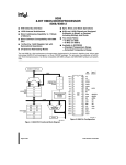
Intel Corp., 8-Bit Embedded Controllers, 1990.
Siemens Corp., Microcontroller Component 80515, 1985.
AMD Corp., Eight-Bit 80C51 Embedded Processors, 1990.
Signetics Corp., Microcontroller Users' Guide, 1989.
6
Chap. 1: 8051 Overview
Component
8031
8051
8751
8053
9761
8751
80C31
80C51
87C51
8032
8052
8752
80C32
80C52
87C52
8044
8344
8744
80535
80515
80C535
80C515
80532
80512
80C152
83C152
80C154
83C154
85C154
80C51FA
83C51FA
87C51FA
83C51FB
87C51FB
83C51FB
87C51FB
80C537
80C517
80C451
83C451
87C451
80C452
83C452
87C452
80C552
83C552
87C552
80C652
83C652
87C652
83C654
87C654
83C752
87C752
83C751
87C751
80C521
80C321
87C521
80C541
87C541
80C851
83C851
Tech.
HMOS
HMOS
HMOS
HMOS
HMOS
HMOS
CMOS
CMOS
CMOS
HMOS
HMOS
HMOS
CMOS
CMOS
CMOS
HMOS
HMOS
HMOS
HMOS
HMOS
CHMOS
CHMOS
HMOS
HMOS
CHMOS
CHMOS
CMOS
CMOS
CMOS
CHMOS
CHMOS
CHMOS
CHMOS
CHMOS
CHMOS
CHMOS
CHMOS
CHMOS
CMOS
CMOS
CMOS
CHMOS
CHMOS
CHMOS
CMOS
CMOS
CMOS
CMOS
CMOS
CMOS
CMOS
CMOS
CMOS
CMOS
CMOS
CMOS
CMOS
CMOS
CMOS
CMOS
CMOS
CMOS
CMOS
ROM
(Kbytes)
0
4
4
8
8
8
0
4
4
0
8
8
0
8
8
4
0
4
0
8
0
8
0
4
0
8
0
16
16
0
8
8
16
16
32
32
0
8
0
4
4
0
8
8
0
8
8
0
8
8
16
16
2
2
2
2
0
8
8
16
16
0
4
ROM
RAM # of Serial I/O Type
Type
(bytes) SFRs Serial I/O Type
{
128
21 Start/Stop Async
Masked
128
21 Start/Stop Async
EPROM
128
21 Start/Stop Async
Masked
128
21 Start/Stop Async
EPROM
128
21 Start/Stop Async
EPROM
128
21 Start/Stop Async
{
128
21 Start/Stop Async
Masked
128
21 Start/Stop Async
EPROM
128
21 Start/Stop Async
{
256
26 Start/Stop Async
Masked
256
26 Start/Stop Async
EPROM
256
26 Start/Stop Async
{
256
26 Start/Stop Async
Masked
256
26 Start/Stop Async
EPROM
256
26 Start/Stop Async
Masked
192
34
HDLC/SDLC
{
192
34
HDLC/SDLC
EPROM
192
34
HDLC/SDLC
{
256
41 Start/Stop Async
Masked
256
41 Start/Stop Async
{
256
41 Start/Stop Async
Masked
256
41 Start/Stop Async
{
128
28 Start/Stop Async
Masked
128
28 Start/Stop Async
{
256
56
CSMA/CD
Masked
256
56
CSMA/CD
{
256
27 Start/Stop Async
Masked
256
27 Start/Stop Async
EPROM
256
27 Start/Stop Async
{
256
47 Start/Stop Async
Masked
256
47 Start/Stop Async
EPROM
256
47 Start/Stop Async
Masked
256
47 Start/Stop Async
EPROM
256
47 Start/Stop Async
Masked
256
47 Start/Stop Async
EPROM
256
47 Start/Stop Async
{
256
41 Start/Stop Async
Masked
256
82 Start/Stop Async
{
128
24
Parallel I/F
Masked
128
24
Parallel I/F
EPROM
128
24
Parallel I/F
{
256
55
U.P.I.
{
256
55
U.P.I.
{
256
55
U.P.I.
{
256
54 Start/Stop Async
Masked
256
54 Start/Stop Async
EPROM
256
54 Start/Stop Async
{
256
24 Start/Stop Async
Masked
256
24 Start/Stop Async
EPROM
256
24 Start/Stop Async
Masked
256
24 Start/Stop Async
EPROM
256
24 Start/Stop Async
Masked
64
25
I2C
EPROM
64
25
I2C
Masked
64
20
I2C
EPROM
64
20
I2C
{
256
26 Start/Stop Async
Masked
256
26 Start/Stop Async
EPROM
256
26 Start/Stop Async
Masked
256
26 Start/Stop Async
EPROM
256
26 Start/Stop Async
{
128
21 Start/Stop Async
Masked
128
21 Start/Stop Async
Table 1.1: 8051 variants.
Chapter 2
8051 CROSS ASSEMBLER OVERVIEW
2.1 Introduction
The 8051 Cross Assembler takes an assembly language source le created with a text editor
and translates it into a machine language object le. This translation process is done in
two passes over the source le. During the rst pass, the Cross Assembler builds a symbol
table from the symbols and labels used in the source le. It's during the second pass that
the Cross Assembler actually translates the source le into the machine language object
le. It is also during the second pass that the listing is generated.
The following is a discussion of the syntax required by the Cross Assembler to generate
error free assemblies.
2.2 Symbols
Symbols are alphanumeric representations of numeric constants, addresses, macros, etc. The
legal character set for symbols is the set of letters, both upper and lower case (A..Z,a..z), the
set of decimal numbers (0..9) and the special characters, question mark (?) and underscore
( ). To ensure that the Cross Assembler can distinguish between a symbol and a number,
all symbols must start with either a letter or special character (? or ). The following are
examples of legal symbols:
PI
Serial_Port_Buffer
LOC_4096
?_?_?
In using a symbol, the Cross Assembler converts all letters to upper case. As a result, the
Cross Assembler makes no distinction between upper and lower case letters. For example,
the following two symbols would be seen as the same symbol by the Cross Assembler:
Serial_Port_Buffer
SERIAL_PORT_BUFFER
Symbols can be dened only once. Symbols can be up to 255 characters in length, though
only the rst 32 are signicant. Therefore, for symbols to be unique, they must have a
unique character pattern within the rst 32 characters. In the following example, the rst
two symbols would be seen by the Cross Assembler as duplicate symbols, while the third
and fourth symbols are unique.
BEGINNING_ADDRESS_OF_CONSTANT_TABLE_1
8
Chap. 2: 8051 CROSS ASSEMBLER OVERVIEW
BEGINNING_ADDRESS_OF_CONSTANT_TABLE_2
CONSTANT_TABLE_1_BEGINNING_ADDRESS
CONSTANT_TABLE_2_BEGINNING_ADDRESS
There are certain symbols that are reserved and can't be dened by the user. These reserved
symbols are listed in Appendix C and include the assembler directives, the 8051 instruction
mnemonics, implicit operand symbols, and the following assembly time operators that have
alphanumeric symbols: EQ, NE, GT, GE, LT, LE, HIGH, LOW, MOD, SHR, SHL, NOT,
AND, OR and XOR.
The reserved implicit operands include the symbols A, AB, C, DPTR, PC, R0, R1, R2, R3,
R4, R5, R6, R7, AR0, AR1, AR2, AR3, AR4, AR5, AR6 and AR7. These symbols are used
primarily as instruction operands. Except for AB, C, DPTR or PC, these symbols can also
be used to dene other symbols (see EQU directive in Chapter 5).
The following are examples of illegal symbols with an explanation of why they are illegal:
1ST_VARIABLE
ALPHA#
MOV
LOW
DATA
(Symbols can not start with a number.)
(Illegal character "#" in symbol.)
(8051 instruction mnemonic)
(Assembly operator)
(Assembly directive)
2.3 Labels
Labels are special cases of symbols. Labels are used only before statements that have physical addresses associated with them. Examples of such statements are assembly language
instructions, data storage directives (DB and DW), and data reservation directives (DS and
DBIT). Labels must follow all the rules of symbol creation with the additional requirement
that they be followed by a colon. The following are legal examples of label uses:
TABLE_OF_CONTROL_CONSTANTS:
DB
0,1,2,3,4,5
MESSAGE:
DB
'HELP'
VARIABLES:
DS
10
BIT_VARIABLES: DBIT 16
START:
MOV
A,#23
(Data storage)
(Data storage)
(Data reservation)
(Data reservation)
(Assembly language instruction)
2.4 Assembler Controls
Assembler controls are used to control where the Cross Assembler gets its input source le,
where it puts the object le, and how it formats the listing le. Table 2.1 summarizes the
assembler controls available. Refer to Chapter 6 for a detailed explanation of the controls.
As can be seen in Table 2.1, all assembler controls are prefaced with a dollar sign ($). No
spaces or tabs are allowed between the dollar sign and the body of the control. Also, only
one control per line is permitted. However, comments can be on the same line as a control.
The following are examples of assembler controls:
$TITLE(8051 Program Ver. 1.0)
$LIST
$PAGEWIDTH(132)
Chap. 2: 8051 CROSS ASSEMBLER OVERVIEW
$DATE(date)
$EJECT
$INCLUDE(le)
$LIST
$NOLIST
$MOD51
$MOD52
$MOD44
$NOMOD
$OBJECT(le)
$NOOBJECT
$PAGING
$NOPAGING
$PAGELENGTH(n)
$PAGEWIDTH(n)
$PRINT(le)
$NOPRINT
$SYMBOLS
$NOSYMBOLS
$TITLE(string)
Places date in page header
Places a form feed in listing
Inserts le in source program
Allows listing to be output
Stops outputting the listing
Uses 8051 predened symbols
Uses 8052 predened symbols
Uses 8044 predened symbols
No predened symbols used
Places object output in le
No object le is generated
Break output listing into pages
Print listing w/o page breaks
No. of lines on a listing page
No. of columns on a listing page
Places listing output in le
Listing will not be output
Append symbol table to listing
Symbol table will not be output
Places string in page header
Table 2.1: Cross Assembler controls.
9
10
Chap. 2: 8051 CROSS ASSEMBLER OVERVIEW
EQU
DATA
IDATA
XDATA
BIT
CODE
DS
DBIT
DB
DW
ORG
END
CSEG
DSEG
XSEG
ISEG
BSEG
USING
IF
ELSE
ENDIF
Dene symbol
Dene internal memory symbol
Dene indirectly addressed internal memory symbol
Dene external memory symbol
Dene internal bit memory symbol
Dene program memory symbol
Reserve bytes of data memory
Reserve bits of bit memory
Store byte values in program memory
Store word values in program memory
Set segment location counter
End of assembly language source le
Select program memory space
Select internal memory data space
Select external memory data space
Select indirectly addressed internal
Select bit addressable memory space memory space
Select register bank
Begin conditional assembly block
Alternative conditional assembly block
End conditional assembly block
Table 2.2: Cross Assembler directives.
2.5 Assembler Directives
Assembler directives are used to dene symbols, reserve memory space, store values in
program memory and switch between dierent memory spaces. There are also directives
that set the location counter for the active segment and identify the end of the source le.
Table 2.2 summarizes the assembler directives available. These directives are fully explained
in Chapter 5.
Only one directive per line is allowed, however comments may be included. The following
are examples of assembler directives:
TEN
RESET
EQU
CODE
ORG
10
0
4096
2.6 8051 Instruction Mnemonics
The standard 8051 Assembly Language Instruction mnemonics plus the generic CALL and
JMP instructions are recognized by the Cross Assembler and are summarized in Table 2.3.
See Chapter 4 for the operation of the individual instructions.
When the Cross Assembler sees a generic CALL or JMP instruction, it will try to translate
the instruction into its most byte ecient form. The Cross Assembler will translate a CALL
into one of two instructions (ACALL or LCALL) and it will translate a generic JMP into one
Chap. 2: 8051 CROSS ASSEMBLER OVERVIEW
ACALL
ADDC
ANL
CLR
DA
DIV
INC
JBC
JMP
JNC
JZ
LJMP
MOVC
MUL
ORL
PUSH
RETI
RLC
RRC
SJMP
SWAP
XCHD
CALL
Absolute call
Add with carry
Logical and
Clear
Decimal adjust
Divide
Increment
Jump & clear bit if bit set
Jump
Jump if carry not set
Jump if accumulator zero
Long jump
Move code
Multiply
Inclusive or
Push stack
Return from interrupt
Rotate left thru carry
Rotate right thru carry
Short jump
Swap nibbles
Exchange digits
Generic call
ADD
AJMP
CJNE
CPL
DEC
DJNZ
JB
JC
JNB
JNZ
LCALL
MOV
MOVX
NOP
POP
RET
RL
RR
SETB
SUBB
XCH
XRL
Add
Absolute jump
Compare & jump if not equal
Complement
Decrement
Decrement & jump if not zero
Jump if bit set
Jump if carry set
Jump if bit not set
Jump if accum. not zero
Long call
Move
Move external
No operation
Pop stack
Return
Rotate left
Rotate right
Set bit
Subtract with borrow
Exchange bytes
Exclusive or
Table 2.3: 8051 instruction set mnemonics.
11
12
Chap. 2: 8051 CROSS ASSEMBLER OVERVIEW
of three instructions (SJMP, AJMP or LJMP). The choice of instructions is based on which
one is most byte ecient. The generic CALL or JMP instructions saves the programmer
the trouble of determining which form is best.
However, generic CALLs and JMPs do have their limitations. While the byte eciency
algorithm works well for previously dened locations, when the target location of the CALL
or JMP is a forward location (a location later on in the program), the assembler has no
way of determining the best form of the instruction. In this case the Cross Assembler
simply puts in the long version (LCALL or LJMP) of the instruction, which may not be
the most byte ecient. NOTE that the generic CALLs and JMPs must not be used for the
751/752 device as LCALL and LJMP are not legal instructions for those devices. Instead
use ACALL and AJMP explicitly.
For instructions that have operands, the operands must be separated from the mnemonic
by at least one space or tab. For instructions that have multiple operands, each operand
must be separated from the others by a comma.
Two addressing modes require the operands to be preceded by special symbols to designate
the addressing mode. The AT sign (@) is used to designate the indirect addressing mode. It
is used primarily with Register 0 and Register 1 (R0, R1), but is can also be used with the
DPTR in the MOVX and the Accumulator in MOVC and JMP @A+DPTR instructions.
The POUND sign (#) is used to designate an immediate operand. It can be used to preface
either a number or a symbol representing a number.
A third symbol used with the operands actually species an operation. The SLASH (/) is
used to specify that the contents of a particular bit address is to be complemented before
the instruction operation. This is used with the ANL and ORL bit instructions.
Only one assembly language instruction is allowed per line. Comments are allowed on the
same line as an instruction, but only after all operands have been specied. The following
are examples of instruction statements:
START:
LJMP
MOV
CJNE
ANL
CALL
RET
INIT
@R0,Serial_Port_Buffer
R0 , #TEN, INC_TEN
C,/START_FLAG
GET_BYTE
2.7 Bit Addressing
The period (.) has special meaning to the Cross Assembler when used in a symbol. It is
used to explicitly specify a bit in a bit-addressable symbol. For example, it you wanted to
specify the most signicant bit in the Accumulator, you could write ACC.7, where ACC
was previously dened as the Accumulator address. The same bit can also be selected using
the physical address of the byte it's in. For example, the Accumulator's physical address
is 224. The most signicant bit of the Accumulator can be selected by specifying 224.7. If
the symbol ON was dened to be equal to the value 7, you could also specify the same bit
by either ACC.ON or 224.ON.
Chap. 2: 8051 CROSS ASSEMBLER OVERVIEW
13
2.8 ASCII Literals
Printable characters from the ASCII character set can be used directly as an immediate
operand, or they can used to dene symbols or store ASCII bytes in Program Memory.
Such use of the ASCII character set is called ASCII literals. ASCII literals are identied
by the apostrophe (') delimiter. The apostrophe itself can be used as an ASCII literal. In
this case, use two apostrophes in a row. Below are examples of using ASCII literals.
QUOTE
MOV
EQU
DB
A,#'m'
''''
'8051'
;Load A with 06DH (ASCII m)
;QUOTE defined as 27H (ASCII single quote)
;Store in Program Memory
2.9 Comments
Comments are user dened character strings that are not processed by the Cross Assembler.
A comment begins with a semicolon ( ; ) and ends at the carriage return/line feed pair that
terminates the line. A comment can appear anywhere in a line, but it has to be the last
eld. The following are examples of comment lines:
; Begin initialization routine here
$TITLE(8051 Program Vers. 1.0)
;Place version number here
TEN
EQU
10
;Constant
; Comment can begin anywhere in a line
MOV A,Serial_Port_Buffer
; Get character
2.10 The Location Counter
The Cross Assembler keeps a location counter for each of the ve segments (code, internal
data, external data, indirect internal data and bit data). Each location counter is initialized
to zero and can be modied using Assembler Directives described in Chapter 5.
The dollar sign ($) can be used to specify the current value of the location counter of the
active segment. The following are examples of how this can be used:
JNB FLAG,$
;Jump on self until flag is reset
CPYRGHT: DB
'Copyright, 1983'
CPYRGHT_LENGTH
EQU $-CPYRGHT-1
;Calculate length of copyright message
2.11 Syntax Summary
Since the Cross Assembler essentially translates the source le on a line by line basis, certain
rules must be followed to ensure the translation process is done correctly. First of all, since
the Cross Assembler's line buer is 256 characters deep, there must always be a carriage
return/line feed pair within the rst 256 columns of the line.
A legal source le line must begin with either a control, a symbol, a label, an instruction
mnemonic, a directive, a comment or it can be null (just the carriage return/line feed pair).
Any other beginning to a line will be agged as an error.
14
Chap. 2: 8051 CROSS ASSEMBLER OVERVIEW
Radix
Designator Legal Digits Maximum Legal Number
Binary
Octal
B
O,Q
Decimal
Hexadecimal
0,1
0,1,2,3,4,5,
6,7
D,(default) 0,1,2,3,4,5,
6,7,8,9
H
0,1,2,3,4,5,
6,7,8,9,A,B,
C,D,E,F
1111111111111111B
177777O
177777Q
65535D
65535
0FFFFH
Table 2.4: Cross Assembler number representations.
While a legal source le line must begin with one of the above items, the item doesn't have
to begin in the rst column of the line. It only must be the rst eld of the line. Any
number (including zero) of spaces or tabs, up to the maximum line size, may precede it.
Comments can be placed anywhere, but they must be the last eld in any line.
2.12 Numbers and Operators
The Cross Assembler accepts numbers in any one of four radices: binary, octal, decimal and
hexadecimal. To specify a number in a specic radix, the number must use the correct digits
for the particular radix and immediately following the number with its radix designator.
Decimal is the default radix and the use of its designator is optional. An hexadecimal
number that would begin with a letter digit must be preceded by a 0 (zero) to distinguish it
from a symbol. The internal representation of numbers is 16-bits, which limits the maximum
number possible. Table 2.4 summarizes the radices available.
No spaces or tabs are allowed between the number and the radix designator. The letter
digits and radix designators can be in upper or lower case. The following examples list the
decimal number 2957 in each of the available radices:
101110001101B
5615o or 5615Q
2957 or 2957D
0B8DH, 0b8dh
(Binary)
(Octal)
(Decimal)
(Hexadecimal)
When using radices with explicit bit symbols, the radix designator follows the byte portion
of the address as shown in the following examples:
0E0H.7
200Q.ON
Bit seven of hexadecimal address 0E0
Bit ON of octal address 200
The Cross Assembler also allows assembly time evaluation of arithmetic expressions up to
thirty-two levels of embedded parentheses. All calculations use integer numbers and are
done in sixteen bit precision.
The relational operators test the specied values and return either a True or False. False
is represented by a zero value, True is represented by a non zero value (the True condition
Chap. 2: 8051 CROSS ASSEMBLER OVERVIEW
15
OPERATOR SYMBOL OPERATION
+
Addition
Unary positive
Subtraction
Unary negation (2's complement)
Multiplication
/
Integer division (no remainder)
MOD
Modulus (remainder of integer division)
SHR
Shift right
SHL
Shift left
NOT
Logical negation (1's complement)
AND
Logical and
OR
Inclusive or
XOR
Exclusive or
LOW
Low order 8-bits
HIGH
High order 8-bits
EQ, =
Relational equal
NE, <>
Relational not equal
GT, >
Relational greater than
GE, >=
Relational greater than or equal
LT, <
Relational less than
LE, <=
Relational less than or equal
()
Parenthetical statement
Table 2.5: Cross Assembler arithmetic and relational operations.
actually returns a 16-bit value with every bit set; i.e., 0FFFFH). The relational operators
are used primarily with the Conditional Assembly capability of the Cross Assembler.
Table 2.5 lists the operations available while Table 2.6 lists the operations precedence in
descending order. Operations with higher precedence are done rst. Operations with equal
precedence are evaluated from left to right.
OPERATION
PRECEDENCE
(,)
HIGHEST
HIGH,LOW
,/,MOD,SHR,SHL
+,EQ,LT,GT,LE,GE,NE,=,<,>,<=,>=,<>
NOT
AND
OR,XOR
LOWEST
Table 2.6: Cross Assembler operator precedence.
16
Chap. 2: 8051 CROSS ASSEMBLER OVERVIEW
The following are examples of all the available operations and their result:
HIGH(0AADDH)
LOW(0AADDH)
7*4
7/4
7 MOD 4
1000B SHR 2
1010B SHL 2
10+5
+72
25-17
-1
NOT 1
7 EQ 4, 7 = 4
7 LT 4, 7 < 4
7 GT 4, 7 > 4
7 LE 4, 7 <= 4
7 GE 4, 7 >= 4
7 NE 4, 7 <> 4
1101B AND 0101B
1101B OR 0101B
1101B XOR 0101B
will
will
will
will
will
will
will
will
will
will
will
will
will
will
will
will
will
will
will
will
will
return
return
return
return
return
return
return
return
return
return
return
return
return
return
return
return
return
return
return
return
return
a
a
a
a
a
a
a
a
a
a
a
a
a
a
a
a
a
a
a
a
a
result
result
result
result
result
result
result
result
result
result
result
result
result
result
result
result
result
result
result
result
result
of
of
of
of
of
of
of
of
of
of
of
of
of
of
of
of
of
of
of
of
of
0AAH
0DDH
28
1
3
0010B
101000B
15
72
8
1111111111111111B
1111111111111110B
0
0
0FFFFH
0
0FFFFH
0FFFFH
0101B
1101B
1000B
2.13 Source File Listing
The source le listing displays the results of the Cross Assembler translation. Every line of
the listing includes a copy of the original source line as well as a line number and the Cross
Assembler translation.
For example, in translating the following line taken from the middle of a source le:
TRANS:
MOV
R7,#32
;Set up pointer
the listing will print:
002F 7920
152
TRANS:
MOV
R1,#32
;Set up pointer
The '002F' is the current value of the location counter in hexadecimal. The '7920' is the
translated instruction, also in hexadecimal. The '152' is the decimal line number of the
current assembly. After the line number is a copy of the source le line that was translated.
Another example of a line in the listing le is as follows:
015B 13
=1 267 +2
RRC
A
Here we see two additional elds. The '=1' before the line number gives the current nesting
of include les. The '+2' after the line number gives the current macro nesting. This line
essentially says that this line comes from a second level nesting of a macro that is part of
an include le.
Another line format that is used in the listing is that of symbol denition. In this case the
location counter value and translated instruction elds described above are replaced with
the denition of the symbol. The following are examples of this:
Chap. 2: 8051 CROSS ASSEMBLER OVERVIEW
00FF
REG
67
68
MAX_NUM
COUNTER
EQU
EQU
17
255
R7
The '00FF' is the hexadecimal value of the symbol MAX NUM. Again, '67'is the decimal
line number of the source le and the remainder of the rst line is a copy of the source le.
In the second line above, the 'REG' shows that the symbol COUNTER was dened to be
a general purpose register.
Optionally, a listing can have a page header that includes the name of the le being assembled, title of program, date and page number. The header and its elds are controlled by
specic Assembler Controls (see Chapter 6).
The default case is for a listing to be output as a le on the default drive with the same name
as the entered source le and an extension of .LST. For example, if the source le name
was PROGRAM.ASM, the listing le would be called PROGRAM.LST. Or if the source
le was called MODULE1, the listing le would be stored as MODULE1.LST. The default
can be changed using the $NOPRINT and $PRINT() Assembler Controls (see Chapter 6).
2.14 Object File
The 8051 Cross Assembler also creates a machine language object le. The format of the
object le is standard Intel Hexadecimal. This Hexadeciaml le can be used to either
program EPROMs using standard PROM Programmers for prototyping, or used to pattern
masked ROMs for production.
The default case is for the object le to be output on the default drive with the same name
as the rst source le and an extension of .HEX. For example, if the source le name was
PROGRAM.ASM, the object le would be called PROGRAM.HEX. Or if the source le
was called MODULE1, the object le would be stored as MODULE1.HEX. The default can
be changed using the $NOOBJECT and $OBJECT() Assembler Controls (see Chapter 6).
18
Chap. 2: 8051 CROSS ASSEMBLER OVERVIEW
Chapter 3
RUNNING THE 8051 CROSS ASSEMBLER ON PC-DOS/MS-DOS
SYSTEMS
3.1 Cross Assembler Files
The oppy disk you receive with this manual is an 8 sector, single-sided, double density
disk. This distribution disk will contain the following les:
ASM51.EXE The Cross Assembler program itself
MOD152
Source le for the $MOD152 control
MOD154
Source le for the $MOD154 control
MOD252
Source le for the $MOD252 control
MOD44
Source le for the $MOD44 control
MOD451
Source le for the $MOD451 control
MOD452
Source le for the $MOD452 control
MOD51
Source le for the $MOD51 control
MOD512
Source le for the $MOD512 control
MOD515
Source le for the $MOD515 control
MOD517
Source le for the $MOD517 control
MOD52
Source le for the $MOD52 control
MOD521
Source le for the $MOD521 control
MOD552
Source le for the $MOD552 control
MOD652
Source le for the $MOD652 control
MOD751
Source le for the $MOD751 control
MOD752
Source le for the $MOD752 control
MOD851
Source le for the $MOD851 control
There will also be one or more les with an extension of .ASM. These are sample programs.
Listings of these programs can be found in Appendix A.
DON'T USE THE DISTRIBUTION DISK. MAKE WORKING AND BACKUP COPIES
FROM THE DISTRIBUTION DISK AND THEN STORE THE DISTRIBUTION DISK
IN A SAFE PLACE.
3.2 Minimum System Requirements
With DOS 2.0 or later - 96K RAM 1 Floppy Disk Drive
20 Chap. 3: RUNNING THE 8051 CROSS ASSEMBLER ON PC-DOS/MS-DOS SYSTEMS
3.3 Running the Cross Assembler
Once you've created an 8051 assembly language source text le in accordance with the
guidelines in Chapter 2, you are now ready to run the Cross Assembler. Make sure your
system is booted and the DOS prompt ( A> ) appears on the screen. Place the disk with
the 8051 Cross Assembler on it in the drive and simply type (in all the following examples,
the symbol <CR> is used to show where the ENTER key was hit):
ASM51<CR>
If the 8051 Cross Assembler disk was placed in a drive other than the default drive, the
drive name would have to be typed rst. For example, if the A drive is the default drive,
and the 8051 Cross Assembler is in the B drive, you would then type:
B:ASM51<CR>
After loading the program from the disk, the program's name, its version number and
general copyright information will be dis- played on the screen. The Cross Assembler then
asks for the source le name to begin the assembly process.
Source file drive and name [.ASM]:
At this point, if you have only one oppy disk drive and the 8051 Cross Assembler and
source les are on separate disks, remove the disk with the 8051 Cross Assembler on it and
replace it with your source le disk.
Next, enter the source le name. If no extension is given, the Cross Assembler will assume
an extension of .ASM. If no drive is given, the Cross Assembler will assume the default
drive. Since in every case where no drive is given, the Cross Assembler assumes the default
drive, it is generally a good practice to change the default drive to the drive with your
source les.
An alternative method for entering the source le is in the command line. In this case, after
typing in ASM51, type in a space and the source le name (again if no extension is given,
source le on the command line:
A>ASM51 B:CONTROL.A51<CR>
After the source le name has been accepted, the Cross Assembler will begin the translation
process. As it starts the rst pass of its two pass process, it will print on the screen:
First pass
At the completion of the rst pass, and as it starts its second pass through the source le,
the Cross Assembler will display:
Second pass
When second pass is completed, the translation process is done and the Cross Assembler
will print the following message:
ASSEMBLY COMPLETE, XX ERRORS FOUND
XX is replaced with the actual number of errors that were found. Disk I/O may continue
for a while as the Cross Assembler appends the symbol table to the listing le.
Chap. 3: RUNNING THE 8051 CROSS ASSEMBLER ON PC-DOS/MS-DOS SYSTEMS 21
3.4 Example Running the Cross Assembler
The following is an example of an actual run. The Cross Assembler will take the source le
SAMPLE.ASM from Drive A (default drive).
Again, the symbol <CR> is used to show where the ENTER key was hit.
A>ASM51<CR>
8 0 5 1
C R O S S
Version
A S S E M B L E R
1.2
(c) Copyright 1984, 1985, 1986, 1987, 1988, 1989, 1990
MetaLink Corporation
Source file drive and name [.ASM]: sample<CR>
First pass
Second pass
ASSEMBLY COMPLETE, 0 ERRORS FOUND
3.5 DOS Hints and Suggestions
If you are using DOS 2.0 or later, you may want to use the BREAK ON command before you
run the Cross Assembler. This will allow you to abort (Ctrl-Break) the Cross Assembler at
any time. Otherwise, you will only be able to abort the Cross Assembler after it completes
a pass through the source le. If you are assembling a large le, this could cause you a
several minute wait before the Cross Assembler aborts.
The reason for this it that the default condition for DOS to recognizes a Ctrl-Break is
when the program (in this case the Cross Assembler) does keyboard, screen or printer I/O.
Unfortunately, the assembler does this very rarely (once each pass). By using the BREAK
ON command, DOS will recognize a Ctrl- Break for all I/O, including disk I/O. Since the
Cross Assembler is constantly doing disk I/O, with BREAK ON you can abort almost
immediately by hitting the Ctrl-Break keys.
So much for the good news. However, aborting a program can cause some undesirable
side-eects. Aborting a program while les are open causes DOS to drop some information
about the open les. This results in disk sectors being allocated when they are actually
free. Your total available disk storage shrinks. You should make the practice of running
CHKDSK with the /F switch periodically to recover these sectors.
The Cross Assembler run under DOS 2.0 or later supports redirection. You can specify the
redirection on the command line. Use the following form:
22 Chap. 3: RUNNING THE 8051 CROSS ASSEMBLER ON PC-DOS/MS-DOS SYSTEMS
ASM51 <infile >outfile
"inle" and "outle" can be any legal le designator. The Cross Assembler will take its
input from the "inle" instead of the keyboard and will send its output to "outle" instead
of the screen.
Note that redirection of input in ASM51 is redundant since the assembler is an absolute
assembler and has no command line options other than the le name argument.
Output redirection is useful for speeding up the assembly process. Because assembly-time
errors are directed to std err in DOS, an error listing cannot be redirected to a le
To make the .lst le serve as an error-only le, use the Cross Assembler Controls $PRINT
(create a list le) $NOLIST (turn the listing o). Use the Cross Assembler Controls
$NOSYMBOLS to further compress the error-only listing resulting from the manipulation of the list le controls. See Chapter 6 for more information. The errors will be listed
in the .lst le, as usual.
If the control $NOPRINT (see Chapter 6) is active, all error messages are send to the screen.
3.6 References
1. IBM Corp., Disk Operating System, Version 1.10, May 1982.
2. IBM Corp., Disk Operating System, Version 2.00, January 1983.
Chapter 4
8051 INSTRUCTION SET
4.1 Notation
Below is an explanation of the column headings and column contents of the 8051 Instruction
Set Summary Table Table 4.1 that follows in this chapter.
MNEMONIC: The MNEMONIC column contains the 8051 Instruction Set Mnemonic
and a brief description of the instruction's operation.
OPERATION: The OPERATION column describes the 8051 Instruction Set in unambiguous symbology. Following are the denitions of the symbols used in this column.
24
Chap. 4: 8051 INSTRUCTION SET
<n:m>
Bits of a register inclusive. For example, PC<10:0>
means bits 0 through 10 inclusive of the PC. Bit 0 is
always the least signicant bit.
+
Binary addition
Binary 2s complement subtraction
/
Unsigned integer division
X
Unsigned integer multiplication
Binary complement (1s complement)
^
Logical And
v
Inclusive Or
v
Exclusive Or
>
Greater than
<>
Not equal to
=
Equals
(
Is written into. For example, A + SOper -> A means
the result of the binary addition between A and the
Source Operand is written into A.
A
The 8-bit Accumulator Register
AC
The Auxiliary Carry Flag in the Program Status Word
CF
The Carry Flag in the Program Status Word
DOper
The Destination Operand used in the instruction
DPTR
16-bit Data Pointer
Intrupt Active Flag Internal Flag that holds o interrupts until the Flag is
cleared
Jump Relative to PC A Jump that can range between -128 bytes and +127
bytes from the PC value of the next instruction
Paddr
A 16-bit Program Memory address
PC
The 8051 Program Counter. This 16-bit register points
to the byte in the Program Memory space that is
fetched as part of the instruction stream.
PM(addr)
Byte in Program Memory space pointed to by addr
Remainder
Integer remainder of unsigned integer division
SOper
The Source Operand used in the instruction
SP
8-bit Stack Pointer
STACK
The Last In First Out data structure that is controlled
by the 8-bit Stack Pointer (SP). Sixteen bit quantities
are pushed on the stack low byte rst.
DEST ADDR MODE/SRC ADDR MODE: These two columns specify the Destination and Source Addressing Modes, respectively, that are available for each instruction.
Chap. 4: 8051 INSTRUCTION SET
25
AB
The Accumulator-B Register pair.
Accumulator Operand resides in the accumulator.
Bit Direct
Operand is the state of the bit specied by the Bit
Memory address.
Carry Flag Operand is the state of the 1-bit Carry ag in the Program Status Word (PSW).
Data Pointer Operand resides in the 16-bit Data Pointer Register.
Direct
Operand is the contents of the specied 8-bit Internal
Data Memory address from 0 (00H) to 127 (7FH) or a
Special Function Register address.
Indirect
Operand is the contents of the address contained in the
register specied.
Immediate
Operand is the next sequential byte after the instruction in Program Memory space.
Prog Direct 16-bit address in Program Memory Space.
Prog Indir
Operand in Program Memory Space is the address contained in the register specied.
Register
Operand is the contents of the register specied.
Stack
Operand is on the top of the Stack.
ASSEMBLY LANGUAGE FORM: This column contains the correct format of the
instructions that are recognized by the Cross Assembler.
A
Accumulator.
AB
Accumulator-B Register pair.
C
Carry Flag.
Baddr Bit Memory Direct Address.
Daddr Internal Data Memory or Special Function Register Direct Address.
data 8-bit constant data.
data16 16-bit constant data.
DPTR 16-bit Data Pointer Register.
PC
16-bit Program Counter.
Paddr 16-bit Program Memory address.
Ri
Indirect Register. R0 or R1 are the only indirect
registers.
Ro
8-bit oset for Relative Jump.
Rn
Implicit Register. Each register bank has 8 general
purpose registers, designated R0, R1, R2, R3, R4, R5,
R6, R7.
HEX OPCODE: This column gives the machine language hexadecimal opcode for each
8051 instruction.
B: This column gives the number of bytes in each 8051 instruction.
C: This column gives the number of cycles of each 8051 instruction. The time value of a
cycle is dened as 12 divided by the oscillator frequency. For example, if running an
8051 family component at 12 MHz, each cycle takes 1 microsecond.
PSW: This column identies which condition code ags are aected by the operation of
the individual instructions. The condition code ags available on the 8051 are the
Carry Flag, CF, the Auxiliary Carry Flag, AC, and the Overow Flag, OV.
26
Chap. 4: 8051 INSTRUCTION SET
It should be noted that the PSW is both byte and bit directly addressable. Should
the PSW be the operand of an instruction that modies it, the condition codes could
be changed even if this column states that the instruction doesn't aect them.
0 Condition code is cleared
1 Condition code is set
Condition code is modied by instruction
- Condition code is not aected by instruction
4.2 8051 Instruction Set Summary
Mnemonic
ACALL
2K in Page (11 bits)
Absolute Call
ADD
Add Operand to
Accum
ADDC
Add Operand with
Carry to Accum
AJMP
2K in Page (11 bits)
Absolute Jump
ANL
Logical AND of Source
Operand with
Destination Operand
Operation
Dest Src Assembly
Addr Addr Language
Mode Mode Form
PC + 2 )STACK
Prog Dir
ACALL Paddr
SP + 2 )SP
Paddr<10:0>)PC<10:0>
PC<15:11>)PC<15:11>
A + SOper )A
Accum Immed ADD A,#data
Accum Direct ADD A,Daddr
Accum Indirect ADD A,@Ri
Accum Reg
ADD A,Rn
A + SOper + C )A
Accum Immed ADDC A,#data
Accum Direct ADDC A,Daddr
Accum Indirect ADDC A,@Ri
Accum Reg
ADDC A,Rn
Paddr<10:0>)PC<10:0> Prog Dir
AJMP Paddr
PC<15:11>)PC<15:11>
SOper ^ DOper )DOper Direct Accum ANL Daddr,A
Direct Immed ANL Daddr,#data
Accum Immed ANL A,#data
Accum Direct ANL A,Daddr
Accum Indirect ANL A,@Ri
Accum Reg
ANL A,Rn
SOper ^ CF )CF
CF
Bit Dir ANL C,Baddr
SOper ^ CF )CF
CF
Bit Dir ANL C,/Baddr
Logical AND of Source
Operand with CF
Logical AND of Source
Operand Complemented
with CF
CJNE
Compare Operands and Jump Relative to PC if
Accum
Jump Relative if not
DOper <>SOper
Accum
Equal
Indirect
Reg
CLR
Clear Accum
0 )A
Accum
Clear CF
0 )CF
CF
Clear Bit Operand
0 )DOper
Bit Dir
CPL
A )A
Complement Accum
Accum
CF )CF
Complement CF
CF
Complement Bit Operand DOper )DOper
Bit Dir
DA
Decimal Adjust
If (A<3:0>>9) v AC
Accum
Accum for
then A<3:0>+6 )A<3:0>
Addition
If (A<7:4>>9) v CF
then A<7:4>+6 )A<7:4>
DEC
Decrement Operand
DOper - 1 )DOper
Accum
Direct
Indirect
Reg
Immed
Direct
Immed
Immed
Hex B C PSW
Code
CF AC OV
see 2 2 note 1
-
-
24
25
26,27
28-2F
34
35
36,37
38-3F
see
note 2
2
2
1
1
2
2
1
1
2
1 *
1
1
1
1 *
1
1
1
2 -
*
*
*
*
-
-
52
53
54
55
56,57
58-5F
82
B0
2
3
2
2
1
1
2
2
1 2
1
1
1
1
2 *
2 *
-
-
-
-
CJNE A,#data,Ro
CJNE A,Daddr,Ro
CJNE @Ri,#data,Ro
CJNE Rn,#data,Ro
CLR A
CLR C
CLR Baddr
CPL A
CPL C
CPL Baddr
DA A
B4 3
B5 3
B6,B7 3
B8-BF 3
E4 1
C3 1
C2 2
F4 1
B3 1
B2 2
D4 1
2
2
2
2
1
1
1
1
1
1
1
DEC A
DEC Daddr
DEC @Ri
DEC Rn
14
15
16,17
18-1F
1 1
1
1
Table 4.1: 8051 instruction set.
1
2
1
1
*
- see
note 3
0
*
*
- - - - - - - see
note 4
-
-
Chap. 4: 8051 INSTRUCTION SET
Mnemonic
Operation
DIV
Divide Accum by
A / B )A
B Reg
Remainder )B
DJNZ
Decrement Operand and DOper - 1 )DOper
Jump Relative if Not If DOper <>0 then Jump
Zero
Relative to PC
INC
Increment Operand
DOper + 1 )DOper
JB
Jump Relative if Bit
Operand is Set
JBC
Jump Relative if Bit
Operand is Set and
Clear Bit Operand
JC
Jump Relative if
CF is Set
JMP
Jump Indirect
JNB
Jump Relative if Bit
Operand is Clear
JNC
Jump Relative if
CF is Clear
JNZ
Jump Relative if the
Accum is Not
Zero
JZ
Jump Relative if the
Accum is Zero
LCALL
Long (16 bits) Call
LJMP
Long (16 bits)
Absolute Jump
MOV
Move Source Operand
to Destination
Operand
Src
Assembly
Addr Language
Mode Form
Hex B C PSW
Code
CF AC OV
AB
DIV AB
Direct
Reg
DJNZ Daddr,Ro
DJNZ Rn,Ro
1 4 0 - *
see
note 5
D5
3 2 - - D8-DF 2 2
Accum
Direct
Indirect
Reg
Data Ptr
Bit Dir
INC A
INC Daddr
INC @Ri
INC Rn
INC DPTR
JB Baddr,Ro
04
05
06,07
08-0F
A3
20
1
2
1
1
1
3
Bit Dir
JBC Baddr,Ro
10
CF
JC Ro
40
3 2 * * *
see
note 6
2 2 - - -
Prog Indir
JMP @A+DPTR
73
1 2 -
-
-
Bit Dir
JNB Baddr,Ro
30
3 2 -
-
-
CF
JNC Ro
50
2 2 -
-
-
Accum
JNZ Ro
70
2 2 -
-
-
If A<7:0>= 0 then
Jump Relative to PC
PC + 3 )STACK
SP + 2 )SP
Paddr<15:0>)PC<15:0>
Paddr<15:0>)PC<15:0>
Accum
JZ Ro
60
2 2 -
-
-
Prog Dir
LCALL Paddr
12
3 2 -
-
-
Prog Dir
LJMP Paddr
02
3 2 -
-
-
SOper )DOper
Accum
Accum
Accum
Accum
Direct
Direct
Direct
Direct
Direct
Indirect
Indirect
Indirect
Reg
Reg
Reg
Data Ptr
Bit Dir
CF
1 - 1
1
1
1
2
2
2
2
1
1
2
1
1
2
2
2 - 1 * -
-
If DOper = 1 then Jump
Relative to PC
If DOper = 1 then
0 )DOper and Jump
Relative to PC
If CF = 1 then Jump
Relative to PC
DPTR<15:0>+ A<7:0>
)PC<15:0>
If DOper = 0 then Jump
Relative to PC
If CF = 0 then Jump
Relative to PC
If A<7:0><>0 then
Jump Relative to PC
SOper )DOper
Move CF to Bit
Destination Operand
Move Bit Destination
Operand to CF
MOVC
Move byte from
Program Memory to
Dest
Addr
Mode
27
CF )DOper
DOper )CF
PM(DPTR<15:0>+ A<7:0>) Accum
)A<7:0>
PM(PC<15:0>+ A<7:0>) Accum
)A<7:0>
MOVX
Move byte from
SOper )A
Accum
External Data Memory
Accum
to the Accum
Move byte in the
A )DOper
Indirect
Accum to
Indirect
External Data Memory
MUL
Multiply Accum
A X B )B,A
AB
by B Reg
(see note 7)
Immed
Direct
Indirect
Reg
Accum
Immed
Direct
Indirect
Reg
Accum
Immed
Direct
Accum
Immed
Direct
Immed
CF
Bit Dir
84
MOV A,#data
74
MOV A,Daddr
E5
MOV A,@Ri
E6,E7
MOV A,Rn
E8-EF
MOV Daddr,A
F5
MOV Daddr,#data 75
MOV Daddr,Daddr 85
MOV Daddr,@Ri
86,87
MOV Daddr,Rn
88-8F
MOV @Ri,A
F6,F7
MOV @Ri,#data
76,77
MOV @Ri,Daddr
A6,A7
MOV Rn,A
F8-FF
MOV Rn,#data
78-7F
MOV Rn,Daddr
A8-AF
MOV DPTR,#data16 90
MOV Baddr,C
92
MOV C,Baddr
A2
2
2
1
1
2
3
3
2
2
1
2
2
1
2
2
3
2
2
1 1
1
1
2
2 -
-
-
-
-
-
Prog Ind MOVC A,@A+DPTR 93
Prog Ind MOVC A,@A+PC 83
1 2 1 2 -
-
-
Indirect
Indirect
Accum
Accum
-
-
MOVX A,@Ri
MOVX A,@DPTR
MOVX @Ri,A
MOVX @DPTR,A
E2,E3
E0
F2,F3
F0
1
1
1
1
-
-
MUL AB
A4
1 4 0 -
*
Table 4.1: 8051 instruction set (continued).
2 2
2 2
28
Chap. 4: 8051 INSTRUCTION SET
Mnemonic
NOP
No Operation
ORL
Logical Inclusive OR
of Source Operand
with Destination
Operand
Operation
Dest Src Assembly
Addr Addr Language
Mode Mode Form
SOper v DOper )DOper Direct
Direct
Accum
Accum
Accum
Accum
SOper v CF )CF
CF
Logical Inclusive OR
of Source Operand
with CF
Logical Inclusive OR SOper v CF )CF
CF
of Source Operand
Complemented with CF
POP
Pop Stack and Place STACK )DOper
Direct
in Destination Operand SP - 1 )SP
PUSH
Push Source Operand SP + 1 )SP
Stack
onto Stack
SOper )STACK
RET
Return from
STACK )PC<15:8>
Subroutine
SP - 1 )SP
STACK )PC<7:0>
SP - 1 )SP
RETI
Return from
STACK )PC<15:8>
Interrupt Routine
SP - 1 )SP
STACK )PC<7:0>
SP - 1 )SP
0 )Intrupt Active Flag
RL
Rotate Accum
A<6:0>)A<7:1>
Accum
Left One Bit
A<7>)A<0>
RLC
Rotate Accum
A<6:0>)A<7:1>
Accum
Left One Bit Thru
CF )A<0>
the CF
A<7>)CF
RR
Rotate Accum
A<7:1>)A<6:0>
Accum
Right One Bit
A<0>)A<7>
RRC
Rotate Accum
A<7:1>)A<6:0>
Accum
Right One Bit Thru CF )A<7>
the CF
A<0>)CF
SETB
Set Bit Operand
1 )CF
CF
1 )DOper
Bit Dir
SJMP
Short (8 bits)
Jump Relative to PC
Relative Jump
SUBB
Subtract Operand with A - SOper - CF )A
Accum
Borrow from the
Accum
Accum
Accum
Accum
SWAP
Swap Nibbles within A<7:4>)A<3:0>
Accum
the Accum
A<3:0>)A<7:4>
XCH
Exchange bytes of the SOper<7:0>)A<7:0> Accum
Accum and the
A<7:0>)SOper<7:0> Accum
Source Operand
Accum
XCHD
Exchange the Least
SOper<3:0>)A<3:0> Accum
Signicant Nibble of A<3:0>)SOper<3:0>
the Accum and
the Source Operand
XRL
Logical Exclusive OR SOper v DOper )DOper Direct
of Source Operand
Direct
with Destination
Accum
Operand
Accum
Accum
Accum
Hex B C PSW
Code
CF AC OV
NOP
00
Accum ORL Daddr,A
42
Immed ORL Daddr,#data 43
Immed ORL A,#data
44
Direct ORL A,Daddr
45
Indirect ORL A,@Ri
46,47
Reg
ORL A,Rn
48-4F
Bit Dir ORL C,Baddr
72
1
2
3
2
2
1
1
2
1 1 2
1
1
1
1
2 *
-
-
-
-
Bit Dir ORL C,/Baddr
A0
2 2 *
-
-
Stack
D0
2 2 -
-
-
Direct PUSH Daddr
C0
2 2 -
-
-
RET
22
1 2 -
-
-
RETI
32
1 2 -
-
-
RL A
23
1 1 -
-
-
RLC A
33
1 1 *
-
-
RR A
03
1 1 -
-
-
RRC A
13
1 1 *
-
-
SETB C
SETB Baddr
SJMP Ro
D3
D2
80
1 1 1
2 1 2 2 -
-
-
Immed SUBB A,#data
Direct SUBB A,Daddr
Indirect SUBB A,@Ri
Reg
SUBB A,Rn
SWAP A
94
95
96,97
98-9F
C4
2
2
1
1
1
1 *
1
1
1
1 -
*
*
-
-
Direct XCH A,Daddr
Indirect XCH A,@Ri
Reg
XCH A,Rn
Indirect XCHD A,@Ri
C5 2
C6,C7 1
C8-CF 1
D6,D7 1
1 1
1
1 -
-
-
-
-
1 2
1
1
1
1
-
-
POP Daddr
Accum XRL Daddr,A
62
Immed XRL Daddr,#data 63
Immed XRL A,#data
64
Direct XRL A,Daddr
65
Indirect XRL A,@Ri
66,67
Reg
XRL A,Rn
68-6F
Table 4.1: 8051 instruction set (continued).
2
3
2
2
1
1
Chapter 5
8051 CROSS ASSEMBLER DIRECTIVES
5.1 Introduction
The 8051 Cross Assembler Directives are used to dene symbols, reserve memory space,
store values in program memory, select various memory spaces, set the current segment's
location counter and identify the end of the source le.
Only one directive per line is allowed, however comments may be included. The remaining
part of this chapter details the function of each directive.
5.2 Symbol Denition Directives
5.2.1 EQU Directive
The EQUate directive is used to assign a value to a symbol. It can also be used to specify
user dened names for the implicit operand symbols predened for the Accumulator (i.e.,
A) and the eight General Purpose Registers (i.e., R0 thru R7).
The format for the EQU directive is: symbol, followed by one or more spaces or tabs,
followed by EQU, followed by one or more spaces or tabs, followed by a number, arithmetic
expression, previously dened symbol (no forward references allowed) or one of the allowed
implicit operand symbols (e.g., A, R0, R1, R2, R3, R4, R5, R6, R7), followed by an optional
comment.
Below are examples of using the EQU Directive:
TEN
COUNTER
EQU
EQU
10
R7
ALSO_TEN
EQU
TEN
FIVE
A_REG
EQU
EQU
TEN/2
A
ASCII_D
EQU
'D'
;Symbol equated to a number
;User defined symbol for the implicit
;operand symbol R7. COUNTER can now
;be used wherever it is legal to use
;R7. For example the instruction
;INC R7 could now be written INC COUNTER.
;Symbol equated to a previously defined
;symbol.
;Symbol equated to an arithmetic exp.
;User defined symbol for the implicit
;operand symbol A.
;Symbol equated to an ASCII literal
30
Chap. 5: 8051 CROSS ASSEMBLER DIRECTIVES
5.2.2 SET Directive
Similar to the EQU directive, the SET directive is used to assign a value or implicit operand
to a user dened symbol. The dierence however, is that with the EQU directive, a symbol
can only be dened once. Any attempt to dene the symbol again will cause the Cross
Assembler to ag it as an error. On the other hand, with the SET directive, symbols are
redeneable. There is no limit to the number of times a symbol can be redened with the
SET directive.
The format for the SET directive is: symbol, followed by one or more spaces or tabs,
followed by SET, followed by one or more spaces or tabs, followed by a number, arithmetic
expression, previously dened symbol (no forward references allowed) or one of the allowed
implicit operand symbols (e.g., A, R0, R1, R2, R3, R4, R5, R6, R7), followed by an optional
comment.
Below are examples of using the SET Directive:
POINTER
POINTER
SET
SET
R0
R1
;Symbol equated to register 0
;POINTER redefined to register 1
COUNTER
COUNTER
SET
SET
1
COUNTER+1
;Symbol initialized to 1
;An incrementing symbol
5.2.3 BIT Directive
The BIT Directive assigns an internal bit memory direct address to the symbol. If the
numeric value of the address is between 0 and 127 decimal, it is a bit address mapped in
the Internal Memory Space. If the numeric value of the address is between 128 and 255, it
is an address of a bit located in one of the Special Function Registers. Addresses greater
than 255 are illegal and will be agged as an error.
The format for the BIT Directive is: symbol, followed by one or more spaces or tabs,
followed by BIT, followed by one or more spaces or tabs, followed by a number, arithmetic
expression, or previously dened symbol (no forward references allowed), followed by an
optional comment.
Below are examples of using the BIT Directive:
CF
OFF_FLAG
ON_FLAG
BIT
BIT
BIT
0D7H
6
OFF_FLAG+1
;The single bit Carry Flag in PSW
;Memory address of single bit flag
;Next bit is another flag
5.2.4 CODE Directive
The CODE Directive assigns an address located in the Program Memory Space to the
symbol. The numeric value of the address cannot exceed 65535.
The format for the CODE Directive is: symbol, followed by one or more spaces or tabs,
followed by CODE, followed by one or more spaces or tabs, followed by a number, arithmetic
expression, or previously dened symbol (no forward references allowed), followed by an
optional comment.
Chap. 5: 8051 CROSS ASSEMBLER DIRECTIVES
31
Below are examples of using the CODE Directive:
RESET
EXTI0
CODE
CODE
0
RESET + (1024/16)
5.2.5 DATA Directive
The DATA Directive assigns a directly addressable internal memory address to the symbol.
If the numeric value of the address is between 0 and 127 decimal, it is an address of an
Internal Data Memory location. If the numeric value of the address is between 128 and 255,
it is an address of a Special Function Register. Addresses greater than 255 are illegal and
will be agged as an error.
The format for the DATA Directive is: symbol, followed by one or more spaces or tabs,
followed by DATA, followed by one or more spaces or tabs, followed by a number, arithmetic
expression, or previously dened symbol (no forward references allowed), followed by an
optional comment.
Below are examples of using the DATA Directive:
PSW
BUFFER
FREE_SPAC
DATA
DATA
DATA
0D0H
32
BUFFER+16
;Defining the Program Status address
;Internal Data Memory address
;Arithmetic expression.
5.2.6 IDATA Directive
The IDATA Directive assigns an indirectly addressable internal data memory address to the
symbol. The numeric value of the address can be between 0 and 255 decimal. Addresses
greater than 255 are illegal and will be agged as an error.
The format for the IDATA Directive is: symbol, followed by one or more spaces or tabs,
followed by IDATA, followed by one or more spaces or tabs, followed by a number, arithmetic
expression, or previously dened symbol (no forward references allowed), followed by an
optional comment.
Below are examples of using the IDATA Directive:
TOKEN
BYTE_CNT
ADDR
IDATA
IDATA
IDATA
60
TOKEN + 1
TOKEN + 2
5.2.7 XDATA Directive
The XDATA Directive assigns an address located in the External Data Memory Space to
the symbol. The numeric value of the address cannot exceed 65535.
The format for the XDATA Directive is: symbol, followed by one or more spaces or tabs,
followed by XDATA, followed by one or more spaces or tabs, followed by a number, arithmetic expression, or previously dened symbol (no forward references allowed), followed by
an optional comment.
Below are examples of using the XDATA Directive:
32
Chap. 5: 8051 CROSS ASSEMBLER DIRECTIVES
USER_BASE
HOST_BASE
XDATA
XDATA
2048
USER_BASE + 1000H
5.3 Segment Selection Directives
There are ve Segment Selection Directives: CSEG, BSEG, DSEG, ISEG, XSEG, one for
each of the ve memory spaces in the 8051 architecture. The CSEG Directive is used to
select the Program Memory Space. The BSEG Directive is used to select the Bit Memory
Space. The DSEG Directive is used to select the directly addressable Internal Data Memory
Space. The ISEG is used to select the indirectly addressable Internal Data Memory Space.
The XSEG is used to select the External Data Memory Space.
Each segment has its own location counter that is reset to zero during the Cross Assembler
program initialization. The contents of the location counter can be overridden by using the
optional AT after selecting the segment.
The Program Memory Space, or CSEG, is the default segment and is selected when the
Cross Assembler is run.
The format of the Segment Selection Directives are: zero or more spaces or tabs, followed
by the Segment Selection Directive, followed by one or more spaces or tabs, followed by the
optional segment location counter override AT command and value, followed by an optional
comment.
The value of the AT command can be a number, arithmetic expression or previously dened
symbol (forward references are not allowed). Care should be taken to ensure that the
location counter does not advance beyond the limit of the selected segment.
Below are examples of the Segment Selection Directives:
DSEG
;Select direct data segment using
;current location counter value.
BSEG AT 32
;Select bit data segment forcing
;location counter to 32 decimal.
XSEG AT (USER_BASE * 5) MOD 16 ;Arithmetic expressions can be
;used to specify location.
5.4 Memory Reservation and Storage Directives
5.4.1 DS Directive
The DS Directive is used to reserve space in the currently selected segment in byte units.
It can only be used when ISEG, DSEG or XSEG are the currently active segments. The
location counter of the segment is advanced by the value of the directive. Care should be
taken to ensure that the location counter does not advance beyond the limit of the segment.
The format for the DS Directive is: optional label, followed by one or more spaces or tabs,
followed by DS, followed by one or more spaces or tabs, followed by a number, arithmetic
expression, or previously dened symbol (no forward references allowed), followed by an
optional comment.
Below is an example of using the DS Directive in the internal Data Segment. If, for example,
Chap. 5: 8051 CROSS ASSEMBLER DIRECTIVES
33
the Data Segment location counter contained 48 decimal before the example below, it would
contain 104 decimal after processing the example.
SP_BUFFER:
IO_BUFFER:
DSEG
DS
DS
DS
32
16
8
;Select the data segment
;Label is optional
;Reserve a buffer for the serial port
;Reserve a buffer for the I/O
5.4.2 DBIT Directive
The DBIT Directive is used to reserve bits within the BIT segment. It can only be used
when BSEG is the active segment. The location counter of the segment is advanced by the
value of the directive. Care should be taken to ensure that the location counter does not
advance beyond the limit of the segment.
The format for the DBIT Directive is: optional label, followed by one or more spaces or tabs,
followed by DBIT, followed by one or more spaces or tabs, followed by a number, arithmetic
expression, or previously dened symbol (no forward references allowed), followed by an
optional comment.
Below is an example of using the DBIT Directive:
IO_MAP:
BSEG
DBIT
DBIT
16
32
;Select the bit segment
;Label is optional
;Reserve a bit buffer for I/O
5.4.3 DB Directive
The DB Directive is used to store byte constants in the Program Memory Space. It can
only be used when CSEG is the active segment.
The format for the DB Directive is: optional label, followed by one or more spaces or tabs,
followed by DB, followed by one or more spaces or tabs, followed by the byte constants that
are separated by commas, followed by an optional comment.
The byte constants can be numbers, arithmetic expressions, symbol values or ASCII literals.
ASCII literals have to be delimited by apostrophes ( ' ), but they can be strung together
up to the length of the line.
Below are examples of using the DB Directive. If an optional label is used, its value will
point to the rst byte constant listed.
COPYRGHT_MSG:
DB
RUNTIME_CONSTANTS:
DB
DB
MIXED:
DB
'(c) Copyright, 1984'
;ASCII Literal
127,13,54,0,99
17,32,239,163,49
2*8,'MPG',2*16,'abc'
;Table of constants
;Label is optional
;Can mix literals & no.
5.4.4 DW Directive
The DW Directive is used to store word constants in the Program Memory Space. It can
only be used when CSEG is the active segment.
34
Chap. 5: 8051 CROSS ASSEMBLER DIRECTIVES
The format for the DW Directive is: optional label, followed by one or more spaces or tabs,
followed by DW, followed by one or more spaces or tabs, followed by the word constants
that are separated by commas, followed by an optional comment.
The word constants can be numbers, arithmetic expressions, symbol values or ASCII literals.
ASCII literals must be delimited by apostrophes ( ' ), but unlike the DB Directive, only a
maximum of two ASCII characters can be strung together. The rst character is placed in
the high byte of the word and the second character is placed in the low byte. If only one
character is enclosed by the apostrophes, a zero will be placed in the high byte of the word.
Below are examples of using the DW Directive. If an optional label is used, its value will
point to the high byte of the rst word constant listed.
JUMP_TABLE:
RADIX:
DW
DW
DW
RESET,START,END
TEST,TRUE,FALSE
'H',1000H
;Table of
;Optional
;1st byte
;2nd byte
;3rd byte
;4th byte
addresses
label
contains 0
contains 48H (H)
contains 10H
contains 0
5.5 Miscellaneous Directives
5.5.1 ORG Directive
The ORG Directive is used to specify a value for the currently active segment's location
counter. It cannot be used to select segments like the directives above. It can only be used
within a segment when the location counter needs to be changed. Care should be taken to
ensure that the location counter does not advance beyond the limit of the selected segment.
The format of the ORG Directive is: zero or more spaces or tabs, followed by ORG, followed
by one or more spaces or tabs, followed by a number, arithmetic expression, or previously
dened symbol (no forward references are allowed), followed by an optional comment.
Below are examples of the ORG directive.
ORG
ORG
ORG
1000H
RESET
BASE + MODULE_NO
;Location counter set at 4096 decimal
;Previously defined symbol
;Arithmetic expression
5.5.2 USING DIRECTIVE
The USING Directive is used to specify which of the four General Purpose Register banks
is used in the code that follows the directive. It allows the use of the predened register
symbols AR0 thru AR7 instead of the register's direct addresses. It should be noted that
the actual register bank switching must still be done in the code. This directive simplies
the direct addressing of a specied register bank.
The format of the USING Directive is: zero or more spaces or tabs, followed by USING,
followed by one or more spaces or tabs, followed by a number, arithmetic expression, or
previously dened symbol (no forward references are allowed), followed by an optional
comment.
Chap. 5: 8051 CROSS ASSEMBLER DIRECTIVES
35
The number, arithmetic expression, or previously dened symbol must result in a number
between 0 and 3 in order to specify one of the four register banks in the 8051.
The following table maps the specied value in the USING directive with the direct addresses
of the predened symbols.
Predened USING Value
Symbol 0 1 2 3
AR0
0 8 16 24
AR1
1 9 17 25
AR2
2 10 18 26
AR3
3 11 19 27
AR4
4 12 20 28
AR5
5 13 21 29
AR6
6 14 22 30
AR7
7 15 23 31
Below are examples of the USING Directive:
USING
USING
0
1+1+1
;Select addresses for Bank 0
;Arithmetic expressions
5.5.3 END Directive
The END Directive is used to signal the end of the source program to the Cross Assembler.
Every source program must have one and only one END Directive. A missing END Directive, as well as text beyond the occurrence of the END Directive are not allowed and will
be agged as errors.
The format of the END Directive is: zero or more spaces or tabs, followed by END, followed
by an optional comment. All text must appear in the source program before the occurrence
of the END Directive.
Below is an example of the END Directive:
END
;This is the End
5.6 Conditional Assembly Directives
5.6.1 IF, ELSE and ENDIF Directive
The IF, ELSE and ENDIF directives are used to dene conditional assembly blocks. A
conditional assembly block begins with an IF statement and must end with the ENDIF
directive. In between the IF statement and ENDIF directive can be any number of assembly
language statements, including directives, controls, instructions, the ELSE directive and
nested IF-ENDIF conditional assembly blocks.
The IF statement starts with the keyword IF, followed by one or more spaces or tabs,
followed by a number, arithmetic expression, or previously dened symbol (no forward references are allowed), followed by an optional comment. The number, arithmetic expression
or symbol is evaluated and if found to be TRUE (non- zero), the assembly language statements are translated up to the next ELSE or ENDIF directives. If the IF statement was
36
Chap. 5: 8051 CROSS ASSEMBLER DIRECTIVES
evaluated FALSE (zero), the assembly language statements are considered null up to the
next ELSE or ENDIF directives.
If an optional ELSE appears in the conditional assembly block, the assembly language statements following are handled oppositely from the assembly language statements following
the IF statement. In other words, if the IF statement was evaluated TRUE, the statements
following it are translated, while the statements following the ELSE will be handled as if
they were null. On the other hand, if the IF statement was evaluated FALSE, only the
assembly language statements following the ELSE directive would be translated.
IF-ELSE-ENDIF conditional assembly blocks can be nested up to 255 levels deep. The
following are some examples of conditional assembly blocks. This rst conditional assembly
block simply checks the symbol DEBUG. If DEBUG is non-zero, the MOV and CALL
instructions will be translated by the Cross Assembler.
IF (DEBUG)
MOV
CALL
ENDIF
A,#25
OUTPUT
The next example used the optional ELSE directive. If SMALL MODEL is zero, only the
statements following the ELSE directive will be translated.
IF (SMALL_MODEL)
MOV R0,#BUFFER
MOV A,@R0
ELSE
MOV R0,#EXT_BUFFER
MOVX A,@R0
ENDIF
The last example shows nested conditional assembly blocks. Conditional assembly blocks
can be nested up to 255 levels deep. Every level of nesting must have balanced IF-ENDIF
statements.
IF (VERSION > 10)
CALL DOUBLE_PRECISION
CALL UPDATE_STATUS
IF (DEBUG)
CALL DUMP_REGISTERS
ENDIF
ELSE
CALL SINGLE_PRECISION
CALL UPDATE_STATUS
IF (DEBUG)
CALL DUMP_REGISTERS
ENDIF
ENDIF
_
\
>
_/
Nested
Block
\
|
|
|
|
|
>
_
\
>
_/
Nested
Block
|
|
|
|
|
_/
Outer Block
Chapter 6
8051 CROSS ASSEMBLER CONTROLS
6.1 Introduction
Assembler controls are used to control where the Cross Assembler gets its input source le,
where it stores the object le, how it formats and where it outputs the listing.
All Assembler controls are prefaced with a dollar sign, ($). No spaces or tabs are allowed
between the dollar sign and the body of the control. Also, only one control per line is
permitted. Comments are allowed on the same line as an Assembler control.
There are two types of controls, Primary controls and General controls. Primary controls
can be invoked only once per assembly. If an attempt is made to change a previously invoked
primary control, the attempt is ignored. For example, if $NOPRINT is put on line 1 of
the source le and $PRINT is put on line 2, the $PRINT control will be ignored and the
listing will not be output. General controls can be invoked any number of times in a source
program.
There are two legal forms for each Assembler control, the full form and the abbreviated
form. The two forms can be used inter- changeable in the source program.
Below is a description of each Assembler control. Assembler controls with common functionality are grouped together.
6.2 Assembler Control Descriptions
6.2.1 $DATE(date)
Places the ASCII string enclosed by parenthesis in the date eld of the page header. The
ASCII string can be from 0 to 9 characters long.
CONTROL:
ABBREV:
TYPE:
DEFAULT:
EXAMPLES:
$DATE(date)
$DA(date)
Primary
No date in page header
$DATE(1-JUL-84)
$DA(7/22/84)
38
Chap. 6: 8051 CROSS ASSEMBLER CONTROLS
6.2.2 $DEBUG(le) and $NODEBUG
These controls determine whether or not a MetaLink Absolute Object Module format le
is created. The MetaLink Absolute Object Module format le is used in conjunction with
MetaLink's MetaICE series of in-circuit-emulators. Among other advantages, it provides
powerful symbolic debug capability in the emulator debug environment. $NODEBUG species that a MetaLink Absolute Object Module le will not be created. $DEBUG species
that a MetaLink Absolute Object Module le will be created. The $DEBUG control allows
any legal le name to be specied as the MetaLink Absolute Object Module lename. If no
lename is specied, a default name is used. The default name used for the le is the source
le name root with a .DBG extension. If the $DEBUG control is used, both a MetaLink
Absolute Object Module le and a standard Intel Hexadecimal format object le can be
generated at the same time. Refer to the $OBJECT control description later in this chapter
for information on controlling the Hexadecimal format object le output.
CONTROL:
ABBREV:
DEFAULT:
TYPE:
EXAMPLES:
$DEBUG(file)
$NODEBUG
$DB(file)
$NODB
$NODEBUG
Primary
$DB(A:NEWNAME.ICE)
$DEBUG
$NOOBJECT
6.2.3 $EJECT
Places a form feed (ASCII 0CH) in the listing output. The $NOPAGING control will
override this control.
CONTROL:
ABBREV:
DEFAULT:
TYPE:
EXAMPLES:
$EJECT
$EJ
No form feeds in listing output
General
$EJECT
$EJ
6.2.4 $INCLUDE(le)
Inserts a le in source program as part of the input source program. The le eld in this
control can be any legal le designator. No extension is assumed, so the whole le name
must be specied. Any number of les can be included in a source program. Includes can
be nested up to 8 level deep. It is important to note that this control inserts les, it does
not chain or concatenate les.
CONTROL:
ABBREV:
DEFAULT:
TYPE:
EXAMPLES:
$INCLUDE(file)
$IC(file)
No file included in source program
General
$INCLUDE(B:COMMON.EQU
$IC(TABLES.ASM)
;Uses default drive
Chap. 6: 8051 CROSS ASSEMBLER CONTROLS
39
6.2.5 $LIST and $NOLIST
These controls determine whether or not the source program listing is output or not. $LIST
will allow the source program listing to be output. $NOLIST stops the source program
listing from being output. The $NOPRINT control overrides the $LIST control.
CONTROL:
ABBREV:
DEFAULT:
TYPE:
EXAMPLES:
$LIST
$NOLIST
$LI
$NOLI
$LIST
General
$NOLIST
$INCLUDE(COMMON.TBL)
$LI
;This will cause the included
;file not to be listed
;Listing continues
6.2.6 $MOD and $NOMOD
Recognizes predened special function register symbols in the source program. This saves
the user from having to dene all the registers in the source program. Appendix B lists the
symbols that are dened by these controls. $NOMOD disables the recognizing function.
These controls access les of the same name that are included with the MetaLink 8051
CROSS ASSEMBLER distribution diskette. When a $MOD control is used in a source
program, it is important that the $MOD le be available to the Cross Assembler. The
Cross Assembler rst looks for the $MOD le on the default drive, if it isn't found there,
the Cross Assembler looks for it on the A: drive. The components supported by each switch
are:
$MOD51:
$MOD52:
$MOD44:
$MOD515:
$MOD512:
$MOD517:
$MOD152:
$MOD451:
$MOD452:
$MOD752:
$MOD751:
$MOD154:
$MOD252:
83C51FB,
$MOD521:
$MOD552:
$MOD652:
$MOD851:
CONTROL:
ABBREV:
DEFAULT:
8051, 8751, 8031, 80C51, 80C31, 87C51, 9761, 8053
8052, 8032, 8752
8044, 8344, 8744
80515, 80535, 80C515, 80C535
80512, 80532
80C517, 80C537
80C152, 83C152, 80C157
80C451. 83C451, 87C451
80C452, 83C452, 87C452
83C752, 87C752
83C751, 87C751
83C514, 80C154, 85C154
80C252, 83C252, 87C252, 80C51FA, 83C51FA, 87C51FA,
87C51FB
80C521, 80C321, 87C521, 80C541, 87C541
80C552, 83C552, 87C552
80C652, 83C652
80C851, 83C851
$MOD51 $MOD52 $MOD44 $MOD152 $MOD515
$MOD512 $MOD451 $MOD452 $MOD751
$MOD752 $MOD154 $MOD252 $MOD521
$MOD552 $MOD652 $MOD517 $MOD851
$NOMOD
$NOMOD
40
Chap. 6: 8051 CROSS ASSEMBLER CONTROLS
TYPE:
Primary
EXAMPLES: $MOD51 $MOD52 $MOD44 $MOD515 $MOD512
$MOD152 $MOD451 $MOD452 $MOD751
$MOD752 $MOD154 $MOD252 $MOD521
$MOD552 $MOD652 $MOD517 $MOD851
$NOMOD
6.2.7 $OBJECT(le) and $NOOBJECT
These controls determine whether or not a standard Intel Hexadecimal format object le is
created. $NOOBJECT species that an object le will not be created. $OBJECT species
that an object le will be created. If other than the default name is to be used for the
object le, the $OBJECT control allows any legal le name to be specied as the object
lename. The default name used for the object le is the source le name root with a .HEX
extension.
CONTROL:
ABBREV:
DEFAULT:
TYPE:
EXAMPLES:
$OBJECT(file)
$NOOBJECT
$OJ(file)
$NOOJ
$OBJECT(source.HEX)
Primary
$OJ(A:NEWNAME.OBJ)
$NOOBJECT
6.2.8 $PAGING and $NOPAGING
These controls specify whether or not the output listing will be broken into pages or will
be output as one continuous listing. When the $NOPAGING control is used, the $EJECT
and $PAGELENGTH controls are ignored. With the $PAGING control, a form feed and
header line is inserted into the output listing whenever an $EJECT control is met, or
whenever the number of lines output on the current page exceeds the value specied by
the $PAGELENGTH control. The header line contains source le name, title (if $TITLE
control was used), date (if $DATE control was used) and page number.
CONTROL:
ABBREV:
DEFAULT:
TYPE:
EXAMPLES:
$PAGING
$NOPAGING
$PI
$NOPI
$PAGING
Primary
$PAGING
$NOPI
6.2.9 $PAGELENGTH(n)
Sets the maximum number of lines, (n), on a page of the output listing. If the maximum is
exceeded, a form feed and page header is inserted in the output listing. This control allows
the number of lines per page to be set anywhere between 10 and 255. If the number of lines
specied is less than 10, pagelength will be set to 10. If the number of lines specied is
greater than 255, pagelength will be set to 255.
Chap. 6: 8051 CROSS ASSEMBLER CONTROLS
41
The $NOPAGING control will override this control.
CONTROL:
ABBREV:
DEFAULT:
TYPE:
EXAMPLES:
$PAGELENGTH(n)
$PL(n)
$PAGELENGTH(60)
Primary
$PAGELENGTH(48)
$PL(58)
6.2.10 $PAGEWIDTH(n)
Sets the maximum number of characters, (n), on a line of the output listing. This control
allows the number of characters per line to be set anywhere between 72 and 132. If the
number specied is less than 72, the pagewidth is set at 72. If the number specied is
greater than 132, the pagewidth is set at 132. If the pagewidth is specied between 72 and
100 and the line being output exceeds the pagewidth specication, the line is truncated at
the specied pagewidth and a carriage return/line feed pair is inserted in the listing. If the
pagewidth is specied to be greater than 100 and the line being output exceed the pagewidth
specication, a carriage return/line feed pair is inserted at the specied pagewidth and the
line will continue to be listed on the next line beginning at column 80.
CONTROL:
ABBREV:
DEFAULT
TYPE:
EXAMPLES:
$PAGEWIDTH(n)
$PW(n)
$PAGEWIDTH(72)
Primary
$PAGEWIDTH(132)
$PW(80)
6.2.11 $PRINT(le) and $NOPRINT
These controls determine whether or not a listing le is created. $NOPRINT species that
a listing le will not be created. $PRINT species that an listing le will be created. If
other than the default name is to be used for the listing le, the $PRINT control allows any
legal le name to be specied as the listing lename. The default name used for the listing
le is the source le name root with a .LST extension.
CONTROL:
ABBREV:
DEFAULT:
TYPE:
EXAMPLES:
$PRINT(file)
$NOPRINT
$PR
$NOPR
$PRINT(source.LST)
Primary
$PRINT(A:CONTROL.OUT)
$NOPR
6.2.12 $SYMBOLS and $NOSYMBOLS
Selects whether or not the symbol table is appended to the listing output. $SYMBOLS
causes the symbol table to be sorted alphabetically by symbol, formatted and output to the
listing le. Along with the symbol name, its value and type are output. Values are output
in hexadecimal. Types include NUMB (number), ADDR (address), REG (register symbol)
42
Chap. 6: 8051 CROSS ASSEMBLER CONTROLS
and ACC (accumulator symbol). If a symbol was of type ADDR, it segment is also output
as either C (code), D (data) or X (external). Other information listed with the symbols is
NOT USED (symbol dened but never referenced), UNDEFINED (symbol referenced but
never dened) and REDEFINEABLE (symbol dened using the SET directive). The type
and value listed for a REDEFINABLE symbol is that of its last denition in the source
program. $NOSYMBOLS does not output the symbol table.
CONTROL:
ABBREV:
DEFAULT:
TYPE:
EXAMPLES:
$SYMBOLS
$NOSYMBOLS
$SB
$NOSB
$SYMBOLS
Primary
$SB
$NOSYMBOLS
6.2.13 $TITLE(string)
Places the ASCII string enclosed by the parenthesis in the title eld of the page header. The
ASCII string can be from 0 to 64 characters long. If the string is greater than 64 characters
or if the width of the page will not support such a long title, the title will be truncated. If
parentheses are part of the string, they must be balanced.
CONTROL:
ABBREV:
DEFAULT:
TYPE:
EXAMPLES:
$TITLE(string)
$TT(string)
No title in page header
Primary
$TITLE(SAMPLE PROGRAM V1.2)
$TT(METALINK (TM) CROSS ASSEMBLER)
Chapter 7
8051 CROSS ASSEMBLER MACRO PROCESSOR
7.1 Introduction
Macros are useful for code that is used repetitively throughout the program. It saves the
programmer the time and tedium of having to specify the code every time it is used. The
code is written only once in the macro denition and it can be used anywhere in the source
program any number of times by simply using the macro name.
Sometimes there is confusion between macros and subroutines. Subroutines are common
routines that are written once by the programmer and then accessed by CALLing them.
Subroutines are usually used for longer and more complex routines where the call/return
overhead can be tolerated. Macros are commonly used for simpler routines or where the
speed of in-line code is required.
7.2 Macro Denition
Before a macro can be used, it rst must be dened. The macro denition species a
template that is inserted into the source program whenever the macro name is encountered.
Macro denitions can not be nested, but once a macro is dened, it can be used in other
macro denitions. Macros used this way can be nested up to nine levels deep.
The macro denition has three parts to it: 1) the macro header which species the macro
name and its parameter list, 2) the macro body which is the part that is actually inserted
into the source program, and 3) the macro terminator.
The macro header has the following form:
name
MACRO
<parameter list>
The name eld contains a unique symbol that it used to identify the macro. Whenever that
symbol is encountered in the source program, the Cross Assembler will automatically insert
the macro body in the source program at that point. The name must be a unique symbol
that follows all the rules of symbol formation as outlined in Chapter 2.
The MACRO eld of the macro header contains the keyword MACRO. This is used to
notify the Cross Assembler that this is the beginning of a macro denition.
The <parameter list> eld of the macro header lists anywhere from zero to 16 parameters
that are used in the macro body and are dened at assembly time. The symbols used in
the parameter list are only used by the Cross Assembler during the storing of the macro
denition. As a result, while symbols used in the parameter list must be unique symbols
44
Chap. 7: 8051 CROSS ASSEMBLER MACRO PROCESSOR
that follow all the the rules of symbol formation as outlined in Chapter 2, they can be
reissued in the parameter list of another macro denition without conict. Parameter list
items are separated from one another by a comma. The following are examples of macro
denition headers:
MULT_BY_16
DIRECT_ADD
MACRO
MACRO
DESTINATION,SOURCE
(no parameters)
(two parameters)
The macro body contains the template that will replace the macro name in the source program. The macro body can contain instructions, directives, conditional assembly statements
or controls. As a matter of fact, the macro body can contain any legal Cross Assembler
construct as dened in Chapters 2, 4, 5 and 6.
There are two macro denition terminators: ENDM and EXITM. Every macro denition
must have an ENDM at the end of its denition to notify the Cross Assembler that the
macro denition is complete. The EXITM terminator is an alternative ending of the macro
that is useful with conditional assembly statements. When a EXITM is encountered in a
program, all remaining statements (to the ENDM) are ignored.
The following is an example of a macro denition that multiplies the Accumulator by 16:
MULT_BY_16
RL
RL
RL
RL
ENDM
MACRO
A
A
A
A
;*
;*
;*
;*
2
4
8
16
The following is an example of a macro that adds two numbers together. This could be
used by the programmer to do direct memory to memory adds of external variables (create
a virtual instruction).
DIRECT_ADDX
MOV
MOVX
MOV
MOV
MOVX
ADD
MOVX
ENDM
MACRO
DESTINATION,SOURCE
R0,#SOURCE
A,@R0
R1,A
R0,#DESTINATION
A,@R0
A,R1
@R0,A
(two parameters)
A nal macro denition example shows the use of the EXITM macro terminator. If CMOS is
non-zero, the MOV and only the MOV instruction will be translated by the Cross Assembler.
IDLE
MACRO
IF (CMOS)
MOV PCON,#IDL
EXITM
ENDIF
JMP $
ENDM
7.3 Special Macro Operators
There are four special macro operators that are dened below:
Chap. 7: 8051 CROSS ASSEMBLER MACRO PROCESSOR
45
%:
when the PERCENT sign prefaces a symbol in the parameter list, the symbol's value
is passed to the macro's body instead of the symbol itself.
!: when the EXCLAMATION POINT precedes a character, that character is handled as a
literal and is passed to the macro body with the EXCLAMATION POINT removed.
This is useful when it is necessary to pass a delimiter to the macro body. For example,
in the following parameter list, the second parameter passed to the macro body would
be a COMMA ( , ):
GENERATE_INST
75,!,,STK_VALUE
&:
when the AMPERSAND is used in the macro body, the symbols on both sides of it are
concatenated together and the AMPERSAND is removed.
;;: when double SEMI-COLONS are used in a macro denition, the comment preceded by
the double SEMI-COLONS will not be saved and thus will not appear in the listing
whenever the macro is invoked. Using the double SEMI-COLONS lowers the memory
requirement in storing the macro denitions and should be used whenever possible.
Examples of using the above special macro operators follow in the "Using Macros" section.
7.4 Using Macros
This section section discusses several situations that arise using macros and how to handle
them. In general the discussion uses examples to get the point across. First the macro
denition is listed, then the source line program that will invoke the macro and nally how
the macro was expanded by the Cross Assembler.
7.4.1 NESTING MACROS
The following shows a macro nested to a depth of three. Remember, denitions cannot be
nested. Macros must be dened before they are used in other macro denitions.
;MACRO DEFINITIONS
GET_EXT_BYTE
MOV
MOVX
ENDM
MACRO
EXT_ADDR
R0,#EXT_ADDR
A,@R0
ADD_EXT_BYTES
MACRO
GET_EXT_BYTE
MOV
R1,A
GET_EXT_BYTE
ADD
A,R1
ENDM
EXT_DEST,EXT_SRC
EXT_DEST
EXT_SRC
ADD_DIRECT_BYTES
MACRO
IF (SMALL_MODEL)
MOV
A,SOURCE
ADD
A,DESTINATION
MOV
DESTINATION
DESTINATION,SOURCE
46
Chap. 7: 8051 CROSS ASSEMBLER MACRO PROCESSOR
ELSE
ADD_EXT_BYTES
MOVX
@R0,A
ENDIF
DESTINATION,SOURCE
ENDM
;USAGE IN PROGRAM
ADD_DIRECT_BYTES
127,128
;TRANSLATED MACRO
30
31
32
33
34
35
36
37
38
39
40
41
42
43
44
45
46
48
0100 787F
0102 E2
0103 F9
0104
0106
0107
0108
7880
E2
29
F2
+1 ADD_DIRECT_BYTES
127,128
+1
IF (SMALL_MODEL)
+1
MOV
A,128
+1
ADD
A,127
+1
MOV
127
+1
ELSE
+2
ADD_EXT_BYTES 127,128
+3
GET_EXT_BYTE
127
+3
MOV
R0,#127
+3
MOVX
A,@R0
+2
MOV
R1,A
+3
GET_EXT_BYTE
128
+3
MOV
R0,#128
+3
MOVX
A,@R0
+2
ADD
A,R1
+1
MOVX
@R0,A
+1
ENDIF
Two things should be pointed out from the above example. First, the order of the parameter
list is important. You must maintain the the order of parameters from the macro denition
if the Cross Assembler is to translate the macro correctly.
Secondly, in order to pass parameters to nested macros, simply use the same parameter
symbol in the parameter list of the denition. For example, the parameter DESTINATION was passed properly to the nested macros ADD EXT BYTES and GET EXT BYTE.
This occurred because in the macro denition of ADD DIRECT BYTES, the parameter DESTINATION was specied in the parameter lists of both ADD EXT BYTES and
GET EXT BYTE.
LABELS IN MACROS You have two choices for specifying labels in a macro body. A
label can either be passed to the body as a parameter or it can be generated within the
body. The following example shows both ways.
;MACRO DEFINITION
MULTIPLE_SHIFT
COUNTER
USAGE
LABEL:
SET
MOV
MACRO
COUNTER+1
R0,#N
LABEL,LABEL_SUFFIX,COUNTER,N
;INCREMENT SUFFIX FOR NEXT
Chap. 7: 8051 CROSS ASSEMBLER MACRO PROCESSOR
SHIFT&LABEL_SUFFIX:
DJNZ
ENDM
47
RL
A
R0,SHIFT&LABEL_SUFFIX
;USAGE IN PROGRAM
MULTIPLE_SHIFT
LOOP_SHIFT,%COUNT,COUNT,4
;TRANSLATED MACRO
0006
0100 7804
0102 23
0103 D8FD
15
16
17
18
19
20
22
+1 MULTIPLE_SHIFT
LOOP_SHIFT,%COUNT,COUNT,4
+1
COUNT
SET
COUNT+1
+1
+1 LOOP_SHIFT: MOV
R0,#4
+1 SHIFT5:
RL
A
+1
DJNZ
R0,SHIFT5
Points to note in the above example: 1) the double semi-colon caused the comment not
to be listed in the translated macro; 2) the percent sign caused the value of COUNT (in
this case the value 5) to be passed to the macro body instead of the symbol; and 3) the
ampersand allowed two symbols to be concatenated to form the label SHIFT5.
48
Chap. 7: 8051 CROSS ASSEMBLER MACRO PROCESSOR
Chapter 8
8051 CROSS ASSEMBLER ERROR CODES
8.1 Introduction
When the Cross Assembler encounters an error in the source program, it will emit an error
message in the listing le. If the $NOPRINT control has been invoked, the error message
will be output to the screen.
There are basically two types of errors that are encountered by the Cross Assembler, translation errors and I/O errors. I/O errors are usually fatal errors. However, whenever an error
is detected, the Cross Assembler makes every eort possible to continue with the assembly.
If it is possible to recover from the error and continue assembling, the Cross Assembler will
report the error, use a default condition and continue on its way. However, when a fatal
error is encountered, it is impossible for the Cross Assembler to proceed. In this case, the
Cross Assembler reports the error and then aborts the assembly process.
Fatal I/O error messages are displayed on the screen and are of the form:
FATAL ERROR opening <filename>
where <lename> would be replaced with the le designator initially entered or read from
the source program. The cause of this error is usually obvious, typically a typographical
error or the wrong drive specication.
Another fatal I/O error message is:
FATAL ERROR writing to <type> file
where <type> would be replaced with either "listing" or "object". The cause of this error is
usually either a write protected disk or a full disk.
Translation error reports contain at least three lines. The rst line is the source line in which
the error was detected, the second line is a pointer to the character, symbol, expression or
line that caused the error. The nal line is the error message itself. There may be more
than one error message, depending on the number of errors in the source line. An example
of a source line with two errors in it follows:
0100 2323
26
START: MOV
AB,@35
****----------------------------------------^---^
****ERROR #20: Illegal operand
****ERROR #20: Illegal operand
The errors are pointed out by the up-arrows ( ^). For every up- arrow there will be an
error message. Errors are ordered left to right, so the rst error message corresponds to
50
Chap. 8: 8051 CROSS ASSEMBLER ERROR CODES
the left-most up-arrow and so on. The error message includes an error number and an
description of the error. The error number can be used as an index to the more detailed
error explanations that follow in this chapter.
After the Cross Assembler has completed its translation process, it will print an assembly
complete message:
ASSEMBLY COMPLETE, nn ERRORS FOUND
If it was an error free assembly, in place of the "nn" above the word "NO" will be output.
However, if errors were encountered during the assembly process, the "nn" will be replaced
with the number of errors that were found (up to a maximum of 50). In this case, an error
summary will follow in the listing le with all the errors that were reported during the
assembly. An error summary looks like the following:
ERROR SUMMARY:
Line #26, ERROR #20: Illegal operand
Line #26, ERROR #20: Illegal operand
The same error message that occurred after the source line appears again prefaced by the
source line number to aid in tracking down the error in the source listing.
8.2 Explanation of Error Messages
8.2.1 ERROR #1: Illegal character
This error occurs when the Cross Assembler encounters a character that is not part of its
legal character set. The Cross Assembler character set can be found in Appendix D.
8.2.2 ERROR #2: Undened symbol
This error occurs when the Cross Assembler tries to use a symbol that hasn't been dened.
The two most common reasons for this error are typographical errors and forward references.
8.2.3 ERROR #3: Duplicate symbol
This error occurs when a previously dened symbol or a reserved symbol is attempted to
be dened again. Refer to Appendix C for the reserved words. Also inspect the symbol in
the symbol table listing. If the symbol doesn't appear there, you are using a reserved word.
If the symbol does appear, its original denition will be listed.
8.2.4 ERROR #4: Illegal digit for radix
A digit was encountered that is not part of the legal digits for the radix specied. Chapter
2 lists the legal digits for each radix available. Often this error occurs because a symbol
was started with a number instead of a letter, question mark, or underscore.
Chap. 8: 8051 CROSS ASSEMBLER ERROR CODES
51
8.2.5 ERROR #5: Number too large
The number specied, or the returned value of the expression, exceeds 16-bit precision. The
largest value allowed is 65,535.
8.2.6 ERROR #6: Missing END directive
The source program must end with one and only one END directive. The END is placed
after all the assembly line statements.
8.2.7 ERROR #7: Illegal opcode/directive after label
The symbol after a label is not an opcode nor a directive that allows labels. The only
thing permitted on a line after a label is an instruction, the DS, DB or DW directives, or
a comment. If none of these are found, this error will be reported.
8.2.8 ERROR #8: Illegal assembly line
The assembly line doesn't begin with a symbol, label, instruction mnemonic, control, directive, comment or null line. No attempt is made to translate such a line.
8.2.9 ERROR #9: Text beyond END directive
The END directive must be the last line of the source program. Any text beyond the END
line will cause this error. Any such text is ignore. Text here is dened as any printable
ASCII characters.
8.2.10 ERROR #10: Illegal or missing expression
A number, symbol or arithmetic expression was expected, but it was either found to be
missing or the Cross Assembler was unable to evaluate it properly.
8.2.11 ERROR #11: Illegal or missing expression operator
An arithmetic operator was expected but it is either missing or it is not one of the legal
operators specied in Chapter 2.
8.2.12 ERROR #12: Unbalanced parentheses
In evaluating an expression, the parentheses in the expression were found not to balance.
52
Chap. 8: 8051 CROSS ASSEMBLER ERROR CODES
8.2.13 ERROR #13: Illegal or missing expression value
In evaluating an expression, the Cross Assembler expected to nd either a number or a
symbol, but it was either missing or illegal.
8.2.14 ERROR #14: Illegal literal expression
This error occurs when a null ASCII literal string is found. A null ASCII literal is nothing
more than two apostrophes together ( " ) and is illegal.
8.2.15 ERROR #15: Expression stack overow
The expression stack has a depth of 32 values. The expression being evaluated exceeds this
depth. This is a very rare error. However, if you ever get it, divide the expression into two
or more expressions using the EQU directive.
8.2.16 ERROR #16: Division by zero
The expression being evaluated includes an attempt to divide by zero.
8.2.17 ERROR #17: Illegal bit designator
A bit designator address was specied in the source program and it points to an illegal
bit address. A bit designator contains a byte address, followed by a PERIOD, followed by
the bit index into the byte address (e.g., ACC.7) as discussed in Chapter 2. This error
can occur for one of two reasons. First, if the number or a symbol that is used to specify
the byte address part of the bit designator is not a legal bit addressable address, ERROR
#17 will occur. Second, if the bit index into the byte address exceeds the number 7, again
ERROR #17 will be output.
8.2.18 ERROR #18: Target address exceeds relative address range
A Program Counter relative jump instruction (e.g., SJMP, JZ, JNC, etc.) was decoded
with the target address of the jump exceeding the maximum possible forward jump of 127
bytes or the maximum possible backward jump of 128 bytes.
8.2.19 ERROR #20: Illegal operand
The operand specied is not a legal operand for the instruction. Review the legal operands
allowed for the instruction.
Chap. 8: 8051 CROSS ASSEMBLER ERROR CODES
53
8.2.20 ERROR #21: Illegal indirect register
R0 and R1 are the only primary legal indirect register. This error occurs when the indirect
addressing mode designator (@) is not followed by either R0, R1 or symbols that were
dened to be equivalent to either R0 or R1. This error can also occur in the MOVC
A,@A+DPTR, MOVC A,@A+PC, MOVX A,@DPTR, MOVX @DPTR,A and the JMP
@A+DPTR instructions if the operands after the indirect addressing mode designator ( @
) aren't specied properly.
8.2.21 ERROR #22: Missing operand delimiter
A COMMA operand delimiter is missing from the operand elds of the instruction.
8.2.22 ERROR #23: Illegal or missing directive
This error occurs when the Cross Assembler cannot nd a legal directive. The most common
cause of this error is due to leaving the COLON o a label. As a result, the following opcode
mnemonic is attempted to be decoded as a directive.
8.2.23 ERROR #24: Attempting to EQUate a previously SET symbol
Once a symbol is dened using the SET directive, it cannot be later redened using the
EQU directive.
8.2.24 ERROR #25: Attempting to SET a previously EQUated symbol
Once a symbol is dened using the EQU directive, it cannot be redened. If you want the
symbol to be redeneable, use the SET directive.
8.2.25 ERROR #26: Illegal SET/EQU expression
The expression following the SET or EQU directive is illegal. This typically occurs when
an attempt is made to dene a symbol to be equivalent to an implicit register other than
A, R0, R1, R2, R3, R4, R5, R6 or R7.
8.2.26 ERROR #27: Illegal expression with forward reference
This error occurs when an expression contains a symbol that hasn't been dened yet. Move
the symbol denition earlier in the source le.
8.2.27 ERROR #28: Address exceeds segment range
The address specied exceeds 255 and you are in the DSEG, BSEG, or ISEG.
54
Chap. 8: 8051 CROSS ASSEMBLER ERROR CODES
8.2.28 ERROR #29: Expecting an EOL or COMMENT
The Cross Assembler has completed processing a legal assembly language line and expected
the line to be terminated with either a COMMENT or a carriage return/line feed pair.
8.2.29 ERROR #30: Illegal directive with current active segment
The specied directive is not legal in the active segment. This can happen by trying to use
the DBIT directive in other than the BSEG, or using the DS directive in the BSEG.
8.2.30 ERROR #31: Only two character string allowed
This error occurs using the DW directive. The maximum ASCII literal allowed in a DW
specication is a two character string.
8.2.31 ERROR #32: Byte denition exceeds 255
This error occurs using the DB directive. The value specied in the DB specication cannot
t into a byte.
8.2.32 ERROR #33: Premature end of string
An ASCII literal string was not terminated properly with an apostrophe.
8.2.33 ERROR #34: Illegal register bank number
This error occurs when the number specied with the USING directive exceed 3. Legal
register bank numbers are: 0, 1, 2, 3.
8.2.34 ERROR #35: Include le nesting exceeds 8
The maximum number of nested include les is eight. You will get this error if you exceed
this limit.
8.2.35 ERROR #36: Illegal or missing argument
This error occurs when the syntax of a Cross Assembler control requires an argument and
it was either incorrectly specied or is missing all together.
8.2.36 ERROR #37: Illegal control statement
The Cross Assembler does not recognize the specied control. The legal controls are detailed
in Chapter 6.
Chap. 8: 8051 CROSS ASSEMBLER ERROR CODES
55
8.2.37 ERROR #38: Unable to open le
The Cross Assembler is unable to open the le as specied. This is a fatal error which will
abort the assembly process.
8.2.38 ERROR #39: Illegal le specication
The le specication is not a legal le designator. Refer to your DOS manual for a description of legal le designators. This is a fatal error which will abort the assembly process.
8.2.39 ERROR #40: Program synchronization error
This error occurs when the Cross Assembler is generating the object hex le and nds that
the code segment location counter is not advancing properly. There are two cases where
this can happen. First, if the source program uses ORG directives and they are not placed
in ascending order. Second, if a generic CALL or JMP is made to a forward reference
that is actually dened later in the program to be a backward reference. For example, the
following code sequence will cause this error due to the second reason:
BACK_REF:
FORWARD_REF
NOP
CALL
EQU
FORWARD_REF
BACK_REF
During the rst pass, the generic CALL will be replaced with a 3-byte LCALL instruction.
During the second pass, the generic CALL will be replaced with a 2-byte ACALL instruction.
To prevent this kind of problem, use the generic CALLs and JMPs with labeled targets,
not EQU or SET dened symbols.
8.2.40 ERROR #41: Insucient memory
This error occurs when there isn't enough memory to hold all the symbols that have been
generated by the source program. If you have 96 Kbytes or more of RAM this will be a
very rare error. Only a massive source program or numerous large macros could potentially
cause this error. However, if this error does occur, your best bet is to either buy more
memory or to break up your program into smaller pieces and share common symbols with
a common $INCLUDE le.
8.2.41 ERROR #42: More errors detected, not listed
The internal error buer can hold 50 errors. If more than 50 errors occur, only the rst 50
will be reported.
8.2.42 ERROR #43: ENDIF without IF
The terminator of a conditional assembly block (ENDIF) was recognized without seeing a
matching IF.
56
Chap. 8: 8051 CROSS ASSEMBLER ERROR CODES
8.2.43 ERROR #44: Missing ENDIF
A conditional assembly block was begun with an IF statement, but no matching ENDIF
was detected.
8.2.44 ERROR #45: Illegal or missing macro name
The MACRO keyword was recognized, but the symbol that is supposed to precede the
MACRO keyword was missing, an illegal symbol or a duplicate symbol.
8.2.45 ERROR #46: Macro nesting too deep
Macros can be nested to a depth of 9 levels. Exceeding this limit will cause this error.
8.2.46 ERROR #47: Number of parameters doesn't match denition
In attempting to use a macro, the number of parameters in the parameter list does not
equal the number of parameters specied in the macro denition. They must match.
8.2.47 ERROR #48: Illegal parameter specication
This error typically occurs when a previously dened symbol is used in the parameter list
of the macro denition.
8.2.48 ERROR #49: Too many parameters
The maximum number of parameters in a macro parameter list is sixteen. This error occurs
when you exceed that limit.
8.2.49 ERROR #50: Line exceeds 255 characters
The maximum length of a source line is 255 characters. If a carriage return/line feed pair
is not detected in the rst 256 characters of a line, this error is reported and the line is
truncated at 255 characters.
Appendix A
SAMPLE PROGRAM AND LISTING
A.1 Source File
;
; 8-bit by 8-bit signed multiply--byte signed multiply
;
;
This routine takes the signed byte in multiplicand and
;
multiplies it by the signed byte in multiplier and places
;
the signed 16-bit product in product_high and product_low.
;
;
This routine assumes 2s complement representation of signed
;
numbers. The maximum numbers possible are then -128 and
;
+127. Multiplying the possible maximum numbers together
;
easily fits into a 16-bit product, so no overflow test is
;
done on the answer.
;
;
Registers altered by routine: A, B, PSW.
;
;
; Primary controls
$MOD51
$TITLE(BYTE SIGNED MULTIPLY)
$DATE(JUL-30-84)
$PAGEWIDTH(132)
$OBJECT(B:BMULB.OBJ)
;
;
; Variable declarations
;
sign_flag BIT
0F0H
;sign of product
multiplier DATA
030H
;8-bit multiplier
multiplicand
DATA
031H
;8-bit multiplicand
product_high
DATA
032H
;high byte of 16-bit answer
product_low
DATA
033H
;low byte of answer
;
;
;
ORG
100H
;arbitrary start
;
byte_signed_multiply:
CLR
sign_flag
;reset sign
MOV
A,multiplier
;put multiplier in accumulator
JNB
ACC.7,positive ;test sign bit of multiplier
CPL
A
;negative--complement and
INC
A
;add 1 to convert to positive
58
Chap. A: SAMPLE PROGRAM AND LISTING
;
positive:
SETB
sign_flag
;and set sign flag
MOV
JNB
XRL
INC
CPL
B,multiplicand
B.7,multiply
B,#0FFh
B
sign_flag
;put multiplicand in B register
;test sign bit of multiplicand
;negative--complement and
;add 1 to convert to positive
;complement sign flag
AB
;do unsigned multiplication
;
multiply: MUL
;
sign_test: JNB
XRL
CPL
ADD
JNC
INC
sign_flag,byte_signed_exit
;if positive,done
B,#0FFh
;else have to complement both
A
;bytes of the product and inc
A,#1
;add here because inc doesn't
byte_signed_exit
;set the carry flag
B
;if add overflowed A, inc the
;high byte
byte_signed_exit:
MOV
MOV
;
RET
END
product_high,B
product_low,A
;save the answer
;and return
A.2 Source File Listing
BMULB
00F0
0030
BYTE SIGNED MULTIPLY
1
2
3
4
5
6
7
8
9
10
11
12
13
14
15
16
17
18
19
20
21
22
23
24
25
26
27
;
; 8-bit by 8-bit signed multiply--byte signed multiply
;
;
This routine takes the signed byte in multiplicand and
;
multiplies it by the signed byte in multiplier and places
;
the signed 16-bit product in product_high and product_low.
;
;
This routine assumes 2s complement representation of signed
;
numbers. The maximum numbers possible is then -128 and +127.
;
Multiplying the possible maximum numbers together easily fits
;
in a 16-bit product, so no overflow test is done on the answer.
;
;
Registers altered by routine: A, B, PSW.
;
;
; Primary controls
$MOD51
$TITLE(BYTE SIGNED MULTIPLY)
$DATE(JUL-30-84)
$PAGEWIDTH(132)
$OBJECT(B:BMULB.OBJ)
;
;
; Variable declarations
;
sign_flag
BIT
0F0H
;sign of product
multiplier
DATA
030H
;8-bit multiplier
Chap. A: SAMPLE PROGRAM AND LISTING
0031
0032
0033
0100
0100
0100
0102
0104
0107
0108
0109
C2F0
E530
30E704
F4
04
D2F0
010B
010E
0111
0114
0116
8531F0
30F707
63F0FF
05F0
B2F0
0118 A4
0119
011C
011F
0120
0122
0124
30F00A
63F0FF
F4
2401
5002
05F0
0126
0126 85F032
0129 F533
012B 22
28
29
30
31
32
33
34
35
36
37
38
39
40
41
42
43
44
45
46
47
48
49
50
51
52
53
54
55
56
57
58
59
60
61
62
63
64
multiplicand
DATA
product_high
DATA
product_low
DATA
;
;
;
ORG
100H
;
byte_signed_multiply:
CLR
MOV
JNB
CPL
INC
SETB
;
positive:
MOV
JNB
XRL
INC
CPL
;
multiply:
MUL
;
sign_test:
JNB
XRL
CPL
ADD
JNC
INC
byte_signed_exit:
MOV
MOV
;
RET
END
ASSEMBLY COMPLETE, 0 ERRORS FOUND
ACC
D ADDR 00E0H
B
D ADDR 00F0H
BYTE_SIGNED_EXIT
C ADDR 0126H
BYTE_SIGNED_MULTIPLY C ADDR 0100H
MULTIPLICAND
D ADDR 0031H
MULTIPLIER
D ADDR 0030H
MULTIPLY
C ADDR 0118H
POSITIVE
C ADDR 010BH
PRODUCT_HIGH
D ADDR 0032H
PRODUCT_LOW
D ADDR 0033H
SIGN_FLAG
B ADDR 00F0H
SIGN_TEST
C ADDR 0119H
031H
032H
033H
59
;8-bit multiplicand
;high byte of 16-bit answer
;low byte of answer
;arbitrary start
sign_flag
A,multiplier
ACC.7,positive
A
A
sign_flag
;reset sign
;put multiplier in accumulator
;test sign bit of multiplier
;negative--complement and
;add 1 to convert to positive
;and set sign flag
B,multiplicand
B.7,multiply
B,#0FFh
B
sign_flag
;put multiplicand in B register
;test sign bit of multiplicand
;negative--complement and
;add 1 to convert to positive
;complement sign flag
AB
;do unsigned multiplication
sign_flag,byte_signed_exit ;if positive,done
B,#0FFh
;else have to complement both
A
;bytes of the product and inc
A,#1
;need add here because inc
byte_signed_exit ; doesn't set the carry flag
B
;if add overflowed A,
; inc the high byte
product_high,B
product_low,A
PREDEFINED
PREDEFINED
NOT USED
NOT USED
;save the answer
;and return
60
Chap. A: SAMPLE PROGRAM AND LISTING
Appendix B
PRE-DEFINED BYTE AND BIT ADDRESSES
The following tables detail the pre-dened byte and bit addresses for the 8051/8031 microcontrollers supported by the MetaLink family of emulators. Proliferation parts are delimited
from the standard MCS-51 denitions by asterisk ("*") boxes.
This list covers these microcontrollers:
8044
8344
8744
8031
80C31
8032
80C32
8051
8751
80C51
87C51
80C321
80C541
87C541
80C51FA(80C252)
83C51FA(83C252)
87C51FA(87C252)
80C451
83C451
87C451
80C652
83C652
87C652
80C552
83C552
87C552
8052
8752
80C52
80C452
83C452
87C452
83C751
87C751
8053
8753
80C154
83C154
85C154
80C321
80C521
87C521
80C152JA/JB/JC/JD
83C152JA/JC
83C752
87C752
80512
80532
80515
80535
80C851
83C851
80C515
80C535
80C517
80C537
B.1 Pre-dened Byte Addresses
P0
SP
DPL
DPH
DATA
DATA
DATA
DATA
080H
081H
082H
083H
;PORT 0
;STACK POINTER
;DATA POINTER - LOW BYTE
;DATA POINTER - HIGH BYTE
************************************************************************
for the 80C321/80C521
DPL1
DATA
084H
;DATA POINTER LOW 1
DPH1
DATA
085H
;DATA POINTER HIGH 1
DPS
DATA
086H
;DATA POINTER SELECTION
************************************************************************
************************************************************************
for the 83C152/80C152
GMOD
DATA
084H
;GSC MODE
TFIFO
DATA
085H
;GSC TRANSMIT BUFFER
************************************************************************
************************************************************************
for the 80C517/80C537
WDTREL
DATA
086H
;WATCHDOG TIMER RELOAD REG
************************************************************************
PCON
DATA
087H
;POWER CONTROL
62
Chap. B: PRE-DEFINED BYTE AND BIT ADDRESSES
TCON
TMOD
TL0
TL1
DATA
DATA
DATA
DATA
088H
089H
08AH
08BH
;TIMER
;TIMER
;TIMER
;TIMER
CONTROL
MODE
0 - LOW BYTE
1 - LOW BYTE
************************************************************************
for the 83C751/83C752
RTL
DATA
08BH
;TIMER 0 - LOW BYTE RELOAD
************************************************************************
TH0
TH1
DATA
DATA
08CH
08DH
;TIMER 0 - HIGH BYTE
;TIMER 1 - HIGH BYTE
************************************************************************
for the 83C751/83C752
RTH
DATA
08DH
;TIMER 0 - HIGH BYTE RELOAD
************************************************************************
************************************************************************
for the 83C752
PWM
DATA
08EH
;PULSE WIDTH MODULATION
************************************************************************
P1
DATA
090H
;PORT 1
************************************************************************
for the 83C152/80C152
P5
DATA
091H
;PORT 5
DCON0
DATA
092H
;DMA CONTROL 0
DCON1
DATA
093H
;DMA CONTROL 1
BAUD
DATA
094H
;GSC BAUD RATE
ADR0
DATA
095H
;GSC MATCH ADDRESS 0
************************************************************************
************************************************************************
for the 80C452/83C452
DCON0
DATA
092H
;DMA CONTROL 0
DCON1
DATA
093H
;DMA CONTROL 1
************************************************************************
************************************************************************
for the 80C517/80C537
DPSEL
DATA
092H
;DATA POINTER SELECT REGISTER
************************************************************************
SCON
SBUF
DATA
DATA
098H
099H
;SERIAL PORT CONTROL
;SERIAL PORT BUFFER
************************************************************************
for the 83C751/83C752
I2CON
DATA
098H
;I2C CONTROL
I2DAT
DATA
099H
;I2C DATA
************************************************************************
************************************************************************
for the 80C517/80C537
IEN2
DATA
09AH
;INTERRUPT ENABLE REGISTER 2
S1CON
DATA
09BH
;SERIAL PORT CONTROL 1
S1BUF
DATA
09CH
;SERIAL PORT BUFFER 1
S1REL
DATA
09DH
;SERIAL RELOAD REG 1
************************************************************************
Chap. B: PRE-DEFINED BYTE AND BIT ADDRESSES
P2
IE
DATA
DATA
0A0H
0A8H
63
;PORT 2
;INTERRUPT ENABLE
************************************************************************
for the 80C51FA/83C51FA(83C252/80C252)
SADDR
DATA
0A9H
;SLAVE INDIVIDUAL ADDRESS
************************************************************************
************************************************************************
for the 80515/80535 and 80C517/80C537
IP0
DATA
0A9H
;INTERRUPT PRIORITY REGISTER 0
************************************************************************
************************************************************************
for the 80C321/80C521
WDS
DATA
0A9H
;WATCHDOG SELECTION
WDK
DATA
0AAH
;WATCHDOG KEY
************************************************************************
************************************************************************
for the 83C152/80C152
P6
DATA
0A1H
;PORT 6
SARL0
DATA
0A2H
;DMA SOURCE ADDR. 0 (LOW)
SARH0
DATA
0A3H
;DMA SOURCE ADDR. 0 (HIGH)
IFS
DATA
0A4H
;GSC INTERFRAME SPACING
ADR1
DATA
0A5H
;GSC MATCH ADDRESS 1
************************************************************************
************************************************************************
for the 80C452/83C452
SARL0
DATA
0A2H
;DMA SOURCE ADDR. 0 (LOW)
SARH0
DATA
0A3H
;DMA SOURCE ADDR. 0 (HIGH)
************************************************************************
************************************************************************
for the 80C552/83C552
CML0
DATA
0A9H
;COMPARE 0 - LOW BYTE
CML1
DATA
0AAH
;COMPARE 1 - LOW BYTE
CML2
DATA
0ABH
;COMPARE 2 - LOW BYTE
CTL0
DATA
0ACH
;CAPTURE 0 - LOW BYTE
CTL1
DATA
0ADH
;CAPTURE 1 - LOW BYTE
CTL2
DATA
0AEH
;CAPTURE 2 - LOW BYTE
CTL3
DATA
0AFH
;CAPTURE 3 - LOW BYTE
************************************************************************
P3
DATA
0B0H
;PORT 3
************************************************************************
for the 83C152/80C152
SARL1
DATA
0B2H
;DMA SOURCE ADDR. 1 (LOW)
SARH1
DATA
0B3H
;DMA SOURCE ADDR. 1 (HIGH)
SLOTTM
DATA
0B4H
;GSC SLOT TIME
ADR2
DATA
0B5H
;GSC MATCH ADDRESS 2
************************************************************************
************************************************************************
for the 80C452/83C452
SARL1
DATA
0B2H
;DMA SOURCE ADDR. 1 (LOW)
SARH1
DATA
0B3H
;DMA SOURCE ADDR. 1 (HIGH)
************************************************************************
IP
DATA
0B8H
;INTERRUPT PRIORITY
64
Chap. B: PRE-DEFINED BYTE AND BIT ADDRESSES
************************************************************************
for the 80C51FA/83C51FA(83C252/80C252)
SADEN
DATA
0B9H
;SLAVE ADDRESS ENABLE
************************************************************************
************************************************************************
for the 80515/80535 and 80C517/80C537
IP1
DATA
0B9H
;INTERRUPT PRIORITY REGISTER 1
IRCON
DATA
0C0H
;INTERRUPT REQUEST CONTROL
CCEN
DATA
0C1H
;COMPARE/CAPTURE ENABLE
CCL1
DATA
0C2H
;COMPARE/CAPTURE REGISTER 1 - LOW BYTE
CCH1
DATA
0C3H
;COMPARE/CAPTURE REGISTER 1 - HIGH BYTE
CCL2
DATA
0C4H
;COMPARE/CAPTURE REGISTER 2 - LOW BYTE
CCH2
DATA
0C5H
;COMPARE/CAPTURE REGISTER 2 - HIGH BYTE
CCL3
DATA
0C6H
;COMPARE/CAPTURE REGISTER 3 - LOW BYTE
CCH3
DATA
0C7H
;COMPARE/CAPTURE REGISTER 3 - HIGH BYTE
T2CON
DATA
0C8H
;TIMER 2 CONTROL
CRCL
DATA
0CAH
;COMPARE/RELOAD/CAPTURE - LOW BYTE
CRCH
DATA
0CBH
;COMPARE/RELOAD/CAPTURE - HIGH BYTE
TL2
DATA
0CCH
;TIMER 2 - LOW BYTE
TH2
DATA
0CDH
;TIMER 2 - HIGH BYTE
************************************************************************
************************************************************************
for the 80C517/80C537
CC4EN
DATA
0C9H
;COMPARE/CAPTURE 4 ENABLE
CCL4
DATA
0CEH
;COMPARE/CAPTURE REGISTER 4 - LOW BYTE
CCH4
DATA
0CFH
;COMPARE/CAPTURE REGISTER 4 - HIGH BYTE
************************************************************************
************************************************************************
for the RUPI-44
STS
DATA
0C8H
;SIU STATUS REGISTER
SMD
DATA
0C9H
;SERIAL MODE
RCB
DATA
0CAH
;RECEIVE CONTROL BYTE
RBL
DATA
0CBH
;RECEIVE BUFFER LENGTH
RBS
DATA
0CCH
;RECEIVE BUFFER START
RFL
DATA
0CDH
;RECEIVE FIELD LENGTH
STAD
DATA
0CEH
;STATION ADDRESS
DMA_CNT
DATA
0CFH
;DMA COUNT
************************************************************************
************************************************************************
for the 8052/8032, 80C51FA/83C51FA(83C252/80C252), 80C154/83C154
T2CON
DATA
0C8H
;TIMER 2 CONTROL
************************************************************************
************************************************************************
for the 80C51FA/83C51FA(83C252/80C252)
T2MOD
DATA
0C9H
;TIMER 2 MODE CONTROL
************************************************************************
************************************************************************
for the 8052/8032, 80C51FA/83C51FA(83C252/80C252), 80C154/83C154
RCAP2L
DATA
0CAH
;TIMER 2 CAPTURE REGISTER, LOW BYTE
RCAP2H
DATA
0CBH
;TIMER 2 CAPTURE REGISTER, HIGH BYTE
TL2
DATA
0CCH
;TIMER 2 - LOW BYTE
TH2
DATA
0CDH
;TIMER 2 - HIGH BYTE
************************************************************************
************************************************************************
for the 83C152/80C152
P4
DATA
0C0H
;PORT 4
Chap. B: PRE-DEFINED BYTE AND BIT ADDRESSES
65
DARL0
DATA
0C2H
;DMA DESTINATION ADDR. 0 (LOW)
DARH0
DATA
0C3H
;DMA DESTINATION ADDR. 0 (HIGH)
BKOFF
DATA
0C4H
;GSC BACKOFF TIMER
ADR3
DATA
0C5H
;GSC MATCH ADDRESS 3
IEN1
DATA
0C8H
;INTERRUPT ENABLE REGISTER 1
************************************************************************
************************************************************************
for the 80C452/83C452
P4
DATA
0C0H
;PORT 4
DARL0
DATA
0C2H
;DMA DESTINATION ADDR. 0 (LOW)
DARH0
DATA
0C3H
;DMA DESTINATION ADDR. 0 (HIGH)
************************************************************************
************************************************************************
for the 80C451/83C451
P4
DATA
0C0H
;PORT 4
P5
DATA
0C8H
;PORT 5
************************************************************************
************************************************************************
for the 80512/80532
IRCON
DATA
0C0H
;INTERRUPT REQUEST CONTROL
************************************************************************
************************************************************************
for the 80C552/83C552
P4
DATA
0C0H
;PORT 4
P5
DATA
0C4H
;PORT 5
ADCON
DATA
0C5H
;A/D CONVERTER CONTROL
ADCH
DATA
0C6H
;A/D CONVERTER HIGH BYTE
TM2IR
DATA
0C8H
;T2 INTERRUPT FLAGS
CMH0
DATA
0C9H
;COMPARE 0 - HIGH BYTE
CMH1
DATA
0CAH
;COMPARE 1 - HIGH BYTE
CMH2
DATA
0CBH
;COMPARE 2 - HIGH BYTE
CTH0
DATA
0CCH
;CAPTURE 0 - HIGH BYTE
CTH1
DATA
0CDH
;CAPTURE 1 - HIGH BYTE
CTH2
DATA
0CEH
;CAPTURE 2 - HIGH BYTE
CTH3
DATA
0CFH
;CAPTURE 3 - HIGH BYTE
************************************************************************
PSW
DATA
0D0H
;PROGRAM STATUS WORD
************************************************************************
for the RUPI-44
NSNR
DATA
0D8H
;SEND COUNT/RECEIVE COUNT
SIUST
DATA
0D9H
;SIU STATE COUNTER
TCB
DATA
0DAH
;TRANSMIT CONTROL BYTE
TBL
DATA
0DBH
;TRANSMIT BUFFER LENGTH
TBS
DATA
0DCH
;TRANSMIT BUFFER START
FIFO0
DATA
0DDH
;THREE BYTE FIFO
FIFO1
DATA
0DEH
FIFO2
DATA
0DFH
************************************************************************
************************************************************************
for the 80C51FA/83C51FA(83C252/80C252)
CCON
DATA
0D8H
;CONTROL COUNTER
CMOD
DATA
0D9H
;COUNTER MODE
CCAPM0
DATA
0DAH
;COMPARE/CAPTURE MODE FOR PCA MODULE 0
CCAPM1
DATA
0DBH
;COMPARE/CAPTURE MODE FOR PCA MODULE 1
CCAPM2
DATA
0DCH
;COMPARE/CAPTURE MODE FOR PCA MODULE 2
66
Chap. B: PRE-DEFINED BYTE AND BIT ADDRESSES
CCAPM3
DATA
0DDH
;COMPARE/CAPTURE MODE FOR PCA MODULE 3
CCAPM4
DATA
0DEH
;COMPARE/CAPTURE MODE FOR PCA MODULE 4
************************************************************************
************************************************************************
for the 80515/80535
ADCON
DATA
0D8H
;A/D CONVERTER CONTROL
ADDAT
DATA
0D9H
;A/D CONVERTER DATA
DAPR
DATA
0DAH
;D/A CONVERTER PROGRAM REGISTER
************************************************************************
************************************************************************
for the 83C152/80C152
DARL1
DATA
0D2H
;DMA DESTINATION ADDR. 1 (LOW)
DARH1
DATA
0D3H
;DMA DESTINATION ADDR. 1 (HIGH)
TCDCNT
DATA
0D4H
;GSC TRANSMIT COLLISION COUNTER
AMSK0
DATA
0D5H
;GSC ADDRESS MASK 0
TSTAT
DATA
0D8H
;TRANSMIT STATUS (DMA & GSC)
************************************************************************
************************************************************************
for the 80C452/83C452
DARL1
DATA
0D2H
;DMA DESTINATION ADDR. 1 (LOW)
DARH1
DATA
0D3H
;DMA DESTINATION ADDR. 1 (HIGH)
************************************************************************
************************************************************************
for the 80C451/83C451
P6
DATA
0D8H
;PORT 6
************************************************************************
************************************************************************
for the 80512/80532
ADCON
DATA
0D8H
;A/D CONVERTER CONTROL
ADDAT
DATA
0D9H
;A/D CONVERTER DATA
DAPR
DATA
0DAH
;D/A CONVERTER PROGRAM REGISTER
P6
DATA
0DBH
;PORT 6
************************************************************************
************************************************************************
for the 83C751/83C752
I2CFG
DATA
0D8H
;I2C CONFIGURATION
************************************************************************
************************************************************************
for the 80C552/83C552 and 80C652/83C652
S1CON
DATA
0D8H
;SERIAL 1 CONTROL
S1STA
DATA
0D9H
;SERIAL 1 STATUS
S1DAT
DATA
0DAH
;SERIAL 1 DATA
S1ADR
DATA
0DBH
;SERIAL 1 SLAVE ADDRESS
************************************************************************
************************************************************************
for the 80C517/80C537
CML0
DATA
0D2H
;COMPARE REGISTER 0 - LOW BYTE
CMH0
DATA
0D3H
;COMPARE REGISTER 0 - HIGH BYTE
CML1
DATA
0D4H
;COMPARE REGISTER 1 - LOW BYTE
CMH1
DATA
0D5H
;COMPARE REGISTER 1 - HIGH BYTE
CML2
DATA
0D6H
;COMPARE REGISTER 2 - LOW BYTE
CMH2
DATA
0D7H
;COMPARE REGISTER 2 - HIGH BYTE
ADCON0
DATA
0D8H
;A/D CONVERTER CONTROL 0
ADDAT
DATA
0D9H
;A/D CONVERTER DATA
DAPR
DATA
0DAH
;D/A CONVERTER PROGRAM REGISTER
P7
DATA
0DBH
;PORT 7
ADCON1
DATA
0DCH
;A/D CONVERTER CONTROL 1
Chap. B: PRE-DEFINED BYTE AND BIT ADDRESSES
67
P8
DATA
0DDH
;PORT 8
CTRELL
DATA
0DEH
;COM TIMER REL REG - LOW BYTE
CTRELH
DATA
0DFH
;COM TIMER REL REG - HIGH BYTE
************************************************************************
ACC
DATA
0E0H
;ACCUMULATOR
************************************************************************
for the 83C152/80C152
BCRL0
DATA
0E2H
;DMA BYTE COUNT 0 (LOW)
BCRH0
DATA
0E3H
;DMA BYTE COUNT 0 (HIGH)
PRBS
DATA
0E4H
;GSC PSEUDO-RANDOM SEQUENCE
AMSK1
DATA
0E5H
;GSC ADDRESS MASK 1
RSTAT
DATA
0E8H
;RECEIVE STATUS (DMA & GSC)
************************************************************************
************************************************************************
for the 80C452/83C452
BCRL0
DATA
0E2H
;DMA BYTE COUNT 0 (LOW)
BCRH0
DATA
0E3H
;DMA BYTE COUNT 0 (HIGH)
HSTAT
DATA
0E6H
;HOST STATUS
HCON
DATA
0E7H
;HOST CONTROL
SLCON
DATA
0E8H
;SLAVE CONTROL
SSTAT
DATA
0E9H
;SLAVE STATUS
IWPR
DATA
0EAH
;INPUT WRITE POINTER
IRPR
DATA
0EBH
;INPUT READ POINTER
CBP
DATA
0ECH
;CHANNEL BOUNDARY POINTER
FIN
DATA
0EEH
;FIFO IN
CIN
DATA
0EFH
;COMMAND IN
************************************************************************
************************************************************************
for the 80515/80535
P4
DATA
0E8H
;PORT 4
************************************************************************
************************************************************************
for the 80C451/83C451
CSR
DATA
0E8H
;CONTROL STATUS
************************************************************************
************************************************************************
for the 80512/80532
P4
DATA
0E8H
;PORT 4
************************************************************************
************************************************************************
for the 80C552/83C552
IEN1
DATA
0E8H
;INTERRUPT ENABLE REGISTER 1
TM2CON
DATA
0EAH
;T2 COUNTER CONTROL
CTCON
DATA
0EBH
;CAPTURE CONTROL
TML2
DATA
0ECH
;TIMER 2 - LOW BYTE
TMH2
DATA
0EDH
;TIMER 2 - HIGH BYTE
STE
DATA
0EEH
;SET ENABLE
RTE
DATA
0EFH
;RESET/TOGGLE ENABLE
************************************************************************
************************************************************************
for the 80C51FA/83C51FA(83C252/80C252)
CL
DATA
0E9H
;CAPTURE BYTE LOW
CCAP0L
DATA
0EAH
;COMPARE/CAPTURE 0 LOW BYTE
CCAP1L
DATA
0EBH
;COMPARE/CAPTURE 1 LOW BYTE
CCAP2L
DATA
0ECH
;COMPARE/CAPTURE 2 LOW BYTE
68
Chap. B: PRE-DEFINED BYTE AND BIT ADDRESSES
CCAP3L
DATA
0EDH
;COMPARE/CAPTURE 3 LOW BYTE
CCAP4L
DATA
0EEH
;COMPARE/CAPTURE 4 LOW BYTE
************************************************************************
************************************************************************
for the 80C517/80C537
CTCON
DATA
0E1H
;COM TIMER CONTROL REG
CML3
DATA
0E2H
;COMPARE REGISTER 3 - LOW BYTE
CMH3
DATA
0E3H
;COMPARE REGISTER 3 - HIGH BYTE
CML4
DATA
0E4H
;COMPARE REGISTER 4 - LOW BYTE
CMH4
DATA
0E5H
;COMPARE REGISTER 4 - HIGH BYTE
CML5
DATA
0E6H
;COMPARE REGISTER 5 - LOW BYTE
CMH5
DATA
0E7H
;COMPARE REGISTER 5 - HIGH BYTE
P4
DATA
0E8H
;PORT 4
MD0
DATA
0E9H
;MUL/DIV REG 0
MD1
DATA
0EAH
;MUL/DIV REG 1
MD2
DATA
0EBH
;MUL/DIV REG 2
MD3
DATA
0ECH
;MUL/DIV REG 3
MD4
DATA
0EDH
;MUL/DIV REG 4
MD5
DATA
0EEH
;MUL/DIV REG 5
ARCON
DATA
0EFH
;ARITHMETIC CONTROL REG
************************************************************************
B
DATA
0F0H
;MULTIPLICATION REGISTER
************************************************************************
for the 80C154/83C154
IOCON
DATA
0F8H
;I/O CONTROL REGISTER
************************************************************************
************************************************************************
for the 83C152/80C152
BCRL1
DATA
0F2H
;DMA BYTE COUNT 1 (LOW)
BCRH1
DATA
0F3H
;DMA BYTE COUNT 1 (HIGH)
RFIFO
DATA
0F4H
;GSC RECEIVE BUFFER
MYSLOT
DATA
0F5H
;GSC SLOT ADDRESS
IPN1
DATA
0F8H
;INTERRUPT PRIORITY REGISTER 1
************************************************************************
************************************************************************
for the 83C851/80C851
EADRL
DATA
0F2H
;EEPROM Address Register - Low Byte
EADRH
DATA
0F3H
;EEPROM Address Register - High Byte
EDAT
DATA
0F4H
;EEPROM Data Register
ETIM
DATA
0F5H
;EEPROM Timer Register
ECNTRL
DATA
0F6H
;EEPROM Control Register
************************************************************************
************************************************************************
for the 80C452/83C452
BCRL1
DATA
0F2H
;DMA BYTE COUNT 1 (LOW)
BCRH1
DATA
0F3H
;DMA BYTE COUNT 1 (HIGH)
ITHR
DATA
0F6H
;INPUT FIFO THRESHOLD
OTHR
DATA
0F7H
;OUTPUT FIFO THRESHOLD
IEP
DATA
0F8H
;INTERRUPT PRIORITY
MODE
DATA
0F9H
;MODE
ORPR
DATA
0FAH
;OUTPUT READ POINTER
OWPR
DATA
0FBH
;OUTPUT WRITE POINTER
IMIN
DATA
0FCH
;IMMEDIATE COMMAND IN
IMOUT
DATA
0FDH
;IMMEDIATE COMMAND OUT
FOUT
DATA
0FEH
;FIFO OUT
Chap. B: PRE-DEFINED BYTE AND BIT ADDRESSES
69
COUT
DATA
0FFH
;COMMAND OUT
************************************************************************
************************************************************************
for the 80515/80535
P5
DATA
0F8H
;PORT 5
************************************************************************
************************************************************************
for the 80512/80532
P5
DATA
0F8H
;PORT 5
************************************************************************
************************************************************************
for the 83C751/83C752
I2STA
DATA
0F8H
;I2C STATUS
************************************************************************
************************************************************************
for the 80C552/83C552
IP1
DATA
0F8H
;INTERRUPT PRIORITY REGISTER 1
PWM0
DATA
0FCH
;PULSE WIDTH REGISTER 0
PWM1
DATA
0FDH
;PULSE WIDTH REGISTER 1
PWMP
DATA
0FEH
;PRESCALER FREQUENCY CONTROL
T3
DATA
0FFH
;T3 - WATCHDOG TIMER
************************************************************************
************************************************************************
for the 80C517/80C537
CMEN
DATA
0F6H
;COMPARE ENABLE
CML6
DATA
0F2H
;COMPARE REGISTER 6 - LOW BYTE
CMH6
DATA
0F3H
;COMPARE REGISTER 6 - HIGH BYTE
CML7
DATA
0F4H
;COMPARE REGISTER 7 - LOW BYTE
CMH7
DATA
0F5H
;COMPARE REGISTER 7 - HIGH BYTE
CMSEL
DATA
0F7H
;COMPARE INPUT REGISTER
P5
DATA
0F8H
;PORT 5
P6
DATA
0FAH
;PORT 6
************************************************************************
************************************************************************
for the 80C51FA/83C51FA(83C252/80C252)
CH
DATA
0F9H
;CAPTURE HIGH BYTE
CCAP0H
DATA
0FAH
;COMPARE/CAPTURE 0 HIGH BYTE
CCAP1H
DATA
0FBH
;COMPARE/CAPTURE 1 HIGH BYTE
CCAP2H
DATA
0FCH
;COMPARE/CAPTURE 2 HIGH BYTE
CCAP3H
DATA
0FDH
;COMPARE/CAPTURE 3 HIGH BYTE
CCAP4H
DATA
0FEH
;COMPARE/CAPTURE 4 HIGH BYTE
************************************************************************
************************************************************************
for the 83C752
PWENA
DATA
0FEH
;PULSE WIDTH ENABLE
************************************************************************
B.2 Pre-dened Bit Addresses
************************************************************************
for the 83C751/83C752
SCL
BIT
080H
;P0.0 - I2C SERIAL CLOCK
SDA
BIT
081H
;P0.1 - I2C SERIAL DATA
************************************************************************
IT0
IE0
BIT
BIT
088H
089H
;TCON.0 - EXT. INTERRUPT 0 TYPE
;TCON.1 - EXT. INTERRUPT 0 EDGE FLAG
70
Chap. B: PRE-DEFINED BYTE AND BIT ADDRESSES
IT1
IE1
TR0
TF0
TR1
TF1
BIT
BIT
BIT
BIT
BIT
BIT
08AH
08BH
08CH
08DH
08EH
08FH
;TCON.2
;TCON.3
;TCON.4
;TCON.5
;TCON.6
;TCON.7
-
EXT. INTERRUPT 1 TYPE
EXT. INTERRUPT 1 EDGE FLAG
TIMER 0 ON/OFF CONTROL
TIMER 0 OVERFLOW FLAG
TIMER 1 ON/OFF CONTROL
TIMER 1 OVERFLOW FLAG
************************************************************************
for the 83C751/83C752
C/T
BIT
08EH
;TCON.6 - COUNTER OR TIMER OPERATION
GATE
BIT
08FH
;TCON.7 - GATE TIMER
************************************************************************
************************************************************************
for the 80515/80535
INT3
BIT
090H
;P1.0 - EXT. INTERRUPT 3/CAPT & COMP 0
INT4
BIT
091H
;P1.1 - EXT. INTERRUPT 4/CAPT & COMP 1
INT5
BIT
092H
;P1.2 - EXT. INTERRUPT 5/CAPT & COMP 2
INT6
BIT
093H
;P1.3 - EXT. INTERRUPT 6/CAPT & COMP 3
INT2
BIT
094H
;P1.4 - EXT. INTERRUPT 2
T2EX
BIT
095H
;P1.5 - TIMER 2 EXT. RELOAD TRIGGER INP
CLKOUT
BIT
096H
;P1.6 - SYSTEM CLOCK OUTPUT
T2
BIT
097H
;P1.7 - TIMER 2 INPUT
************************************************************************
************************************************************************
for the 83C152/80C152
GRXD
BIT
090H
;P1.0 - GSC RECEIVER DATA INPUT
GTXD
BIT
091H
;P1.1 - GSC TRANSMITTER DATA OUTPUT
DEN
BIT
092H
;P1.2 - DRIVE ENABLE TO ENABLE EXT DRIVE
TXC
BIT
093H
;P1.3 - GSC EXTERNAL TRANSMIT CLOCK INPU
RXC
BIT
094H
;P1.4 - GSC EXTERNAL RECEIVER CLOCK INPU
************************************************************************
************************************************************************
for the 83C552/80C552
CT0I
BIT
090H
;P1.0 - CAPTURE/TIMER INPUT 0
CT1I
BIT
091H
;P1.1 - CAPTURE/TIMER INPUT 1
CT2I
BIT
092H
;P1.2 - CAPTURE/TIMER INPUT 2
CT3I
BIT
093H
;P1.3 - CAPTURE/TIMER INPUT 3
T2
BIT
094H
;P1.4 - T2 EVENT INPUT
RT2
BIT
095H
;P1.5 - T2 TIMER RESET SIGNAL
SCL
BIT
096H
;P1.6 - SERIAL PORT CLOCK LINE I2C
SDA
BIT
097H
;P1.7 - SERIAL PORT DATA LINE I2C
************************************************************************
************************************************************************
for the 80C517/80C537
INT3
BIT
090H
;P1.0 - EXT. INTERRUPT 3/CAPT & COMP 0
INT4
BIT
091H
;P1.1 - EXT. INTERRUPT 4/CAPT & COMP 1
INT5
BIT
092H
;P1.2 - EXT. INTERRUPT 5/CAPT & COMP 2
INT6
BIT
093H
;P1.3 - EXT. INTERRUPT 6/CAPT & COMP 3
INT2
BIT
094H
;P1.4 - EXT. INTERRUPT 2
T2EX
BIT
095H
;P1.5 - TIMER 2 EXT. RELOAD TRIGGER INPU
CLKOUT
BIT
096H
;P1.6 - SYSTEM CLOCK OUTPUT
T2
BIT
097H
;P1.7 - TIMER 2 INPUT
************************************************************************
************************************************************************
for the 80C452/83C452 and 80C152/83C152
HLD
BIT
095H
;P1.5 - DMA HOLD REQUEST I/O
HLDA
BIT
096H
;P1.6 - DMA HOLD ACKNOWLEDGE OUTPUT
Chap. B: PRE-DEFINED BYTE AND BIT ADDRESSES
71
************************************************************************
************************************************************************
for the 83C751/83C752
INT0
BIT
095H
;P1.5 - EXTERNAL INTERRUPT 0 INPUT
INT1
BIT
096H
;P1.6 - EXTERNAL INTERRUPT 1 INPUT
T0
BIT
096H
;P1.7 - TIMER 0 COUNT INPUT
************************************************************************
RI
TI
RB8
TB8
REN
SM2
SM1
SM0
BIT
BIT
BIT
BIT
BIT
BIT
BIT
BIT
098H
099H
09AH
09BH
09CH
09DH
09EH
09FH
;SCON.0
;SCON.1
;SCON.2
;SCON.3
;SCON.4
;SCON.5
;SCON.6
;SCON.7
-
RECEIVE INTERRUPT FLAG
TRANSMIT INTERRUPT FLAG
RECEIVE BIT 8
TRANSMIT BIT 8
RECEIVE ENABLE
SERIAL MODE CONTROL BIT 2
SERIAL MODE CONTROL BIT 1
SERIAL MODE CONTROL BIT 0
************************************************************************
for the 83C751/83C752
MASTER
BIT(READ) 099H
;I2CON.1 - MASTER
STP
BIT(READ) 09AH
;I2CON.2 - STOP
STR
BIT(READ) 09BH
;I2CON.3 - START
ARL
BIT(READ) 09CH
;I2CON.4 - ARBITRATION LOSS
DRDY
BIT(READ) 09DH
;I2CON.5 - DATA READY
ATN
BIT(READ) 09EH
;I2CON.6 - ATTENTION
RDAT
BIT(READ) 09FH
;I2CON.7 - RECEIVE DATA
XSTP
BIT(WRITE)098H
;I2CON.0 - TRANSMIT STOP
XSTR
BIT(WRITE)099H
;I2CON.1 - TRANSMIT REPEATED START
CSTP
BIT(WRITE)09AH
;I2CON.2 - CLEAR STOP
CSTR
BIT(WRITE)09BH
;I2CON.3 - CLEAR START
CARL
BIT(WRITE)09CH
;I2CON.4 - CLEAR ARBITRATION LOSS
CDR
BIT(WRITE)09DH
;I2CON.5 - CLEAR DATA READY
IDLE
BIT(WRITE)09EH
;I2CON.6 - GO IDLE
CXA
BIT(WRITE)09FH
;I2CON.7 - CLEAR TRANSMIT ACTIVE
************************************************************************
EX0
BIT
0A8H
;IE.0 - EXTERNAL INTERRUPT 0 ENABLE
ET0
BIT
0A9H
;IE.1 - TIMER 0 INTERRUPT ENABLE
EX1
BIT
0AAH
;IE.2 - EXTERNAL INTERRUPT 1 ENABLE
ET1
BIT
0ABH
;IE.3 - TIMER 1 INTERRUPT ENABLE
ES
BIT
0ACH
;IE.4 - SERIAL PORT INTERRUPT ENABLE
************************************************************************
for the 83C751/83C752
EI2
BIT
0ACH
;IE.4 - SERIAL PORT INTERRUPT ENABLE
************************************************************************
************************************************************************
for the 8052/8032, 80C154/83C154, 80C252(80C51FA), 80515/80535
ET2
BIT
0ADH
;TIMER 2 INTERRUPT ENABLE
************************************************************************
************************************************************************
for the 80C652/83C652
ES1
BIT
0ADH
;IE.5 - SERIAL PORT 1 INTERRUPT ENABLE
************************************************************************
************************************************************************
for the 80C252(80C51FA)
EC
BIT
0AEH
;IE.6 - ENABLE PCA INTERRUPT
************************************************************************
72
Chap. B: PRE-DEFINED BYTE AND BIT ADDRESSES
************************************************************************
for the 80515/80535
WDT
BIT
0AEH
;IEN0.6 - WATCHDOG TIMER RESET
************************************************************************
************************************************************************
for the 83C552/80C552
ES1
BIT
0ADH
;IEN0.5 - SERIAL PORT 1 INTERRUPT ENABLE
EAD
BIT
0AEH
;IEN0.6 - ENABLE A/D INTERRUPT
************************************************************************
************************************************************************
for the 80C517/80C537
ET2
BIT
0ADH
;IEN0.5 - TIMER 2 INTERRUPT ENABLE
WDT
BIT
0AEH
;IEN0.6 - WATCHDOG TIMER RESET
************************************************************************
EA
RXD
TXD
INT0
INT1
T0
T1
WR
RD
PX0
PT0
PX1
PT1
PS
BIT
BIT
BIT
BIT
BIT
BIT
BIT
BIT
BIT
BIT
BIT
BIT
BIT
BIT
0AFH
0B0H
0B1H
0B2H
0B3H
0B4H
0B5H
0B6H
0B7H
0B8H
0B9H
0BAH
0BBH
0BCH
;IE.7
;P3.0
;P3.1
;P3.2
;P3.3
;P3.4
;P3.5
;P3.6
;P3.7
;IP.0
;IP.1
;IP.2
;IP.3
;IP.4
-
GLOBAL INTERRUPT ENABLE
SERIAL PORT RECEIVE INPUT
SERIAL PORT TRANSMIT OUTPUT
EXTERNAL INTERRUPT 0 INPUT
EXTERNAL INTERRUPT 1 INPUT
TIMER 0 COUNT INPUT
TIMER 1 COUNT INPUT
WRITE CONTROL FOR EXT. MEMORY
READ CONTROL FOR EXT. MEMORY
EXTERNAL INTERRUPT 0 PRIORITY
TIMER 0 PRIORITY
EXTERNAL INTERRUPT 1 PRIORITY
TIMER 1 PRIORITY
SERIAL PORT PRIORITY
************************************************************************
for the 80C154/83C154
PT2
BIT
0BCH
;IP.5 - TIMER 2 PRIORITY
PCT
BIT
0BFH
;IP.7 - INTERRUPT PRIORITY DISABLE
************************************************************************
************************************************************************
for the 80C652/83C652
PS1
BIT
0BDH
;IP.5 - SERIAL PORT 1 PRIORITY
************************************************************************
************************************************************************
for the 80C51FA/83C51FA(83C252/80C252)
PT2
BIT
0BDH
;IP.5 - TIMER 2 PRIORITY
PPC
BIT
0BEH
;IP.6 - PCA PRIORITY
************************************************************************
************************************************************************
for the 80515/80535 and 80C517/80C537
EADC
BIT
0B8H
;IEN1.0 - A/D CONVERTER INTERRUPT EN
EX2
BIT
0B9H
;IEN1.1 - EXT. INTERRUPT 2 ENABLE
EX3
BIT
0BAH
;IEN1.2 - EXT. INT 3/CAPT/COMP INT 0 EN
EX4
BIT
0BBH
;IEN1.3 - EXT. INT 4/CAPT/COMP INT 1 EN
EX5
BIT
0BCH
;IEN1.4 - EXT. INT 5/CAPT/COMP INT 2 EN
EX6
BIT
0BDH
;IEN1.5 - EXT. INT 6/CAPT/COMP INT 3 EN
SWDT
BIT
0BEH
;IEN1.6 - WATCHDOG TIMER START
EXEN2
BIT
0BFH
;IEN1.7 - T2 EXT. RELOAD INTER START
IADC
BIT
0C0H
;IRCON.0 - A/D CONVERTER INTER REQUEST
IEX2
BIT
0C1H
;IRCON.1 - EXT. INTERRUPT 2 EDGE FLAG
IEX3
BIT
0C2H
;IRCON.2 - EXT. INTERRUPT 3 EDGE FLAG
Chap. B: PRE-DEFINED BYTE AND BIT ADDRESSES
73
IEX4
BIT
0C3H
;IRCON.3 - EXT. INTERRUPT 4 EDGE FLAG
IEX5
BIT
0C4H
;IRCON.4 - EXT. INTERRUPT 5 EDGE FLAG
IEX6
BIT
0C5H
;IRCON.5 - EXT. INTERRUPT 6 EDGE FLAG
TF2
BIT
0C6H
;IRCON.6 - TIMER 2 OVERFLOW FLAG
EXF2
BIT
0C7H
;IRCON.7 - TIMER 2 EXT. RELOAD FLAG
T2IO
BIT
0C8H
;T2CON.0 - TIMER 2 INPUT SELECT BIT 0
T2I1
BIT
0C9H
;T2CON.1 - TIMER 2 INPUT SELECT BIT 1
T2CM
BIT
0CAH
;T2CON.2 - COMPARE MODE
T2R0
BIT
0CBH
;T2CON.3 - TIMER 2 RELOAD MODE SEL BIT 0
T2R1
BIT
0CCH
;T2CON.4 - TIMER 2 RELOAD MODE SEL BIT 1
I2FR
BIT
0CDH
;T2CON.5 - EXT. INT 2 F/R EDGE FLAG
I3FR
BIT
0CEH
;T2CON.6 - EXT. INT 3 F/R EDGE FLAG
T2PS
BIT
0CFH
;T2CON.7 - PRESCALER SELECT BIT
************************************************************************
************************************************************************
for the 83C552/80C552
PS1
BIT
0BDH
;IP0.5 - SIO1
PAD
BIT
0BEH
;IP0.6 - A/D CONVERTER
CMSR0
BIT
0C0H
;P4.0 - T2 COMPARE AND SET/RESET OUTPUTS
CMSR1
BIT
0C1H
;P4.1 - T2 COMPARE AND SET/RESET OUTPUTS
CMSR2
BIT
0C2H
;P4.2 - T2 COMPARE AND SET/RESET OUTPUTS
CMSR3
BIT
0C3H
;P4.3 - T2 COMPARE AND SET/RESET OUTPUTS
CMSR4
BIT
0C4H
;P4.4 - T2 COMPARE AND SET/RESET OUTPUTS
CMSR5
BIT
0C5H
;P4.5 - T2 COMPARE AND SET/RESET OUTPUTS
CMT0
BIT
0C6H
;P4.6 - T2 COMPARE AND TOGGLE OUTPUTS
CMT1
BIT
0C7H
;P4.7 - T2 COMPARE AND TOGGLE OUTPUTS
CTI0
BIT
0C8H
;TM2IR.0 - T2 CAPTURE 0
CTI1
BIT
0C9H
;TM2IR.1 - T2 CAPTURE 1
CTI2
BIT
0CAH
;TM2IR.2 - T2 CAPTURE 2
CTI3
BIT
0CBH
;TM2IR.3 - T2 CAPTURE 3
CMI0
BIT
0CCH
;TM2IR.4 - T2 COMPARATOR 0
CMI1
BIT
0CDH
;TM2IR.5 - T2 COMPARATOR 1
CMI2
BIT
0CEH
;TM2IR.6 - T2 COMPARATOR 2
T2OV
BIT
0CFH
;TM2IR.7 - T2 OVERFLOW
************************************************************************
************************************************************************
for the RUPI-44
RBP
BIT
0C8H
;STS.0 - RECEIVE BUFFER PROTECT
AM
BIT
0C9H
;STS.1 - AUTO/ADDRESSED MODE SELECT
OPB
BIT
0CAH
;STS.2 - OPTIONAL POLL BIT
BOV
BIT
0CBH
;STS.3 - RECEIVE BUFFER OVERRUN
SI
BIT
0CCH
;STS.4 - SIU INTERRUPT FLAG
RTS
BIT
0CDH
;STS.5 - REQUEST TO SEND
RBE
BIT
0CEH
;STS.6 - RECEIVE BUFFER EMPTY
TBF
BIT
0CFH
;STS.7 - TRANSMIT BUFFER FULL
************************************************************************
************************************************************************
for the 8052/8032, 80C154/83C154, 80C51FA/83C51FA(83C252/80C252)
CAP2
BIT
0C8H
;T2CON.0 - CAPTURE OR RELOAD SELECT
CNT2
BIT
0C9H
;T2CON.1 - TIMER OR COUNTER SELECT
TR2
BIT
0CAH
;T2CON.2 - TIMER 2 ON/OFF CONTROL
EXEN2
BIT
0CBH
;T2CON.3 - TIMER 2 EXTERNAL ENABLE FLAG
TCLK
BIT
0CCH
;T2CON.4 - TRANSMIT CLOCK SELECT
RCLK
BIT
0CDH
;T2CON.5 - RECEIVE CLOCK SELECT
EXF2
BIT
0CEH
;T2CON.6 - EXTERNAL TRANSITION FLAG
TF2
BIT
0CFH
;T2CON.7 - TIMER 2 OVERFLOW FLAG
************************************************************************
74
Chap. B: PRE-DEFINED BYTE AND BIT ADDRESSES
************************************************************************
for the 83C152/80C152
EGSRV
BIT
0C8H
;IEN1.0 - GSC RECEIVE VALID
EGSRE
BIT
0C9H
;IEN1.1 - GSC RECEIVE ERROR
EDMA0
BIT
0CAH
;IEN1.2 - DMA CHANNEL REQUEST 0
EGSTV
BIT
0CBH
;IEN1.3 - GSC TRANSMIT VALID
EDMA1
BIT
0CCH
;IEN1.4 - DMA CHANNEL REQUEST 1
EGSTE
BIT
0CDH
;IEN1.5 - GSC TRANSMIT ERROR
************************************************************************
************************************************************************
for the 80512/80532
IADC
BIT
0C0H
;IRCON.0 - A/D CONVERTER INTERRUPT REQ
************************************************************************
P
BIT
0D0H
;PSW.0 - ACCUMULATOR PARITY FLAG
************************************************************************
for the 83C552/80C552
F1
BIT
0D1H
;PSW.1 - FLAG 1
************************************************************************
************************************************************************
for the 80512/80532
F1
BIT
0D1H
;PSW.1 - FLAG 1
MX0
BIT
0D8H
;ADCON.0 - ANALOG INPUT CH SELECT BIT 0
MX1
BIT
0D9H
;ADCON.1 - ANALOG INPUT CH SELECT BIT 1
MX2
BIT
0DAH
;ADCON.2 - ANALOG INPUT CH SELECT BIT 2
ADM
BIT
0DBH
;ADCON.3 - A/D CONVERSION MODE
BSY
BIT
0DCH
;ADCON.4 - BUSY FLAG
BD
BIT
0DFH
;ADCON.7 - BAUD RATE ENABLE
************************************************************************
OV
RS0
RS1
F0
AC
CY
BIT
BIT
BIT
BIT
BIT
BIT
0D2H
0D3H
0D4H
0D5H
0D6H
0D7H
;PSW.2
;PSW.3
;PSW.4
;PSW.5
;PSW.6
;PSW.7
-
OVERFLOW FLAG
REGISTER BANK SELECT 0
REGISTER BANK SELECT 1
FLAG 0
AUXILIARY CARRY FLAG
CARRY FLAG
************************************************************************
for the 80C51FA/83C51FA(83C252/80C252)
CCF0
BIT
0D8H
;CCON.0 -PCA MODULE 0 INTERRUPT FLAG
CCF1
BIT
0D9H
;CCON.1 -PCA MODULE 1 INTERRUPT FLAG
CCF2
BIT
0DAH
;CCON.2 -PCA MODULE 2 INTERRUPT FLAG
CCF3
BIT
0DBH
;CCON.3 -PCA MODULE 3 INTERRUPT FLAG
CCF4
BIT
0DCH
;CCON.4 -PCA MODULE 4 INTERRUPT FLAG
CR
BIT
0DEH
;CCON.6 - COUNTER RUN
CF
BIT
0DFH
;PCA COUNTER OVERFLOW FLAG
************************************************************************
************************************************************************
for the RUPI-44
SER
BIT
0D8H
;NSNR.0 - RECEIVE SEQUENCE ERROR
NR0
BIT
0D9H
;NSNR.1 - RECEIVE SEQUENCE COUNTER-BIT 0
NR1
BIT
0DAH
;NSNR.2 - RECEIVE SEQUENCE COUNTER-BIT 1
NR2
BIT
0DBH
;NSNR.3 - RECEIVE SEQUENCE COUNTER-BIT 2
SES
BIT
0DCH
;NSNR.4 - SEND SEQUENCE ERROR
NS0
BIT
0DDH
;NSNR.5 - SEND SEQUENCE COUNTER-BIT 0
NS1
BIT
0DEH
;NSNR.6 - SEND SEQUENCE COUNTER-BIT 1
Chap. B: PRE-DEFINED BYTE AND BIT ADDRESSES
75
NS2
BIT
0DFH
;NSNR.7 - SEND SEQUENCE COUNTER-BIT 2
************************************************************************
************************************************************************
for the 80515/80535
MX0
BIT
0D8H
;ADCON.0 - ANALOG INPUT CH SELECT BIT 0
MX1
BIT
0D9H
;ADCON.1 - ANALOG INPUT CH SELECT BIT 1
MX2
BIT
0DAH
;ADCON.2 - ANALOG INPUT CH SELECT BIT 2
ADM
BIT
0DBH
;ADCON.3 - A/D CONVERSION MODE
BSY
BIT
0DCH
;ADCON.4 - BUSY FLAG
CLK
BIT
0DEH
;ADCON.5 - SYSTEM CLOCK ENABLE
BD
BIT
0DFH
;ADCON.7 - BAUD RATE ENABLE
************************************************************************
************************************************************************
for the 80C652/83C652
CR0
BIT
0D8H
;S1CON.0 - CLOCK RATE 0
CR1
BIT
0D9H
;S1CON.1 - CLOCK RATE 1
AA
BIT
0DAH
;S1CON.2 - ASSERT ACKNOWLEDGE
SI
BIT
0DBH
;S1CON.3 - SIO1 INTERRUPT BIT
STO
BIT
0DCH
;S1CON.4 - STOP FLAG
STA
BIT
0DDH
;S1CON.5 - START FLAG
ENS1
BIT
0DEH
;S1CON.6 - ENABLE SIO1
************************************************************************
************************************************************************
for the 83C152/80C152
DMA
BIT
0D8H
;TSTAT.0 - DMA SELECT
TEN
BIT
0D9H
;TSTAT.1 - TRANSMIT ENABLE
TFNF
BIT
0DAH
;TSTAT.2 - TRANSMIT FIFO NOT FULL
TDN
BIT
0DBH
;TSTAT.3 - TRANSMIT DONE
TCDT
BIT
0DCH
;TSTAT.4 - TRANSMIT COLLISION DETECT
UR
BIT
0DDH
;TSTAT.5 - UNDERRUN
NOACK
BIT
0DEH
;TSTAT.6 - NO ACKNOWLEDGE
LNI
BIT
0DFH
;TSTAT.7 - LINE IDLE
HBAEN
BIT
0E8H
;RSTAT.0 - HARDWARE BASED ACKNOWLEDGE EN
GREN
BIT
0E9H
;RSTAT.1 - RECEIVER ENABLE
RFNE
BIT
0EAH
;RSTAT.2 - RECEIVER FIFO NOT EMPTY
RDN
BIT
0EBH
;RSTAT.3 - RECEIVER DONE
CRCE
BIT
0ECH
;RSTAT.4 - CRC ERROR
AE
BIT
0EDH
;RSTAT.5 - ALIGNMENT ERROR
RCABT
BIT
0EEH
;RSTAT.6 - RCVR COLLISION/ABORT DETECT
OR
BIT
0EFH
;RSTAT.7 - OVERRUN
PGSRV
BIT
0F8H
;IPN1.0 - GSC RECEIVE VALID
PGSRE
BIT
0F9H
;IPN1.1 - GSC RECEIVE ERROR
PDMA0
BIT
0FAH
;IPN1.2 - DMA CHANNEL REQUEST 0
PGSTV
BIT
0FBH
;IPN1.3 - GSC TRANSMIT VALID
PDMA1
BIT
0FCH
;IPN1.4 - DMA CHANNEL REQUEST 1
PGSTE
BIT
0FDH
;IPN1.5 - GSC TRANSMIT ERROR
************************************************************************
************************************************************************
for the 80C452/83C452
OFRS
BIT
0E8H
;SLCON.0 - OUTPUT FIFO CH REQ SERVICE
IFRS
BIT
0E9H
;SLCON.1 - INPUT FIFO CH REQ SERVICE
FRZ
BIT
0EBH
;SLCON.3 - ENABLE FIFO DMA FREEZE MODE
ICOI
BIT
0ECH
;SLCON.4 - GEN INT WHEN IMMEDIATE COMMAN
OUT REGISTER IS AVAILABLE
ICII
BIT
0EDH
;SLCON.5 - GEN INT WHEN A COMMAND IS
WRITTEN TO IMMEDIATE COMMAND IN REG
OFI
BIT
0EEH
;SLCON.6 - ENABLE OUTPUT FIFO INTERRUPT
76
Chap. B: PRE-DEFINED BYTE AND BIT ADDRESSES
IFI
BIT
0EFH
;SLCON.7 - ENABLE INPUT FIFO INTERRUPT
EFIFO
BIT
0F8H
;IEP.0 - FIFO SLAVE BUS I/F INT EN
PDMA1
BIT
0F9H
;IEP.1 - DMA CHANNEL REQUEST 1
PDMA0
BIT
0FAH
;IEP.2 - DMA CHANNEL REQUEST 0
EDMA1
BIT
0FBH
;IEP.3 - DMA CHANNEL 1 INTERRUPT ENABLE
EDMA0
BIT
0FCH
;IEP.4 - DMA CHANNEL 0 INTERRUPT ENABLE
PFIFO
BIT
0FDH
;IEP.5 - FIFO SLAVE BUS I/F INT PRIORITY
************************************************************************
************************************************************************
for the 80C451/83C451
IBF
BIT
0E8H
;CSR.0 - INPUT BUFFER FULL
OBF
BIT
0E9H
;CSR.1 - OUTPUT BUFFER FULL
IDSM
BIT
0EAH
;CSR.2 - INPUT DATA STROBE
OBFC
BIT
0EBH
;CSR.3 - OUTPUT BUFFER FLAG CLEAR
MA0
BIT
0ECH
;CSR.4 - AFLAG MODE SELECT
MA1
BIT
0EDH
;CSR.5 - AFLAG MODE SELECT
MB0
BIT
0EEH
;CSR.6 - BFLAG MODE SELECT
MB1
BIT
0EFH
;CSR.7 - BFLAG MODE SELECT
************************************************************************
************************************************************************
for the 83C751/83C752
CTO
BIT(READ) 0D8H
;I2CFG.0 - CLOCK TIMING 0
CT1
BIT(READ) 0D9H
;I2CFG.1 - CLOCK TIMING 1
T1RUN
BIT(READ) 0DCH
;I2CFG.4 - START/STOP TIMER 1
MASTRQ
BIT(READ) 0DEH
;I2CFG.6 - MASTER I2C
SLAVEN
BIT(READ) 0DFH
;I2CFG.7 - SLAVE I2C
CT0
BIT(WRITE)0D8H
;I2CFG.0 - CLOCK TIMING 0
CT1
BIT(WRITE)0D9H
;I2CFG.1 - CLOCK TIMING 1
TIRUN
BIT(WRITE)0DCH
;I2CFG.4 - START/STOP TIMER 1
CLRTI
BIT(WRITE)0DDH
;I2CFG.5 - CLEAR TIMER 1 INTERRUPT FLAG
MASTRQ
BIT(WRITE)0DEH
;I2CFG.6 - MASTER I2C
SLAVEN
BIT(WRITE)0DFH
;I2CFG.7 - SLAVE I2C
RSTP
BIT(READ) 0F8H
;I2STA.0 - XMIT STOP CONDITION
RSTR
BIT(READ) 0F9H
;I2STA.1 - XMIT REPEAT STOP COND.
MAKSTP
BIT(READ) 0FAH
;I2STA.2 - STOP CONDITION
MAKSTR
BIT(READ) 0FBH
;I2STA.3 - START CONDITION
XACTV
BIT(READ) 0FCH
;I2STA.4 - XMIT ACTIVE
XDATA
BIT(READ) 0FDH
;I2STA.5 - CONTENT OF XMIT BUFFER
RIDLE
BIT(READ) 0FEH
;I2STA.6 - SLAVE IDLE FLAG
************************************************************************
************************************************************************
for the 83C552/80C552
CR0
BIT
0D8H
;S1CON.0 - CLOCK RATE 0
CR1
BIT
0D9H
;S1CON.1 - CLOCK RATE 1
AA
BIT
0DAH
;S1CON.2 - ASSERT ACKNOWLEDGE
SI
BIT
0DBH
;S1CON.3 - SERIAL I/O INTERRUPT
STO
BIT
0DCH
;S1CON.4 - STOP FLAG
STA
BIT
0DDH
;S1CON.5 - START FLAG
ENS1
BIT
0DEH
;S1CON.6 - ENABLE SERIAL I/O
ECT0
BIT
0E8H
;IEN1.0 - ENABLE T2 CAPTURE 0
ECT1
BIT
0E9H
;IEN1.1 - ENABLE T2 CAPTURE 1
ECT2
BIT
0EAH
;IEN1.2 - ENABLE T2 CAPTURE 2
ECT3
BIT
0EBH
;IEN1.3 - ENABLE T2 CAPTURE 3
ECM0
BIT
0ECH
;IEN1.4 - ENABLE T2 COMPARATOR 0
ECM1
BIT
0EDH
;IEN1.5 - ENABLE T2 COMPARATOR 1
ECM2
BIT
0EEH
;IEN1.6 - ENABLE T2 COMPARATOR 2
ET2
BIT
0EFH
;IEN1.7 - ENABLE T2 OVERFLOW
Chap. B: PRE-DEFINED BYTE AND BIT ADDRESSES
77
PCT0
BIT
0F8H
;IP1.0 - T2 CAPTURE REGISTER 0
PCT1
BIT
0F9H
;IP1.1 - T2 CAPTURE REGISTER 1
PCT2
BIT
0FAH
;IP1.2 - T2 CAPTURE REGISTER 2
PCT3
BIT
0FBH
;IP1.3 - T2 CAPTURE REGISTER 3
PCM0
BIT
0FCH
;IP1.4 - T2 COMPARATOR 0
PCM1
BIT
0FDH
;IP1.5 - T2 COMPARATOR 1
PCM2
BIT
0FEH
;IP1.6 - T2 COMPARATOR 2
PT2
BIT
0FFH
;IP1.7 - T2 OVERFLOW
************************************************************************
************************************************************************
for the 80C517/80C537
F1
BIT
0D1H
;PSW.1 - FLAG 1
MX0
BIT
0D8H
;ADCON0.0 - ANALOG INPUT CH SELECT BIT 0
MX1
BIT
0D9H
;ADCON0.1 - ANALOG INPUT CH SELECT BIT 1
MX2
BIT
0DAH
;ADCON0.2 - ANALOG INPUT CH SELECT BIT 2
ADM
BIT
0DBH
;ADCON0.3 - A/D CONVERSION MODE
BSY
BIT
0DCH
;ADCON0.4 - BUSY FLAG
CLK
BIT
0DEH
;ADCON0.5 - SYSTEM CLOCK ENABLE
BD
BIT
0DFH
;ADCON0.7 - BAUD RATE ENABLE
************************************************************************
************************************************************************
for the 80C154/83C154
ALF
BIT
0F8H
;IOCON.0 - CPU POWER DOWN MODE CONTROL
P1F
BIT
0F9H
;IOCON.1 - PORT 1 HIGH IMPEDANCE
P2F
BIT
0FAH
;IOCON.2 - PORT 2 HIGH IMPEDANCE
P3F
BIT
0FBH
;IOCON.3 - PORT 3 HIGH IMPEDANCE
IZC
BIT
0FCH
;IOCON.4 - 10K TO 100 K OHM SWITCH (P1-3)
SERR
BIT
0FDH
;IOCON.5 - SERIAL PORT RCV ERROR FLAG
T32
BIT
0FEH
;IOCON.6 - 32 BIT TIMER SWITCH
WDT
BIT
0FFH
;IOCON.7 - WATCHDOG TIMER CONTROL
*************************************************************************
78
Chap. B: PRE-DEFINED BYTE AND BIT ADDRESSES
Appendix C
RESERVED SYMBOLS
The following is a list of reserved symbols used by the Cross Assembler. These symbols
cannot be redened.
A
AB
ACALL ADD ADDC AJMP AND ANL
AR0
AR1 AR2
AR3 AR4
AR5
AR6 AR7
BIT
BSEG C
CALL CJNE CLR
CODE CPL
CSEG DA
DATA DB
DBIT DEC
DIV
DJNZ
DPTR DS
DSEG DW
END EQ
EQU GE
GT
HIGH IDATA INC ISEG JB
JBC
JC
JMP
JNB JNC
JNZ JZ
LCALL LE
LJMP
LOW
LT
MOD MOV MOVC MOVX MUL NE
NOP
NOT OR
ORG ORL
PC
POP PUSH
R0
R1
R2
R3
R4
R5
R6
R7
RET
RETI RL
RLC RR
RRC
SET SETB
SHL
SHR SJMP SUBB SWAP USING XCH XCHD
XDATA XOR XRL
XSEG
80
Chap. C: RESERVED SYMBOLS
Appendix D
CROSS ASSEMBLER CHARACTER SET
---------------------------+----------------+------------------|
PRINTABLE
|
ASCII CODE
CHARACTER NAME
|
FORM
|
HEX | DECIMAL
---------------------------+----------------+---------+---------Horizontal Tab
|
|
09
|
9
Line Feed
|
|
0A
|
10
Carriage Return
|
|
0D
|
13
Space
|
|
20
|
32
Exclamation Point
|
!
|
21
|
33
Pound Sign
|
#
|
23
|
35
Dollar Sign
|
$
|
24
|
36
Percent Sign
|
%
|
25
|
37
Ampersand
|
&
|
26
|
38
Apostrophe
|
'
|
27
|
39
Left Parenthesis
|
(
|
28
|
40
Right Parenthesis
|
)
|
29
|
41
Asterisk
|
*
|
2A
|
42
Plus sign
|
+
|
2B
|
43
Comma
|
,
|
2C
|
44
Hyphen
|
|
2D
|
45
Period
|
.
|
2E
|
46
Slash
|
/
|
2F
|
47
Number 0
|
0
|
30
|
48
"
1
|
1
|
31
|
49
"
2
|
2
|
32
|
50
"
3
|
3
|
33
|
51
"
4
|
4
|
34
|
52
"
5
|
5
|
35
|
53
"
6
|
6
|
36
|
54
"
7
|
7
|
37
|
55
"
8
|
8
|
38
|
56
"
9
|
9
|
39
|
57
Colon
|
:
|
3A
|
58
Semi-colon
|
;
|
3B
|
59
Left Angle Bracket
|
<
|
3C
|
60
Equal Sign
|
=
|
3D
|
61
Right Angle Bracket
|
>
|
3E
|
62
Question Mark
|
?
|
3F
|
63
At Sign
|
@
|
40
|
64
Upper Case A
|
A
|
41
|
65
"
"
B
|
B
|
42
|
66
"
"
C
|
C
|
43
|
67
"
"
D
|
D
|
44
|
68
"
"
E
|
E
|
45
|
69
82
Chap. D: CROSS ASSEMBLER CHARACTER SET
"
"
"
"
"
"
F
G
H
|
|
|
F
G
H
|
|
|
46
47
48
|
|
|
70
71
72
---------------------------+----------------+------------------|
PRINTABLE
|
ASCII CODE
CHARACTER NAME
|
FORM
|
HEX | DECIMAL
---------------------------+----------------+---------+---------Upper Case I
|
I
|
49
|
73
"
"
J
|
J
|
4A
|
74
"
"
K
|
K
|
4B
|
75
"
"
L
|
L
|
4C
|
76
"
"
M
|
M
|
4D
|
77
"
"
N
|
N
|
4E
|
78
"
"
O
|
O
|
4F
|
79
"
"
P
|
P
|
50
|
80
"
"
Q
|
Q
|
51
|
81
"
"
R
|
R
|
52
|
82
"
"
S
|
S
|
53
|
83
"
"
T
|
T
|
54
|
84
"
"
U
|
U
|
55
|
85
"
"
V
|
V
|
56
|
86
"
"
W
|
W
|
57
|
87
"
"
X
|
X
|
58
|
88
"
"
Y
|
Y
|
59
|
89
"
"
Z
|
Z
|
5A
|
90
Underscore
|
_
|
5F
|
95
Lower Case A
|
a
|
61
|
97
"
"
B
|
b
|
62
|
98
"
"
C
|
c
|
63
|
99
"
"
D
|
d
|
64
|
100
"
"
E
|
e
|
65
|
101
"
"
F
|
f
|
66
|
102
"
"
G
|
g
|
67
|
103
"
"
H
|
h
|
68
|
104
"
"
I
|
i
|
69
|
105
"
"
J
|
j
|
6A
|
106
"
"
K
|
k
|
6B
|
107
"
"
L
|
l
|
6C
|
108
"
"
M
|
m
|
6D
|
109
"
"
N
|
n
|
6E
|
110
"
"
O
|
o
|
6F
|
111
"
"
P
|
p
|
70
|
112
"
"
Q
|
q
|
71
|
113
"
"
R
|
r
|
72
|
114
"
"
S
|
s
|
73
|
115
"
"
T
|
t
|
74
|
116
"
"
U
|
u
|
75
|
117
"
"
V
|
v
|
76
|
118
"
"
W
|
w
|
77
|
119
"
"
X
|
x
|
78
|
120
"
"
Y
|
y
|
79
|
121
"
"
Z
|
z
|
7A
|
122