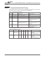
1
Powered by Eaton’s
Cutler-Hammer Technology
N2 and MODBUS Communication Kit
User Manual
November 2004
Supersedes August 2004
VS IntelliPass Bypass
LIT-1201829
VS Open
For more information visit: www.johnsoncontrols.com
Powered by Eaton’s
Cutler-Hammer Technology
N2 and MODBUS Communication Kit User Manual
November 2004
Important Notice – Please Read
The product discussed in this literature is subject to terms and conditions outlined in
Johnson Controls selling policies. The sole source governing the rights and remedies of any
purchaser of this equipment is the relevant Johnson Controls selling policy.
NO WARRANTIES, EXPRESS OR IMPLIED, INCLUDING WARRANTIES OF FITNESS FOR A
PARTICULAR PURPOSE OR MERCHANTABILITY, OR WARRANTIES ARISING FROM COURSE
OF DEALING OR USAGE OF TRADE, ARE MADE REGARDING THE INFORMATION,
RECOMMENDATIONS AND DESCRIPTIONS CONTAINED HEREIN. In no event will Johnson
Controls or Eaton Electrical Inc. be responsible to the purchaser or user in contract, in tort
(including negligence), strict liability or otherwise for any special, indirect, incidental or
consequential damage or loss whatsoever, including but not limited to damage or loss of use of
equipment, plant or power system, cost of capital, loss of power, additional expenses in the use
of existing power facilities, or claims against the purchaser or user by its customers resulting
from the use of the information, recommendations and descriptions contained herein.
The information contained in this manual is subject to change without notice.
Cover Photo: Johnson Controls VS Series Drives.
LIT-1201829
For more information visit: www.johnsoncontrols.com
i
N2 and MODBUS Communication Kit User Manual
Powered by Eaton’s
Cutler-Hammer Technology
November 2004
Table of Contents
LIST OF FIGURES . . . . . . . . . . . . . . . . . . . . . . . . . . . . . . . . . . . . . . . . . . . . . . . . . . . . . . .
LIST OF TABLES . . . . . . . . . . . . . . . . . . . . . . . . . . . . . . . . . . . . . . . . . . . . . . . . . . . . . . . .
SAFETY . . . . . . . . . . . . . . . . . . . . . . . . . . . . . . . . . . . . . . . . . . . . . . . . . . . . . . . . . . . . . . .
Definitions and Symbols . . . . . . . . . . . . . . . . . . . . . . . . . . . . . . . . . . . . . . . . . . . . .
Hazardous High Voltage . . . . . . . . . . . . . . . . . . . . . . . . . . . . . . . . . . . . . . . . . . . . .
iii
iii
iv
iv
iv
CHAPTER 1 — OVERVIEW . . . . . . . . . . . . . . . . . . . . . . . . . . . . . . . . . . . . . . . . . . . . . . . 1-1
Introduction . . . . . . . . . . . . . . . . . . . . . . . . . . . . . . . . . . . . . . . . . . . . . . . . . . . . . . . 1-1
Specifications . . . . . . . . . . . . . . . . . . . . . . . . . . . . . . . . . . . . . . . . . . . . . . . . . . . . . . 1-1
CHAPTER 2 — BOARD LAYOUT AND CONNECTIONS . . . . . . . . . . . . . . . . . . . . . . . . 2-1
OPTC2 Communication Board . . . . . . . . . . . . . . . . . . . . . . . . . . . . . . . . . . . . . . . . 2-1
OPTC8 Communication Board with D-Sub Connector . . . . . . . . . . . . . . . . . . . . . 2-2
CHAPTER 3 — INSTALLATION . . . . . . . . . . . . . . . . . . . . . . . . . . . . . . . . . . . . . . . . . . . .
Making the Ground Connection . . . . . . . . . . . . . . . . . . . . . . . . . . . . . . . . . . . . . . .
Bus Terminal Resistors . . . . . . . . . . . . . . . . . . . . . . . . . . . . . . . . . . . . . . . . . . . . . .
Bus Biasing . . . . . . . . . . . . . . . . . . . . . . . . . . . . . . . . . . . . . . . . . . . . . . . . . . . . . . . .
LED Indications. . . . . . . . . . . . . . . . . . . . . . . . . . . . . . . . . . . . . . . . . . . . . . . . . . . . .
Installing the C2 Communication Board . . . . . . . . . . . . . . . . . . . . . . . . . . . . . . . .
3-1
3-1
3-3
3-4
3-6
3-7
CHAPTER 4 — COMMISSIONING . . . . . . . . . . . . . . . . . . . . . . . . . . . . . . . . . . . . . . . . . . 4-1
Fieldbus Board Parameters . . . . . . . . . . . . . . . . . . . . . . . . . . . . . . . . . . . . . . . . . . . 4-1
RS-485 Communication Parameters. . . . . . . . . . . . . . . . . . . . . . . . . . . . . . . . . . . . 4-1
CHAPTER 5 — JOHNSON CONTROLS METASYS N2 PROTOCOL . . . . . . . . . . . . . . . 5-1
Overview . . . . . . . . . . . . . . . . . . . . . . . . . . . . . . . . . . . . . . . . . . . . . . . . . . . . . . . . . . 5-1
N2 Point Map . . . . . . . . . . . . . . . . . . . . . . . . . . . . . . . . . . . . . . . . . . . . . . . . . . . . . . 5-3
ii
CHAPTER 6 — MODBUS . . . . . . . . . . . . . . . . . . . . . . . . . . . . . . . . . . . . . . . . . . . . . . . . .
MODBUS RTU Protocol . . . . . . . . . . . . . . . . . . . . . . . . . . . . . . . . . . . . . . . . . . . . . .
Supported Functions . . . . . . . . . . . . . . . . . . . . . . . . . . . . . . . . . . . . . . . . . . . . . . . .
Exception Responses . . . . . . . . . . . . . . . . . . . . . . . . . . . . . . . . . . . . . . . . . . . . . . . .
MODBUS Interface . . . . . . . . . . . . . . . . . . . . . . . . . . . . . . . . . . . . . . . . . . . . . . . . . .
Start-Up Test . . . . . . . . . . . . . . . . . . . . . . . . . . . . . . . . . . . . . . . . . . . . . . . . . . . . . . .
6-1
6-1
6-2
6-4
6-6
6-13
CHAPTER 7 — COMMUNICATION BOARD FAULT TRACKING . . . . . . . . . . . . . . . . . .
APPENDIX A — PROCESS DATA . . . . . . . . . . . . . . . . . . . . . . . . . . . . . . . . . . . . . . . . . .
Process Data OUT (Slave ➔ Master) . . . . . . . . . . . . . . . . . . . . . . . . . . . . . . . . . . .
Process Data IN (Master ➔ Slave) . . . . . . . . . . . . . . . . . . . . . . . . . . . . . . . . . . . . .
7-1
A-1
A-1
A-1
For more information visit: www.johnsoncontrols.com
LIT-1201829
Powered by Eaton’s
Cutler-Hammer Technology
N2 and MODBUS Communication Kit User Manual
November 2004
List of Figures
Figure 2-1: Option Board OPTC2 Communication Board . . . . . . . . . . . . . . . . . . . . . . . . .
Figure 2-2: Option Board OPTC8 Communication Board with D-Sub Connector . . . . . .
Figure 3-1: Cable Stripping . . . . . . . . . . . . . . . . . . . . . . . . . . . . . . . . . . . . . . . . . . . . . . . . . .
Figure 3-2: Inserting the Data Cables . . . . . . . . . . . . . . . . . . . . . . . . . . . . . . . . . . . . . . . . .
Figure 3-3: Grounding the Communication Cable . . . . . . . . . . . . . . . . . . . . . . . . . . . . . . .
Figure 3-4: Stripping the Communication Cables . . . . . . . . . . . . . . . . . . . . . . . . . . . . . . .
Figure 3-5: Grounding the Communication Cable . . . . . . . . . . . . . . . . . . . . . . . . . . . . . . .
Figure 3-6: Using Jumper X4 to Set the Bus Termination . . . . . . . . . . . . . . . . . . . . . . . . .
Figure 3-7: Grounding Jumper X1 . . . . . . . . . . . . . . . . . . . . . . . . . . . . . . . . . . . . . . . . . . . .
Figure 3-8: Connecting Resistor Biasing . . . . . . . . . . . . . . . . . . . . . . . . . . . . . . . . . . . . . . .
Figure 3-9: LED Indications on the Communication Board . . . . . . . . . . . . . . . . . . . . . . . .
Figure 4-1: Communication Status . . . . . . . . . . . . . . . . . . . . . . . . . . . . . . . . . . . . . . . . . . .
Figure 6-1: The Basic Structure of a Modbus Frame . . . . . . . . . . . . . . . . . . . . . . . . . . . . .
2-1
2-2
3-1
3-1
3-2
3-2
3-3
3-3
3-4
3-5
3-6
4-2
6-1
List of Tables
Table 1-1: Specifications . . . . . . . . . . . . . . . . . . . . . . . . . . . . . . . . . . . . . . . . . . . . . . . . . . . .
Table 2-1: OPTC2 Bus Connector Signals . . . . . . . . . . . . . . . . . . . . . . . . . . . . . . . . . . . . . .
Table 2-2: OPTC8 Bus Connector Signals . . . . . . . . . . . . . . . . . . . . . . . . . . . . . . . . . . . . . .
Table 3-1: Bias Resistor Size vs. Number of Nodes. . . . . . . . . . . . . . . . . . . . . . . . . . . . . . .
Table 3-2: Communication Board Status LED (BS) — YELLOW . . . . . . . . . . . . . . . . . . . .
Table 3-3: Fieldbus Status LED (FS) — GREEN . . . . . . . . . . . . . . . . . . . . . . . . . . . . . . . . . .
Table 3-4: Installing the C2 Communication Board . . . . . . . . . . . . . . . . . . . . . . . . . . . . . .
Table 4-1: Changing the Modbus Board Commissioning Parameter Values . . . . . . . . . .
Table 4-2: Communication Message Indications . . . . . . . . . . . . . . . . . . . . . . . . . . . . . . . .
Table 5-1: Analog Inputs (AI) . . . . . . . . . . . . . . . . . . . . . . . . . . . . . . . . . . . . . . . . . . . . . . . .
Table 5-2: Binary Inputs (BI) . . . . . . . . . . . . . . . . . . . . . . . . . . . . . . . . . . . . . . . . . . . . . . . . .
Table 5-3: Analog Outputs (AO) . . . . . . . . . . . . . . . . . . . . . . . . . . . . . . . . . . . . . . . . . . . . . .
Table 5-4: Binary Outputs (BO) . . . . . . . . . . . . . . . . . . . . . . . . . . . . . . . . . . . . . . . . . . . . . . .
Table 5-5: Internal Integers (ADI) . . . . . . . . . . . . . . . . . . . . . . . . . . . . . . . . . . . . . . . . . . . . .
Table 6-1: Supported Messages . . . . . . . . . . . . . . . . . . . . . . . . . . . . . . . . . . . . . . . . . . . . . .
Table 6-2: Exception Response Codes . . . . . . . . . . . . . . . . . . . . . . . . . . . . . . . . . . . . . . . . .
Table 6-3: Index Table . . . . . . . . . . . . . . . . . . . . . . . . . . . . . . . . . . . . . . . . . . . . . . . . . . . . . .
Table 6-4: Process Data Slave ➔ Master — (max. 22 bytes) . . . . . . . . . . . . . . . . . . . . . . .
Table 6-5: Process Data Master ➔ Slave — (max. 22 bytes) . . . . . . . . . . . . . . . . . . . . . . .
Table 6-6: Fieldbus Basic Input Table . . . . . . . . . . . . . . . . . . . . . . . . . . . . . . . . . . . . . . . . . .
Table 6-7: Control Word Bit Descriptions . . . . . . . . . . . . . . . . . . . . . . . . . . . . . . . . . . . . . .
Table 6-8: Fieldbus Basic Output Table . . . . . . . . . . . . . . . . . . . . . . . . . . . . . . . . . . . . . . . .
Table 6-9: Status Word Bit Descriptions . . . . . . . . . . . . . . . . . . . . . . . . . . . . . . . . . . . . . . .
Table 6-10: Parameters . . . . . . . . . . . . . . . . . . . . . . . . . . . . . . . . . . . . . . . . . . . . . . . . . . . . .
Table 6-11: Actual Values . . . . . . . . . . . . . . . . . . . . . . . . . . . . . . . . . . . . . . . . . . . . . . . . . . .
Table 7-1: Communication Board Faults . . . . . . . . . . . . . . . . . . . . . . . . . . . . . . . . . . . . . . .
Table 7-2: AFD Response to Faults . . . . . . . . . . . . . . . . . . . . . . . . . . . . . . . . . . . . . . . . . . .
Table A-1: Process Data OUT . . . . . . . . . . . . . . . . . . . . . . . . . . . . . . . . . . . . . . . . . . . . . . . .
Table A-2: Process Data IN — VS Series Applications . . . . . . . . . . . . . . . . . . . . . . . . . . . .
LIT-1201829
For more information visit: www.johnsoncontrols.com
1-1
2-1
2-2
3-4
3-6
3-6
3-7
4-1
4-2
5-3
5-4
5-4
5-5
5-5
6-2
6-4
6-6
6-6
6-7
6-7
6-8
6-9
6-9
6-10
6-10
7-1
7-1
A-1
A-1
iii
N2 and MODBUS Communication Kit User Manual
Powered by Eaton’s
Cutler-Hammer Technology
November 2004
Safety
Definitions and Symbols
WARNING
This symbol indicates high voltage. It calls your attention to items
or operations that could be dangerous to you and other persons
operating this equipment. Read the message and follow the
instructions carefully.
This symbol is the “Safety Alert Symbol.” It occurs with either of
two signal words: CAUTION or WARNING, as described below.
WARNING
Indicates a potentially hazardous situation which, if not avoided,
can result in serious injury or death.
CAUTION
Indicates a potentially hazardous situation which, if not avoided,
can result in minor to moderate injury, or serious damage to the
product. The situation described in the CAUTION may, if not
avoided, lead to serious results. Important safety measures are
described in CAUTION (as well as WARNING).
Hazardous High Voltage
WARNING
Motor control equipment and electronic controllers are connected
to hazardous line voltages. When servicing drives and electronic
controllers, there may be exposed components with housings or
protrusions at or above line potential. Extreme care should be taken
to protect against shock.
Stand on an insulating pad and make it a habit to use only one
hand when checking components. Always work with another
person in case an emergency occurs. Disconnect power before
checking controllers or performing maintenance. Be sure
equipment is properly grounded. Wear safety glasses whenever
working on electronic controllers or rotating machinery.
iv
For more information visit: www.johnsoncontrols.com
LIT-1201829
Powered by Eaton’s
Cutler-Hammer Technology
N2 and MODBUS Communication Kit User Manual
November 2004
Chapter 1 — Overview
Introduction
The Johnson Controls VS Series Drives powered by Cutler-Hammer® technology from
Eaton’s electrical business can be controlled, monitored and programmed from a host
system via Johnson Controls N2 or MODBUS RTU communication protocols with the
addition of the OPTC2 RS-485 Communication Option Board kit.
If you purchase your Communication Board Kit separate from the drive, please note that it
must be installed in slot E on the control board of the VS Series drive.
Specifications
Table 1-1: Specifications
Item
Specification
Communication Board Connections
Interface
OPTC2: Pluggable connector (5.08 mm)
OPTC8: 9-pin DSUB connector (female)
Data Transfer Method
RS-485, half-duplex
Transfer Cable
Twisted pair (1 pair and shield)
Electrical Isolation
500V DC
Communications
Johnson Controls N2
As described in Metasys N2 System Protocol Specification
Modbus RTU
As described in “Modicon Modbus Protocol Reference Guide”
found at: http://public.modicon.com/
Baud Rate
300, 600, 1200, 2400, 4800, 9600, 19200 and 38400 Kbaud
Addresses
1 to 247
Environment
Ambient Operating Temperature
14 to 131°F (-10 to 55°C)
Storage Temperature
-40 to 140°F (-40 to 60°C)
Humidity
<95%, non-condensing
Altitude
Max. 3280 ft. (1000m)
Vibration
0.5G at 9 to 200 Hz
Safety
LIT-1201829
Standards
Fulfils EN 50178 standard
Certification
CE, UL
For more information visit: www.johnsoncontrols.com
1-1
N2 and MODBUS Communication Kit User Manual
Powered by Eaton’s
Cutler-Hammer Technology
November 2004
1-2
For more information visit: www.johnsoncontrols.com
LIT-1201829
Powered by Eaton’s
Cutler-Hammer Technology
N2 and MODBUS Communication Kit User Manual
November 2004
Chapter 2 — Board Layout and Connections
The RS-485 Communication Board is connected to the communications bus through either a
5-pin pluggable bus connector (board OPTC2) or a 9-pin female D-sub connector (board
OPTC8).
Communication with the control board of the drive takes place through the standard Interface
Board Connector (see Figures 2-1 and 2-2).
OPTC2 Communication Board
Yellow = RS-485 Board Status
Green = Field Bus Status
1
2
3
4
5
X4
X1
Bus Connector
Jumpers
Interface Board Connector
Figure 2-1: Option Board OPTC2 Communication Board
Table 2-1: OPTC2 Bus Connector Signals
Signal
Connector
Description
NC 1
No connection
VP
2
Supply voltage – plus (5V)
RxD/TxD –N
3
Receive/Transmit data – minus (A)
RxD/TxD –P
4
Receive/Transmit data – plus (B)
DGND
5
Data ground (reference potential for VP)
This pin (1) can be used to bypass the cable shield to the next slave.
X4 jumper is the 120Ω termination resistor. Set X4 jumper to ON only if the
Johnson Controls drive is the last device on the network.
ON
X1 jumper has no effect on OPTC2 board. It is used on the OPTC8 board on the
following page.
OFF
LIT-1201829
For more information visit: www.johnsoncontrols.com
2-1
N2 and MODBUS Communication Kit User Manual
Powered by Eaton’s
Cutler-Hammer Technology
November 2004
OPTC8 Communication Board with D-Sub Connector
5
4
9
3
8
2
7
1
6
X4
X1
Bus Connector
Jumpers
Interface Board Connector
Figure 2-2: Option Board OPTC8 Communication Board with D-Sub Connector
Table 2-2: OPTC8 Bus Connector Signals
Signal
Connector
Description
Shield
1
Cable shield
RxD/TxD –N
3
Receive/Transmit data – minus (A)
DGND
5
Data ground (reference potential for VP)
VP
6
Supply voltage – (+5V)
RxD/TxD –P
8
Receive/Transmit data – plus (B)
X4 jumper is the 120Ω termination resistor. Set X4 jumper to ON only if the
Johnson Controls drive is the last device on the network.
ON
OFF
2-2
X1 jumper is used for grounding selection on the OPTC8 board only. ON position
means that D-sub connector PIN 1 is connected directly to ground. OFF position
means that PIN 1 is connected via RC filter to ground.
For more information visit: www.johnsoncontrols.com
LIT-1201829
Powered by Eaton’s
Cutler-Hammer Technology
N2 and MODBUS Communication Kit User Manual
November 2004
Chapter 3 — Installation
Making the Ground Connection
Grounding by Clamping the Cable to the Converter Frame
This method of grounding is the most effective, and especially recommended when the
distances between the devices are relatively short or if the device is the last device on the
network.
Note: Normally, the option board has already been installed in slot E of the control board. It is
not necessary to detach the whole board to ground the bus cable shield. Just detach
the terminal block.
1. Strip about 2 in. (5 cm) of the communication cable and cut off the gray cable shield.
Remember to do this for both bus cables (except for the last device). See Figure 3-1.
2. Leave no more than 1/4 in. (1 cm) of the cable outside the terminal block and strip the
data cables at about 0.2 in (0.5 cm) to fit in the terminals. See Figure 3-1. Note: Do this
for both bus cables.
Figure 3-1: Cable Stripping
3. Insert the data cables into terminals #3 (Line A) and #4 (Line B).
1 2 3 4 5
A
B
Figure 3-2: Inserting the Data Cables
LIT-1201829
For more information visit: www.johnsoncontrols.com
3-1
N2 and MODBUS Communication Kit User Manual
Powered by Eaton’s
Cutler-Hammer Technology
November 2004
4. Strip the communication cable so that it can be secured to the drive frame with the
grounding clamp.
Figure 3-3: Grounding the Communication Cable
Grounding Only One Point on the Net
In this method of grounding, the shield is connected to ground only at the last device on the
network. Other devices on the network just bypass the shield.
We recommend you to use an Abico connector to fit the shields into the terminal.
1. Strip about 2 in. (5 cm) of the communication cable and cut off the gray cable shield.
Remember to do this for both bus cables (except for the last device).
2. Leave no more than 1/4 in. (1 cm) of the cable outside the terminal block and strip the
data cables at about 0.5 cm to fit in the terminals. See Figure 3-4. Note: Do this for both
bus cables.
1 2 3 4 5
Shield
A
B
Figure 3-4: Stripping the Communication Cables
3-2
For more information visit: www.johnsoncontrols.com
LIT-1201829
Powered by Eaton’s
Cutler-Hammer Technology
N2 and MODBUS Communication Kit User Manual
November 2004
3. Secure the communication cable to the drive frame with the grounding clamp as shown
in Figure 3-5.
Figure 3-5: Grounding the Communication Cable
Bus Terminal Resistors
If the C2 or C8 Option Card is the last device on the network, the bus termination must be set
to ON. Use jumper X4 (set to the ON position for termination). See Figure 3-6.
ON = Terminated: This is the last device on network.
OFF = Not Terminated: At least one other network
device is connected past this device.
1
2
3
4
5
X4
X1
Bus Connector
Jumpers
Interface Board Connector
Figure 3-6: Using Jumper X4 to Set the Bus Termination
LIT-1201829
For more information visit: www.johnsoncontrols.com
3-3
N2 and MODBUS Communication Kit User Manual
Powered by Eaton’s
Cutler-Hammer Technology
November 2004
Grounding Jumper X1
The grounding jumper X1 on the OPTC8 is used for grounding selection. If position ON is
selected it means that the D-sub connector PIN1 is connected directly to ground. Selection of
position OFF means that PIN1 is connected to ground via an RC-filter. Jumper X1 has no
effect on OPTC2. See Figure 3-7.
5
4
9
3
8
2
7
1
6
ON
OFF
X4
X1
Jumpers
Figure 3-7: Grounding Jumper X1
Bus Biasing
Bus biasing is required to ensure faultless communication between devices at RS-485 bus.
Bus biasing makes sure that the bus state has proper potential when no one is transmitting.
Without biasing faulty messages can be detected when the bus is in idle state. RS-485 bus
state should be from +0.200 to +7V or -0.200 to -7V. Illegal bus state is from -0.200 to 0.200V.
Table 3-1: Bias Resistor Size vs. Number of Nodes
3-4
Number of Nodes
Bias Resistance
2–5
5 – 10
11 – 20
21 – 30
31 – 40
1.8k ohm
2.7k ohm
12k ohm
18k ohm
27k ohm
For more information visit: www.johnsoncontrols.com
LIT-1201829
Powered by Eaton’s
Cutler-Hammer Technology
N2 and MODBUS Communication Kit User Manual
November 2004
Failsafe Biasing in OPTC2 Option Board
Connect resistor biasing resistors between PIN 2 – PIN 4 and PIN 3 – PIN 5. See Figure 3-8.
DataData+
Figure 3-8: Connecting Resistor Biasing
National Semiconductor (www.national.com) has a very good application note concerning
this problem. It is Failsafe Biasing of Differential Buses (AN-847.PDF).
LIT-1201829
For more information visit: www.johnsoncontrols.com
3-5
N2 and MODBUS Communication Kit User Manual
Powered by Eaton’s
Cutler-Hammer Technology
November 2004
LED Indications
The two LED indicators next to the connector show the present status of the Communication
Board (yellow) and the Fieldbus Module (green).
Yellow = RS-485 Board Status
Green = Fieldbus Status
Yellow
Green
1
2
3
4
5
X4
X1
Figure 3-9: LED Indications on the Communication Board
Table 3-2: Communication Board Status LED (BS) — YELLOW
LED is:
Meaning:
OFF
Option board not activated
ON
Option board in initialization state waiting for activation command from
the Adjustable Frequency Drive (AFD)
Blinking fast (once/sec)
Option board is activated and in RUN state
Option board is ready for external communication
Blinking slow (once/5 secs)
Option board is activated and in FAULT state
Internal fault of option board
Table 3-3: Fieldbus Status LED (FS) — GREEN
3-6
LED is:
Meaning:
OFF
Fieldbus module is waiting for parameters from the AFD
No external communication
ON
Fieldbus module is activated
Parameters received and module activated
Module is waiting for messages from the bus
Blinking fast (once/sec)
Module is activated and receiving messages from the bus
Blinking slow (once/5 secs)
Module is in FAULT state
No messages from Master within the watchdog time
Bus broken, cable loose or Master off-line
For more information visit: www.johnsoncontrols.com
LIT-1201829
Powered by Eaton’s
Cutler-Hammer Technology
N2 and MODBUS Communication Kit User Manual
November 2004
Installing the C2 Communication Board
Table 3-4: Installing the C2 Communication Board
Procedure
Illustration
1. Remove the cable cover.
2. Open the cover of the control unit.
3. Install the C2 option board in slot E on the control board of
the AFD. Make sure that the grounding plate (see below)
fits tightly in the clamp.
1
2
3
4
5
X4
X1
Grounding Plate
LIT-1201829
For more information visit: www.johnsoncontrols.com
3-7
N2 and MODBUS Communication Kit User Manual
Powered by Eaton’s
Cutler-Hammer Technology
November 2004
Table 3-4: Installing the C2 Communication Board, continued
Procedure
Illustration
4. Make a sufficiently wide opening for your cable by cutting
the cover grid as wide as necessary.
5. Close the cover of the control unit and the cable cover.
3-8
For more information visit: www.johnsoncontrols.com
LIT-1201829
Powered by Eaton’s
Cutler-Hammer Technology
N2 and MODBUS Communication Kit User Manual
November 2004
Chapter 4 — Commissioning
Fieldbus Board Parameters
The RS-485 Communication boards (OPTC2 and OPTC8) are commissioned with the control
keypad by giving values to appropriate parameters in the Expander board menu M6.
Expander Board Menu (M5)
The Expander board menu makes it possible for the user, (1) to see what expander boards
are connected to the control board and (2) to view and edit the parameters associated with
the expander board.
Enter the following menu level (G#) with the menu button Right. At this level, you can browse
through slots A to E with the Browser buttons to see which expander boards are installed. On
the bottom line of the display, you also see the number of parameter groups associated with
the board.
If you still press the menu button Right once you will reach the parameter group level where
there are two groups: Editable parameters and Monitored values. A further press on the
menu button Right takes you to either of these groups.
RS-485 Communication Parameters
To commission the RS-485 communication board, enter the level P6.4.1.1 from the
Parameters group (G6.4.1).
Table 4-1: Changing the Modbus Board Commissioning Parameter Values
#
Name
Default
Range
Description
1
Communication
Protocol
2
1 – Modbus RTU
2 – N2
2
Slave Address
1
1…247
3
BAUD Rate
6
1 – 300 baud
2 – 600 baud
3 – 1200 baud
4 – 2400 baud
5 – 4800 baud
6 – 9600 baud
7 – 19200 baud
8 – 38400 baud
Communication speed
Note: When the N2 protocol is used, the
Baud Rate Setting must be: 6 – 9600 baud
4
Parity Type
0
0 – None
1 – Even
2 – Odd
Describes what kind of parity checking is
used.
5
Communication
Timeout
10
0 – OFF
1 – 300 s
See Communication Timeout on Page 4-2
6
Operate Mode
1
1 – Normal
Reserved for later use
The parameters of every device must be set before connecting to the bus. Especially the
parameters “SLAVE ADDRESS” and “BAUD RATE” must be the same as in the master
configuration.
LIT-1201829
For more information visit: www.johnsoncontrols.com
4-1
N2 and MODBUS Communication Kit User Manual
Powered by Eaton’s
Cutler-Hammer Technology
November 2004
Communication Timeout
The RS-485 communication board initiates a communication error if communication is
broken for as long as defined by Communication Timeout. Communication Timeout is
disabled when given the value 0.
Communication Status
To see the present status of the communication board, enter the Communication status page
from the Monitor menu (G6.4.2). See Figure 4-1 and Table 4-2.
Monitor
Comm. status
V1
V1
0.841
Good Message
Error Message
Figure 4-1: Communication Status
Table 4-2: Communication Message Indications
Messages
Indications
Good messages
0 – 999
Number of messages received without communication errors
Error messages
0 – 64
4-2
Number of messages received with CRC or parity errors
For more information visit: www.johnsoncontrols.com
LIT-1201829
Powered by Eaton’s
Cutler-Hammer Technology
N2 and MODBUS Communication Kit User Manual
November 2004
Chapter 5 — Johnson Controls Metasys N2 Protocol
Overview
The N2 Interface provides:
●
Direct control of Drive (e.g. Run, Stop, Direction, Speed reference, Fault reset)
●
Full access to necessary parameters
●
Monitoring of Drive status (e.g. Output frequency, Output current, Fault code)
●
In stand-alone operation, or if the polling is stopped, the overridden values are released
after a specified period (about 10 minutes).
Analog Input (AI) Features
All Analog Input (AI) points have the following features:
●
Support Change of State (COS) reporting based on high and low warning limits.
●
Support Change of State (COS) reporting based on high and low alarm limits.
●
Support Change of State (COS) reporting based on override status.
●
Always considered reliable and never out of range.
●
Writing of alarm and warning limit values beyond the range that can be held by the
drive’s internal variable will result in having that limit replaced by the “Invalid Float”
value even though the message is acknowledged. The net result will be the inactivation
of the alarm or warning (the same as if the original out of range value was used).
●
Overriding is supported from the standpoint that the “Override Active” bit will be set
and the value reported to the N2 network will be the overridden value. However, the
value in the drive remains unchanged. Therefore, the N2 system should be set up to
disallow overriding AI points or have an alarm condition activated when a AI point is
overridden.
●
Overriding an AI point with a value beyond the limit allowed by the drive’s internal
variable will result in an “Invalid Data” error response and the override status and
value will remain unchanged.
Binary Input (BI) Features
All Binary Input (BI) points have the following features:
●
Support Change of State (COS) reporting based on current state.
●
Support Change of State (COS) reporting based on alarm condition.
●
Support Change of State (COS) reporting based on override status.
●
Always considered reliable.
Overriding is supported from the standpoint that the “Override Active” bit will be set and the
value reported to the N2 network will be the overridden value. However, the value in the
drive remains unchanged. Therefore, the N2 system should be set up to disallow overriding
BI points or have an alarm condition activated when a BI point is overridden.
LIT-1201829
For more information visit: www.johnsoncontrols.com
5-1
N2 and MODBUS Communication Kit User Manual
Powered by Eaton’s
Cutler-Hammer Technology
November 2004
Analog Output (AO) Features
All Analog Output (AO) points have the following features:
●
Support Change of State (COS) reporting based on override status.
●
Always considered reliable.
●
Overriding of the AO points is the method used to change a value. Overriding an AO
point with a value beyond the limit allowed by the drive’s internal variable will result in
an “Invalid Data” error response and the override status and value will remain
unchanged. If the overridden value is beyond the drive’s parameter limit but within the
range that will fit in the variable, an acknowledge response is given and the value will
be internally clamped to its limit.
●
An AO point override copies the override value to the corresponding drive parameter.
This is the same as changing the value on the keypad. The value is nonvolatile and will
remain in effect when the drive is turned off and back on. It also remains at this value
when the N2 network “Releases” the point. The N2 system always reads the current
parameter value.
Note: On some N2 systems, the system will not poll the AO point when it is being overridden.
In this case, the N2 system will not notice a change in value if the change is made via
the keypad. To avoid this scenario, set the point up as a “local control” type and
release it once it has been overridden. In this way, the N2 system will monitor the value
when not being overridden.
Binary Output (BO) Features
All Binary Output (BO) points have the following features:
●
Support Change of State (COS) reporting based on override status.
●
Always considered reliable.
●
Overriding BO points control the drive. These points are inputs commands to the drive.
When released, the drive’s internal value remains at its last overridden value.
Internal Integer (ADI) Features
All Internal Integer (ADI) points have the following features:
5-2
●
Do not support Change of State (COS) reporting.
●
Can be overridden and the “Override Active” bit will be set. However, the Internal value
is unchanged (Read Only).
For more information visit: www.johnsoncontrols.com
LIT-1201829
Powered by Eaton’s
Cutler-Hammer Technology
N2 and MODBUS Communication Kit User Manual
November 2004
N2 Point Map
Analog Input (AI) Point Map
Table 5-1: Analog Inputs (AI)
NPT
NPA
Description
Units
Note
AI
1
Speed Setpoint
Hz
2 decimals
AI
2
Output Speed
Hz
2 decimals
AI
3
Motor Speed
Rpm
0 decimal
AI
4
Load (power)
%
1 decimal
AI
5
Megawatt Hours
MWh
Total Counter
AI
6
Motor Current
A
2 decimal
AI
7
Bus Voltage
V
0 decimal
AI
8
Motor Volts
V
1 decimal
AI
9
Heatsink Temperature
°C
0 decimal
AI
10
Motor Torque
%
1 decimal
AI
11
Operating Days
Day
0 decimal
AI
12
Operating Hours
Hour
0 decimal
AI
13
Kilowatt Hours
kWh
Trip Counter
AI
14
Torque Reference
%
1 decimal
AI
15
Motor Temperature Rise
AI
1 decimal
FBProcessDataOUT1
—
0 decimal
AI
17
FBProcessDataOUT2
—
0 decimal
AI
18
FBProcessDataOUT3 —
0 decimal
19
FBProcessDataOUT4
—
0 decimal
FBProcessDataOUT5
—
0 decimal
AI
AI
20
AI
21
FBProcessDataOUT6
—
0 decimal
AI
22
FBProcessDataOUT7 —
0 decimal
23
—
0 decimal
AI
LIT-1201829
16
%
FBProcessDataOUT8
These analog inputs are application specific. See Table A-1 on Page A-1.
For more information visit: www.johnsoncontrols.com
5-3
N2 and MODBUS Communication Kit User Manual
Powered by Eaton’s
Cutler-Hammer Technology
November 2004
Binary Input (BI) Point Map
Table 5-2: Binary Inputs (BI)
NPT
NPA
Description
0=
1=
BI
1
Ready
Not Ready
Ready
BI
2
Run
Stop
Run
BI
3
Direction
Clockwise
Counterclockwise
BI
4
Faulted
Not Faulted
Faulted
BI
5
Warning
Not Warning
Warning
BI
6
Ref. Frequency reached
False
True
BI
7
Motor running at zero speed
False
True
BI
8
Digital Input Interlock
False
True
BI
9
Bypass Mode Active
False
True
BI
10
Digital Input Fire Mode
False
True
BI
11
Hand Control Mode
False
True
BI
12
Auto Control Mode
False
True
BI
13
Control Mode OFF
False
True
Analog Output (AO) Point Map
Table 5-3: Analog Outputs (AO)
NPT
NPA
Description
Units
Note
AO
1
Comms Speed
%
2 decimal
AO
2
Current Limit
A
2 decimal
AO
3
Minimum Speed
Hz
2 decimal
AO
4
Maximum Speed
Hz
2 decimal
AO
5
Accel Time
s
1 decimal
AO
6
Decel Time
s
1 decimal
%
2 decimal
%
2 decimal
AO
AO
5-4
7
8
FB PI Setpoint
FB Actual Value
These analog outputs are sent to the drive and require Parameter 1.1.15 St Pt source auto to be set to “Fieldbus” for AO-7 and
Parameter 1.1.17 PI-Input source to be set to “Fieldbus” for AO-8.
For more information visit: www.johnsoncontrols.com
LIT-1201829
Powered by Eaton’s
Cutler-Hammer Technology
N2 and MODBUS Communication Kit User Manual
November 2004
Binary Output (BO) Point Map
Table 5-4: Binary Outputs (BO)
NPT
NPA
Description
0=
1=
BO
1
Comms Start/Stop
Stop
Start
BO
2
Comms Forward/Reverse
Forward
Reverse
BO
3
Comms Reset Fault
N/A
Reset
BO
4
Enable Bypass
FB FixedControlWord Bit_3 Disable
Enable
BO
5
Activate FB.DI-3
FBFixedControlWord Bit_4 OFF
ON
BO
6
Activate FB.DI-4
FBFixedControlWord Bit_5 OFF
ON
BO
7
Activate FB.DI-5
FBFixedControlWord Bit_6 OFF
ON
BO
8
Activate FB.DI-6
FBFixedControlWord Bit_7 OFF
ON
BO
11
Pass Through RO-1
OFF
ON
BO
12
Pass Through RO-2
OFF
ON
BO
13
Pass Through DO-1
OFF
ON
BO
14
Activate Fire Mode
OFF
ON
BO
15
Comms PM Setback
OFF
ON
These binary outputs are application specific. These can be used to override DI-2 through DI-6 to the “ON” or “Activated” position.
Pass Through Digital and Relay Outputs
If controlling digital or relay outputs through the fieldbus, set parameters P1.3.6 – P1.3.8 “Not
Used” (#0).
Internal Integer (ADI) Point Mapping
Table 5-5: Internal Integers (ADI)
LIT-1201829
NPT
NPA
ADI
1
Description
Units
Active Fault Code
—
For more information visit: www.johnsoncontrols.com
5-5
N2 and MODBUS Communication Kit User Manual
Powered by Eaton’s
Cutler-Hammer Technology
November 2004
5-6
For more information visit: www.johnsoncontrols.com
LIT-1201829
Powered by Eaton’s
Cutler-Hammer Technology
N2 and MODBUS Communication Kit User Manual
November 2004
Chapter 6 — Modbus
MODBUS RTU Protocol
The MODBUS protocol is an industrial communications and distributed control system to
integrate PLCs, computers, terminals, and other monitoring, sensing and control devices.
MODBUS is a Master-Slave communications protocol. The Master controls all serial activity
by selectively polling one or more slave devices. The protocol provides for one master device
and up to 247 slave devices on a common line. Each device is assigned an address to
distinguish it from all other connected devices.
The MODBUS protocol uses the master-slave technique, in which only one device (the
master) can initiate a transaction. The other devices (the slaves) respond by supplying the
requested data to the master, or by taking the action requested in the query. The master can
address individual slaves or initiate a broadcast message to all slaves. Slaves return a
message (“response”) to queries that are addressed to them individually. Responses are not
returned to broadcast queries from the master.
A transaction comprises a single query and single response frame or a single broadcast
frame. The transaction frames are defined below.
Master’s
Message
Slave’s
Response
Start
Address
Function
Data
Start
Address
Function
Data
CRC
End
CRC
End
Figure 6-1: The Basic Structure of a Modbus Frame
Valid slave device addresses are in the range of 0 – 247 decimal. The individual slave devices
are assigned addresses in the range of 1 – 247. A master addresses a slave by placing the
slave address in the address field of the message. When the slave sends its response, it
places its own address in this address field of the response to let the master know which
slave is responding.
The function code field of a message frame contains two characters (ASCII) or eight bits
(RTU). Valid codes are in the range of 1 – 255 decimal. When a message is sent from a master
to a slave device, the function code field tells the slave what kind of action to perform.
Examples are to read the ON/OFF states of a group of discrete coils or inputs; to read the data
contents of a group of registers; to read the diagnostic status of the slave; to write to
designated coils or registers; or to allow loading, recording or verifying the program within
the slave.
LIT-1201829
For more information visit: www.johnsoncontrols.com
6-1
N2 and MODBUS Communication Kit User Manual
Powered by Eaton’s
Cutler-Hammer Technology
November 2004
When the slave responds to the master, it uses the function code field to indicate either a
normal (error-free) response or that some kind of error occurred (called an exception
response). For a normal response, the slave simply echoes the original function code. For an
exception response, the slave returns a code that is equivalent to the original function code
with its most significant bit set to a logic state of 1.
The data field is constructed using sets of two hexadecimal digits, in the range of 00 to FF
hexadecimal. These can be made from a pair of ASCII characters, or from one RTU character,
according to the network’s serial transmission mode.
The data field of messages sent from a master to slave devices contains additional
information that the slave must use to take the action defined by the function code. This can
include items like discrete and register addresses, the quantity of items to be handled, and
the count of actual data bytes in the field.
If no error occurs, the data field of a response from a slave to a master contains the data
requested. If an error occurs, the field contains an exception code that the master application
can use to determine the next action to be taken.
Two kinds of checksum are used for standard Modbus networks. The error checking field
contents depend upon the transmission method that is being used.
Supported Functions
Table 6-1: Supported Messages
Function
Code
Description
Address Range
03
Read Holding Registers
Applies to all addresses 20/20
20/20
04
Read Input Registers
Applies to all addresses
06
Write Single Register
Applies to all addresses
16
Write Multiple Registers
Applies to all addresses
Maximum
Read/Write
20/20
20/20
Parameters can read or write only once within query.
Note: Broadcasting can be used with codes 06 and 16.
Read Holding Registers
The query message specifies the starting register and the quantity of registers to be read.
Registers are addressed starting with zero: registers 1 – 16 are addressed as 0 – 15.
Example of a request to read registers 42001 – 42003 from Slave device 1:
ADDRESS
01 hex
Slave address 01 hex (= 1)
FUNCTION
03 hex
Function 03 hex (= 3)
DATA
Starting address HI 07 hex
Starting address 07d0 hex (= 2000)
Starting address LO D0 hex
No. of points HI 00 hex
Number of registers 0003 hex (= 3)
No. of points LO 03 hex
ERROR CHECK
CRC HI 05 hex
CRC field 0546 hex (= 1350)
CRC LO 46 hex
6-2
For more information visit: www.johnsoncontrols.com
LIT-1201829
Powered by Eaton’s
Cutler-Hammer Technology
N2 and MODBUS Communication Kit User Manual
November 2004
Read Input Registers
The query message specifies the starting register and the quantity of registers to be read.
Registers are addressed starting with zero: registers 1 – 16 are addressed as 0 – 15.
Example of a request to read registers 32001 from Slave device 1:
ADDRESS
01 hex
Slave address 01 hex (= 1)
FUNCTION
04 hex
Function 04 hex (= 4)
DATA
Starting address HI 07 hex
Starting address 07d0 hex (= 2000)
Starting address LO D0 hex
No. of points HI 00 hex
Number of registers 0001 hex (= 1)
No. of points LO 01 hex
ERROR CHECK
CRC HI 31 hex
CRC field 3147 hex (= 1350)
CRC LO 47 hex
Preset Single Register
The query message specifies the register reference to be preset. Registers are addressed
starting with zero: Register 1 is addressed as 0.
Example of a request to preset register 42101 to 00001 hex in Slave device 1:
ADDRESS
01 hex
Slave address 01 hex (= 1)
FUNCTION
06 hex
Function 06 hex (= 6)
DATA
Starting address HI 07 hex
Starting address 07d0 hex (= 2000)
Starting address LO D0 hex
No. of points HI 00 hex
Number of registers 0001 hex (= 3)
No. of points LO 01 hex
Data HI 00 hex
Data = 0001 hex (= 1)
Data LO 01 hex
ERROR CHECK
CRC HI B7 hex
CRC field B7A2 hex (= 47010)
CRC LO A2 hex
LIT-1201829
For more information visit: www.johnsoncontrols.com
6-3
N2 and MODBUS Communication Kit User Manual
Powered by Eaton’s
Cutler-Hammer Technology
November 2004
Preset Multiple Registers
The query message specifies the register references to be preset. Registers are addressed
starting with zero: register 1 is addressed as 0.
Example of a request to preset two registers starting at 42001 to 0001 hex and 0010 hex in
Slave device 1:
ADDRESS
01 hex
Slave address 01 hex (= 1)
FUNCTION
10 hex
Function 10 hex (= 16)
DATA
Starting address HI 07 hex
Starting address 07d0 hex (= 2000)
Starting address LO D0 hex
No. of registers HI 00 hex
Number of registers 0002 hex (= 2)
No. of registers LO 02 hex
Byte Count 04 hex
Byte count 04 hex (= 4)
Data HI 00 hex
Data 1 = 0001 hex (= 1)
Data LO 01 hex
Data HI 00 hex
Data 2 = 0010 hex (= 16)
Data LO 10 hex
ERROR CHECK
CRC HI 88 hex
CRC field 88CF hex (= 35023)
CRC LO CF hex
Exception Responses
Error response is given when Slave receives message without communication errors, but
cannot handle it. Examples of such messages are an incorrect register address, data value or
unsupported message. No answer is given if a CRC or parity error occurs or the message is a
broadcast message.
Table 6-2: Exception Response Codes
6-4
Code
Function
Description
01
ILLEGAL FUNCTION
The message function requested is not recognized by the slave.
02
ILLEGAL DATA ADDRESS
The received data address is not an allowable address for the
slave.
03
ILLEGAL DATA VALUE
The received data value is not an allowable value for the slave.
06
SLAVE DEVICE BUSY
The message was received without error but the slave was
engaged in processing a long duration program command.
For more information visit: www.johnsoncontrols.com
LIT-1201829
Powered by Eaton’s
Cutler-Hammer Technology
N2 and MODBUS Communication Kit User Manual
November 2004
Example of an exception response:
In an exception response, the slave sets the most-significant bit (MSB) of the function code to
1. The slave returns an exception code in the data field.
Command Master ➔ Slave:
ADDRESS
01 hex
Slave address 01 hex (= 1)
FUNCTION
04 hex
Function 04 hex (= 4)
DATA
Starting address HI 17 hex
Starting address 1770 hex (= 6000)
Starting address LO 70 hex
No. of registers HI 00 hex
Invalid number of registers 0005 hex (= 5)
No. of registers LO 05 hex
ERROR CHECK
CRC HI 34 hex
CRC field 3466 hex (= 13414)
CRC LO 66 hex
Message Frame:
01
04
17
70
00
05
34
66
Exception Response
Answer Slave ➔ Master:
ADDRESS
01 hex
Slave address 01 hex (= 1)
FUNCTION
14 hex
Most significant bit set to 1
02 hex
Error code 02 => Illegal Data Address
ERROR CODE
CRC HI AE hex
CRC field AEC1 hex (= 44737)
CRC LO C1 hex
Reply Frame:
01
LIT-1201829
14
02
AE
C1
For more information visit: www.johnsoncontrols.com
6-5
N2 and MODBUS Communication Kit User Manual
Powered by Eaton’s
Cutler-Hammer Technology
November 2004
MODBUS Interface
Features of the Modbus interface:
●
Direct control of the drive (e.g. Run, Stop, Direction, Speed reference, Fault reset)
●
Full access to drive parameters
●
Monitor drive status (e.g. Output frequency, Output current, Fault code)
Modbus Registers
The variables and fault codes as well as the parameters can be read and written from
Modbus. The parameter addresses are determined in the application. Every parameter and
actual value have been given an ID number in the application. The ID numbering of the
parameter as well as the parameter ranges and steps can be found in the application manual
in question. The parameter value shall be given without decimals. If several parameters/
actual values are read with one message, the address of the parameters/actual values must
be consecutive.
All values can be read with function codes 3 and 4 (all registers are 3X and 4X reference).
Modbus registers are mapped to drive IDs as follows:
Table 6-3: Index Table
ID
Modbus Register
Group
R/W
1 – 98
40001 – 40098 (30001 – 30098)
Actual Values
30/1
99
40099 (30099)
Fault Code
30/1
101 – 1999
40101 – 41999 (30101 – 31999)
Parameters
30/1
2001 – 2099
42001 – 42099 (32001 – 32099)
Process Data In
20/20
2101 – 2199
42101 – 42199 (32101 – 32199)
Process Data Out
20/20
Process Data
The process data fields are used to control the drive (e.g. Run, Stop, Reference, Fault Reset)
and to quickly read actual values (e.g. Output frequency, Output current, Fault code). The
fields are structured as follows:
Table 6-4: Process Data Slave ➔ Master — (max. 22 bytes)
ID
Modbus Register
Group
Range/Type
2101
32101, 42101
FB Status Word
Binary coded
2102
32102, 42102
FB General Status Word
Binary coded
2103
32103, 42103
FB Actual Speed
0 – 10000%
2104
32104, 42104
FB Process Data Out 1
2105
32105, 42105
FB Process Data Out 2
2106
32106, 42106
FB Process Data Out 3
2107
32107, 42107
FB Process Data Out 4
2108
32108, 42108
FB Process Data Out 5
2109
32109, 42109
FB Process Data Out 6
2110
32110, 42110
FB Process Data Out 7
2111
32111, 42111
FB Process Data Out 8
6-6
See Appendix A.
For more information visit: www.johnsoncontrols.com
LIT-1201829
Powered by Eaton’s
Cutler-Hammer Technology
N2 and MODBUS Communication Kit User Manual
November 2004
Table 6-5: Process Data Master ➔ Slave — (max. 22 bytes)
ID
Modbus Register
Group
Range/Type
2001
32001, 42001
FB Control Word
Binary coded
2002
32002, 42002
FB General Control Word
Binary coded
2003
32003, 42003
FB Speed Reference
0 – 10000% Hz
2004
32004, 42004
(Refer to individual Application)
FB Process Data In 1
Integer 16
2005
32005, 42005
(Refer to individual Application)
FB Process Data In 2
Integer 16
2006
32006, 42006
(Refer to individual Application)
FB Process Data In 3
Integer 16
2007
32007, 42007
(Refer to individual Application)
FB Process Data In 4
Integer 16
2008
32008, 42008
(Refer to individual Application)
FB Process Data In 5
Integer 16
2009
32009, 42009
(Refer to individual Application)
FB Process Data In 6
Integer 16
2010
32010, 42010
(Refer to individual Application)
FB Process Data In 7
Integer 16
2011
32011, 42011
(Refer to individual Application)
FB Process Data In 8
Integer 16
The use of process data depends on the application. In a typical situation, the device is
started and stopped with the ControlWord (CW) written by the Master and the Rotating speed
is set with Reference (REF). With PD1…PD8 the device can be given other reference values
(e.g. Torque reference). With the StatusWord (SW) read by the Master, the status of the
device can be seen. Actual Value (ACT) and PD1…PD8 show the other actual values.
Process Data In
This register range is reserved for the control of the AFD. Process Data In is located in range
ID 2001 – 2099. The registers are updated every 10 mS. See Table 6-6.
Table 6-6: Fieldbus Basic Input Table
LIT-1201829
ID
Modbus Register
Name
Range/Type
2001
32001, 42001
FB Control Word
Binary coded
2002
32002, 42002
FB General Control Word
Binary coded
2003
32003, 42003
FB Speed Reference
0 – 10000%
2004
32004, 42004
FB Process Data In 1
Integer 16
2005
32005, 42005
FB Process Data In 2
Integer 16
2006
32006, 42006
FB Process Data In 3
Integer 16
2007
32007, 42007
FB Process Data In 4
Integer 16
2008
32008, 42008
FB Process Data In 5
Integer 16
2009
32009, 42009
FB Process Data In 6
Integer 16
2010
32010, 42010
FB Process Data In 7
Integer 16
2011
32011, 42011
FB Process Data In 8
Integer 16
For more information visit: www.johnsoncontrols.com
6-7
N2 and MODBUS Communication Kit User Manual
Powered by Eaton’s
Cutler-Hammer Technology
November 2004
Control Word
Not In Use
Not In Use
Not In Use
VS Series drive uses 16 bits as shown below. These bits are application specific.
15
14
13
12
11
10
9
8
(7)
(6)
(5)
(4)
(3)
2
1
0
—
—
—
—
—
—
—
—
—
—
—
—
—
RST
DIR
RUN
The three first bits of the control word are used to control the AFD.
Table 6-7: Control Word Bit Descriptions
Description
Bit
Value = 0
Value = 1
0
Stop
Run
1
Clockwise
Counterclockwise
2
Rising edge of this bit will reset active fault
3
Not in use
Not in use
4
Not in use
Not in use
5
Not in use
Not in use
6
Not in use
Not in use
7
Not in use
Not in use
8
Not in use
Not in use
9
Not in use
Not in use
10
Not in use
Not in use
11
Not in use
Not in use
12
Not in use
Not in use
13
Not in use
Not in use
14
Not in use
Not in use
15
Not in use
Not in use
These control bits (4 – 7) will activate or turn on the function associated with the digital input selections in Parameter Group 2.2
“Input Signals”.
Speed Reference
15
14
13
12
11
10
9
8
7
6
5
4
3
2
1
0
MSB
—
—
—
—
—
—
—
—
—
—
—
—
—
—
LSB
This is the Reference 1 to the AFD. Used normally as Speed reference.
The allowed scaling is: 0 – 10000% of maximum freq.
Process Data In 1 to 8
Process Data In values 1 to 8 can be used in applications for various purposes. Update rate is
10 mS for all values. See VS Series User Manual for usage of these data values. Refer to the
Fieldbus Parameter Group (G1.9).
6-8
For more information visit: www.johnsoncontrols.com
LIT-1201829
Powered by Eaton’s
N2 and MODBUS Communication Kit User Manual
Cutler-Hammer Technology
November 2004
Process Data Out
This register range is normally used to fast monitoring of the AFD. Process Data Out is
located in range ID 2101…2199. See Table 6-8.
Table 6-8: Fieldbus Basic Output Table
ID
Modbus Register
Name
Range/Type
2101
2102
2103
2104
2105
2106
2107
2108
2109
2110
2111
32101, 42101
32102, 42102
32103, 42103
32104, 42104
32105, 42105
32106, 42106
32107, 42107
32108, 42108
32109, 42109
32110, 42110
32111, 42111
FB Status Word
FB General Status Word
FB Actual Speed
FB Process Data Out1
FB Process Data Out2
FB Process Data Out3
FB Process Data Out4
FB Process Data Out5
FB Process Data Out6
FB Process Data Out7
FB Process Data Out8
Binary coded
Binary coded
0 – 10000%
See Appendix A.
Status Word
15
—
14
—
13
—
12
—
11
—
10
—
9
—
8
—
7
—
6
—
5
AREF
4
W
3
FLT
2
DIR
1
RUN
0
RDY
Interlocked.
Fire mode activated.
Bypass activated.
Information about the status of the device and messages is indicated in the Status Word. The
Status Word is composed of 16 bits that have the following meanings:
Table 6-9: Status Word Bit Descriptions
Description
Bit
Value = 0
Value = 1
0
Not Ready
Ready
1
STOP
RUN
2
Clockwise
Counterclockwise
3
—
Faulted
4
—
Warning
5
Not In use
Not In use
6
Not In use
Not In use
7
Not In use
Not In use
8
Not In use
Not In use
9 – 15
Not In use
Not In use
Actual Speed
15
MSB
14
—
13
—
12
—
11
—
10
—
9
—
8
—
7
—
6
—
5
—
4
—
3
—
2
—
1
—
0
LSB
This is the reference 1 to the AFD. Used normally as Speed reference.
The allowed scaling is: 0 – 10000% of maximum frequency.
LIT-1201829
For more information visit: www.johnsoncontrols.com
6-9
N2 and MODBUS Communication Kit User Manual
Powered by Eaton’s
Cutler-Hammer Technology
November 2004
Process Data Out 1 to 8
Process Data Out values 1 to 8 can be used in application for various purposes. Update rate is
10 mS for all values. See Appendix A for usage of these values.
Parameters
The parameter addresses are determined in the application. Every parameter has been given
an ID number in the application. The ID numbering of the parameter as well as the parameter
ranges and steps can be found in the application manual in question. The parameter value
shall be given without decimals. The following functions can be activated with parameters:
Table 6-10: Parameters
Function Code
Function
Modbus Address
Parameter IDs
03
Read Holding Registers
30101 – 31999
101 – 1999
04
Read Input Registers
40101 – 41999
101 – 1999
06
Preset Single Register
40101 – 41999
101 – 1999
16
Preset Multiple Registers
40101 – 41999
101 – 1999
Actual Values
The actual values as well as parameter addresses are determined in the application. Every
actual value has been given an ID number in the application. The ID numbering of the actual
values as well as the value ranges and steps can be found in the application manual in
question. The following functions can be activated with parameters:
Table 6-11: Actual Values
6-10
Function Code
Function
Actual values
03
Read Holding Registers
30001 – 30098
04
Read Input Registers
40001 – 40098
For more information visit: www.johnsoncontrols.com
LIT-1201829
Powered by Eaton’s
Cutler-Hammer Technology
N2 and MODBUS Communication Kit User Manual
November 2004
Example Messages
Example 1
Write the process data 42001 – 42003 with command 16 (Preset Multiple Registers).
Command Master ➔ Slave:
ADDRESS
01 hex
Slave address 01 hex (= 1)
FUNCTION
10 hex
Function 10 hex (= 16)
DATA
Starting address HI 07 hex
Starting address 07d0 hex (= 2000)
Starting address LO D0 hex
No. of registers HI 00 hex
Number of registers 0003 hex (= 3)
No. of registers LO 03 hex
Byte count 06 hex
Byte count 06 hex (= 6)
Data HI 00 hex
Data 1 = 0001 hex (= 1). Setting control word run
bit to 1.
Data LO 01 hex
Data HI 00 hex
Data 2 = 0000 hex (= 0). General control word 0.
Data LO 00 hex
Data HI 13 hex
Data 3 = 1388 hex (= 5000), Speed Reference
to 50.00%
Data LO 88 hex
ERROR CHECK
CRC HI C8 hex
CRC field C8CB hex (= 51403)
CRC LO CB hex
Message Frame:
01
10
07
D0
00
03
06
00
01
00
00
13
88
C8
CB
The reply to Preset Multiple Registers message is the echo of 6 first bytes.
Answer Slave ➔ Master:
ADDRESS
01 hex
Slave address 01 hex (= 1)
FUNCTION
10 hex
Function 10 hex (= 16)
DATA
Starting address HI 07 hex
Starting address 07d0 hex (= 2000)
Starting address LO D0 hex
No. of registers HI 00 hex
Number of registers 0003 hex (= 3)
No. of registers LO 03 hex
ERROR CHECK
CRC HI F1 hex
CRC F101 hex (= 61697)
CRC LO 01 hex
Reply Frame:
01
LIT-1201829
10
07
D0
00
F1
01
For more information visit: www.johnsoncontrols.com
6-11
N2 and MODBUS Communication Kit User Manual
Powered by Eaton’s
Cutler-Hammer Technology
November 2004
Example 2
Read the Process Data 42103…42104 with command 4 (Read Input Registers).
Command Master ➔ Slave:
ADDRESS
01 hex
Slave address 01 hex (= 1)
FUNCTION
04 hex
Function 04 hex (= 4)
DATA
Starting address HI 08 hex
Starting address 0836 hex (= 2102)
Starting address LO 36 hex
No. of registers HI 00 hex
Number of registers 0002 hex (= 2)
No. of registers LO 02 hex
ERROR CHECK
CRC HI 93 hex
CRC field 93A5 hex (= 37797)
CRC LO A5 hex
Message Frame:
01
04
08
36
00
02
93
A5
The reply to the Read Input Registers message contains the values of the read registers.
Answer Slave ➔ Master:
ADDRESS
01 hex
Slave address 01 hex (= 1)
FUNCTION
04 hex
Function 04 hex (= 4)
DATA
Byte count 04 hex
Byte count 04 hex (= 4)
Data HI 13 hex
Speed reference = 1388 hex (=5000 => 50.00%)
Data LO 88 hex
Data HI 09 hex
Output Frequency = 09C4 hex (=5000 => 50.00%)
Data LO C4 hex
ERROR CHECK
CRC HI 78 hex
CRC field 78E9 hex (= 30953)
CRC LO E9 hex
Reply Frame:
01
6-12
04
02
13
88
09
C4
F0
E9
For more information visit: www.johnsoncontrols.com
LIT-1201829
Powered by Eaton’s
Cutler-Hammer Technology
N2 and MODBUS Communication Kit User Manual
November 2004
Start-Up Test
Drive Application Software
Choose Fieldbus (Bus/Comm) as the active control place.
Drive Master Software
1. Set FB Control Word (MBaddr 42001) value to 1hex.
2. AFD status is RUN.
3. Set FB Speed Reference (MBaddr 42003) value to 5000 (=50.00%).
4. The Actual value is 5000 and the AFD output frequency is 50.00%.
5. Set FB Control Word (MBaddr 42001) value to 0hex.
6. AFD status is STOP.
Note: If FB Status Word (Addr 42101) bit 3 = 1, status of AFD is FAULT.
LIT-1201829
For more information visit: www.johnsoncontrols.com
6-13
N2 and MODBUS Communication Kit User Manual
Powered by Eaton’s
Cutler-Hammer Technology
November 2004
6-14
For more information visit: www.johnsoncontrols.com
LIT-1201829
Powered by Eaton’s
Cutler-Hammer Technology
N2 and MODBUS Communication Kit User Manual
November 2004
Chapter 7 — Communication Board Fault Tracking
The table below presents the faults related to the Modbus option board. For more fault code
information, see also VS Series User Manual (Fault Tracking Section).
Table 7-1: Communication Board Faults
Fault
Code
Fault
Possible cause
Possible solutions
37
Device change
Option board changed
Reset
38
Device added
Option board added
Reset
39
Device removed
Option board removed
Reset
40
Device unknown
Unknown option board
Check the installation.
If installation is correct contact the
nearest Johnson Controls
distributor.
53
Fieldbus fault
The data connection between the
Modbus Master and the Modbus
option board is broken
Check the installation.
If installation is correct contact the
nearest Johnson Controls
distributor.
54
Slot fault
Defective option board or slot
Check the board and slot.
Contact the nearest Johnson
Controls distributor.
You can define with parameters how the AFD shall react to certain faults:
Table 7-2: AFD Response to Faults
LIT-1201829
Code
Parameter
Min.
Max
P2.7.22
Response to
fieldbus fault
0
P2.7.23
Response to slot 0
fault
Unit
Step
Default
Note
3
1
0
0=No response
1=Warning
2=Fault,stop acc. to 2.4.7
3=Fault,stop by coasting
3
1
0
0=No response
1=Warning
2=Fault,stop acc. to 2.4.7
3=Fault,stop by coasting
For more information visit: www.johnsoncontrols.com
7-1
N2 and MODBUS Communication Kit User Manual
Powered by Eaton’s
Cutler-Hammer Technology
November 2004
7-2
For more information visit: www.johnsoncontrols.com
LIT-1201829
Powered by Eaton’s
Cutler-Hammer Technology
N2 and MODBUS Communication Kit User Manual
November 2004
Appendix A — Process Data
Process Data OUT (Slave ➔ Master)
The fieldbus master can read the AFD’s actual values using process data variables.
Remote Input, Generic PI, Duct Static, Building Static, Pressure Control and Temperature
Control Applications use process data as follows:
Table A-1: Process Data OUT
ID
Data
Value Unit
Scale
2104
Process Data OUT 1
Actual Speed
%
0.1 %
2105
Process Data OUT 2
Motor Current
A
0.1 A
2106
Process Data OUT 3
Motor Voltage
V
0.1V
2107
Process Data OUT 4
Motor Power
%
0.1 %
2108
Process Data OUT 5
DC Bus Voltage
V
1V
2109
Process Data OUT 6
Status Word
—
—
2110
Process Data OUT 7
Active Fault Code
—
—
2111
Process Data OUT 8
Active Warning Code
—
—
Programmable.
The VS Series applications have a selector parameter for every Process Data. The monitoring
values and drive parameters can be selected using the ID number (see VS Series Drives User
Manual, Tables for monitoring values and parameters). Default selections are as in Table A-1.
Process Data IN (Master ➔ Slave)
All VS Series Applications use process data as follows:
Table A-2: Process Data IN — VS Series Applications
LIT-1201829
ID
Data
Value
Unit
Scale
2003
Reference
Speed Reference
Hz
0.01 Hz
2001
Control Word
Start/Stop Command
Fault Reset Command
—
—
2004
Process Data IN1
Reference for PI controller
%
0.01%
2005
Process Data IN2
Actual Value 1 to PI controller %
0.01%
2006 – 2011
PD3 – PD8
Not Used
—
For more information visit: www.johnsoncontrols.com
—
A-1
N2 and MODBUS Communication Kit User Manual
Powered by Eaton’s
Cutler-Hammer Technology
November 2004
A-2
For more information visit: www.johnsoncontrols.com
LIT-1201829
Powered by Eaton’s
Cutler-Hammer Technology
N2 and MODBUS Communication Kit User Manual
November 2004
LIT-1201829
For more information visit: www.johnsoncontrols.com
A-3
N2 and MODBUS Communication Kit User Manual
Powered by Eaton’s
Cutler-Hammer Technology
November 2004
A-4
For more information visit: www.johnsoncontrols.com
LIT-1201829
Powered by Eaton’s
Controls Group
507 E. Michigan Street
P.O. Box 423
Milwaukee, WI 53201
Cutler-Hammer Technology
© 2004 Johnson Controls
All Rights Reserved
Printed in USA
Publication No. LIT-1201829/CPG
www.johnsoncontrols.com
November 2004