1
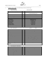
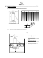
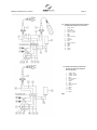
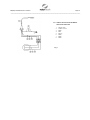
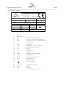
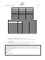
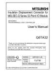
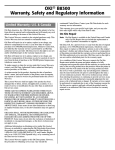
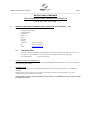
Filterpump User Manual Issue 2 04/05/12 Page 1 _____________________________________________________________________________ ROTORFLUSH FILTERPUMPS USE AND MAINTENANCE INSTRUCTION MANUAL TO BE KEPT BY THE USER 1. MANUFACTURER AND FILTERPUMP IDENTIFICATION DATA (as per EEC98/37 p. 1.7.4a) 1.1. Manufacturer Data Rotorflush Filters Limited Langmoor Manor Charmouth Bridport Dorset DT6 6BU England Telephone: +44 (0) 1297 560229 Fax: +44 (0) 1297 560110 Email: [email protected] 1.2 Filterpump Data Description: Submersible Filterpump Model E8020T, E8015-16T, E8015-16M, 8012-16M, 8012-16T, 401516M, 4015-16T, 4012-16M, 4012-16T 4010-16M, 4010-16T 4008-16M 4008-16T, 4006-16M, Year of manufacture: see plate on Filterpump 2. TECHNICAL ASSISTANCE INFORMATION If a malfunction of the Filterpump is not covered in the TROUBLESHOOTING table (Section 14.1) contact Rotorflush Filters Ltd at the above address. 3. INTRODUCTION This publication contains all necessary information and instructions for the use and maintenance of your Rotorflush Filterpump. Follow the advice given to ensure correct operation and optimum performance of the Filterpump. For any other information, please contact Rotorflush Filters Ltd. THESE INSTRUCTIONS AND ILLUSTRATIONS ARE SUBJECT TO COPYRIGHT AND MUST NOT BE COPIED IN WHOLE OR IN PART Filterpump User Manual Issue 2 04/05/12 Page 2 _____________________________________________________________________________ 4. CONTENTS 1. 2. 3. 4. 5. 6. 7. 8. 9. 10. 11. 12. 13. 14. 15. 16. 17. Manufacturer and Machine Identification Data Information on Technical Assistance Introduction Contents General Safety Warnings 5.1. Preventive measures to be taken by the user 5.2. Significant protection and precautions Description 6.1. General description 6.2. Technical and construction features Technical Data Card 7.1. Pump technical data 7.2. Motor technical data 7.3. Filter technical data Contemplated and Non-contemplated Use 8.1. Contemplated conditions of use 8.2. Non-contemplated conditions of use Handling and Transport 9.1. Unpacking 9.2. Handling and De-installing 9.3. Transport Installation 10.1. Fixed installation 10.2. Temporary installation Assembly and Disassembly Preparation for Use 12.1. Connection to electricity supply 12.2. Adjusting and registering Use and Start-up 13.1. Starting 13.2. Version with float switch 13.3. Version without float switch Maintenance and Repairs 14.1. Troubleshooting Technical Information 15.1. Diagram of Filterpump Dimensions, packing and weights (fig. 1) 15.2. Diagram for installing with minimum functional spaces (fig. 2) 15.3. Diagram for single phase Filterpump with automatic float switch (fig. 3) 15.4. Wiring diagram for single-phase Filterpump without automatic float switch (fig. 4) 15.5. Wiring diagram for three-phase Filterpump (fig. 5) 15.6. Plate example Information on Air-borne Noise Waste disposal Filterpump User Manual Issue 2 04/05/12 Page 3 _____________________________________________________________________________ 5. GENERAL SAFETY WARNINGS FAILURE TO OBSERVE THESE WARNINGS AND/OR ANY TAMPERING WITH THE FILTERPUMP EXEMPTS ROTORFLUSH FILTERS LTD FROM ALL RESPONSIBILITY IN THE EVENT OF PERSONAL INJURY OR DAMAGE TO EQUIPMENT OR PROPERTY AND/OR TO THE FILTERPUMP Read this manual carefully and check to ensure that the Filterpump has been properly installed and connected in accordance with relevant safety standards before starting the Filterpump. There are no RESIDUAL RISKS with Rotorflush Filterpumps. No particular technical skills are required to use Rotorflush Filterpumps. No personal safety devices (precaution devices) are required to use Rotorflush Filterpumps. 5.1. Preventive Measures to be Taken by the User d) e) f) g) h) 5.2. a) The user must specifically comply with all the accident prevention regulations in force in the respective countries in which the Filterpump is being used; the indications given in Section 7.1 must be scrupulously followed. b) c) During operation make sure that nobody is in the water Before undertaking any repairs or maintenance to the Filterpump, isolate the electricity supply by removing the plug from the socket and/or turning off the switch (if provided). This will prevent accidental starting which could cause personal injury or damage to equipment or property. Any maintenance operation, installation or moving the Filterpump with the electrical system live may cause serious injury and could prove fatal. During operation, avoid moving the Filterpump. Before using the Filterpump, always check that the cable and all electrical devices are in perfect working order. When starting up the Filterpump (by turning on the switch, if provided, or by inserting the plug in the socket) ensure (i) you do not have wet hands (ii) you are not standing in water and (iii) you are not barefoot. The user must not carry out under his/her own initiative any operations or tasks not contemplated in this manual. Significant Protection and Precautions (as per EEC 98/37 p. 1.1.2 and 1.7.2; EN 292-2 p.5). Rotorflush Filterpumps are designed so that all moving parts are shrouded by protective casings. Rotorflush Filter Ltd declines all responsibility in the event of injury or damage caused as a result of tampering with these devices. Each lead or live part is electrically insulated to earth; there is also a further safety device in that the accessible conductive parts are connected to an earth lead so that the parts within reach cannot become dangerous in the event of failure of the principal insulation. Filterpump User Manual Issue 2 04/05/12 Page 4 _____________________________________________________________________________ 6. DESCRIPTION 6.1. General Description Rotorflush EB Series Filterpumps are all similar from the functional and constructive point of view; the only differences are the following: power flow rate head electric power supply (single phase or three phase) weight dimensions Rotorflush Filterpumps are used for handling water containing total suspended solids not greater than 2,000 mg/litre dry weight at temperatures up to 35°C (Section 7.1). Unwanted solids are separated by a self-cleaning filter which is continuously backwashed with filtered water pumped though a dual-headed rotor by a secondary impeller mounted on an extended impeller shaft attached to the pump. Thanks to their small bulk and ease of transport, they may be used for fixed or temporary installations, with or without automatic start. Rotorflush Filterpumps are designed for long life and constant performance if used according to the instructions given in Sections 8 and 14. 6.2. Technical and Construction Characteristics Rotorflush Filterpumps are designed and built to the following design and construction standards: RISKS OF A MECHANICAL NATURE (Annex 1, Machines Directive): - EN 292-1 and EN 292-2 RISKS OF AN ELECTRICAL NATURE (Annex 1, Machines Directive): - EN 292-1 and EN 292-2 - CEI EN 60 335-2-41 RISKS OF VARIOUS NATURE (Annex 1, Machines Directive): EEC 98/37 - Annex 1 Electrical components and their circuits installed in Rotorflush Filterpumps comply with standards CEI EN 60204-1. Filterpump User Manual Issue 2 04/05/12 Page 5 _____________________________________________________________________________ 7. TECHNICAL DATA CARD (as per EEC 98/37 p.1.1.2 and 1.7.2; EN 292-2 p.5) 7.1. Pump Technical Data 8015M and 8020T Maximum temperature of pumped fluid °C 35 (as per EN 60335-2-41 for household use Maximum immersion depth……. m = (length of electric cable-2) to a maximum of 20m. for model with floating switch. Maximum total head m See plate on Filterpump Length and type of power cable m 10 (20) H07 RN-F Maximum working pressure kPa (bar) 1000 (10) Type of impeller Closed Type of seal on shaft Duplex seal with oil-lubricated intermediate chamber Type of bearing Shielded ball bearing Delivery diameter Threaded Rp 1 1/4 Impeller material Technopolymer Stage material Technopolymer Diffusers material Technopolymer Seal holder material Stainless steel Maximum number of hourly revolutions 7.2. 25 Motor Technical Data Power 8015M kW 8020T 1.2 Type 1.6 Dry submerged Polarity No. 2 Insulation class F Degree of protection IP68 Type of duty Continuous Phase - frequency - voltage See plate on Filterpump See fig. 8 for voltages and equivalent tolerances Overpower protection Thermal-magnetic tripswitch (single phase only) Condenser Included (single phase only) Motor structure material Stainless steel Shaft material Stainless steel Cable protective covering Neoprene Maximum number of equally distributed hourly revolutions 7.3. 10m 25 Self-cleaning Filter Technical Data Filter Area 273 cm2 Filter Mesh Monofilament nylon 250 micron apertures Materials: Filter cage and rotor 316 stainless steel Rotor thrust bearing Silicon Carbide Rotor bearing housings Acetal copolymer Rotor impeller Glass filled Nylon Rotor impeller bush Brass Rotor impeller extension shaft 316 stainless steel Filterpump User Manual Issue 2 04/05/12 Page 6 _____________________________________________________________________________ 8. 9. CONTEMPLATED AND NON-CONTEMPLATED USE WARNING Failure to respect the prescribed limits constitutes a situation of use that is technically improper and may endanger the safety of persons and thus EXEMPTS ROTORFLUSH FILTERS LTD FROM ANY RESPONSIBILITY IN THE EVENT OF ACCIDENTS TO PERSONS OR DAMAGE TO EQUIPMENT OR PROPERTY AND/OR TO THE FILTERPUMP, THEREBY RENDERING THE GUARANTEE INVALID. 8.4 Contemplated Conditions of Use Rotorflush Filterpumps are suitable for pumping water with a total suspended solids loading not exceeding 2000mg/litre dry weight. Oily/fatty/sticky solids will reduce filter performance. They can be used with pressurisation units. Use the Filterpump in keeping with its technical characteristics (Section 7). 8.5 Non-Contemplated Conditions of Use Rotorflush Filterpumps must not be installed in swimming pools and similar environments, for pumping fluids having a total suspended solids loading of not more than 1000 mg/litre dry weight, water containing acids and corrosive liquids in general, water with temperatures over 35°C (as per EN 60335 - 2 -41), sea water, inflammable and dangerous liquids in general. Rotorflush Filterpumps must never be run without water. HANDLING AND TRANSPORT (as per EEC 98/37 p. 1.7.4.a; EN 292-2 p.5 1.1.a) 9.1 Unpacking Check that there are no breakages or severe dents in the packing; if there are, point this out immediately to the person who delivers the material. After removing the Filterpump from the package, check that it has not suffered any damage during transit; if damage is found, inform the dealer within 8 days of delivery. Check that the specifications stated on the plate of the Filterpump are the same as you requested in your order. 9.2 Handling and De-installing WARNING FAILURE TO FOLLOW THESE INSTRUCTIONS MAY CAUSE THE FILTERPUMP TO FALL AND SUFFER SEVERE DAMAGE. NEVER UNDER ANY CIRCUMSTANCES USE THE POWER CABLE TO LIFT OR DRAG THE FILTERPUMP. To handle or de-install the Filterpump you must: remove the plug from the power socket and/or switch off the switch, if provided; roll up and hold the electric power cable in your hand; lift the Filterpump and the delivery pipe with the handle provided. If the Filterpump is set up for fixed applications, perform the following operations before handling it: 9.3 - remove the plug from the power socket and/or switch off the switch , if provided; - unscrew any clamps and remove the delivery pipe; roll up and hold the electric power cable in your hand; lift the Filterpump and the delivery pipe with the handle provided. Transport The Filterpump is packed in a cardboard box for transport; as its total weight and bulk are not excessive (fig 1), transport presents no difficulties. However, check the gross weight marked on the box. Filterpump User Manual Issue 2 04/05/12 Page 7 _____________________________________________________________________________ 10. INSTALLATION (as per EEC 98/37 p. 1.7.4.a; EN 292-2 p.5.1.1b) WARNING TO LIFT OR LOWER THE FILTERPUMP, USE A ROPE FIXED TO THE HANDLE; NEVER USE THE ELECTRIC POWER CABLE. The Filterpump must be protected by the installation of dry run protection. If the filter blocks because of high levels of solids in the water or for some other reason the pump will run without water. This will cause damage to the pump and will invalidate any guarantee. Dry run protection can be by monitoring the power factor of the motor or by monitoring the flow/pressure from the delivery pipe. Rotorflush can provide dry run protection for its pumps and it is strongly advised that the correct protection is purchased from Rotorflush Filters 10.1 Fixed Installation The Filterpump may be installed upright or horizontally although the self-cleaning filter will work better in the upright position 10.1.1 The Filterpump should be fully submerged if possible although this is not necessary except for frost protection. The Filterpump will operate continuously if at least 350mm of the filter unit and suction end of the pump are submerged in water at a temperature of less than 35°C. 10.1.2 There must be a gap of at least 100mm around and underneath the filter unit, although there is no need for a gap under the Filterpump when operated in the upright position if there is a flow of fluid past the filter pump to take detritus away from the screen (e.g. when installing in a flowing river or flume the filter unit at the suction end of the Filterpump) at all times to allow solid particles to fall or be washed clear of the filter screen. Due allowance must the made to allow for any build-up of solids underneath the filter and any detritus, sludge etc must be removed from time to time to ensure this does not come within 100mm of the filter. 10.1.3 When lowering the Filterpump into a well or tank, ensure that it is at least 100mm above the bottom. 10.1.4 Be careful with the power cable when lowering the Filterpump into a borehole. It is advisable to tie the power cable to the delivery pipe every two or three metres. 10.1.5 When positioning the Filterpump, observe the minimum required distances (fig. 2) from walls, from the sides of the drain, tank or other location, so as to allow functioning, use and maintenance operations in safe conditions (as per EN 292-2 p.5.5.1.b). 10.1.6 It is recommended that G 1¼" rigid pipes (metal or plastic) be attached to the Filterpump with clamps of a suitable size. 10.1.7 Anchor the pipes to the edge of the basin or tank with a pipe clamping bracket. 10.1.8 If there is the need to install a non-return valve onto the delivery pipes, make sure it is placed away from the Filterpump filter screen to avoid priming problems when first starting or after empting. Temporary Installation (for Temporary Use) 10.1.9 The Filterpump may be installed upright or horizontally. (As above) 10.1.10 The Filterpump should be fully submerged if possible (as above) but it will operate continuously if at least 350mm of the filter unit and suction end of the pump are submerged in water at a temperature of less than 25°C. 10.1.11 There must be a gap of at least 100mm around and underneath the filter unit, although there is no need for a gap under the Filterpump when operated in the upright position if there is a flow of fluid past the filter pump to take detritus away from the screen( e.g. when installing in a flowing river or flume at the suction end of the Filterpump) at all times to allow solid particles to fall or be washed clear of the filter screen. Due allowance must the made to allow for any build-up of solids underneath the filter and any detritus, sludge etc must be removed from time to time to ensure this does not come within 100mm of the filter. 10.1.12 When lowering the Filterpump into a well or tank, ensure that it is at least 100mm above the bottom. 10.1.13 Be careful with the power cable when lowering the Filterpump into a borehole. It is advisable to tie the power cable to the delivery pipe every two or three metres. 10.1.14 When positioning the Filterpump, observe the minimum required distances (fig. 2) from walls, from the sides of the drain, tank or other location, so as to allow functioning, use and maintenance operations in safe conditions (as per EN 292-2 p.5.5.1.b). Filterpump User Manual Issue 2 04/05/12 Page 8 _____________________________________________________________________________ 10.1.15 10.1.16 It is recommended that G 1¼" rigid pipes (metal or plastic) be attached to the Filterpump with clamps of a suitable size. If there is the need to install a non-return valve onto the delivery pipes, make sure it is placed away from the Filterpump to avoid priming problems when first starting or after empting. Filterpump User Manual Issue 2 04/05/12 Page 9 _____________________________________________________________________________ 11. ASSEMBLY AND DISASSEMBLY (as per EEC 98/37 p.1.7.4.a). The Filterpump has no separate parts or accessories, so no assembly is required for installation The user must not attempt to disassemble the Filterpump and should contact Rotorflush Filters for advice if any further disassembly is required. FAILURE TO COMPLY WITH THIS RULE RENDERS THE GUARANTEE INVALID. Filterpump User Manual Issue 2 04/05/12 Page 10 _____________________________________________________________________________ 12. PREPARATION FOR USE (as per EEC 98/37 p.1.7.4.a, EN 292-2 p.5.1.3). On three phase Filterpumps, check the direction of rotation of the motor. The impeller must turn in a clockwise direction when viewing the Filterpump from above (see arrow on pump). As it is not possible to check the direction of rotation of the impeller visually, you should proceed as follows: before anchoring the Filterpump to the system, connect the power cables to the electric panel and turn on the mains switch for a moment; the Filterpump will start up with a kick back.. To be sure that the impeller turns in the right direction, the kick-back must be in an anti -clockwise direction (when viewing the Filterpump from above). Keep in mind that the Filterpump achieves its maximum flow rate only when the connection of the phases is appropriate; a wrong connection resulting in the rotation being in the opposite direction will greatly reduce its performance. If the pump is run in the wrong direction for more than a few seconds it will be damaged severely and will invalidate any guarantee. 12.1 Connection to Electrical Supply 12.1.1 For connection to the mains, use the power cable complying with IEC standards supplied with the Filterpump; connect by means of a bi-polarity disconnecting switch (with min. 3mm contact opening), or another similar device. Remember to take into account the power installed (0.9 - 1.8 KW), the mains voltage and the number of phases (section 7.2). 12.1.2 The mains must have an effective earthing system in accordance with the electrical standards existing in the user's country: this is the installer's responsibility. 12.1.3 In the single phase version it is necessary to use a plug with a double earthing contact complying with CEE Pub.7 norms (fig 3); earthing contact takes place when the plug is connected to the socket. The connection of the plug to the mains must be done indoors, away from any sprays and jets of water or rain. Make sure you have easy access to the plug. An automatic reset thermal protective device protects the motor against overloads. A surge protection device must be installed on the input side of the mains supply to protect the electrical equipment supply conductors. 12.1.4 A power cable with a yellow and green wire for earthing (figure 5) is supplied with the three phase version; this must be connected to an efficient earthing system in accordance with the electrical standards applicable to the user's country. The three phase version does not have an internal motor-protector, so an appropriate overload protection device must be provided and installed by a qualified electrician. The power supply for the Filterpump must arrive by means of the following: 12.1.4.1 A bi-polarity disconnecting switch (with min. 3mm contact opening) 12.1.4.2 A motor protection thermal-magnetic tripswitch calibrated to the nominal current indicated on the identification plate. 12.1.4.3 A surge protection device, to protect the electrical equipment supply conductors. The sectioning device must be interblocking or positioned in a place which is easily visible from the site of the Filterpump. 12.1.4.4 Whenever the Filterpump is either in a fixed installation and/or placed outside, it is necessary for both the single phase and the three phase version to install a high sensitivity differential switch in the installation (0.03A). All electrical connections must be carried out by a qualified electrician. 12.2 Adjusting and Registering (as per EEC 98/37 p.1.7.4.a; EN 292-2 p.5.5.1.d) The only thing that needs checking once installation is complete is the length of the cable with float (in versions that have one) with respect to the minimum and maximum water level (fig. 2). Filterpump User Manual Issue 2 04/05/12 Page 11 _____________________________________________________________________________ 13. USE AND START-UP (as per EEC 98/37 p.1.7.4.a; EN 292-2 p. 5.5.1.d) If the system is supplied with a delivery gate valve, the water level must never be lower than the filter screen, even when the pump is not being used. If you fail to observe this, the Filterpump will run out of water and you will have great difficulty starting the Filterpump again. 13.1 Starting Never switch on the Filterpump until it is placed and installed in its final operational position. It is possible to have leakage of the Filterpump oil into the pumped liquid; however, this is not harmful to health. 13.2 Version With Floating Switch To start up the Filterpump, connect the plug and/or turn on the switch. The Filterpump will start automatically as soon as the water level, regulated by the floating switch, reaches the minimum level (fig.2). The performance of the floating switch has been designed by the manufacturer to assure a minimum immersion level in the OFF position. 9.1 Version Without Floating Switch To start up the Filterpump, connect the plug and/or turn on the switch. When the water level reaches the minimum level (fig. 2), disconnect the plug and/or turn off the switch. Filterpump User Manual Issue 2 04/05/12 Page 12 _____________________________________________________________________________ 14. MAINTENANCE AND REPAIRS (as per EEC 98/37 p.1.6; EN 292-2 p.5.5.1.e) BEFORE CARRYING OUT ANY MAINTENANCE OPERATIONS, DISCONNECT THE PLUG AND/OR SWITCH OFF. FOR ANY REPAIR JOBS DURING THE GUARANTEE PERIOD, THE USER MUST CONTACT ROTORFLUSH FILTERS LTD. FAILURE TO OBSERVE THIS RULE RENDERS THE GUARANTEE INVALID. AFTER THE GUARANTEE PERIOD, ALL MAINTENANCE OPERATIONS, REPAIR JOBS AND/OR REPLACEMENTS, MUST BE CARRIED OUT BY SKILLED TECHNICIANS ONLY. To ensure correct functioning and long life of the Filterpump, the Rotorflush filter unit should be inspected and cleaned every two months. The amount of cleaning required will depend on the liquid being pumped in some instances more frequent manual cleaning of the filter screen may be required, for example where biological growth occurs on the filter screen or oily/fatty deposits are found to build up on the filter screen). Stainless steel screens should be thoroughly cleaned with a pressure washer. Nylon screens should be cleaned with gentle running water or replaced. It is recommended that nylon screens are replaced every 2000 hours of use or every 6 months whichever time occurs first.This is the only maintenance required by the Filterpump. Check the condition of the electric power cable; if it is damaged, contact the dealer or Rotorflush Filters Ltd to have it replaced. 14.1 Troubleshooting TYPE OF FAULT: The pump does not work (the motor does not turn over) CAUSE REMEDY No electric power Check the contactor on the electric line Plug not inserted Check power connection to the line Automatic switch has tripped Reset the switch and check the cause Float blocked Check that the float reached ON level Thermal protection has tripped (single phase) This resets automatically Protection fuses are burnt out (three-phase) Replace the fuses with same type Faulty motor or capacitor Contact Rotorflush Filters Ltd TYPE OF FAULT: The pump does not work (the motor turns over) CAUSE REMEDY Intake filter blocked Cleans the filter (chapter 14) Non-return valve blocked Clean the valve and check its operation The pump does not start up Check minimum water level Check function of delivery gate valve Hole in filter screen causing pump to block with detritus Return to Rotorflush for repairs TYPE OF FAULT: The pump works at a low flow rate CAUSE REMEDY Dirty deliver pipe Clean pipe Clogged filter screen Clean, if continues to be a problem, contact Rotorflush for advice Dirty Impellers Check filter screen for damage. If damaged contact Rotorflush Filters for replacement screen) Non-return valve blocked Clean the valve and check its operation Water level too low Switch off the pump Wrong direction of rotation Check the direction of rotation (three-phase only, section 12) Wrong supply voltage Feed the pump with the voltage indicated on the rating plate TYPE OF FAULT: The pump stops after brief periods of operation (tripping the thermal protection) CAUSE REMEDY Liquid temperature too high The temperature exceeds the technical limits of the pump Internal defect Contact Rotorflush Filters Ltd Filterpump User Manual Issue 2 04/05/12 Page 13 _____________________________________________________________________________ 15. TECHNICAL INFORMATION 15.1 Diagram of Filterpump Dimensions, Packing and Weights Fig 1 MODEL DIMENSIONS (mm) H W X PACKING (mm) Y 8020-16 730 210 8015-16 634 8012-16 4015-16 WEIGHT (Kg) Z 290 240 780 20 210 290 240 780 19 610 210 290 240 780 18 686 210 290 240 780 20 4012-16 660 210 290 240 780 19 4010-16 609 210 290 240 780 18 4008-16 583 210 290 240 780 17 4006-16 583 210 290 240 78- 15 X Z Y 15.2 Diagram for Installation with Minimum Functional Distances Fig 2 A 100mm min gap to side of tank B 100mm min gap to top of sediment or detritus at bottom of tank C With automatic float switch: 350mm minimum immersion from bottom of filter. Without automatic float switch: 130mm minimum immersion from bottom of filter. D D C A B If used with automatic float switch allow 600mm min gap to side of tank Filterpump User Manual Issue 2 04/05/12 Page 14 _____________________________________________________________________________ 15.3 WIRING DIAGRAM FOR SINGLE-PHASE FILTERPUMP WITH FLOAT SWITCH 1. 2. 3. 4. 5. 6. 7. 8. 9. 10. 11. 12. 13. 14. 15. 16. Supply cable Float cable Yellow / Green Yellow / Green Blue Blue Black or Brown Brown Capacitor Start Motor protector Black White Run Green White 15.4 WIRING DIAGRAM FOR SINGLEPHASE FILTERPUMP WITHOUT FLOAT SWITCH 1. 2. 3. 4. 5. 6. 7. 8. 9. 10. 11. 12. 13. 14. Fig 4 Supply cable Yellow / Green Yellow / Green Blue Black or Brown Capacitor Motor Start Motor protector Black White Run Green White Filterpump User Manual Issue 2 04/05/12 Page 15 _____________________________________________________________________________ 15.5 WIRING DIAGRAM FOR THREEPHASE FILTERPUMP 1. 2. 3. 4. 5. 6. 7. 8. Fig 5 Supply cable Yellow / Green Black Blue Brown Black Black Black Filterpump User Manual Issue 2 04/05/12 Page 16 _____________________________________________________________________________ 15.6 Rating Plate Example ROTORFLUSH FILTERS LTD Langmoor Manor Charmouth DT6 6BU UK +44 (0)1297 560229 TYPE MADE IN UK 03 (1) Q (3) l/min. V~ (2) H (4) (6) P2 (8) kW HP P1 (12) kW Phase ΜF (15) Vc Ins.C. F (19) S1 (9) Hz (10) (13) Min (14) (16) Weight (20) Kg IP (17) P/N (21) Hmax (5) m Hmin (7) m A (11) __ (18) m (1) Model (2) Serial Number (3) "Q" Min and max capacity of duty point (4) "H" Total head in relation to min and max capacity (5) "Hmax" Max total head (usually corresponds to the shut-off (6) "V~" Nominal voltage (7) "Hmin" Min total head (8) "P2" Nominal power of the motor (shaft power) (9) "HP" Nominal horse power of the motor (10) "Hz" Frequency (11) "A" Nominal current (12) "P1" Input power (13) "Phase" Type of motor (single or three phase) (14) "min-1" Revolution speed (15) "F" Capacitor data (single phase only) (16) "Vc" Capacitor voltage (17) "IP" Protection classification (18) " " Max operational depth (19) "Ins. C. F S1" Insulation class and duty type (20) "Weight" Weight (21) "P/N" Part number m 03 Year of manufacture (eg 03 = 2003) Filterpump User Manual Issue 2 04/05/12 Page 17 _____________________________________________________________________________ SINGLE PHASE Voltage indicated on the label 110 [V] Tolerance Operating Range +/- 6% 103 - 107 [V] 115 [V] +/- 6% 108 - 122 [V] 220 [V] +/- 6% 207 - 233 [V] 230 [V] +/- 10% 207 - 253 [V] 240 [V] +/- 6% 226 - 255 [V] 208 - 230 [V] +/- 6% 196 - 244 [V] 220 - 240 [V] +/- 6% 207 - 255 [V] 230 - 240 [V] - 10% + 6% 207 - 255 [V] Other [V] +/- 5% - THREE PHASE Voltage indicated on the label Tolerance Operating Range Delta Connection "" Star Connection "Y" 220 / 380 Y [V] +/- 6% 207 -233 357 - 403 Y [V] 240 / 415 Y [V] +/- 6% 226 - 253 390 - 440 Y [V] 230 / 400 Y [V] +/- 10% 207 - 253 360 - 440 Y [V] 220 - 240 / 380 - 415 Y [V] +/- 5% 207 - 253 360 - 440 Y [V] 230 - 240 / 400 - 415 Y [V] - 10% + 6% 207 - 253 360 - 440 Y [V] 230 [V] +/- 10% 207 - 253 Not available 400 [V] +/- 10% Not available 360 - 440 Y [V] 208 - 230 [V] +/- 5% 198 - 242 Not available 460 [V] +/- 10% Not available 414 - 506 Y [V] Other [V] +/- 5% - - Fig. 8 16. INFORMATION ON AIR-BORNE NOISE (as per EEC 89/392 p. 1.7.4.f) The weighted sound pressure level A produced by the Filterpump does not exceed the value of 70 dB(A). 17. WASTE DISPOSAL Before scrapping the Filterpump, make sure the lubricating oil is separated from the other components. Do not dump lubricating oil in the environment. It must be disposed of properly. DECLARATION OF CONFORMITY We, ROTORFLUSH FILTERS LIMITED, declare under our own responsibility that our products Filterpump E8015 and E8020 conform to the Machinery Directive 89/392/CEE as modified by Directives 91/368/CEE, 93/44/CEE. 93/68/CEE, to the Low Tension Directive 73/23/CEE, as modified by Directive 93/68/CEE and to the Electromagnetic Compatibility Directive 89/336/CEE as modified by Directive 93/68/CEE. J Hosford Proprietor Rotorflush Filters USE AND MAINTENANCE INSTRUCTION MANUAL for ROTORFLUSH FILTERPUMPS Models E4004 –E8020 For three phase pumps it is imperative that electrical connections are made so that the impellers rotate in the correct direction. If the pumps are run in the wrong direction for more than a few seconds serious damage may result which will invalidate the guarantee. Read page 9 paragraph 12 before installation for the method of checking correct direction of rotation. Although the filters are self cleaning there may over time be a build up of detritus in the pores of the mesh which the self cleaning mechanism can not remove. For stainless steel filter mesh use a pressure washer to very thoroughly clean the outside of the mesh. For nylon screens either clean low pressure water or replacement inserts are available from Rotorflush Filters If the pump is run with the filter screen clogged it may cause the pump to overheat and seriously damage the motor invalidating the guarantee. In most conditions the filter should be cleaned every 2 months in some situations it may require more frequent cleaning, particularly with 50 and 100 micron screens, see paragraph 14