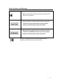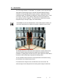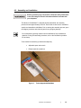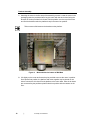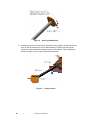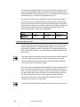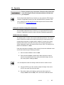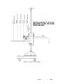
1
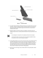
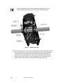
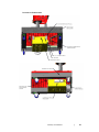
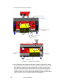
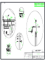
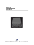
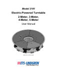
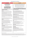
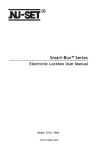
Model 2175 MiniMast™
User Manual
ETS-Lindgren L.P. reserves the right to make changes to any products herein to improve
functioning or design. Although the information in this document has been carefully reviewed and
is believed to be reliable, ETS-Lindgren does not assume any liability arising out of the
application or use of any product or circuit described herein; nor does it convey any license under
its patent rights nor the rights of others. All trademarks are the property of their respective
owners.
© Copyright 2005–2008 by ETS-Lindgren L.P. All Rights Reserved. No part of this
document may be copied by any means without written permission from ETS-Lindgren
L.P.
Trademarks used in this document: The ETS-Lindgren logo and MiniMast are trademarks of
ETS-Lindgren L.P.
Revision Record | Model 2175 MiniMast, MANUAL | Part #399770, Rev. C
Revision
ii
Description
Date
A
Initial Release
April, 2005
B
Updates
November, 2005
C
Design updates; rebrand
September, 2008
|
Table of Contents
Notes, Cautions, and Warnings ......................................................................... v 1.0 Introduction ................................................................................................... 7 Standard Configuration ............................................................................................................. 8 Optional Items ........................................................................................................................... 9 ETS-Lindgren Product Information Bulletin .............................................................................. 9 2.0 Maintenance ................................................................................................ 11 Maintenance Recommendations ............................................................................................ 11 Routine Check .................................................................................................................. 11 Six-Month Check .............................................................................................................. 12 Replacement and Optional Parts ............................................................................................ 12 Service Procedures ................................................................................................................. 12 3.0 Specifications.............................................................................................. 13 Electrical Specifications .......................................................................................................... 13 Physical Specifications............................................................................................................ 13 4.0 Assembly and Installation .......................................................................... 15 Product Assembly ................................................................................................................... 16 Electrical Installation ............................................................................................................... 23 Connecting the Controller ....................................................................................................... 24 Carrier Safety Brake................................................................................................................ 25 5.0 Operation ..................................................................................................... 27 Editing the Controller Configuration Parameters .................................................................... 27 MiniMast Encoder Calibration ................................................................................................. 27 Antenna Mounting Instructions ............................................................................................... 28 Pre-Operational Checks .......................................................................................................... 30 Start-Up and Safe Shutdown .................................................................................................. 30 Infrared (IR) Controller ............................................................................................................ 30 Appendix A: Warranty ...................................................................................... 33 Appendix B: Drawings ...................................................................................... 35 Appendix C: EC Declaration of Conformity .................................................... 37 |
iii
This page intentionally left blank.
iv
|
Notes, Cautions, and Warnings
Note: Denotes helpful information intended to provide tips for
better use of the product.
Caution: Denotes a hazard. Failure to follow instructions
could result in minor personal injury and/or property
damage. Included text gives proper procedures.
Warning: Denotes a hazard. Failure to follow instructions
could result in SEVERE personal injury and/or property
damage. Included text gives proper procedures.
See the ETS-Lindgren Product Information Bulletin for safety,
regulatory, and other product marking information.
|
v
This page intentionally left blank.
vi
|
1.0 Introduction
The ETS-Lindgren Model 2175 MiniMast™ is a portable, electric-powered mast
and platform system designed to be used with the Model 2090 Multi-Device
Controller (or next generation ETS-Lindgren controller, if applicable) for EMI
compliance testing. The MiniMast is designed for antenna scanning from 1 meter
to 4 meters. The mast, carrier, platform, lifting rope, and guying system are
non-conductive and non-magnetic. The mast section is constructed of square
fiberglass tubing for strength, rigidity, and “weatherability”.
The MiniMast may also be manufactured in custom mast heights. Contact your
local sales representative for additional information regarding custom height.
The MiniMast features an offset boom that maintains a constant rotational axis
along the centerline when the antenna is rotated from horizontal to vertical
polarization. A cable guide at the back end of the boom feeds the coaxial cable to
the antenna while maintaining the appropriate bending radius.
The air polarization feature allows for remote polarization of the antenna using
the controller or the infrared remote control.
For antennas with a stinger mount, the offset boom can be removed. The
antenna stinger is then clamped into the mounting block using the hand knob.
Introduction
|
7
The antenna carrier is raised and lowered by a fractional horsepower, electric,
variable speed motor. A worm-type gearbox driven by the motor provides the
adequate torque needed to raise and lower the carrier and prevents the carrier
from back-driving the motor. The motor and associated electronics are contained
in a shielded enclosure mounted beneath the platform of the unit. Under
command of the controller, the motor typically positions the carrier within
one centimeter of the desired location. To prevent over travel of the carrier in
either direction of movement, the mast system has integral fiber optic limits. Soft
limits may be set within the travel range provided by the mechanical limits using
the controller.
The motor base is connected to the controller through a twin fiber optic cable
assembly. This fiber optic cable transmits both directional control and position
information. Power to the motor base is provided locally to the motor through a
detachable, grounded power cable.
A carrier brake is mounted on the carrier assembly. In the event that the carrier is
released from the rope suspension, a spring-loaded cam locks the brake into
position against the mast and locks the carrier so that further vertical movement
is restricted.
The carrier brake is intended to provide some protection to the
carrier and the antenna; it is not a fail-safe brake for protection
to personnel. Personnel operating this equipment should be
instructed to stay clear of the carrier and boom at all times
whether or not the carrier is moving.
Polypropylene braided rope guy lines are provided for installations requiring the
mast to be guyed and must be firmly anchored for vertical stability. Use of the
guy lines is recommended in all applications to provide maximum stability.
Standard Configuration
8
•
Motor, 220 VAC, nominal
•
Input frequency 50 or 60 Hz
•
Tower platform casters for movement of the unit
•
Offset antenna mount
•
Stinger antenna mount
•
10-meter fiber optic control cable for inside chamber
|
Introduction
•
3-meter fiber optic control cable for connection to Model 2090 controller (or
next generation ETS-Lindgren controller, if applicable) outside chamber
•
Two ST-to-ST bulkhead feedthroughs provide a means to penetrate a shield
wall and maintain the integrity of the shielded enclosure
•
Air polarization (adjustable speed)
•
Infrared (IR) Remote
Optional Items
•
Model 2090 Multi-Device Controller (or next generation ETS-Lindgren
controller, if applicable): This controller provides control for two separate
devices (for example, towers and turntables) in any combination, plus the
control of four auxiliary devices through a fiber optic interface. The unit
includes a GPIB connection and is compatible with most popular EMI
measurement software.
•
Universal Antenna Mount: This option is a versatile and sturdy mount for
most common antennas.
•
Additional Fiber Optic Cable: Various lengths of fiber optic cable are
available by custom order.
ETS-Lindgren Product Information Bulletin
See the ETS-Lindgren Product Information Bulletin included with your shipment
for the following:
•
Warranty information
•
Safety, regulatory, and other product marking information
•
Steps to receive your shipment
•
Steps to return a component for service
•
ETS Lindgren calibration service
•
ETS Lindgren contact information
Introduction
|
9
This page intentionally left blank.
10
|
Introduction
2.0 Maintenance
Before performing any maintenance, follow the safety
information in the ETS-Lindgren Product Information Bulletin
included with your shipment. Warranty may be void if
maintenance is performed incorrectly.
Maintenance of the Model 2175 MiniMast™ is limited to external components
such as cables or connectors. If you have any questions concerning
maintenance, contact ETS-Lindgren Customer Service.
Maintenance Recommendations
Regular maintenance will prolong the service of your mast assembly. If excessive
wear or damage is found during any of the recommended checks, the system
must be taken out of service and repaired before proceeding. Pneumatic tubing
that appears to be brittle and worn from the effects of UV radiation and inclement
weather should be replaced. Lubricant may be purchased from ETS-Lindgren;
contact the Sales Department at +1-512-531-6400 and request item #890437.
Before performing any maintenance, disconnect the unit and
turn off power.
ROUTINE CHECK
•
Prior to beginning normal operation of the mast, check the mast and
lift system for any signs of damage or excessive wear.
•
Checks the lift rope for excessive wear.
•
Check the mast and carrier for any signs of damage or excessive
wear.
•
Check the guy line(s) to ensure safe and secure and check for
excessive wear.
•
Verify the height readout of the controller and the physical position of
the mast are the same.
•
Verify the antenna is secure.
•
Check routing of all cables to make sure they do not interfere with
the operation of the mast.
Maintenance
|
11
SIX-MONTH CHECK
•
Check the lift rope and guy line for signs of wear.
•
Inspect the components and tubing of the pneumatic polarization
mechanism for signs of corrosion, excessive moisture, and wear.
•
Lubricate the air cylinder O-rings to prevent excessive wear.
•
Check all cabling to the motor base for frayed and worn insulation.
Replacement and Optional Parts
See the drawings located in the back pocket of this manual for the part numbers
to order replacement or optional parts for the MiniMast.
Service Procedures
For the steps to return a system or system component to ETS-Lindgren for
service, see the Product Information Bulletin included with your shipment.
12
|
Maintenance
3.0 Specifications
Electrical Specifications
Nominal AC Voltage
220 VAC
Input Frequency
50/60 Hz
Current Rating
10 Amp service
Phase
Single
Physical Specifications
Base Dimensions
0.90 m x 0.90 m
2.95 ft x 2.95 ft
Weight
81.2 kg (179.0 lb)
Overall Height
4.61 m (15.1 ft)
Mast Height
Nominal 4.5 meters
4 meters standard
Scan Range
Custom height may be specified upon
placement of order
Required Air Pressure
60-80 psi (410-550 kPa)
Carrier Load Rating
Not to exceed 18 kg (40 ft lb)
10 kg (22 lb)
Maximum Loading
See Operation on page 27 for additional
information
Specifications
|
13
This page intentionally left blank.
14
|
Specifications
4.0 Assembly and Installation
Before connecting any components, follow the safety information
in the ETS-Lindgren Product Information Bulletin included with
your shipment.
The Model 2175 MiniMast™ is shipped partially assembled; the assembly
process will take approximately one hour. Ensure that a clear area is available to
unpack and assemble the MiniMast. Prior to starting the assembly process, open
the shipping container and check all parts for any shipping damage.
Do not discard any packing material until the MiniMast is fully installed and
operation. During this assembly procedure, refer to the illustrations provided
for each step.
Tools needed for assembly (included with shipment):
•
Adjustable open-end wrench
•
Phillips head #2 screwdriver
Figure 1:
Tools shipped with MiniMast
Assembly and Installation
|
15
Product Assembly
1. Attaching the motor is the first step of the assembly process. Locate the motor in the
packaging under the positioner base. Lay the motor with the winch drum facing the
direction of the slot provided in the base. Roll the platform over the top of the motor
and find the brackets under the platform that pin the motor into position.
Tabs on motor slide between the brackets on the platform.
Figure 2:
Motor attached to bottom of MiniMast
2. Lift slightly on the motor and insert the pins provided to secure the motor in position.
Once pinned into position, the platform and motor together may be placed on one
side to connect the air hoses from the platform to the motor base. After the air hoses
are connected lay the positioner platform back into position with the casters on the
floor.
16
|
Assembly and Installation
3. Continuing with the assembly, insert the mast into the support angles on the platform.
An axle bushing with stud and nuts for securing in place is on the platform. Carefully
remove the fiber optic cable packed into the lower end of the mast and straighten the
leads. Insert the mast between the two angle supports in approximately the correct
position. Insert the mast axle. After the axle is in place, route the fiber optic limit
cables through the fiber optic hole provided in the platform.
Do not damage the fiber optic cable during this step. Make sure it is out of the
way when inserting the mast axle through the mast.
Figure 3:
Fiber Optic Placement
4. Place the carrier and top cap into the position shown on the mast. Verify that the
carrier brake engages the corner of the mast and all components are oriented as
shown in the following picture. The top cap of the mast bolts into place with an axle
nut and a threaded fiberglass stud and nut combination. Securely tighten the nut and
stud to secure the top cap. The stud should be flush with the nut when tightened in
the proper position. Uncoil the guy ropes and let them hang unobstructed.
Assembly and Installation
|
17
Figure 4:
Securing the Mast Cap
5. Unwind the rope from the winch drum and feed it over the pulleys so that the free end
lines up with the clamp on the carrier brake assembly. Feed the rope through the
clamp on the brake assembly and tighten clamp nuts hand tight. Further adjustment
will be necessary once the mast is completely assembled.
Figure 5:
18
|
Pulley Location
Assembly and Installation
Figure 6:
Screw Placement
6. The mast brackets should be installed according to the orientation shown in previous
illustrations. Using the #2 Phillips screwdriver provided, tighten the screws through
the large and small mast brackets through the mast and into the nut plate that is
already fitted with inserts.
7. Engage the brakes on the swivel casters of the platform so that they will not roll.
Carefully raise the mast to a vertical position and insert the lock pin provided to hold it
in place.
Do not attempt the next portion of the assembly with less than two people.
Care should be taken to keep the carrier from contacting the platform during
this procedure so that it cannot damage the platform.
8. Leaving approximately one turn of rope on the winch drum, pull the hoisting rope tight
through the clamp block on the brake. Once the clamp is fully tightened onto the
rope, tie a loose half-knot on the mast side of the clamp to make sure the rope does
not slip back through the clamp. Once this is accomplished, wind the excess rope
around the clamp portion of the brake so that the brake still functions correctly and
the rope does not interfere with the carrier working properly.
9. Attach the free end of the guy lines to anchors located on the ground plane or within
the chamber.
Assembly and Installation
|
19
Outdoor applications require guying to stabilize the mast against wind. For
outdoor applications, engage the lock on the swivel casters at this time.
Figure 7:
Boom Placement
10. Pull the coiled hose out of the carrier and insert the primary boom as pictured into the
carrier. Note the position of the knobs on the boom gear and on the boom bearings.
The gear back-up roller should be directly behind the rack gear and the cylinder
should be in a fully compressed state. Incorrect horizontal and vertical polarization
angles will result if the cylinder is not fully compressed. Once the primary boom is
locked in place, install the offset boom and the coaxial cable strain relief.
20
|
Assembly and Installation
LOCATION OF CONNECTIONS
Assembly and Installation
|
21
LOCATION OF CONNECTIONS, CONTINUED
Figure 8:
Location of Connections
11. Coiled hoses that were located inside the carrier should be connected to the fittings
on the platform for the polarization to become operable. All connections to the motor
base should be completed at this time including fiber optic limits and control lines,
along with compressed air and electrical power. Route all connections through the
connection entry on the platform tube so they will exit through the connection exit.
Install the platform end covers by positioning and applying pressure to secure them in
place. Check to see that the controller reads horizontal polarization.
22
|
Assembly and Installation
12. Slightly engage the air lines onto the fittings and note the position of the boom.
Energize the air line supply to the motor base. If the boom is in horizontal polarization
(holes in the boom are on top), fully engage the hoses onto the fittings provided. If
the boom is in vertical polarization, turn the air off and reverse the air lines and then
fully engage them on the fittings provided in the platform.
Air line pressure should be between 60–80 psi (4.14–5.52 bar). Do not
exceed 80 psi (5.52 bar).
Keep hands away from any portion of the carrier while
performing this task. Failure to do so may result in
personal injury.
Do not perform any service on the carrier with the air lines
energized.
13. When the MiniMast is in the position where testing will occur, lock the brakes
provided on the swivel casters to prevent movement of the platform.
Electrical Installation
The motor base is provided with a three-conductor AC power cord that is
approximately 2.45m (8 ft) long. Power to the motor base is 220 VAC. The
motor base should be wired to a circuit capable of providing 10 amps of service.
The power cord is to be terminated into an outlet near the motor base. The power
cord is suitable for portable or indoor applications without modification. Ideally,
the power cord would exit the motor base and terminate into an outlet with as
short a cord as possible as the start and stop actions of the motor base create a
small amount of RF noise through the power cord.
If this equipment is to be operated outdoors, precautions must be taken to
protect the MiniMast from the weather. In the event that modifications are
required, the installation should be compliant with all local and national
electrical safety codes.
As with all electrical devices, disconnect the power prior to
servicing the equipment.
A fuse is mounted on the side of the motor enclosure. This fuse provides
protection for the motor and the associated electronics. An additional fuse
provides protection for the DC power supply inside the motor base.
Assembly and Installation
|
23
The branch circuit supplying power to the motor base should be protected from
excess current according to local electrical codes. Whenever possible the motor
should be powered from a separate branch circuit of adequate current capacity to
keep voltage drop to a minimum during startup and running.
Check that the conductor size is adequate for the motor load and the distance
from the mains source. Improperly sized conductors will lead to a high voltage
drop in the power conductors and cause reduced starting torque and premature
motor failure. For longer runs, increase the wire size in accordance with the wire
selection guide shown below. When considering what gauge of wire to use,
never use smaller than 14 AWG for any installation.
Length of wire
@220V
Wire gauge
required
0–15.24 m
(0–50 ft)
15.24–30.48 m
(50–100 ft)
30.45–60.96 m
(100–200 ft)
14 AWG
14 AWG
14 AWG
Connecting the Controller
Any combination of devices may be connected to the two device interface ports
located on the rear panel of the Model 2090 Multi-Device Controller (or next
generation ETS-Lindgren controller, if applicable). The default settings are for a
tower connected to the Device 1 interface port and a turntable connected to the
Device 2 port.
Fiber optic cabling for each device should not be allowed to hang unsupported
from the rear panel of the controller. The fibers and connectors are easily
broken if twisted or bent. Keep the fiber optic cables as straight as possible
from the connector to the protective sheath.
Device connection is accomplished with a dual fiber optic cable included with the
device. This cable terminates into two ST connectors that are identical at both
ends. The cable is symmetrical; either end can be connected to the controller. A
fiber optic cable that connects to the IN port of a controller should, at the other
end, be connected to the OUT port of the motor base. A fiber optic cable
connected to the OUT port of the controller should, at the other end, be
connected to the IN port of the motor base.
The fiber optic mechanical limits must be set before the carrier is able to move.
24
|
Assembly and Installation
Carrier Safety Brake
A safety brake is mounted on the carrier assembly. In the event that the carrier is
released from the rope suspension, a spring-loaded cam jams the brake into
position against the mast and slows the vertical movement of the carrier.
The safety brake is not intended to completely restrict
movement of the carrier. Always exercise extreme caution
when the safety brake is engaged.
To release the carrier safety brake, support the carrier and release the brake
roller. Slide the carrier down to the base of the mast. Replace the carrier rope if
necessary. Reset the current position using the controller before resuming use of
the mast.
Assembly and Installation
|
25
This page intentionally left blank.
26
|
Assembly and Installation
5.0 Operation
Before connecting any components, follow the safety information
in the ETS-Lindgren Product Information Bulletin included with
your shipment.
See the Model 2090 Multi-Device Controller (or next generation ETS-Lindgren
controller, if applicable) manual if you are unfamiliar with the operation of the
unit. A manual is included with each controller shipment and is also available
for download from www.ets-lindgren.com.
Editing the Controller Configuration Parameters
See the Model 2090 Multi-Device Controller (or next generation ETS-Lindgren
controller, if applicable) manual for steps to edit the configuration parameters.
MiniMast Encoder Calibration
The display symbol C refers to the encoder calibration parameter. This setting is
used to convert the encoder count values returned from a motor base into the
corresponding centimeter or degree position reading. For towers, the number
represents the number of encoder counts per meter. Using this parameter, a
variety of standard, retrofit, and custom devices can be used. The setting for the
Model 2175 MiniMast™ is 2000.
If the given value does not appear to work correctly, the encoder calibration value
can be determined using the following procedure:
1. Set the encoder calibration value to 1000.
2. Ensure that the MiniMast is positioned to allow at least one meter of
travel in the upward direction at an easily measurable height, then set
the current position reading to 000.0.
You must adjust the lower limit setting to allow at least one meter of travel.
3. Using the STEP keys of the controller, adjust the height of the carrier
until it is one meter above the start point.
4. Record the reading of the display, ignoring the decimal point (for
example, 200.0 would be 2000). This is the encoder calibration value.
Operation
|
27
If the value is below 1000, the resolution of the encoder is low and the
controller will not provide 0.1 cm resolution, even though the display shows
that digit. If the value has gone past 9999, the encoder has too many counts
per meter and the controller cannot correct for it. In this case, contact
ETS-Lindgren for assistance.
5. Enter this value for the encoder calibration value and reset the limits and
position information.
6. Test the MiniMast by moving it to a known distance and comparing the
display to the measured distance traveled. It may be necessary to adjust
the encoder calibration value up or down slightly depending on the result.
Antenna Mounting Instructions
Antennas may be mounted to the assembly using either the 7/8–14 thread which
is common on ETS-Lindgren brand antennas, or the 1/4–20 thread which is
another common size. The antenna should be mounted on the boom as close to
the carrier as possible. Insert the mounting knobs through the holes on the boom
and align the mounting holes on the antenna with the threaded end of the
mounting knobs. Secure the antenna in place by tightening the threaded knobs
into the receptacle mounting holes on the antenna.
Antennas may also be mounted using the stinger mount adapter included with
the assembly.
28
|
Operation
Figure 9:
Boom Load Limitations
Operation
|
29
Pre-Operational Checks
•
Verify that the power lines are connected to the motor base for the MiniMast,
controller, and any other equipment that will be used to test.
•
Verify the fiber optic cables are connected to the motor base.
•
Verify the limit fibers are connected to the motor base.
•
Verify the antenna connected to the boom is securely mounted in place.
•
Connect the feed cable to the antenna.
•
Verify the load of the antenna is within the operating specifications.
Before moving the carrier on the mast up or down using the
controller or the IR remote, make sure no one is standing near
the boom.
Start-Up and Safe Shutdown
After completing the pre-operational checks, the controller may be turned on by
pressing the power button. See the Model 2090 Multi-Device Controller (or next
generation ETS-Lindgren controller, if applicable) manual for operating
instructions.
Prior to shutting the MiniMast down, move the carrier to an accessible height for
the removal of the antenna. Make sure the unit has come to a complete stop.
Press the power button on the controller to turn it off. Finally, remove power from
the MiniMast.
Infrared (IR) Controller
The motor base features an infrared receiver that will respond to a universal
remote control programmed to a specific protocol. Any remote that continuously
transmits and contains the proper TV protocol can be used.
The basic functions supported are as follows:
Button
30
|
Command
Power
Emergency Stop
Channel Up
Up for linear positioner
Channel Down
Down for linear positioner
Operation
Button
Volume Left
Command
Volume Right
Counterclockwise for rotational
positioner
Clockwise for rotational positioner
Mode
Polarization for linear positioner
Operation
|
31
This page intentionally left blank.
32
|
Operation
Appendix A: Warranty
See the Product Information Bulletin included with your shipment for the
complete ETS-Lindgren warranty for your Model 2175 MiniMast™.
DURATION OF WARRANTIES FOR THE MINIMAST
All product warranties, except the warranty of title, and all remedies for warranty
failures are limited to two years.
Product Warranted
Duration of Warranty Period
Model 2175 MiniMast
2 Years
Warranty
|
33
This page intentionally left blank.
34
|
Warranty
Appendix B: Drawings
These drawings are included in the pocket located on the back cover of the
manual:
•
108983, Crossboom
•
109276, 2175 Carrier
•
109356, 2175 Positioner (2 pages)
Drawings
|
35
This page intentionally left blank.
36
|
Drawings
Appendix C: EC Declaration of Conformity
EC Declaration of Conformity
|
37
REF DRAWING
REVISIONS
ECO#
NOTES:
1) CUT ROPE
1 EA. 29.5 FT. BURN ENDS
AND INSTALL ON WINCH
DRUM. TAPE TO HOLD IN
PLACE FOR SHIPPING.
2) CUT ROPE 3 EA.
18 FEET. BURN ENDS AND
INSTALL IN HOLES PROVIDED
IN MAST CAP FOR GUYING.
REV
5120
B
DESCRIPTION
CHANGED ROPE
DATE
APPROVED
09/14/06
SRK
6
2X APPLY TAPE TO FULL
WIDTH OF BASE AND THEN
APPLY 1" LENGHTS EQUALLY
SPACED, 6" ON CENTER TO
CLOSURE.
17
34.25
34.50
C
D
4
4486.28
176.63
7
A
18
B
6
8
ATTACH TWIN HOSE
TO FITTINGS ON AIR
CYLINDER.
17
UNLESS OTHERWISE SPECIFIED:
DIMENSIONS ARE IN INCHES
TOLERANCES ARE:
DECIMALS
ANGLES
X.XX ± .015
X.XXX ± .005
± .5
CHECKED
NONE
DATE
SRK
12/12/04
RG
2/4/05
MATERIAL
FINISH
TAPE,RECLOSABLE,250 STEMS/IN, I IN. WIDTH
8
40
910899
NUT,5/8-11,FG,BROWN
1
39
910686
SCREW,10-32 X 1/2,PHIL,FLAT,SS
4
38
910455
WASHER,1/4,FLAT,SS
5
37
910451
BOLT,1/4-20 X 1-3/4,HEX,SS
5
36
910357
SCREW,10-32 X 3/4,PHIL,BIND,SS
6
35
910331
SCREW,10-32 X 1/2,PHIL,BIND,SS
9
34
910269
NUT,8-32,HEX,SS
2
33
905194
COUPLING,BULKHEAD,1/8 NPT
2
32
890983
SLEEVING,SLIT-CONVOLUTED,PE,1/4" ID(NOT SHOWN)
23
31
890971
PIN,3/16 X 1" QUICK RELEASE
3
30
890951
PIN,1/2 X 5 GRIP LENGTH,SST
1
29
890950
FITTING,TUBE,1/8 NPT TO .17 ID,RT ANGLE
2
28
890947
HOSE,TWIN,1/8 ID X 1/4 OD,COILED,20 FT
1
27
890946
BUSHING,3/8 ID X 5/8 OD X 3/8,GRAPHITE
2
26
890797
BUMPER,.75 OD,.5 HT,#8 SCREW
2
25
890465
BARB HOSE 11924-1 CLIPPARD
4
24
890464
NUT TUBE 5000-2 CLIPPARD
4
23
860314
ROPE,3/16,2300 LBS
83.5
21
860140
TUBE,1/4 O.D. X .047 W.T.,NYLON,BLK
6.5
20
708041
FIBER OPTIC CABLE LIMIT SWITCH 6.5M(NOT SHOWN)
2
19
708040
FIBER OPTIC CABLE LIMIT SWITCH 1.5M(NOT SHOWN)
2
18
109363
LENSE,INFARED,1" X 8"
1
17
109362
BASE,ASSEMBLED,2175
1
16
109355
NUT,MAST CAP,2175
1
15
109354
PLATE,NUT,2" MAST
1
14
109353
BRKT 2,MINIMAST
1
13
109352
BRKT 1,MINIMAST
1
12
109285
BRKT,PIN MOUNT
3
11
109284
BRKT 2,MOTOR MOUNT
3
10
109283
BRKT 1,MOTOR MOUNT
3
9
109282
STUD,5/8-11 X 4,FG
1
8
109277
MOTORBASE,2175
1
7
109276
CARRIER,2175
1
6
109274
CLOSURE,BASE,2175
2
5
109272
CAP,MAST,2175
1
4
109271
MAST,2-1/8" X 4 METER,2175
1
3
109252
LIMIT,F.O. ASSEMBLY
2
2
108963
AXLE,ROPE PULLEY,3/8 DIA.
2
1
108962
PULLEY,2-5/16 MEAN DIA.,3/16 ROPE
2
DESCRIPTION
Default/QTY.
PART NUMBER
EMC Test Systems, L.P.
Cedar Park, TX
APPROVALS
DRAWN
920300
ITEM NO.
E
22
41
SEE BOM
ETS LINDGREN
TM
An ESCO Technologies Company
Lindgren-RF Enclosures
Glendale Hts, IL
TITLE
POSITIONER,2175
PROPRIETARY INFORMATION
ANY DUPLICATION OF THIS
DOCUMENT, WHOLE OR IN PART,
WITHOUT EXPRESS WRITTEN
PERMISSION OF ETS LINDGREN
IS PROHIBITED.
SIZE SCALE
D
1:16
DWG. NO.
DO NOT SCALE DRAWING
REV.
109356
SHEET
1
OF
B
2
REF DRAWING
REVISIONS
ECO#
NOTES:
REV
5120
37
38
B
DESCRIPTION
CHANGED ROPE
DATE
APPROVED
09/14/06
SRK
10
31
TWIN HOSE
ATTACHES
HERE.
11
24
25
12
33
35
DETAIL B
SCALE 1 : 2
40
9
5
1
27
2
29
16
DETAIL C
SCALE 1 : 2
DETAIL E
SCALE 1 : 1
39
36
13
14
3
30
DETAIL D
SCALE 1 : 2
EMC Test Systems, L.P.
Cedar Park, TX
26
DETAIL A
SCALE 1 : 2
34
UNLESS OTHERWISE SPECIFIED:
DIMENSIONS ARE IN INCHES
TOLERANCES ARE:
DECIMALS
ANGLES
X.XX ± .015
X.XXX ± .005
± .5
APPROVALS
DRAWN
CHECKED
SRK
12/12/04
RG
2/4/05
MATERIAL
FINISH
NONE
DATE
SEE BOM
ETS LINDGREN
TM
An ESCO Technologies Company
Lindgren-RF Enclosures
Glendale Hts, IL
TITLE
POSITIONER,2175
PROPRIETARY INFORMATION
ANY DUPLICATION OF THIS
DOCUMENT, WHOLE OR IN PART,
WITHOUT EXPRESS WRITTEN
PERMISSION OF ETS LINDGREN
IS PROHIBITED.
SIZE SCALE
D
1:20
DWG. NO.
DO NOT SCALE DRAWING
REV.
109356
SHEET
2
OF
B
2