1
Standard Operating Procedure for:
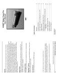
Horiba U-22XD Multi-Parameter
Water Quality Monitoring System
(1050R01 Horiba U-22.doc)
Missouri State University
and
Ozarks Environmental and Water
Resources Institute (OEWRI)
Prepared by: __________________________________
OEWRI Quality Assurance Coordinator
Date: _____________
Approved by: __________________________________
OEWRI Director
Date: _____________
ID: Horiba U-22
Revision: 1
September 2006
Page 2 of 14
Table of Contents
1
Identification of the test method ................................................................................. 3
2
Applicable matrix or matrices...................................................................................... 3
3
Detection Limit ............................................................................................................. 3
4
Scope of the test method ............................................................................................. 3
5
Summary of test method.............................................................................................. 3
6
Definitions ..................................................................................................................... 4
7
Interferences ................................................................................................................. 4
8
Health and safety .......................................................................................................... 4
9
Personnel qualifications .............................................................................................. 5
10
Equipment and supplies .............................................................................................. 5
11
Reagents and standards .............................................................................................. 5
12
Sample collection, preservation, shipment and storage ........................................... 6
13
Quality control .............................................................................................................. 6
14
Calibration and standardization .................................................................................. 6
15
Procedure ....................................................................................................................10
16
Data acquisition, calculations, and reporting ............................................................12
17
Computer hardware and software ..............................................................................13
18
Method performance ...................................................................................................13
19
Pollution prevention ....................................................................................................13
20
Data assessment and acceptable criteria for quality control measures..................13
21
Corrective actions for out-of-control or unacceptable data .....................................13
22
Waste management .....................................................................................................14
23
References ...................................................................................................................14
24
Tables, diagrams, flowcharts and validation data .....................................................14
ID: Horiba U-22
Revision: 1
September 2006
Page 3 of 14
1
Identification of the test method
Horiba U-22XD Multi-Parameter Water Quality Monitoring System
2
Applicable matrix or matrices
This instrument can be used for natural water samples.
3
Detection Limit
The operating ranges for this instrument are: temperature 0º to 55ºC, conductivity
0 to 9.99 S/m, Dissolved Oxygen (DO) 0 to 19.9 mg/L, pH 0 to 14 units, turbidity 0 to 800
NTU, and total dissolved solids (TDS) 0 to 65.0 g/L.
4
Scope of the test method
4.1
This procedure will be used as a field reference guide for the collection of water
quality analytes. Water temperature, conductivity, pH, dissolved oxygen, and
turbidity can be recorded using the Horiba U-22 Water Quality Monitoring
System.
4.2
5
The Horiba U-22 meter can also measure depth, oxidation-reduction potential
(ORP), total dissolved solids (TDS), salinity and seawater specific gravity. For
information on how to obtain these values refer to the Horiba user’s manual
which can be found on-line at http://www.wq.hii.horiba.com/uw22xd.htm and also
in the OEWRI office.
Summary of test method
5.1
The Horiba U-22 Water Quality Monitoring System uses a thermistor to measure
temperature. The thermistor also measures the change in electrical resistance
accompanying changes in temperature. The U-22 uses the temperature data in
conductivity temperature conversions, dissolved-oxygen temperature
compensation, and pH temperature compensation. Temperature influences the
conductivity of water. As the temperature increases, conductivity increases, due
to the increased movement of ions in the solution. Temperature changes in
water can have extreme biological effects. In general, as the temperature of
water increases, the amount of oxygen dissolved in the water decreases and
there is a tendency for the amount of pollutants to increase. The unit of
measurement for temperature is ºC (Celsius).
5.2
Conductivity is a measure of the ability of an aqueous solution to carry an electric
current. The conductivity of water depends upon the presence of ions (their total
concentration, mobility, valence, and relative concentrations) and on the
temperature of the solution. Adding electrolytes such as salts, acids, or bases to
pure water increases conductance. The U-22 uses the 4-electrode method to
determine conductivity. The conductivity of water is determined by measuring
the resistance of ion flow in between charged plates because conductivity is
inversely proportional to resistance. The Horiba reports conductivity as mS/cm
(milli Siemen / centimeter). Multiply this value by 1000 to report the conductivity
value as µS/cm.
ID: Horiba U-22
Revision: 1
September 2006
Page 4 of 14
6
5.3
The U-22 uses the membrane-electrode method for Dissolved Oxygen (DO). A
reduction reaction in the cathode is caused by oxygen diffusing through the
membrane of the sensor to create a current. This current is proportional to the
concentration of oxygen dissolved in water. DO is reported as mgDO/L.
5.4
Potential of hydrogen (pH) is a unit used to show the degree of acidity on a scale
of 0 to 14. The pH is a measure of the hydrogen ion (H+) activity in a solution.
Activity of the hydrogen ion (as moles/L) can be calculated as: pH = -log10[H+].
Or, [H+] = 1/10pH. The pH scale is logarithmic, so that a decrease of 1 pH unit is
equivalent to a ten fold increase in the hydrogen ion activity. For example, a
solution that has a pH of 4.0 is ten times more acidic than a solution with a pH of
5.0. The neutral point for pH is temperature dependent; at 25ºC pH 7.0 is
neutral, at 0ºC the neutral point is pH 7.5 and pH 6.5 is the neutral point at 60ºC
(Standard Methods, 2005). The glass-electrode method is used by the U-22.
The known pH of a reference solution is determined by using two electrodes, a
glass electrode and a reference electrode, and measuring the voltage (difference
in potential) generated between the two electrodes. The difference in pH
between solutions inside and outside the thin glass membrane creates
electromotive force in proportion to this difference in pH. The reporting unit is the
standard unit of pH (for example, 7.00 pH units).
5.5
Turbidity in water is caused by suspended and colloidal matter such as clay, silt,
finely divided organic and inorganic matter, and plankton and other microscopic
organisms. Turbidity is measured in the U-22 using the light-transmission
scattering method. The unit for turbidity is NTU (Nephelometric Turbidity Unit).
Definitions
6.1
Field duplicate: Two samples taken at the same time and place under identical
circumstances and that are treated identically throughout field and laboratory
procedures. Analysis of field duplicates indicates the precision associated with
sample collection, preservation, and storage as well as laboratory procedures.
6.2
Method detection limit (MDL) -- The lowest level at which an analyte can be
detected with 99 percent confidence that the analyte concentration is greater
than zero. The MDL is defined by the instrument manufacturer and is the lowest
value of the instrument’s detection range (see Table 1 in section 14).
7
Interferences
An improperly calibrated instrument can lead to erroneous results. See the
manufacturer’s instruction manual for proper calibration procedures and in sections 14
and 15. The U-22 probes should be clean prior to use to avoid contamination for any of
the analytes.
8
Health and safety
8.1
When wading in streams where water depths may be 1 meter deep or more,
wear a life preserver and/or remove hip boots or chest waders. Currents can
force wading field workers into deep water and water-filled boots can make
swimming difficult.
ID: Horiba U-22
Revision: 1
September 2006
Page 5 of 14
8.2
When walking through densely vegetated areas along streams, be sure to look
for and avoid toxic plants like poison ivy. Be sure to wear appropriate insect
repellent and protective clothing for protection from mosquitoes, chiggers, and
ticks. In addition, probe areas in your path with a walking stick to warn and
disperse poisonous snakes like the cottonmouth and copperhead, which may
inhabit riparian areas.
8.3
Be sure to clean up with bacteria disinfectant soap and water after wading in
streams. This is particularly important for streams that drain livestock areas,
sewage treatment plant effluents, and other obvious pollution sources. Under no
circumstances should you drink the water from any stream.
8.4
Protect from water borne illness by wearing protective gloves, avoid touching
eyes, nose and mouth and washing hands frequently with soap and water.
9
Personnel qualifications
Water parameters will be collected by Missouri State University (MSU) field
personnel who have received appropriate training from experienced personnel, prior
coursework, and field experience regarding the collection of water parameter data, and
who are familiar with all of MSU’s sample handling and labeling procedures and
appropriate SOPs..
10
Equipment and supplies
10.1 Model U-22 Water Quality Monitoring System, Horiba Instruments Inc., 17671
Armstrong, Irvine Industrial Center, Irvine, California, 92614, Telephone: 949250-4811, Fax : 949-250-0924, http://www.horiba.com
a. Main unit
b. Probe and cord
c. Carrying case
d. Spare parts kit
10.2
11
Water Quality Field Book, Pen
Reagents and standards
11.1 pH 4 Standard solution: Horiba model: 100-4, part number: 9003-0016-00 (500
mL bottle).
11.2
pH 7.00 Standard Buffer: Fisher Scientific. SB107-500.
11.3
pH internal reference solution: Horiba model: 330, part number: 9037-0052-00
(250 mL bottle).
11.4
DO probe Internal Solution: Horiba model: 305. Caution: contains Potassium
hydroxide.
11.5
Sodium sulfite: (for DO calibration) dissolve 12.5 g of Sodium sulfite with
deionized water. Dilute to 250mL with DI in a 250-mL volumetric flask.
ID: Horiba U-22
Revision: 1
September 2006
Page 6 of 14
11.6
Potassium chloride (KCl) solution: weigh 0.746 g of KCl into a 200 mL volumetric
flask. Dilute to 200 mL with DI. Final concentration is 667 mS/m (= 0.667 S/m).
11.7
Turbidity standard, 100 NTU: or other high value turbidity (40 – 100 NTU)
standard. Purchased form Fisher Scientific or other vendor.
11.8
Deionized water (DI)
12
Sample collection, preservation, shipment and storage
Water samples are not collected using this procedure. The analyses are
conducted in situ and only data are collected and stored in the instrument.
13
Quality control
13.1 Laboratory Reagent Blank (LRB): before leaving the laboratory, the analyst
should perform one measurement of deionized water. This operation will show
that the auto-calibration has been performed and that the unit is reading blanks
correctly.
14
13.2
Field Duplicates (FD): Two measurement readings taken at the same sampling
location. The results are compared after downloading the data. One FD will be
collected with every ten samples collected in the field.
13.3
After calibration, pH is checked against a NIST-traceable standard (pH = 7.00
units).
13.4
Annually, the Horiba thermistor is compared to a NIST certified thermometer.
The results are recorded in the Horiba instrument log book. A correction factor is
noted and applied to all data.
13.5
The DO calibration can be compared to a manual oxygen analysis, such as the
Winkler (see Standard Methods, 4500-O).
13.6
All calibration and quality control information is recorded in the instrument log
book.
Calibration and standardization
14.1 Specifications for the U-22 are listed in Table 1:
Table 1. Specifications for Horiba U-22
Parameter
Principle
Range
Repeatability
Temperature
Thermistor
0º - 55ºC
± 0.3ºC
Conductivity
4-electrode
0 - 9.9 S/m
± 1% / F.S.
Dissolved Oxygen
Diaphragm
0 - 19.9 mg/L
± 0.1 mg/L
ID: Horiba U-22
Revision: 1
September 2006
Page 7 of 14
0 – 14 pH units
± 0.05 units
0 – 800 NTU
± 5%
0 – 100 m
±3%
Conductivity conversion
0 – 65.0 g/L
± 2 g/L
Salinity
Conductivity conversion
0 – 4%
± 0.3%
ORP
Platinum electrode
± 1999 mV
± 5 mV
0 – 50 σt
± 2 σt
pH
Glass electrode
Turbidity
Penetration and Scattering
Depth
Pressure method
Total Dissolved Solids
Seawater specific gravity Conductivity conversion
14.2
14.3
To increase accuracy for conductivity, the U-22 uses the 4-electrode method that
reduces the amount of polarization that occurs on the electrode plates. The U-22
uses an automatic temperature conversion function to calculate conductivity at
25ºC at a temperature coefficient of 2%/ºC, based on the measured value of the
temperature. See equation 1.
Equation 1:
L25 = Lt / {1 + 0.02(t-25)}
Where:
L25 = Conductivity of solution converted to 25ºC (value displayed
on U-22),
t = Temperature of solution at time of measurement (ºC), and
Lt = Conductivity of solution at t (ºC)
Calibrating the U-22: There are two types of calibration for the U-22, an AUTO
calibration and a Manual (or Span) calibration. For routine operation, the AUTO
calibration will result in sufficient accuracy. The Manual calibration should be
performed after any maintenance to the instrument.
a.
AUTO calibration
1.
In this mode, the pH, COND, and TURB sensors are calibrated in
the pH 4 standard solution, and the DO and DEP sensors are
calibrated in the atmosphere simultaneously.
2.
Fill the calibration beaker to the marked line with the pH 4
standard solution (Horiba 100-4).
3.
Immerse the sensor into the beaker and press the CAL key.
4.
AUTO and CAL appear on the instrument screen. The lower
cursor should be on the AUTO sub-mode; if it is not, then use the
MODE key to move the lower cursor to AUTO.
5.
Press the ENT key to start AUTO calibration. The readout will
show CAL. Wait about a minute and the upper cursor will
gradually move across the auto-calibration parameters one-byone: pH, COND, TURB, and DO. The upper cursor will blink while
the auto-calibration is taking place.
6.
When the calibration is complete, the readout will briefly show
END and then press the MEAS key to switch to the MEAS mode.
ID: Horiba U-22
Revision: 1
September 2006
Page 8 of 14
7.
b.
If the unit shows an error message, an auto-calibration error has
occurred. Press the CLR key to cancel the error code and re-start
the auto-calibration by pressing the ENT key.
Manual or Span Calibration
pH Calibration
1.
Wash the sensor two or three times with DI.
2.
Immerse the sensor into 7.00 pH buffer in the calibration beaker
3.
Press the CAL key twice in the pH Measurement mode.
4.
MAN, ZERO and CAL light up
5.
Use the UP/DOWN (▲ ▼) keys to input the temperature adjusted
value for the pH 7.00 standard.
6.
When the indicated value has stabilized, DATA IN lights up and
the calibration finishes.
7.
Wash the sensor two or three times with DI.
8.
Immerse the sensor in 4.00 pH buffer in the calibration beaker.
9.
Press the CAL key to make sure that the instrument is in the
Manual Span Calibration mode: MAN, SPAN and CAL light up.
10.
Use the UP/DOWN (▲ ▼) keys to set the value for the pH 4.00
solution at the measurement temperature.
11.
Press the ENT key. Manual span calibration starts.
12.
When the indicated value has stabilized, DATA IN lights up and
the calibration has finished.
13.
Record that the instrument has been calibrated for pH in the
Horiba instrument log book.
Conductivity Calibration
1.
Prepare the calibration solution: weigh 0.746 g of KCl into a 200
mL volumetric flask. Dilute to 200 mL with DI. Final concentration
is 667 mS/m (= 0.667 S/m).
2.
Wash the conductivity sensor two or three times with DI.
3.
Completely remove the water on the sensor and calibrate the
sensor in air.
4.
Press the CAL key twice in the COND measurement mode.
MAN, ZERO and CAL light up
5.
Use the UP/DOWN (▲ ▼) keys to set the value at 0.0.
6.
Immerse the sensor into the calibration solution in the calibration
beaker.
7.
Press the CAL key twice. MAN, SPAN and CAL light up
8.
Use the UP/DOWN (▲ ▼) keys to set the standard solution value
(i.e., 0.667 S/m). The sensor will automatically identify the
calibration solution and the relevant calibration range is displayed
(i.e., r1, r2, or r3 - see manual).
9.
Press the ENT key, the manual calibration starts.
10.
When the indicated value has stabilized, DATA IN lights up and
the calibration finishes.
11.
Record that the instrument has been calibrated for conductivity in
the Horiba instrument log book.
ID: Horiba U-22
Revision: 1
September 2006
Page 9 of 14
Turbidity Calibration
1.
Make sure that the TURB sensor is clean.
2.
Immerse the sensor in DI (0 NTU standard) in the calibration
beaker.
3.
Press the CAL key twice in the TURB measurement mode. MAN,
ZERO and CAL light up.
4.
Use the UP/DOWN (▲ ▼) keys to set the value at 0.0.
5.
Press the ENT key, the manual calibration starts.
6.
Immerse the TURB sensor into the calibration beaker containing
the 100 NTU standard.
7.
Press the CAL key twice. MAN, SPAN and CAL light up.
8.
Use the UP/DOWN (▲ ▼) keys to set the standard solution value
at 100.
9.
Press the ENT key, the manual calibration starts.
10.
When the indicated value has stabilized, DATA IN lights up and
the calibration finishes.
11.
Record that the instrument has been calibrated for turbidity in the
Horiba instrument log book.
DO Calibration
1.
Prepare the zero calibration solution: Add 50 g of sodium sulfite to
1 L of DI and mix to dissolve the sodium sulfite.
2.
Immerse the sensor into the 0 DO solution in a flask large enough
to accept the sensor (not the calibration beaker).
3.
Press the CAL key twice in the DO measurement mode. MAN,
ZERO and CAL light up
4.
Use the UP/DOWN (▲ ▼) keys to set the value at 0.0.
5.
Press the ENT key. When the indicated value has stabilized,
DATA IN lights up and the calibration is finished.
6.
Prepare the air-saturated water solution: feed air into a large
beaker or bucket of DI using a pneumatic pump. Continue
supplying air for several minutes to ensure saturation.
7.
Press the CAL key twice. MAN, SPAN and CAL light up.
8.
Using the temperature displayed and the table (ISO5814 table) on
page 56 of the manual, determine the amount of DO in the water.
9.
Use the UP/DOWN (▲ ▼) keys to set the standard solution value
at from the table (for example, at 25ºC, 8.42 mgDO/L will be in a
saturated water sample).
10.
Press the ENT key. The manual span calibration starts.
11.
When the indicated value has stabilized, DATA IN lights up and
the calibration finishes.
12.
Record that the instrument has been calibrated for DO in the
Horiba instrument log book.
Temperature Calibration
1.
Press the CAL key in the TEMP measurement mode
ID: Horiba U-22
Revision: 1
September 2006
Page 10 of 14
2.
3.
4.
5.
6.
15
Immerse the sensor in water at a known temperature (use a NISTtraceable thermometer to determine the known temperature).
Use the UP/DOWN (▲ ▼) keys to set the value at this
temperature.
Press the ENT key. The manual calibration starts.
When the indicated value has stabilized, DATA IN lights up and
the calibration finishes.
Record that the instrument has been calibrated for temperature in
the Horiba instrument log book.
Procedure
15.1 Measuring Water Parameters
a.
Turn the power on and gently place the probe into the water body to be
sampled. Never drop or throw the probe into the water body. Each of the
probes is sensitive to extremes. This includes impact and heat (do not
leave the probe inside a vehicle with the windows closed or in prolonged
direct sunlight).
15.2
b.
All parameters should be taken from the flowing portion of the stream or if
in a pool at least one foot from shore and at least 6 inches below the
surface.
c.
The dissolved oxygen parameter should be taken from a flowing portion
of the stream if possible, but should avoid areas of turbulence where
atmospheric gases may be entrained in the water column. In addition a
dissolved oxygen measurement should be made 6 inches below the
surface and 6 inches above the bottom or at depth of 4 feet, whichever is
less. All parameters are measured simultaneously.
d.
To get a uniform reading, slowly move the probe up and down to circulate
the water through it. Wait for the readout to stabilize while doing this.
e.
Make sure that MAN is displayed in the Measurement mode screen.
Press the ENT key. Data storage starts. DATA IN and the data number
are displayed on the screen. The measured values are displayed in order
at about 0.5 second intervals.
f.
Press the [MEAS] key to move to the various parameters. If desired,
manually record pH (pH), conductivity (COND), turbidity (TURB),
dissolved oxygen (DO), temperature (TEMP), site ID and date for each
site in the field notebook.
Data Storage
a.
The U-22 can store up to 2880 sets of data of the values measured for
each of the parameters: pH, COND, TURB, DO, and TEMP.
b.
When the readout stabilizes on a value, press the ENT key. This will
automatically input the parameters for the measurement into memory.
ID: Horiba U-22
Revision: 1
September 2006
Page 11 of 14
c.
The readout will show the Data Set number first for about 2 seconds.
Then each parameter is automatically read into memory, one-by-one.
The upper cursor skips along to show this.
d.
The upper cursor then returns to pH, with the U-22 in measure mode.
e.
The unit can be turned off between sites to preserve battery strength. Fill
the storage cup with stream water if necessary to keep the probes wet
between sites. DI can be used to clean the probes between sites.
15.3
Maintenance
a.
Turn OFF the power.
b.
Wash the probe thoroughly with tap water. Be sure to flush off all of
sample solution from the probe.
c.
When storing the U-22 for brief periods of a week or less, fill the
protective rubber cap with distilled water and fit the probe over it.
d.
The pH sensor must always be kept moist. For longer storage, remove
the sensor from the sensor probe and check that the internal solution
replenishment port is closed. Then attach a seal to the liquid junction and
attach rubber caps. Also remove the DO sensor and set the short socket
and store in a cool, dark place. Recharge the reference sensor with
reference solution about once every 2 months.
1.
Remove the liquid-junction rubber cap from the reference sensor
and pour out the old solution.
2.
Fill the reference sensor completely with new reference solution.
Make sure that there are no air bubbles.
3.
Replace the liquid-junction rubber cap.
4.
Carefully wash off all excess reference solution from the probe.
5.
Record the date of the reference sensor recharge in the
instrument log book.
e.
See Horiba manual for maintenance procedures for DO sensor
diaphragm replacement (page 89).
15.5
Automatic Data Storage
a. Measured values are stored automatically at constant time intervals.
b. See the Horiba user’s manual for details on how to use this function.
c. There are three options that can be set for automatic data storage.
Waiting time for initial data storage
Data storage interval, that is, time between data storage measurements
Data storage measurement period. The time period between the first and
last data storage measurements.
d. Data retrieval is by the same process as listed below (section 16.1 and 16.2)
for manual data storage.
ID: Horiba U-22
Revision: 1
September 2006
Page 12 of 14
16
Data acquisition, calculations, and reporting
16.1 Horiba U-22XD Data Download Procedure:
Note: The download cable and interface software are installed on GGP-111990
in Temple 125. If “Horiba U-20” icon does not appear on your desktop when
logged onto that computer, navigate to C:/U20 and double-click on U20System.exe to start program at step d. below.
a. Install data link unit on back of Horiba. Attach cable to port on data link unit.
b. Simultaneously press SET and POWER buttons on Horiba (to put unit into
PC mode). PC 232C is shown on the display in this mode.
c. Open Horiba U-20 program (use above procedure if necessary).
d. Choose SENSOR>OPEN DATA to access all data files saved on unit.
e. When data has finished loading to screen (may take several minutes), select
desired records by holding shift key and clicking data numbers. Press
SELECT on download window.
f.
Data will appear in Data Screen. Individual records may be examined in this
screen if desired. Click DATA>CLOSE to return to Main Screen.
g. On Main Screen, click FILE>SAVE AS and choose a file name and
destination. Filename should include project name and date. Destination
could be Desktop, floppy disk, zip disk or flash drive. If you save on the
desktop and you will have many Horiba files, please make a folder for your
files.
h. After saving data, close HoribaU-20 program, turn off Horiba U-22XD unit and
disengage data cable. If necessary follow Horiba cleanup procedures.
16.2
Horiba Data Handling:
Note: The Horiba data files are saved as .csv. Be sure to set Excel to look for
“All Files” to find it.
a. Open data file in Excel. Note that Horiba numbers are not included as a field
and the only identifiers, other than record order, are DATE and TIME.
b. Some fields are blank and filled with “---------“, delete these. Other fields are
not pertinent (DEP, SAL, σt) and others may not be important for your uses;
delete these also.
c. Add fields for SITE, and any other information you need to associate with the
water quality data.
d. Save As an Excel (.xls) file. (Make sure that the filename includes project
and date or some other unique identifier: a desktop cluttered with Horiba1.xls
ID: Horiba U-22
Revision: 1
September 2006
Page 13 of 14
files will become confusing very quickly) This will leave you with two files; the
original .csv file and the new and updated .xls file.
e. If necessary, e-mail the file to yourself if it’s saved on the desktop.
17
Computer hardware and software
17.1 The Horiba U-22 has internal software and also software for data transfer to a
PC.
17.2
Microsoft Excel is used for recording and reviewing the final data from the
Horiba.
17.3
This document is created using Microsoft Word. The Word file name for this
SOP is: 1050R01 Horiba U-22.doc.
18
Method performance
There are no published method performance data for this method.
19
Pollution prevention
All wastes from these procedures shall be collected and disposed of according to
existing waste policies within the MSU College of Natural and Applied Sciences.
Volumes of reagents made should mirror the number of samples being analyzed. These
adjustments should be made to reduce waste.
20
Data assessment and acceptable criteria for quality control measures
20.1 The analyst should review all data for correctness.
21
20.2
Precision values are calculated for pairs of duplicate analyses.
20.3
The desired precision is ± 20%
20.4
The completed Excel spreadsheet is reviewed by the analyst’s supervisor or the
OEWRI QA coordinator
Corrective actions for out-of-control or unacceptable data
21.1 The results for precision and blank data are compared to the acceptable values
for this analysis; ± 20% and 0 for all analytes, respectively.
21.2
If data are unacceptable for any reason, the analyst should review their analytical
technique prior to conducting this analysis again.
21.3
The instrument may require trouble shooting techniques if the data are
unacceptable
a.
Clean the probes
b.
Perform maintenance procedures as outlined in manual
c.
Replace defective sensors
d.
Send the instrument to the manufacturer for repair.
ID: Horiba U-22
Revision: 1
September 2006
Page 14 of 14
22
Waste management
The wastes generated in this method are not hazardous. The quantities are very
small and can be discarded in the laboratory sink.
23
References
23.1 Operation Manual, Horiba Multi-parameter Water Quality Monitoring System, U22XD. 2001. Scientific and Water Quality, 17671 Armstrong Ave., Irvine, CA
USA 92614
23.2
24
Standard Methods for the Examination of Water and Wastewater. 2005. 21st
Edition. APHA, AWWA, WEF Publishers.
Tables, diagrams, flowcharts and validation data
There are no tables, diagrams, flowcharts or validation data for this method