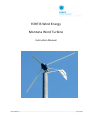
1
FORTIS Wind Energy Montana Wind Turbine Instruction Manual ___________________________________________________________________________________________________________________ Manual Montana Page 1 of 48 No part of this document may be reproduced or transmitted in any form or by any means, electronic or mechanical, including photocopying and recording, for any purpose without the express written permission of FORTIS WIND ENERGY. FORTIS WIND ENERGY reserves the right to make changes to any and all parts of the documentation, at any time, without obligation to notify any person or entity of such changes. © Copyright 2013, FORTIS all rights reserved. Fortis Wind BV 9751 AC Haren The Netherlands ___________________________________________________________________________________________________________________ Manual Montana Page 2 of 48 § Table of Contents § Index: Page 1 Introduction 6 2 Assembling Power head 7 2.1 Frame/generator 7 2.2 Rotor blades / Hub 7 2.3 Tail 8 2.4 High-Wind speed Protection 8 2.5 Mast top 8 2.6 Nose cone 8 3 Instructions Mast 9 3.1 Producing a Mast yourself 9 3.2 Foundations 10 3.3 Installation preparations 10 4 Electric Installations: 13 4.1 Transmission lines 13 4.2 Voltage control / dumpload 13 4.3 Grid connection 14 4.4 Batteries 14 5 Final assembly system/electronics: 15 6 Erecting the turbine in the upright position: 17 6.1 Safety first 17 6.2 Conditions during installation 17 ___________________________________________________________________________________________________________________ Manual Montana Page 3 of 48 6.3 The installation(erection) procedure 18 6.4 Guy wire tensioning 18 6.4.1 Determining the proper frequency of the cable 19 6.4.2 How to oscillate the cable 19 6.4.3 Procedure of tensioning the cable 20 6.4.4 Cautions, Hints and Suggestions 20 6.5 Start-up procedure 21 7 Appendix: 7.1 Torque specifications 23 7.2 Required tools 23 7.3 Technical data Montana (5kW) 24 7.4 Power curve Montana 25 7.5 Maintenance / checklist 26 7.6 Foundation blocks for guyed towers 27 7.7 Anchors and concrete specifications 28 7.8 Voltage drops Fortis Montana 400V wind turbine 29 7.9 Voltage drops Fortis Montana 48V wind turbine 29 8.0 Voltage drops Fortis Montana 120V wind turbine 29 9.0 Tail Assembly 30 10 Plug and socket in tower base 31 11.0 Detail chain and spring between tail and support frame 32 11.1 Terminal box at backside of generator 32 12 Gin pole and winch 33 13 Drawings guyed tower 35 ___________________________________________________________________________________________________________________ Manual Montana Page 4 of 48 13.1 Drawings guyed tower 36 14 Part numbers of Montana 37 14.1 Part number list 38 15 Brake Switch 5000/12 39 16 Feed-in Inverter GFI-5K 40 17 Electrical scheme for grid connected 41 18 Electrical scheme for stand alone and battery charging 42 19 Trouble shooting list 43 20 Safety and control procedures 45 21 Declaration of Conformity 47 ___________________________________________________________________________________________________________________ Manual Montana Page 5 of 48 1. Introduction Thank you for choosing this FORTIS energy systems. Your choice means proven reliability, no maintenance costs (only a regular check is recommended) and the convenience of an independent power supply. FORTIS wind turbines are in operation all over the world and can withstand almost every environment imaginable. Even arctic expeditions have benefited from the reliable power the FORTIS wind turbine produces. FORTIS tests their systems under the worst possible weather conditions. FORTIS wind turbines are installed at all over the earth Therefore the FORTIS products are designed on such a way that they can be installed and erected successfully with a minimum of tools and technical know-how. Also unskilled people are capable of maintaining the system with a minimum of tools and knowledge. A FORTIS-system is almost always composed of various components: the wind turbine itself is only one component of this system. We can supply controllers for battery charging and for grid connection. For hybrid systems, controllers are available to couple a photovoltaic solar generator or to a diesel or petrol generator together to a FORTIS Wind turbine. In other words, the possibilities with an FORTIS wind turbine are endless in the sense that they can be adapted to suit almost every conceivable application. Sincerely, Fortis Wind Energy Important security notice This Instruction Manual contains important operational guidelines and security considerations that require your attention. Before installation, it is essential that the user first studies this user's manual in detail and keeps in mind the safety matters that need attention. During user installation and operation one must refer to this handbook's documentation. If you are unfamiliar with installation as shown below, DO NOT CONTINUE and let a qualified Technical Engineer proceed with correct installation. Failure to comply with the guidelines and instructions will void your warranty. Do not change anything of the wind turbine parts or do not paint the blades. If you do so you lose the right of warrantee. Any change can have effect in the behaviour of the wind turbine. ___________________________________________________________________________________________________________________ Manual Montana Page 6 of 48 2. Assembling the power head The FORTIS MONTANA (5 kW) power head consists of the following parts; Frame/generator/mast adapter Rotor blades/hub Tail with tail vane 2.1 Frame/generator When you first open the crate, check the contents carefully starting with the generator and its supportframe. First make a visual check to determine any existing scratches, dents or cracks. Then rotate the generator by hand. This must rotate smoothly (<5.0N/m). If it does not, check whether there is no shortcircuit in one of the phases. (out coming wires might be connected somehow) Normally the generator is already attached to the support frame with a specified torque (appendix 7.1) so there is no need to tighten the eight M12 bolts. The power head is bolted to the crate it is transported in, before you undo these bolts, remove all other components inside the crate. We advise to wait with unpacking the power head till its mast is ready to receive it. The power head can then be moved straight from the crate on to the mast. 2.2 Rotor blades/hub The large cardboard box contains the rotor blades and parts of the tail frame. Sometimes also the dumpload is packed with the rotorblades. Unpack the rotor blades and make a visual check for any existing cracks or scratches. When nothing is visible at all, the blades can be mounted between the two hub plates with the 9 x M12 bolts with self locking nuts. Every single blade has its unique fit to the hub, and in addition to this the blades are marked with "dots" that correspond with "dots" on the hub. The flat side of the blades should face the wind as is the front side of the hub. WARNING Be careful with assembling the 9 x M12 bolts. The bolts fits very narrow in the hols. For assembling turn the bolts only into the holes. Don’t use a hammer or drill the holes. Only in this way the rotor blades get the same position when they where balanced in the factory. Be careful with any damage to the thread to the bolts because it can give problems when you fit the nuts to the bolts. Stainless steel in sensitive for damaged thread. ___________________________________________________________________________________________________________________ Manual Montana Page 7 of 48 2.3 Tail The tail assembly is composed of 7 parts: the tail vane, the upper section and 5 steel bars. The lower section is already assembled to the frame. The steel bars are packed with the rotorblades. The tail vane with tail upper section and steel bars can be assembled with M8 bolts according the pictures on chapter 9.0 Tail Assembly and appendix 7.1 Torque specifications. The complete tail can be assembled to the frame by 2 x 2 M10 bolts. There is only one way to assemble the tail parts. In another way the pieces does not fit. The chain, which is already connected to the support frame, must be connected to the tail with a D-shackle. Make sure the stainless steel spring is mounted between the middle of the chain and the support frame. Don’t forget the split pins (cotter pins) to secure the nuts of the D-shackle. 2.4 High-Wind speed Protection (Side Furling) The High-Wind speed Protection system will protect the wind turbine automatically during high wind speeds. When furled, the rotor will turn away from the wind direction. When the rotor speed is reduced, the power output of the wind turbine will be significantly reduced. Side Furling is an easy method to provide high wind speed protection. It is based on a basic physical relationship between aerodynamics, rotor, gravity, the specially designed tail shape and weight balance of the Montana. Side Furling is completely passive and very reliable. 2.5 Mast top The mast top is fit into the support frame of MONTANA (5 kW) wind turbine. Do not remove the mast top from the frame. Inside are Teflon coated vertical thrust bearing and radial glider bearings. Further they are greased with copper grease. Before you bolt it on top of the mast, make sure that it fits well in the support frame and can be rotated by hand in this position. 2.6 Nose cone Further you will find in the packing, a box with the nose cone and all the bolts and nuts for assembling. Also the voltage controller with dump load is packed with the generator. In some cases the dumpload is packed in the box with the rotor blades. ___________________________________________________________________________________________________________________ Manual Montana Page 8 of 48 WARNING When any parts of the wind Turbine show damage that might have occurred during transportation, inform your local supplier or FORTIS directly about this. If you do not report such damage or the turbine is already in operation, you lose the right to your warranty ! 3 Instructions Mast 3.1 3.2 3.3 Producing a Mast yourself Foundations Installation preparations 3.1 Producing a mast yourself Producing a mast for your FORTIS wind turbine is relatively simple. Various constructions are possible but in most cases a steel tubular mast with guy wires is used. It is also possible to use wooden poles, free standing steel tubular masts or free standing lattice masts. Even concrete masts are a possible option. However, before you start to construct your mast, you have to consider where you are going to place the wind turbine and mast. For a good performance, it is necessary to install the wind turbine in such a way that the wind has an uninterrupted flow from all directions to the wind-rotor. Any obstructions such as trees, hills or buildings, even if they are somewhat lower than the wind-rotor, will cause turbulent air currents to arise which seriously decrease the generator output. Turbulent air has lost a large part of its original power and continually shifts from one direction to another, also upwards and downwards. This causes the wind turbine to vibrate to some extent. All of these factors should be considered when selecting a satisfactory location for the wind turbine. The higher the wind turbine is situated the better since the air currents are smoother and steadier further from the ground. For a good operation, the wind turbine should be mounted at least 5 metres above any obstruction within 200 metres! In order to keep electrical losses caused by long transmission lines to a minimum: Install the wind turbine as close to the application as possible without disturbing an unobstructed sweep from the wind. The dimensions of transmission lines are described under the chapter heading"Transmission lines 4.1". ___________________________________________________________________________________________________________________ Manual Montana Page 9 of 48 In most cases FORTIS advises the use of the guyed steel tubular mast as it is inexpensive, easy to build, easy to erect and FORTIS can provide all the required calculations. These calculations can be very important when planning permission has to be obtained. The drawings for a guyed steel tubular mast are provided in this manual. The masts are designed according to a modular system with 6m modules, guyed every 6m. (Appendix 13). 3.2 Foundations As there is such a wide variety of masts possible, we only describe here the foundations for the standard guyed steel tubular mast according to the standard FORTIS design. There are three ways to make a proper foundation for the mast and guy wires: 1] The first type of foundation is for very soft and unstable ground: for this type, concrete blocks of a certain weight have to be used. Drawings for this type of foundation are provided in appendix 7.6 / 7.7. 2] The second type of foundation is for rocky ground: this type requires the use of rock-bolt's for the tower and the guy wires. Make sure that the rocks are heavy enough. FORTIS can provide and specify the rock-bolts on request. The size and weight of the rocks must be about the same as the concrete blocks described in the foundation drawings. 3] The third type of foundation is for medium soft but stable ground: for the guy wires, earth-screwanchors are used and for the mast, a small concrete block will be sufficient. The earth-screw-anchors can be specified and provided by FORTIS. The concrete block is the same as in appendix 7.6 / 7.7 or a standard block for roads can be used in the size of 2 x 2 x 0,12 cm. The base plate can be fit with chemical bolts. 3.3 Installation preparations Before the mast is placed in a horizontal position, bolted to the base-plate, make sure the mast will be lifted towards the main wind direction. Lift and support the top of the mast in such a way that it is possible to slide the support frame over the mast top. However, before you do this, it is necessary to pull the wires through the mast. For your FORTIS MONTANA (5kW) machine, 3 flexible wires of 6 or 10 mm² will be sufficient in most cases. Only for 48V systems 10 mm² or 16 mm² is required. They must be pulled through the support frame first, and then through the mast. Now you can slide the support frame over the mast top. The connecting wires must not get stuck anywhere on any part of the wind turbine. Make sure the three wires can move and rotate freely inside the mast. Any possible problems in this area can cause a short circuit. ___________________________________________________________________________________________________________________ Manual Montana Page 10 of 48 On top of the support frame, a knot or loop in the connecting wires must act as pull relief. Use three wires with the same colour to indicate the three similar phases. These three wires must be connected to the three wires coming from the generator, the connector block can be found in the white box that is attached to the generator. The order of connection is not important since all three lines are equal at both sides. At the basement of the tower the 3 wires are connected to a plug and socket. This plug and socket can be used to retwist the cable in the tower. In some lace the wind can change from direction regular and the turbine rotated 360 degrees. When you have installed the turbine check every month the twisting. If you did not retwist after 6 month you can check the wires ones a year. If the cables are twisted disconnect the plug and socket when the wind speed is very low. Retwist the cables and plug in again It take only a few minutes. WARNING Never disconnect the plug and socket at moderate or high wind speeds. The open circuit voltage can reach to a very high level and results in damage of the electronics when assembling the plug and socket. The lower section of the tail with spindle is assembled to the frame. There is no need to change it but in case you have to replace it follow the procedure. The tail uses a stainless steel pin as spindle. This is fit to the frame. Note in which way the spindle shaft is assembled into the frame. The pin must slide into the tubular section of the tail frame where it passes through two Teflon bearings. When assembling the lower tail section to the frame, you put first the top of the spindle shaft into the top frame section and second the lower part. Note that before you put the spindle shaft in the lower part of the frame you put the Teflon ring around the spindle. The Teflon ring is the bearing surface which has to cope with the full weight of the tail. In principle, the tail bearings should not need any additional lubrication; however, applying grease extends the life of the bearings to some extent. The spindle is fixed with a M12 bolt with locking rings at the bottom of the frame and a self locking nut at the top. The chain, which is already connected to the support frame, must be connected to the tail with a D-shackle. Make sure the stainless steel spring is mounted between the middle of the chain and the support frame. Don’t forget the split pins (cotter pins) to secure the nuts of the D-shackle. Next to install are the rotor blades: the assembly of rotor blades (3) and 2 hub plates are bolted together with the 9 x M12 bolts. Hub plates ___________________________________________________________________________________________________________________ Manual Montana Page 11 of 48 The hub plates are marked with 1, 2 or 3 which is corresponding with blade number. One hub plate is the front which has connections for the nose cone. The other hub plate can be used only in one position. Don’t drill the holes because the blades get only in this way in the right position and therefore are balanced. Because the bolts are made of stainless steel you must be careful not to damage the threat. If the threat of the bolt is damaged it is impossible to get the nut on it. After the 3 blades are assembled together you can fix the complete rotor to the generator. The remaining 9 holes of 15 mm corresponds with the 9 x M14 bolts on the generator. There are 9 x M14 nuts with norlock washers to secure the nut of getting free. Finally assemble the nose cone with 3 bolts. The next stage involves the guy wires: a standard FORTIS MONTANA (5kW) mast according to FORTIS specifications is guyed every 6m, in four directions. Make a rough calculation of the length of each individual guy wire and then connect it to the mast and to its foundation. The only guy wire that cannot be connected is the one directly opposite the direction in which the mast is pointing. This guy wire should be connected when the mast is in the upright position. All guy wires are connected to the mast with a bow shackle, to the foundation with a rigging screw and twin cable clamps. Both cable clamps must be fully tightened before lifting the mast. ___________________________________________________________________________________________________________________ Manual Montana Page 12 of 48 4 Electric Installations 4.1 4.2 4.3 4.4 Transmission lines Voltage control/ dumpload Grid connection Batteries 4.1 Transmission lines The FORTIS MONTANA (5kW) generator is a 3 phase generator and 3 electric wires are needed to connect the generator with the rectifier bridge which is inside the voltage control box. The maximum rectified current is 150 ADC and peak voltage is 600 VDC. The working temperature of the components is - 40°C to + 50°C. The electric wires have to be flexible and should not consist of a single solid copper core. Furthermore, the isolation wrapping of the wires should be UV-resistant (PVC-isolation cannot stand UV light). Prevent the damaging of the electric wires by sharp edges. Any damage to the electric wires will lead to short-circuiting and the rotor will stop rotating, or even worse, the rectifier bridge might be destroyed because of too many amperes. Never let the wires hang with their full weight on the cable terminals. If the cable is long and heavy use steel wire inside the tower and tape the electric wires to this steel wire every 4 –6 m. For the wire-gauge see the chapter 7.8 -8.0. 4.2 Voltage control / dump load (battery charging system) The electronic voltage control prevents over-charging of the batteries. When the batteries reach a threshold value, the current from the generator is proportionally directed to a dump load. The dump load can either be a coil for water heating or for air heating. The box of the voltage control unit is made according to international standard IP 44 and is not 100% weather resistant. Every voltage controller is supplied with an air-heating coil which functions as dump load. Water heating is optional. To prevent any problems with heat dissipation, mount the dump load above or at some distance away from the controller. It is advisable to mount the controller as close to the batteries as possible to minimize electrical losses. When the controller is housed in the same room as the batteries and dump load, the room must be well ventilated. There are two possible voltage controller types for the FORTIS MONTANA (5kW); - 1] IN 400V_15A Over Voltage controller / Dump load for Grid-Connected - 2] IN 48V_100A Over Voltage controller / Battery charger / Dump load for Off_Grid Note: Detail Information see Manual Voltage Controller 48V-100A or IN 400V_15A. ___________________________________________________________________________________________________________________ Manual Montana Page 13 of 48 4.2.1 External Brake Resistor Montana Dump load: Connection: Cable type: Length: Inverter type: Battery charging Single Phase 48V 4x 1850W / 56V Parallel 230V/50Hz 1x 5 kW/33 Ohm IN_48V_100A EMC Shielded Max. 2 m GFI-5K WARNING The brake-switch short circuit the generator and will bring the rotor stop rotating up to wind speeds of 8 - 9 m/sec. Never let the brake switch on for more than ten minutes if the rotor does not stop because of high wind speeds. The generator can be overheated and destroyed. 4.3 Grid connection Grid connection is one of many options with an FORTIS system. In a grid-connected FORTIS MONTANA (5kW) system, the voltage controller IN 400V_15A can be used in combination with an active brake switch and a grid-link inverter (Aeocon or SMA). The voltage controller is needed to protect the inverter against peak voltages when the load is disconnected. At present we use a one housing solution by a GFI5K grid tie inverter. 4.4 Batteries Batteries need to be kept in a place with sufficient ventilation and no risk of freezing. Charged batteries can stand temperatures of up to minus 20°C, but uncharged batteries cannot withstand frost at all. Place the batteries underneath the voltage control in the same room if possible as this minimizes energy loss in the wires. A battery is normally 12 V so you need two batteries connected in series for 24 VDC or 4 for 48V or 10 for 120VDC. Connect the minus terminal of one battery with the plus terminal of the other battery. The remaining terminals are the plus and minus of the battery group. For an FORTIS Montana 24V we advise a minimum battery capacity of 1000 Ah (C= 10 h), but a capacity of 2000 Ah is even better. For lead/acid batteries the charging/discharging current should not exceed 20% of the capacity (preferable 10%). ___________________________________________________________________________________________________________________ Manual Montana Page 14 of 48 5. Final assembly of system / electronics When mounting the voltage controller IN 400V_15A (Grid Connected), it is very important to choose a wall or surface which is non-conductive. Cooling blocks are mounted on both sides of the controller to cool the rectifier bridge and the MOSFET's of the electronic part. When the wind turbine is operating at full power, there is a heat generated in these blocks. The dumpload can get very hot. Both controller and dumpload should therefore be mounted in such a way that the risk of getting scorched is minimal. The wires of the dumpload must be connected to the two contacts in the middle of the contact rail. The dumpload is not sensitive to plus and minus, so the order of connection is not important. The same applies for connecting the three phases of the generator: these must be connected to the three contacts on the left of the contact rail. Again, the order in which they are connected is unimportant. The last component to connect is the consumption circuit. The consumption circuit can either be a battery-bank, an inverter for grid connection or a Pump controller for water pumping. The contact rail has four terminals, on the right side, for the consumption circuit: two plus terminals and two minus terminals. Terminal connection IN 400V_15A (Grid Connected) Connect the metal casing to ground, 2 free “PE” terminals are available Connect the ballast resistor to the terminals “R1”, R2” and its case and cable shielding to the terminal “PE” Connect the DC-input of the grid inverter to the terminals “+” (gray), “-“ (blue) Connect the 3 phases of the generator to the terminals “L1”, “L2”, “L3” Terminal connection IN 48V_100A (battery charging) Connect the metal casing to ground, 2 free “PE” terminals are available Connect the 4 ballast resistors in parallel and the cases and cable shielding to the “Ballast” terminals “R1” (gray), R2” (gray), and “PE” (green/yellow) Connect the battery to the terminals “+” (gray), “-“ (blue) Connect the 3 phases of the generator to the terminals “L1” (gray), “L2” (gray), “L3” (gray) ___________________________________________________________________________________________________________________ Manual Montana Page 15 of 48 IMPORTANT! There is, however, a specific sequence in which all the above mentioned connections must be made. This is very important as if the connections are not made in this order, the generator or controller can be damaged during the installation procedure. 1] The brake switch has to be set on STOP 2] The dump load must always be the first component to be connected 3] The consumption circuit or inverters must always be the next component to be connected; beware of the difference between + and 4] The 3 wires of the generator are the next component to be connected 5] The batteries are the last component to be connected WARNING Be aware that step 1 and 2 are made properly before you start with step 3 and 4. If the generator has been connected first it is possible that a high voltage is generated which can damage the transistors. Be also aware of static electricity on your clothes or wires because they can damage the transistors too. Before the wind turbine is erected and during the process of erection the three phases of the generator should be short-circuited. If an IN-controller and active brake switch is used, this can be done by using the RED STOP button or the selector switch into position 2; short circuit. Any other (temporary) way of short-circuiting the three phases is allowed. It is not necessary to disconnect the batteries as they are protected from short-circuiting by the rectifier bridge. In addition to this, the batteries and any other consumption circuit should be properly fused. FORTIS advises to fuse all other consumption circuits in accord with their specifications as required. Check that all your connections are tightly and correctly connected. WARNING Never connect the wires from the generator to the controller when the wind turbine is in operation. The open circuit voltage can be 10x the nominal voltage. This voltage can destroy the electronics. ___________________________________________________________________________________________________________________ Manual Montana Page 16 of 48 6 Erecting the turbine in the upright position 6.1 6.2 6.3 6.4 6.5 Safety first Conditions during installation The installation Guy wire tensioning Start-up procedure 6.1 Safety first! Safety becomes very important when you consider the amount of serious damage and injuries that can be caused if a wind turbine topples over. Firstly, therefore, make sure that all the nuts and bolts of the wind turbine are tightened securely. We advise you to make one person responsible for the final overall check of all the nuts and bolts. Then let the same person check all the guy wires, rigging screws and foundations. WARNING During hoisting of the mast and wind turbine, everybody who is not directly involved with the process must keep a distance of (at least) mast height to the base plate! When a gin-pole with a cable-jack or cable-winch is used to erect the mast and wind turbine, only 2 men are necessary for the process; one for the actual lifting (jacking) and one to check the guy wires during erection. This person should make sure that the wires do not get stuck somehow or work themselves loose. 6.2 Conditions during installation It is not absolutely necessary to wait for a windless day to erect the mast of an FORTIS MONTANA (5kW) wind turbine. The maximum wind speed for erection of the mast and wind turbine must not exceed 12 m/sec. Only an FORTIS specialist who is present during installation and erection can decide to proceed during higher wind speeds. Snowfall during installation is not necessarily a problem provided the snow is not sticking to the blades in large amounts. Snow or ice can cause rotor unbalance and thus damage the bearings of the generator. ___________________________________________________________________________________________________________________ Manual Montana Page 17 of 48 6.3 The installation (erection) procedure The simplest way to erect an FORTIS-mast is to use a gin-pole. It is also the method most often used owing to the fact that it is usable under a wide range of circumstances. The length of the gin-pole must be somewhere between 1/2 and 1/3 of the length of the mast and a set of guy wires are required to prevent the mast from toppling to one side. If only one set of guy wires is used, connect this one guy wire to the top section of the gin-pole. When several sets of guy wires (at different levels) are used, a guy wire of every set must be connected to the top section of the gin-pole. The last attachment point of the gin-pole is used for the cable of the winch or cable-jack. The gin-pole is now held in place by at least four cables. If it is possible to climb the mast when it is in a vertical position, we advise you to fix a rope to one of the blades to prevent the turbine from rotating. Even when it is possible to fix one of the blades with a rope, the three phases of the generator must always be connected (short-circuited). Be very careful with short circuiting the three phases when the rotor blades are moving, the voltage can easily reach dangerous levels ! The mast and wind turbine can now be erected! 6.4 Guy wire tensioning FORTIS has developed and recommends a method for setting the pretension on guy wires for all guyed towers. This simple procedure utilizes the relationship between cable tension and the rate of cable vibration to give a preload which is proportional to cable size. It is based on the time required for the guy cable to complete 20 oscillations at the fundamental natural frequency. The approximate desired preloads for the various cable sizes are given below: EHS Cable size 1/2"(12mm) 7/16" 3/8"(10mm) 5/16"(8mm) 1/4"(6mm) Preload 900 kg 675 kg 450 kg 337.5 kg 225 kg ___________________________________________________________________________________________________________________ Manual Montana Page 18 of 48 6.4.1 Determining the proper frequency of the cable 1] Determine the length of the cable in metres from the guy bracket to the ground. 2] Divide this length by 3. 3] This gives the number of seconds which are required for the cable to make 20 complete cycles. 4.] The process is very sensitive to this time period. Doubling the time required to make the 20 oscillations will result in 1/4 of the desired guy tension. We recommend therefore that the tension be adjusted until the time period is within 1 second of the recommended value. Calculation example: assume the following geometry, Height of guy fixing point = 12m Distance mast-foundation point = 6m This gives a total cable length of 13.4m. Dividing by 3 gives 4.5 seconds to complete the 20 oscillations. 6.4.2 How to oscillate the cable Any cable under tension will tend to oscillate at a certain natural or fundamental frequency which is dependent upon its tension, weight per meter and length. It is very important that the cable be moved back and forth at this frequency. The cable should trace out the pattern shown below in a regular, consistent way without whipping or distorting into other shapes. IMPORTANT: the frequency of oscillation is independent of the magnitude of oscillation. The idea is then to vary the tension of the cable until the proper frequency of oscillation is observed. ___________________________________________________________________________________________________________________ Manual Montana Page 19 of 48 6.4.3 Procedure for tensioning the cable 1] 2] 3] 4] Stand at one anchor and move the guy wire back and forth at its natural frequency. Measure the number of seconds required for the cable to make 20 complete cycles. Compare this time period with the recommended value. If necessary, adjust the tension and go back to point 1. 6.4.4 Cautions, hints and suggestions 1] Use your common sense. If the guy wires start making noises something like a guitar, they may well be too tight, so stop tensioning. You may be doing something incorrectly. 2] This procedure cannot be used under all wind conditions. If the wind speed is above 7m/sec., then your readings will not be accurate owing to the additional forces on the tower caused by the wind. Furling the wind turbine and stopping the rotor will reduce these additional forces and allow the use of this procedure in winds of up to 10 m/sec. 3] Do not use this procedure if the cable size is different from that recommended by FORTIS. For example, if the cable is larger, the result will be tension forces which are much greater than the recommended value. 4] On an FORTIS tilt-up tubular mast with 4 anchor points the cables which are at the same height but opposite to one another will tend to develop the same pretension. Both cables may require adjustment, however, for the tower to remain straight. 5] Do not attempt this procedure if ice is present on the cable. The extra weight of the ice will give incorrect results. ___________________________________________________________________________________________________________________ Manual Montana Page 20 of 48 6.5 Start-up procedure Provided the wind turbine and mast are in the final position and there is some wind (more than 3 m/sec.), the start-up procedure can take place. Provided the wire connections are correct. If there is sufficient wind, the turbine will start to rotate and power will be produced. A multi meter can be used to check the system; even the slightest increase in voltage indicates power coming from the turbine. Do not be disappointed when the wind turbine does not start up in winds slightly above 3 m/sec., as it sometimes needs a short running-in period. When lifted the wind turbine with generator short circuit, the wind turbine will start to rotate very slowly if there is sufficient wind, (less than 10 rpm.). A final check can be made when the turbine is producing some power; check the voltage over a period of several hours. If all the connections are made correctly, the voltage will increase slightly although the difference may be minimal. To replace a controller, first set the short circuit switch on STOP. Prepare 3 copper wires without isolation and at one site connected with each other. Unplug the plug and socket at the tower base and put the 3 copper wires around the 3 pins of the plug. You can use also a second socket which is short circuit internal and plug this one in the plug. If this has been made properly the turbine is short circuit and runs only very slow. Disconnect the wires from the wind turbine and other wires but as final the wires of the dumpload. If you assemble the controller again take first the dumpload wires to be connected. ___________________________________________________________________________________________________________________ Manual Montana Page 21 of 48 7 Appendix: 7.1 Torque specifications Specification bolt/nut M14*60 M12 nut M12*40 M12*50 M 8*55 M 8*60 M12*100 M14 M6*20 M24 Description Mast top and mast flanges Tail hinge pin Tail hinge pin Generator-chassis mounting Tail boom, Tail vane Tail boom Rotor blades Rotor to generator Nose cone Mast flanges Torque (N/m) 50 Nm 50 Nm 50 Nm 20 Nm 20 Nm 20 Nm 40 Nm 40 Nm 10 Nm 540Nm 7.2 Required tools The following tools are the minimum that required for successful installation: For Free standing tower assembling: Tractor or lifter to put tower sections together max weight tower section is 400kg One spanner and one socket wrench For Guyed tower assembling: Max weight per tower section is One spanner and one socket wrench Spanner and socket for M6 nuts of cable thimble guy wires For windturbine assembling: Set of spanners Socket wrench Screw driver for electrical terminals Rubber hammer 2.5 kg Multimeter (AC/DC voltages 0-500V) Ratchet Pincers Cable stripping tool and cutting tools Size 36 for M24 bolts 45 kg Size 22 for M14 bolts Size 10 10, 11, 13,17, 19 and 22 mm 10, 13,17 , 19 and 22 mm ___________________________________________________________________________________________________________________ Manual Montana Page 22 of 48 To lift turbine with 18 tower max weight 1100kg Crane With 16 m the crane remains below rotorblades 16 m or 22m height With 22 m the crane remains above rotorblades Rope nylon ( 20m) to remove lifting rope from crane For installing controllers and dumploads: Drilling machine with drills for wood or stone for wall plugs and screw Mechanical crimping tool for Screw driver for electrical terminals Multimeter (AC/DC voltages 0-500V) Size from 5 up to 12 mm 6 and 10 mm2 cable ___________________________________________________________________________________________________________________ Manual Montana Page 23 of 48 7.3 Technical data MONTANA (5kW) Max. output Output @ 11m/sec Wind speed: cut in rated survival Rotor blades: number diameter area airfoil tip speed ratio material Generator: type RPM operation range voltage frequency 5800W 3.4kW 2.5 m/sec. 17m/sec. 60 m/sec. 3 5.0 m 19.63m² E 387 7 glass-fibre reinforced epoxy brushless permanent magnet 9-pole 120 - 450 from 48 to 500VDC standard other voltages on request 0-70 Hz Other: gearbox braking mechanism rotor speed control output control rectifiers hub type yaw system rotor position tower Head weight none Automatic breaking switch Inclined hinged vane voltage control with dump load built inside controller rigid tail vane upwind guyed steel tubular (height: 12- 24m) free standing tube mast (height: 12 -24m) 200 kg ___________________________________________________________________________________________________________________ Manual Montana Page 24 of 48 7.4 Power curve Montana Wind speed at hub height [m/s] Type Manufacturer Rated Power Output (11m/s) Rotor Diameter Hub height mast Fortis Montana Fortis Wind Energy 5800 Watt 3400 Watt 5m 18m ___________________________________________________________________________________________________________________ Manual Montana Page 25 of 48 7.5 Maintenance / checklist In principle, FORTIS wind turbines do not require any maintenance at all. On the other hand, it would be unwise not to check the wind turbine occasionally. FORTIS advises that you should check the wind turbine at least ones a year. Note The following points should be checked: - Check noises; the noise level should not have increased and should sound normal - Check nuts and bolts; as far as possible. They might have worked themselves loose - Check the electrical wires that are hanging through the inside of the mast; the tension must not be too high; this can occur if the wires have been wound too far and there is no slip ring used - Check the leading edge of the blades from the tower basement on a wind less day. Small damages can be caused by small objects carried by the wind; such damages will speed up the process of wear and tear and should be repaired - Check if the turbine, tail or tower is shaking more than usual. If this shaking occur only at a specific low speed this means own frequency. If it become stronger with higher wind speed, stop wind turbine and contact your dealer or agent or contact Fortis direct - Check the tension of the guy wires, if you have a guyed tower, in the first 6 months regular ___________________________________________________________________________________________________________________ Manual Montana Page 26 of 48 7.6 Foundation blocks for guyed tower ___________________________________________________________________________________________________________________ Manual Montana Page 27 of 48 7.7 Anchors and concrete specifications ___________________________________________________________________________________________________________________ Manual Montana Page 28 of 48 7.8 Voltage drop for Fortis Montana 400 V wind turbine cable cross section in mm2 cable length in meters cable length in meters cable length in meters cable length in meters cable length in meters 50 100 200 300 400 2,50 4 6 10 16 8,12 16,23 32,47 48,70 64,94 5,07 10,15 20,29 30,44 40,58 3,38 6,76 13,53 20,29 27,06 2,03 4,06 8,12 12,18 16,23 1,27 2,54 5,07 7,61 10,15 6 10 16 25 15.5 31 62 93 9.3 18.6 37.2 55.8 5.8 11.6 23.3 34.9 3.7 7.4 14.9 22.3 6 10 16 25 6.2 12.4 24.8 37.2 3.7 7.4 14.9 22.3 2.3 4.7 9.3 14.0 1.5 3.0 6.0 8.9 7.9 Voltage drop for Fortis Montana 48V wind turbine cable cross section in mm2 cable length in meters cable length in meters cable length in meters cable length in meters 50 100 200 300 8.0 Voltage drop for Fortis Montana 120V wind turbine cable cross section in mm2 cable length in meters cable length in meters cable length in meters cable length in meters 50 100 200 300 Allowed voltage drop 5 - 10% 48V 2,5 - 5 V 120V 6 - 12V 400V 20 -40 V ___________________________________________________________________________________________________________________ Manual Montana Page 29 of 48 9.0 Tail Assembly Tail sections Tail frame and tail vane Tail Pivot Tail connected to tail pivot Tail connection on frame ___________________________________________________________________________________________________________________ Manual Montana Page 30 of 48 10 Plug and socket in tower base Rear side of the wind turbine generator ___________________________________________________________________________________________________________________ Manual Montana Page 31 of 48 11.0 Detail chain and spring between tail and support frame 11.1 Terminal box at back side of generator Serial number of Wind turbine and production year ___________________________________________________________________________________________________________________ Manual Montana Page 32 of 48 12 Gin pole and winch Wiring of 18 m guyed tower with Gine pole and Winch Fortis Montana guyed tower with gin pole ready for erection ___________________________________________________________________________________________________________________ Manual Montana Page 33 of 48 Guyed tower picture Fortis Montana at 18 m guyed tower with 3 x 4 guy wires ___________________________________________________________________________________________________________________ Manual Montana Page 34 of 48 13 Drawings Guyed Tower: Guyed Tower Montana with 12 -15 meter height ___________________________________________________________________________________________________________________ Manual Montana Page 35 of 48 13.1 Drawings Guyed Tower: Guyed Tower Montana with 24 meter height ___________________________________________________________________________________________________________________ Manual Montana Page 36 of 48 14. Part numbers of Montana ___________________________________________________________________________________________________________________ Manual Montana Page 37 of 48 14.1 Part number list Part Number Name Material Colour 1 2 3 4 5 6 7 8 9 10 11 12 13 14 15 16 17 18 19 3 Rotorblades Generator Gondel Mast Adapter Tail lower section Tail Vane Rotor Hub Nose cone Rotor Bolts and Nuts M12 Generator Bolts and Nuts M12 Tail Vane shaft TailVane Bearing Azimuth Bearing Tail Vane part Tail Vane connector Tail Vane part Tail Vane connector Tail Vane upper section Your Company logo glass-fibre reinforced epoxy RST37 – galvanized / cast iron RST37 – galvanized RST37 – galvanized RST37 – galvanized ARPA / Al / RST37 RST37 – galvanized Glass Fibre Polyester Stainless Steel A2 Stainless Steel A2 Stainless Steel AISI 304 Synthetic Material Synthetic Material RST37 – galvanized RST37 – galvanized RST37 – galvanized RST37 – galvanized RST37 – galvanized Option White Blue RAL 5010 Grey Grey Grey Grey / White Blue RAL5010 Blue RAL 5010 Grey Grey Grey Grey Grey Option ___________________________________________________________________________________________________________________ Manual Montana Page 38 of 48 15 Brake Switch 5000/12 Type: 5000/12 Valid for serial numbers: 0361207xxx BRAKE SWITCH FEATURES • The full automatic Brake Switch is designed for the Montana 5 kW • RED STOP-button for a 2step automatically safe shutdown of the wind turbine • Overvoltage protection for the load / Feed-in Converter GFI-5K • Micro Controller Unit (MCU) handles the braking procedure by overvoltage or RED STOP button • Build in brake resistor to reduce RPM of wind turbine for safe park position; generator is mechanically short circuited Note: Detail Information see Manual Brake Switch 5000/12 V3.0 ___________________________________________________________________________________________________________________ Manual Montana Page 39 of 48 16. Feed-in Inverter GFI-5K ___________________________________________________________________________________________________________________ Manual Montana Page 40 of 48 Note: For detail description of the GFI-5K Inverter see Manuals: Installers Manual (GB) Version 2.4 / 716004 Dump load DL-35K / DL-57K. User manual Version 2.0 / 716005 MultiTool Manual Version 1.5 / 716006 17 Electrical scheme for grid connected ___________________________________________________________________________________________________________________ Manual Montana Page 41 of 48 18 Electrical scheme for stand alone and battery charging ___________________________________________________________________________________________________________________ Manual Montana Page 42 of 48 19 Trouble shooting list Problem Possible Cause(s) Diagnosis Remedy Fault lights or messages Various on inverters Various Refer to inverter manual Low output Turbine site Create more clear space around turbine Guy cables loose or tower leaning from vertical Heat dump on Pole bends in high winds Turbine vibrates or tail shakes Low or turbulent wind Incorrectly programmed Check inverter parameters or undersized inverters Normal cable slackening Visual check following installation Ensure parameters are as specified Tighten to specified pretension Controller is damaged Open controller and check for signs of damage Replace controller Mains failure/MCB tripped Check MCB and mains Restore supply supply Incorrectly programmed Check inverter parameters or undersized inverters Normal operation Bending like an aeroplane wing is normal Ensure parameters are as specified NA Natural frequency Vibrations only at a specific speed Normal operation Unbalanced blades Vibrations increase as speed increases Stop immediately Rotor blades are not running in the same plane (the hub is misaligned) Vibrations increase as speed increases Stop immediately ___________________________________________________________________________________________________________________ Manual Montana Page 43 of 48 Problem Possible Cause(s) The rotor blades run Short-circuit in the very slowly or fail to electrical cable between turn in good wind generator and controller The rotor is mounted in the wrong way Brake is on Failed bearings Remedy Check cable for resistance between phases Repair cable Observe if flat side is to the wind Check brake switch All other causes ruled out Drop the tower and reverse the blades Turn brake off Drop tower and replace generator unit Measure resistance between phases from bottom of tower. Short circuit or variations of resistance means electrical failure Check wires for continuity and loose connections Drop tower and replace generator unit or slip ring Controller failure Open controller and check for signs of damage Replace controller Tail furling Use binoculars to see if its the chain clanking Normal operation Mechanical failure Visual inspection Replace worn part Failed generator/slip ring Turbine turns too fast Cable from generator to and is more noisy than controller is usual disconnected and wind turbine runs without load Clanking noise from tower top Diagnosis Reconnect controller, apply stop switch or insert emergency stop connector in mast ___________________________________________________________________________________________________________________ Manual Montana Page 44 of 48 20 Safety and control procedures WARNING: What’s dangerous! 1. 2. 3. 4. 5. Spinning Rotor High tension on electric wires Falling from tower Crane drops tower/wind turbine Gin pole/winch fault during erection of guyed tower For safety and control instruction please check also chapter 19. Read also section 16 of the book of Paul Gipe “Wind power” Renewable Energy for Home, Farm and Business. Published 2004. Choose a supervisor of the team who will be responsible for these procedures Do not fix a rope to the rotor blades and tower during erection. It can damage the blades. Only a rope which can mover free around the tower is possible Before erection check if the generator is on the brake or on short circuit Check all bolts and nuts of the wind turbine and tower before erection if they have the right tension During erection all persons has to be at a distance from the foundation of more than the height of the tower All electrical connections and electronics installation has to be completed before erection. If possible the final connection should be the plug in the tower base Check if the earth cables are connected well Check if isolation of all cables is made well Ask crane drive for their safety and control procedures and their responsibilities Do not erect the windturbine during high winds. The crane driver has always instructions at which max wind speed he can operate safely Never climb into the tower when the wind turbine is not set on the brake. This will be very dangerous Never disconnect any electrical wire if the wind turbine is not set on the brake When climbing in the tower use always position belts and full body harnesses. Follow always the rules. Get aware of the local rules of save work If you use a gin pole for erection read first the special instructions in the manual Do you have insurance public liability insurance product warranty and liability professional indemnity erection all risks ___________________________________________________________________________________________________________________ Manual Montana Page 45 of 48 BRAKE SWITCH The brake switch is not an emergency brake. Use the brake switch only for service. The brake switch will stop the turbine automatically when the voltage reach 500VDC. Release the brake when the rotor gets to zero rpm Do not try to stop the turbine during high winds. The wind turbine will protect himself. Any interruption in this leads to damages and dangerous situations. Do not interfere the system in any case. Please contact your local dealer. ___________________________________________________________________________________________________________________ Manual Montana Page 46 of 48 21 Declaration of Conformity Declaration of Conformity According to type II-A without external approval Declaration of approval (according to appendix II-A of the machine guideline) Manufacturer: Fortis Wind Energy Address: Botanicuslaan 14, 9751 AC Haren, The Netherlands, Herewith declare under our sole responsibility that the products: - Passaat 1.4 kW - Montana 5 kW - Alizé 10 kW to which this declaration is regarded, confirms to the : - Construction products (89/106/EEG); - the low voltage electricity (73/23/EEG); - the EMC (89/336/EEG) and - the machinery (98/37/EEG) - IEC 61400-2 "Design requirements for small wind turbines" which has been adopted as European Standard EN 61400-2 guidelines of the EEG. Instructions for installation, operation and maintenance are according to the Instruction Manuals. Haren, 2011-08-22 Johan Kuikman CEO Fortis Wind Energy ___________________________________________________________________________________________________________________ Manual Montana Page 47 of 48 ___________________________________________________________________________________________________________________ Manual Montana Page 48 of 48