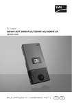
Download SUNNY BOY 2000HF-US / 2500HF-US / 3000HF-US
Transcript
PV Inverter
SUNNY BOY 2000HF-US/2500HF-US/3000HF-US
User Manual
HF_STP_US-BUS095110 | TBUS-20HF | Version 1.0
CA
US
Please contact SMA.
Device fault
Failure that can be removed on-site (see chapter 10.3 )
Power curve or energy
curve of the past 16 feedin hours or past 16 days (switching the display is done by knocking on the lid)
• Sunny Boy might need better ventilation
• Clean the fan (if necessary)
Power reduction due to excessive temperature
PV array event number Input voltage / input current
Grid event number
Output voltage / output current
Sunny Boy event number
Grid relay
Bluetooth connection to other Sunny Boys
• Switching through the line display
• Switching through the power values of the past 16 feedin hours to the daily power values of the past 16 days
• Activating the background illumination
Knocking on the upper lid:
Event text
Total energy fed
in since the Sunny Boy was installed
Daily energy
Actual output
SMA America, LLC
Legal Restrictions
Copyright © 2011 SMA America, LLC. All rights reserved.
No part of this document may be reproduced, stored in a retrieval system, or transmitted, in any form
or by any means, electronic, mechanical, photographic, magnetic or otherwise, without the prior
written permission of SMA America, LLC.
Neither SMA America, LLC nor SMA Solar Technology Canada Inc. makes no representations,
express or implied, with respect to this documentation or any of the equipment and/or software it may
describe, including (with no limitation) any implied warranties of utility, merchantability, or fitness for
any particular purpose. All such warranties are expressly disclaimed. Neither SMA America, LLC nor
its distributors or dealers nor SMA Solar Technology Canada Inc. nor its distributors or dealers shall
be liable for any indirect, incidental, or consequential damages under any circumstances.
(The exclusion of implied warranties may not apply in all cases under some statutes, and thus the
above exclusion may not apply.)
Specifications are subject to change without notice. Every attempt has been made to make this
document complete, accurate and up-to-date. Readers are cautioned, however, that
SMA America, LLC and SMA Solar Technology Canada Inc. reserve the right to make changes
without notice and shall not be responsible for any damages, including indirect, incidental or
consequential damages, caused by reliance on the material presented, including, but not limited to,
omissions, typographical errors, arithmetical errors or listing errors in the content material.
All trademarks are recognized even if these are not marked separately. Missing designations do not
mean that a product or brand is not a registered trademark.
The Bluetooth® word mark and logos are registered trademarks owned by Bluetooth SIG, Inc. and
any use of such marks by SMA America, LLC and SMA Solar Technology Canada Inc. is under
license.
SMA America, LLC
3801 N. Havana Street
Denver, CO 80239 U.S.A.
SMA Solar Technology Canada Inc.
2425 Matheson Blvd
8th Floor
Mississauga, ON L4W 5K5
Canada
User Manual
HF_STP_US-BUS095110
3
Important Safety Instructions
SMA America, LLC
IMPORTANT SAFETY INSTRUCTIONS
SAVE THESE INSTRUCTIONS
This manual contains important instructions for models Sunny Boy 2000HF‑US, 2500HF‑US,
3000HF‑US PV inverter, that must be followed during installation and maintenance of the PV inverter.
The models Sunny Boy 2000HF-US, 2500HF-US, 3000HF-US are designed and tested according to
international safety requirements, but as with all electrical and electronic equipment, certain
precautions must be observed when installing and/or operating the models Sunny Boy 2000HF-US,
2500HF-US, 3000HF-US. To reduce the risk of personal injury and to ensure the safe installation and
operation of the models Sunny Boy 2000HF-US, 2500HF-US, 3000HF-US, you must carefully read
and follow all instructions, cautions and warnings in this user manual.
Warnings in this document
A warning describes a hazard to equipment or personnel. It calls attention to a procedure or practice,
which, if not correctly performed or adhered to, could result in damage to or destruction of part or all
of the SMA equipment and/or other equipment connected to the SMA equipment or personal injury.
DANGER
DANGER indicates a hazardous situation which, if not avoided, will result in death or
serious injury.
WARNING
WARNING indicates a hazardous situation which, if not avoided, could result in death or
serious injury.
CAUTION
CAUTION indicates a hazardous situation which, if not avoided, could result in minor or
moderate injury.
NOTICE
NOTICE is used to address practices not related to personal injury.
4
HF_STP_US-BUS095110
User Manual
SMA America, LLC
Important Safety Instructions
Other Symbols in this document
In addition to the safety and hazard symbols described on the previous pages, the following symbol
is also used in this user manual:
Information
This symbol accompanies notes that call attention to supplementary information that you
must know and use to ensure optimal operation of the system.
Markings on this product
The following symbols are used as product markings with the following meanings.
Warning regarding dangerous voltage
The product works with high voltages. All work on the product must only be performed
as described in it‘s documentation.
Beware of hot surface
The product can become hot during operation. Do not touch the product during
operation.
Observe the operating instructions
Read the product’s documentation before working on it. Follow all safety precautions
and instructions as described in the documentation.
This inverter is evaluated to UL 1741, which includes assessment to all of the
requirements of IEEE1547 and IEEE1547.1, which are an outgrowth and further
development of the IEEE recommended practices and guidelines contained in IEEE Std.
929-2000. IEEE 929-2000 provides recommendations regarding the proper equipment
and functionality necessary to ensure compatible operation when power generation is
connected to the utility grid. The inverter is additionally evaluated to CAN/CSA C22.2
No. 107.1-1.
User Manual
HF_STP_US-BUS095110
5
General Warnings
SMA America, LLC
General Warnings
General Warnings
All electrical installations must be done in accordance with the local codes and National
Electrical Code® ANSI/NFPA 70 or the Canadian Electrical Code® CSA C22.1.
The Sunny Boy contains no user-serviceable parts except for the fan on the bottom of the
enclosure. For all repair and maintenance always return the unit to an authorized SMA
Service Center.
Before installing or using the Sunny Boy, read all of the instructions, cautions, and warnings
on the Sunny Boy in this installation guide.
Before connecting the Sunny Boy to the power distribution grid, contact the local power
distribution grid company. This connection must be made only by qualified personnel.
6
HF_STP_US-BUS095110
User Manual
SMA America, LLC
Table of Contents
Table of Contents
1
1.1
1.2
1.3
1.4
Notes on this Manual. . . . . . . . . . . . . . . . . . . . . . . . . . . . . .
Validity . . . . . . . . . . . . . . . . . . . . . . . . . . . . . . . . . . . . . . . . . . . .
Target Group . . . . . . . . . . . . . . . . . . . . . . . . . . . . . . . . . . . . . . .
Additional Information . . . . . . . . . . . . . . . . . . . . . . . . . . . . . . . .
Nomenclature . . . . . . . . . . . . . . . . . . . . . . . . . . . . . . . . . . . . . . .
9
9
9
9
9
2
2.1
2.2
2.3
Safety . . . . . . . . . . . . . . . . . . . . . . . . . . . . . . . . . . . . . . . . . 10
Appropriate Usage . . . . . . . . . . . . . . . . . . . . . . . . . . . . . . . . . . 10
Safety Instructions . . . . . . . . . . . . . . . . . . . . . . . . . . . . . . . . . . . 11
Identifying the Product . . . . . . . . . . . . . . . . . . . . . . . . . . . . . . . 12
3
3.1
Operating Modes. . . . . . . . . . . . . . . . . . . . . . . . . . . . . . . . 13
LED Displays . . . . . . . . . . . . . . . . . . . . . . . . . . . . . . . . . . . . . . . 14
3.1.1
All LEDs are off . . . . . . . . . . . . . . . . . . . . . . . . . . . . . . . . . . . . . . . . . . . . . . . 14
3.1.2
Green LED is flashing . . . . . . . . . . . . . . . . . . . . . . . . . . . . . . . . . . . . . . . . . . 14
3.1.3
Green LED is continuously lit . . . . . . . . . . . . . . . . . . . . . . . . . . . . . . . . . . . . . 14
3.1.4
Red LED is continuously lit . . . . . . . . . . . . . . . . . . . . . . . . . . . . . . . . . . . . . . . 15
3.1.5
Blue LED is continuously lit . . . . . . . . . . . . . . . . . . . . . . . . . . . . . . . . . . . . . . 15
4
4.1
Information on the Display . . . . . . . . . . . . . . . . . . . . . . . . 16
Display Information Overview . . . . . . . . . . . . . . . . . . . . . . . . . 16
5
5.1
5.2
5.3
Maintenance and Cleaning . . . . . . . . . . . . . . . . . . . . . . . . 19
Cleaning the Fan. . . . . . . . . . . . . . . . . . . . . . . . . . . . . . . . . . . . 19
Cleaning the Display. . . . . . . . . . . . . . . . . . . . . . . . . . . . . . . . . 19
Checking the SMA DC Disconnect . . . . . . . . . . . . . . . . . . . . . . 20
6
FCC Compliance Information . . . . . . . . . . . . . . . . . . . . . . 21
7
Contact . . . . . . . . . . . . . . . . . . . . . . . . . . . . . . . . . . . . . . . . 22
User Manual
HF_STP_US-BUS095110
7
Table of Contents
8
HF_STP_US-BUS095110
SMA America, LLC
User Manual
SMA America, LLC
Notes on this Manual
1 Notes on this Manual
This manual contains instructions for operating the Sunny Boy inverter. Store this manual so that it is
always easily accessible.
1.1 Validity
This manual applies to the following inverters:
• Sunny Boy 2000HF-US (SB 2000HF-US‑30)
• Sunny Boy 2500HF-US (SB 2500HF-US‑30)
• Sunny Boy 3000HF-US (SB 3000HF-US‑30)
1.2 Target Group
This manual has been prepared for use by qualified personnel and those operating the inverter.
Activities to be carried out by qualified personnel have been noted with safety instructions.
• Qualified Personnel
Qualified personnel have received training and have demonstrated skills and knowledge in the
construction and operation of the device. Qualified personnel are trained to deal with the
dangers and hazards involved in installing electric devices.
• Operator
The operator has been adequately trained and instructed by qualified personnel in order to
ensure safe operation of the inverter.
1.3 Additional Information
The installation guide included with the equipment contains information regarding assembly,
installation, commissioning and maintenance of the inverter as well as technical specifications
pertaining to the equipment.
Further information about SMA America Production, LLC equipment is available in the download
section of the website www.SMA-America.com.
The download section includes, among others, the technical description: ”SMA Bluetooth® Wireless
Technology”.
1.4 Nomenclature
In this document SMA America Production, LLC and SMA Solar Technology Canada Inc. are referred
to in the following as SMA.
User Manual
HF_STP_US-BUS095110
9
Safety
SMA America, LLC
2 Safety
2.1 Appropriate Usage
The Sunny Boy is a solar inverter that converts the DC current of the PV array into an AC current and
feeds it into the grid.
Refer to the inverter installation guide for detailed information about the product and its intended use.
The limit values specified in the installation guide of the respective inverter must be strictly adhered to.
The inverter may only be operated with PV arrays (modules and cabling) that have protective
insulation. Do not connect any power sources other than PV modules to the inverter.
Do not use the inverter for purposes other than those described here. Alternative uses, modifications
to the inverter or the installation of components not expressly recommended or sold by the
manufacturer void the warranty claims and operating permission.
Contact the SMA Serviceline if you need clarification regarding proper use of the inverter.
Principle of the string inverter
The string inverter connects solar modules that are connected in series (strings) to the power
distribution grid. Thus, even large PV arrays can be set up using multiple individual strings, each
having its own respective string inverter.
Principle of a grid-connected PV system with a Sunny Boy
Position
A
B
C
D
E
F
10
Description
PV array
Sunny Boy with integrated DC disconnect
Line circuit breaker
Load
Engery meter
Power distribution grid
HF_STP_US-BUS095110
User Manual
SMA America, LLC
Safety
2.2 Safety Instructions
DANGER
High voltages in the inverter. Death resulting from electric shock and burns.
The following work on the inverter may be carried out by qualified personnel only.
• Electrical installation
• Repairs
• Modification
Even if an external supply is not present, the equipment may still be under high voltage. This
high voltage can lead to death or severe injuries.
CAUTION
The enclosure of the Sunny Boy can get hot during operation. Risk of burn injuries.
• Do not touch the enclosure during operation.
• Only touch the lid and display during operation.
NOTICE
Damage to the inverter due to overvoltage.
• Verify that the DC voltage of your installation does not exceed the maximum values
specified on the type rating label.
User Manual
HF_STP_US-BUS095110
11
Safety
SMA America, LLC
2.3 Identifying the Product
You can identify the inverter by the type plate. The type
plate is on the right side of the enclosure.
The type plate specifies among other things the device
type (Type / Model), the serial number (Serial No.) and
device-specific key data of the product.
12
HF_STP_US-BUS095110
User Manual
SMA America, LLC
Operating Modes
3 Operating Modes
The inverter indicates various operating conditions with the help of 3 LEDs on the enclosure lid. The
equipment must be connected to a DC power supply. Furthermore the equipment must be connected
to the grid on the AC side to be able to indicate its operational state via display and integrated LEDs.
There must be adequate solar radiation for the inverter to receive the necessary DC voltage.
LED
A
Description
Green LED
B
LED lit: Inverter in normal operating mode
LED flashing: Inverter waiting for adequate solar radiation
Red LED
C
LED lit: Fault in the inverter. Note the serial number of the inverter and the fault
number and contact your installer. The fault number is indicated on the inverter
display unit.
Blue LED
LED lit: Inverter is connected to a Bluetooth network and can communicate with
other devices having the same NetID.
LED display
In case you do not have any communication devices available, monitor the LEDs of the
inverter and graphic display regularly at various times during the day and under varying
conditions of solar radiation, particularly in the first year after installation. Thus, you can
detect any potential faults in the system in a timely manner.
The following section contains a detailed description of various LED displays and inverter operating
states.
User Manual
HF_STP_US-BUS095110
13
Operating Modes
SMA America, LLC
3.1 LED Displays
3.1.1 All LEDs are off
Overnight shutdown
The DC voltage on the inverter is too low for grid feeding.
If this operating state occurs during the day with proper
solar radiation, have your installer check the DC voltage.
3.1.2 Green LED is flashing
Startup
The DC voltage is adequate for the inverter to be
calibrated. However, the DC voltage is not adequate for
feeding operation of the inverter.
Usually, inverter calibration requires less than 10
seconds. Thereafter, the inverter commences normal
feeding operation.
3.1.3 Green LED is continuously lit
Feeding operation
The inverter is operating normally and is feeding power
to the power distribution grid.
14
HF_STP_US-BUS095110
User Manual
SMA America, LLC
Operating Modes
3.1.4 Red LED is continuously lit
The inverter has detected a malfunction within the device
or in the grid. The inverter has disconnected from the
power distribution grid. The inverter indicates the error
number on the display unit (see section 4.1 ”Display
Information Overview” (page 16)). Note the serial
number of the inverter and the error number and contact
your installer.
Troubleshooting by installer
Contact your installation technician, who will troubleshoot the error or get in touch with the
SMA Serviceline.
3.1.5 Blue LED is continuously lit
The inverter is connected to a Bluetooth network.
User Manual
HF_STP_US-BUS095110
15
Information on the Display
SMA America, LLC
4 Information on the Display
The Sunny Boy provides information on the display unit during operation.
Activate display unit background illumination
Activate the display background illumination by tapping on the cover of the enclosure lid.
The background illumination switches off automatically.
4.1 Display Information Overview
Position
A
Description
Performance chart of the past 16 hours / last 16 days.
B
The inverter displays the feed-in power in the performance diagram. By default, the
inverter displays the feed-in power of the past 16 hours. The inverter refreshes the
display every 5 seconds. When you tap on the cover of the enclosure lid, the display
changes and shows the power fed over the past 16 days.
A malfunction has occurred.
C
D
E
The inverter displays this icon when it detects a malfunction in the equipment or the
power grid. The inverter indicates the error number on its display unit. Note the serial
number of the inverter and the error number and contact your installer.
Current inverter output power.
Total energy produced on this day.
Total energy output of the inverter since commissioning.
16
HF_STP_US-BUS095110
User Manual
SMA America, LLC
Information on the Display
Position
A
B
Description
Current DC voltage at the inverter.
Quality of the link to other PV system Bluetooth devices.
C
You can see whether the inverter has a radio link to a device of its PV system on the link
quality icon. The number of rings indicates the quality of the Bluetooth connection
between the devices. The more rings displayed, the better the link quality.
Status display of power feed
Switch closed: The Sunny Boy feeds power to the power distribution grid and supplies
power to loads connected to it directly.
D
User Manual
Switch open: The Sunny Boy does not feed power into the power distribution grid and
does not supply power to any loads connected to it directly.
Current AC main voltage
HF_STP_US-BUS095110
17
Information on the Display
SMA America, LLC
Position
A
Description
PV array event number
B
Shows events that have occurred on the PV array.
Warning icon for power reduction.
C
The temperature in the inverter is too high. The inverter reduces power output in order
to cool down. If the inverter fan is dirty, clean it (see section 5.1 ”Cleaning the Fan”
(page 19)). If the inverter displays the icon even after the fan has been cleaned, ensure
proper ventilation.
Inverter event number.
D
It displays events that have occurred on the inverter.
Grid event number.
E
This displays events that have taken place on the power distribution grid.
Event display line of text.
The text field displays additional information if any events have occurred on the PV
array or on the power distribution grid. Tapping on the lid leads you to further
information on the event.
Display messages
The inverter installation manual provides detailed information regarding event numbers,
various error and malfunction messages.
Measurement accuracy
The inverter does not have a calibrated meter. The values on the display unit may differ
from the actual values. You may not use the values as the basis for any billing purposes.
18
HF_STP_US-BUS095110
User Manual
SMA America, LLC
Maintenance and Cleaning
5 Maintenance and Cleaning
Check for proper inverter operation at regular intervals. Dirt, such as dust, can cause heat
accumulation, which can lead to yield losses. Check the inverter and cables for any signs of external
damage. Have repairs carried out if necessary.
5.1 Cleaning the Fan
WARNING
Only qualified personnel may dismantle the inverter fan.
The procedure for dismantling the fan for cleaning is described in the inverter installation
guide.
If the fan guards are dirty with loose dust, then you can clean them with a vacuum cleaner. Hold the
pipe of the vacuum cleaner below the fan of the inverter (see Figure). If you are unable to clean the
fan properly, contact your installer who will dismantle the fan in order to clean it.
5.2 Cleaning the Display
If the status LED's or the display unit are dirty and cannot be read clearly, clean them using a moist
cloth.
Cleaning the status LED's and the display unit
Do not use any solvents, abrasives or corrosive substances for cleaning.
User Manual
HF_STP_US-BUS095110
19
Maintenance and Cleaning
SMA America, LLC
5.3 Checking the SMA DC Disconnect
When used appropriatly the SMA DC Disconnect does not need maintenance.
It is recommended, though not compulsory to:
• Check the SMA DC Disconnect regularly.
• Operate the SMA DC Disconnect once a year 10 times.
Operating the switch will clean the contacts of the SMA DC Disconnect.
20
HF_STP_US-BUS095110
User Manual
SMA America, LLC
FCC Compliance Information
6 FCC Compliance Information
SMA PV inverter, model Sunny Boy 2000HF-US, Sunny Boy 2500HF-US, Sunny
Boy 3000HF-US
This device complies with Part 15 of the FCC Rules. Operation is subject to the following conditions:
(1) This device may not cause harmful interference, and
(2) this device must accept any interference received, including interference that may cause undesired
operation.
NOTE: This equipment has been tested and found to comply with the limits for a Class B digital
device, pursuant to Part 15 of the FCC Rules. These limits are designed to provide reasonable
protection against harmful interference in a residential installation. This equipment generates, uses,
and can radiate radio frequency energy and if not installed and used in accordance with the
instructions, may cause harmful interference to radio communications. However, there is no guarantee
that interference will not occur in a particular installation. If this equipment does cause harmful
interference to radio or television reception, which can be determined by turning the equipment off
and on, the user is encouraged to try to correct the interference by one or more of the following
measures:
• Reorient or relocate the receiving antenna.
• Increase the separation between the equipment and the receiver.
• Connect the equipment into an outlet on a circuit different from that to which the receiver is
connected.
• Consult the dealer or an experienced radio/TV technician for help.
• The user is cautioned that changes or modifications not expressly approved by
SMA America, LLC could void the user’s authority to operate this equipment.
Contact SMA America for more information.
RF-exposure Statement
The SMA Sunny Boy 2000HF-US, Sunny Boy 2500HF-US, Sunny Boy 3000HF-US contains a
modular transmitter. Thus it must have a separation of at least 8 in. (20 cm) between the antenna and
the body of the user or nearby persons, excluding hands, wrists, feet, and ankles.
User Manual
HF_STP_US-BUS095110
21
Contact
SMA America, LLC
7 Contact
If you have technical problems with our products, please contact our Serviceline. We require the
following information in order to provide you with the necessary assistance:
• Inverter type
• Serial number of the Sunny Boy
• Type and number of modules connected
• Event number or display message of the Sunny Boy
• Type of communication, if applicable
• Type of fault signaling contact connected, if applicable
SMA Solar Technology America, LLC
6020 West Oaks Blvd, Ste 300
Rocklin, CA 95765
Tel. +1 916 625 0870
Tel. +1 877-MY SMA TECH
Tel. +1 877 697 6283 (Toll free, available for USA, Canada and Puerto Rico)
Fax +1 916 625 0871
[email protected]
www.SMA-America.com
SMA Solar Technology Canada Inc.
2425 Matheson Blvd, 8th Floor
Mississauga, ON L4W 5K5, Canada
Tel. +1 877 506 1756 (Toll free, available for Canada)
[email protected]
www.SMA-Canada.ca
22
HF_STP_US-BUS095110
User Manual
4.""NFSJDB--$
XXX4.""NFSJDBDPN
For product and purchase inquiries contact:
www.ecodirect.com


