1
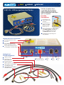
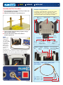
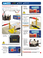
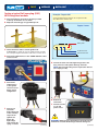
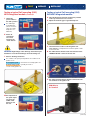
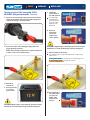
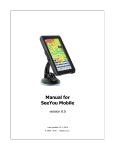
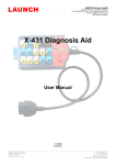
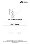
Off-Car
Ignition Coil Tester
Instruction Manual
TEST
REPAIR
EQP-112 Off-Car Ignition Coil Tester
REPLACE
2
The EQP-112 Ignition Tester
is a portable tool for testing a
variety of ignition coils off the
vehicle to determine if the output
spark is acceptable.
Function
Descriptions:
Can output two sets
of drive signals at the
same time;
Has anti-interference
ability, good stability,
high load capacity;
Small, easy to use;
Output signal divided into “direct signal”
and “within module” signal allows
ignition coil with integrated module
and without module to be tested;
Discharging electrode spark gaps are
easily adjustable.
Ignition Coil Tester Control Panel
Discharging Electrode Location.
Metal Case.
Direct Output Signal (to test
ignition coils without modules).
Integrated Module Output Signal
(to test ignition coils with module).
Packing list of
included components:
Ignition Coil Tester.
High‑Voltage Leads
(Red x 1, Black x 1).
Discharge Electrodes
(Metal x 1, Plastic x 1).
2-Wire Cable for testing ignition
coils WITHOUT module.
3-Wire Cable for testing ignition
coils WITH module.
Start / Stop Button for
starting and ending test.
Power
Light.
Power
Switch.
Power
Fuse.
TEST
REPAIR
Assembly and Test Procedure:
A. Place the discharge electrodes in the holes provided at the
top of the tester case as shown.
B. Adjust the electrode gap to approximately 1cm.
REPLACE
3
Example : VW Ignition Coil
For example, to test this VW ignition coil and module assembly
(032905106B) which has two sets of high‑voltage outputs,
one primary input connector and an ignition module. The 3‑Wire
harness cable should be used to test this type of assembly.
Left
high‑voltage
output.
Ignition module.
Right
high‑voltage
output.
C. Select the cable required according to ignition coil type
(with or without module).
D. Connect 3‑Wire harness cable to the combined
module & ignition coil.
NOTE:
Primary
Connector
Terminals
Ignition coil pin
configurations
vary on different
coils. Please CHECK
for correct pin
configuration on
ignition coil to
be tested before
connecting the
harness.
4. “G”
terminal.
3. Left high-
voltage connect
IB signal terminal.
4. Black 3. Yellow
Wire.
This typical waste
spark ignition coil pack requires two outputs (one ignition coil) to be
tested at a time. The other two outputs must be tested separately.
Wire for
left side.
2. “+”
terminal.
1. Right highvoltage connect
IB signal.
2. Red Wire – 1. To test the right
power supply.
side, move the Yellow
wire to this pin.
Test Cable – 3‑Wire to be used for coils
with module
“+” Terminal : Red
“IB” Terminal : Yellow
“G” Terminal : Black
[continued]
TEST
REPAIR
Assembly and Test Procedure (continued) :
E. Connect high‑voltage leads.
NOTE : Testing One Coil (two high‑voltage outlets as shown)
REPLACE
4
H. Ensure all
connections
are correct
and press the
“Start” button.
WARNING: High‑Voltage at the discharge electrodes may be
harmful. Do not touch the discharge electrodes during test.
I. Observe discharge
electrodes.
The condition of
the spark generally
indicates the
condition of the
ignition coil. i.e. :
A strong blue spark
is an indication of a
healthy ignition coil.
A weak orange spark
is generally the result
of a weak or faulty
ignition coil.
J. On completion of
the spark output
test press the
START / STOP
button to end
the test.
F. Connect test unit
to a 12 Volt
power source.
K. Remove and
WARNING: High‑voltage at the discharge electrodes may be
harmful. Do not touch the discharge electrodes during test.
reconnect the
high-voltage
leads to the
other suitable
ignition coil
outlets to
complete the
ignition coil test.
G. Switch the
power switch to
the “ON” position.
L. The 3 pin wire harness will also need to be altered at
the ignition coil to suit the other half of the coil pack
(other two high-voltage outlets) to be tested.
The “PWR” light
should illuminate.
(Check connections
and power supply
if light does not
illuminate).
M. Repeat steps from G to J to monitor the output spark
to determine if the ignition coil is acceptable. [continued]
TEST
REPAIR
REPLACE
Testing a typical Coil over plug (COP)
WITH integrated module:
5
Example : Toyota Coil
Toyota Coil (90919-02230), this item has an ignition module.
The 3‑Wire harness must be used.
A. Place the discharge electrodes in the holes provided
at the top of the tester case as shown.
B. Adjust the electrode gap to approximately 1cm.
Toyota / Lexus
Battery Volts
C. Select the harness cable to suit the ignition coil
Feedback to ECU
to be tested. For example the Toyota Coil (90919-02230) [at right]
has an integrated ignition module. The 3‑Wire harness must be used.
Pulsed Coil Control
D. Connect the 3‑Wire harness to the “SIGNAL OUTPUT” socket
on the test unit.
G. Connect the other end of the high‑voltage lead to the
brass connector of the plastic discharge electrode.
NOTE: Only one high‑voltage lead is required for this test
(one output per coil).
E. Connect the
3‑Wire harness
to the ignition
coil to be tested.
Ensure correct
configuration.
H. Recheck all
connections.
I. Connect test unit
to a 12 Volt
power source.
F. Connect one
end of the
high‑voltage lead
to the secondary
output of the
ignition coil.
Ensure the
high‑voltage
lead contacts the
spring or contact.
WARNING: High‑voltage at the discharge electrodes may be
harmful. Do not touch the discharge electrodes during test.
[continued]
[continued]
TEST
REPAIR
Testing a typical Coil over plug (COP)
WITH integrated module (continued) :
REPLACE
6
Testing a typical Coil over plug (COP)
WITHOUT integrated module:
A. Place the discharge electrodes in the holes provided
J. Switch the
at the top of the tester case as shown.
power switch to
the “ON” position.
B. Adjust the electrode gap to approximately 1cm.
The “PWR” light
should illuminate.
(Check connections
and power supply
if light does not
illuminate).
K. Ensure all
connections
are correct
and press the
“Start” button.
C. Select the harness cable to suit the ignition coil
WARNING: High‑Voltage at the discharge electrodes may be
harmful. Do not touch the discharge electrodes during test.
to be tested. For example IGC-163 Ford Falcon ignition coil has
no internal module.
D. The 2‑Wire harness must be used and connected to the
“MODULE OUTPUT” socket on the test unit.
L. Observe discharge electrodes.
The condition of the spark generally indicates the condition of the
ignition coil. i.e. :
A strong blue spark
A weak orange spark is generally the result of
a weak or faulty ignition coil.
is an indication of a healthy ignition coil.
E. The other end of the harness must be connected to the
two terminals of the ignition coil.
RED Wire to
B+ Terminal
M.On completion of
the spark output
test press the
START / STOP
button to end
the test.
[continued]
TEST
REPAIR
Testing a typical Coil over plug (COP)
WITHOUT integrated module (continued):
REPLACE
7
J. Switch the
power switch to
the “ON” position.
F. Select one end of the high‑voltage lead to the secondary
The “PWR” light
should illuminate.
(Check connections
and power supply
if light does not
illuminate).
output of the ignition coil. Ensure the high‑voltage lead
contacts the spring or internal contact.
K. Ensure all
connections
are correct
and press the
“Start” button.
G. Connect the other end of the high‑voltage lead to the
plastic discharge electrode.
NOTE: Only one high‑voltage lead is required for this test
as there is only one secondary output.
WARNING: High‑Voltage at the discharge electrodes may be
harmful. Do not touch the discharge electrodes during test.
L. Observe discharge electrodes.
The condition of the spark generally indicates the condition of the
ignition coil. i.e. :
A strong blue spark
A weak orange spark is generally the result of
a weak or faulty ignition coil.
H. Recheck all
connections.
I. Connect test unit
to a 12 Volt
power source.
M.On completion of
the spark output
test press the
START / STOP
button to end
the test.
WARNING: High‑voltage at the discharge electrodes may be
harmful. Do not touch the discharge electrodes during test.
is an indication of a healthy ignition coil.
Specialty Tools & Equipment
you can count on !
REPAIR
REPLACE
Quality Products
12 Month Warranty
Technical Support
Available from leading automotive specialists and retailers.
www.plusquip.com.au
PLUSQUIP 8049 05/13
TEST