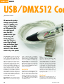
1
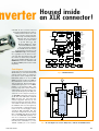
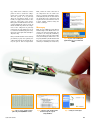
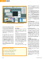
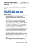
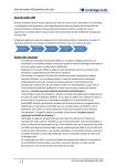
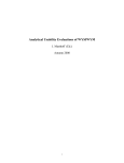
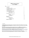
HANDS-ON DMX512
USB/DMX512 Con
Jean-Marc Lienher
All amateur disc jockeys
and light jockeys dream
about it: a DMX512 converter not bigger than
an XLR connector! But
at a retail price of
more than 500
pounds for this type
of accessory, the
dream may never
come true. Here is a
project that will make
some on the dance floors
very happy... the DMX
converter of their dreams
and for only a few pounds.
The USB/DMX512 converter described
in this article connects to any computer equipped with a USB connector
and a Windows® 98 OS or later. The
USB (bus) supplies the current necessary to power the circuit we’ve
designed. The proposed setup transmits the 512 DMX channels at a
rhythm of approximately 42 frames per
second using a computer equipped
with a USB 2.0 interface. The maximum speed defined by the standard is
44 frames per second. Note that this
transmission rate may be a little less
with a USB 1.0 connection. The printed
circuit board we designed for the converter measures 14 mm by 26 mm and
employs SMD components.
Important note: our circuit, like many
DMX converters sold in retail shops
70
(some of which come at exorbitant
prices), does not include full electrical
isolation. This is not terribly important
when using a DMX device that’s operating properly, but could prove fatal
for your computer if, unfortunately, a
mains phase conductor of a defective
projector or floodlight should come into
contact with the DMX512 line. Forewarned is forearmed!
A PIC16C745
The PIC16C745, of which the block diagram can be found in Figure 1, is a
low-cost microcontroller. However, it
was one of the first to have a USB
interface. In reality, it is a type 1.1 lowspeed USB interface. The transmission
rate of the USB bus in low speed mode
is 1.5 Mbits/second.
The
DMX512 bus
speed is a ‘measly’ 250 kbits/s. The
USB is six times faster, so where is
the problem? Well, for one thing the
USB standard defines two data transfer modes for low speed, Control
transfer and Interrupt transfer. The
control mode uses all of the bus bandwidth and is, according to the standard, reserved for USB receiver configurations. The Interrupt mode is
intended for data transfer but we
should note that it is limited to 800
bytes per second!
Out of spec!
With the above in mind we’re more or
less forced to use the 16C745 in a configuration that’s not found in the USB
elektor electronics - 9/2006
standard. To do so, we have selected
the Control transfer mode in order to
exchange data between the computer and the microcontroller.
Obviously, considering that the
USB bus was not designed
for that use, we had to write
a special driver for this
Microsoft Windows® application. The firmware source
code for the microcontroller
is available from our website
at www.elektor-electronics.co.uk
(file # 060129-11.zip). Unfortunately,
the copyrights for the driver source
code rest with the author, hence this
file cannot be made freely available.
The pre-programmed PIC (order code
060129-41) is however available from
the Elektor SHOP (on the web or in this
magazine)
13
Program
Memory
9/2006 - elektor electronics
RAM Addr (1)
PORTB
9
Addr MUX
Instruction reg
7
Direct Addr
8
RB0/INT
Indirect
Addr
RB<7:1>
FSR reg
STATUS reg
8
PORTC
3
Powe r-up
Timer
OSC1/
CLKIN
OSC2/
CLKOUT
Instruction
Decode &
Control
Oscillator
Start-up Timer
Timing
Generation
x4 PLL
Watchdog
Timer
Brown-out
Reset
RC0/T1OSO/T1CKI
RC1/T1OSI/CCP2
RC2/CCP1
RC6/TX/CK
RC7/RX/DT
MUX
ALU
Powe r-on
Reset
8
PORTD
W reg
RD3:0/PSP3:0 (2)
RD4/PSP4(2)
RD5/PSP5(2)
RD6/PSP6(2)
RD7/PSP7(2)
Parallel Slave Port (2)
VDD, V SS
MCLR
Timer0
Timer1
CCP2
CCP1
PORTE
Timer2
RE0/AN5/RD (2)
RE1/AN6/WR (2)
RE2/AN7/CS (2)
8-bit A/D
Dual Port
RAM
64 x 8
USART
USB
VUSB
DD+
XCVR
Note 1: Higher order bits are from the STATUS register.
2: Not available on PIC16C745.
Circuit diagram
A quick look at the diagram in Figure 2 allows you to better understand
why the circuit can be so compact: it
has only two active components! The
PIC16C745 (IC2) in its 28-pin SMD
SOIC version is clocked at 6 MHz by
X1, a miniature resonator with integrated capacitors. The internal microcontroller frequency is set to 24 MHz,
thanks to its integrated PLL, thus
lowering any risk of stray radiation
which might occur when using a resonator at this frequency. The PIC generates the 3.3 V voltage necessary on
1.5 kW SMD resistor R1 connected to
the D– line of the USB cable. A 220-nF
SMD capacitor, C2, smoothes this
voltage supplied directly by the
microcontroller pin. Pins D+ and D–
of the PIC are directly connected to
the USB bus. The second capacitor,
C1, is included to suppress fluctuations in the 5-volt supply voltage
caused by PIC switching. The last
electronic component in the circuit,
IC1, is an RS485 bus driver for which
we use the SMD SO8 package version. It is connected to the USART
((Universal Synchronous & Asynchronous Receiver Transmitter ) of the
16C745 enabling it to be used bi-
14
RA0/AN0
RA1/AN1
RA2/AN2
RA3/AN3/VREF
RA4/T0CKI
RA5/AN4
RAM
File
Registers
256 x 8
8 Level Stack
(13 bit)
8K x 14
Program
Bus
PORTA
8
Data Bus
Program Counter
EPROM
060012 - 12
Figure 1. PIC16C745 architecture.
+5V
IC1
C1
8
150n
1
20
1
1
2
3
4
RC7
MCLR
+5V
RC6
D–
15
D+
16
GND
D–
IC2
D+
RB7
R1
RB6
1k5
nverter
Housed inside
an XLR connector!
RB5
RB4
14
13
12
C2
11
220n
VUSB
RB3
RC2
RB2
RC1
RB1
RC0
RB0
PIC16C745SO
RA5
RA4
9
X1
RA3
OSC1
RA2
RA1
10
RA0
OSC2
8
18
2
17
3
28
4
R
6
DO
7
DO
25
7
D
5
27
26
6
GND_DMX
5
DS75176BM
24
23
22
21
7
6
5
4
3
2
19
060012 - 11
Figure 2. The circuit diagram of our converter is limited, in fact, to a PIC micro and an RS485 bus driver.
71
HANDS-ON DMX512
directionally, in case you would like
to modify the firmware of the PIC to
use it as a DMX512 input. The noninverting buffer output of the RS485
driver is connected to pin 3 of the
XLR connector and the inverter output is connected to pin 2, since pin 1
is connected to ground. As far as the
USB cable and connector are concerned, this is a moulded cable sold
in retail stores or the one with your
old mouse (USB, of course!). It has
four wires plus shielding: a pair of
untwisted, fairly thick wires for the
5 V power supply voltage and two
thinner wires, twisted as pair, for
data transmission. XLR connectors
are supplied by many manufacturers.
Here, a, Cannon type 10HC089 is
used. It is important to use this XLR
connector because a standard Neutrik connector does not have enough
space to hold the circuit.
Programming the PIC
060012-1
7 2
3
1
IC1
5
4
C1
Figure 3. Not for the faint-hearted...
X1
060012-1
060012-1
Figure 4. The PIC occupies almost all space at one of the board sides.
This double-sided board is through-plated.
The PIC 16C745 micro has to be programmed before soldering it onto the
board. If you’re a home programmer,
make sure you have a suitable DIL-toSOIC adaptor with your programmer.
Alternatively, as we did in our tests
(see the photo in Figure 3), you can
make one yourself using a DIL carrier, a
piece of flatcable and a test clip for
SOIC circuits. The hex (object code) file
to burn into the PIC is called
firmware\usb2dmx.hex. It is contained in archive file 060012-11.zip
which may be downloaded free of
charge from our website. The PIC may
also be purchased ready-programmed
from the Elektor SHOP.
Heat up your soldering irons!
COMPONENTS
LIST
Resistors
R1 = 1kΩ5 0.25W 5% (0805)
Capacitors
C1 = 150nF ceramic (0603)
C2 = 220nF ceramic (0603)
Semiconductors
IC1= DS75176BM (National
72
Semiconductor)
IC2 = PIC16C745-I/SO, programmed,
order code 060012-41
Miscellaneous
X1 = 6MHz resonator, Murata
CSTCR6M00G53-R0
XLR connector, Cannon type 10HC089
(e.g. www.distrelec.com, #
112242)USB A-A cable, 1.8m,
standard
PCB, ref. 060012-1 from The PCBshop
Project software, free download #
060012-11.zip from www.elektorelectronics.co.uk
Populating the board requires some
skills handling SMD parts but should
not cause dramatic problems. Fortunately, the components used for this
project are not as difficult to solder as,
for example, an ARM processor in a
BGA package with 278 balls, sized 14
mm x 14 mm!
The printed circuit board of which the
top and bottom side artwork is shown
in Figure 4 is without doubt, one of the
smallest we have ever published in
Elektor Electronics.
You need to use a soldering iron with a
fine tip and thin gauge solder. Start by
soldering the PIC micro, IC2, into place
(be careful to observe the correct polar-
elektor electronics - 9/2006
ity), which then constitutes a base
plane in order to solder the components on the other side of the circuit.
The best option, so as to perfectly
align the integrated circuit on the
board, is to apply a bit of solder to two
pads for corner pins of the device.
Next, place the PIC and reheat the two
solder terminals in order to create an
initial attachment point for the component. If the component is perfectly
positioned, the only thing left to do is
to solder the remaining 26 pins. If not,
reheat the corner pins and carefully realign the chip.
Next, solder R1 and C2 on this side by
pre-tinning a pad, then placing the
component with tweezers while keeping the pad at fusion temperature.
Figure 6. The ‘test_cpp.exe’ program is used for
quick testing of our USB/DMX512 converter.
9/2006 - elektor electronics
Next, solder the other connection of
the component. Use the same technique to solder the remaining components (IC1, C1, X1) on the other side of
the board. X1 is the component that
requires the most attention because it
is more usually soldered using the
‘reflow’ technique.
Microsurgery
Next, we cut a USB type ‘A-A’ cable in
half and strip it. The black wire is soldered to the 0 V pad (terminal 4), the
red wire to the +5V pad (terminal 1),
the green wire to the D+ pad (terminal 3) and finally the white wire to the
D– pad (terminal 2). You’ll find that this
bit of the construction requires some
dexterity in handling the solder iron,
Figure 7. The purpose of the oGenInt.sys driver
function is to shape the ‘requests’
sent by the USB bus.
Figure 5. If you are used to installing USB
peripherals, this type of screen should look
familiar.
Figure 8. Settings screen in FreeStyler.
73
HANDS-ON DMX512
ure 6, is used to quickly test the operation of the USB/DMX512 converter. Its
source code demonstrates the way to
use the unique function exported from
DLL DasHard.dll.
The really important bits happen in
the test_cppDlg.cpp file. More specifically, the CTest_cppDlg::OnVScroll
function copies the value of the cursors in the OutDmx output buffer.
And the CTest_cppDlg::OnTimer
function, called on at regular intervals, loads the DLL and obtains a
pointer on the OksidCommand function during its first call. During the following calls, it simply passes the output buffer to the OksidCommand
function.
Figure 9. The number of functions available in FreeStyler makes it quasi-professional.
since there are no holes in the printed
circuit. The cable shielding is soldered
to the connector strip. The next step is
to solder the circuit to the XLR connector, from which the rubber cable guide
has been cut. Terminal 5 should be soldered to pin 1 of the XLR connector,
terminal 6 to pin 3, and finally terminal 7 to pin 2.
Before applying a little glue to keep
the USB cable in place and to close
the XLR connector again, test the setup by connecting it to your computer.
When the new USB device is inserted
for the first time, you will be asked to
install the drivers provided in the .zip
file 060012-11.zip (Figure 5). Once
the drivers are installed, connect the
XLR plug to your DMX512 equipment
and
launch
the
program
cpp_test\bin\test_cpp.exe which is
found in the same archive file. There
you have it!
Software environment
PIC firmware
The assembly code of the PIC is
derived from version 1.25 of the
firmware provided on Microchip’s
website, the manufacturer of the
PIC16C745.
We used version 1.25 because version
2.00 did not seem to function with the
erasable PICs we had available. The
file usb_main.asm contains an endless
loop reading batches of data sent by
the computer. These data are utilised
in the dmx512.asm file that synchronises the USB reception with the transmission on the serial DMX512 bus.
Also in this file we find the code that
serves to generate the pause required
at the end of each DMX field.
The test_cpp.exe program
This program, shown in action in Fig-
Internet links :
The DLL DasHard.dll
This one links it all to the driver and,
provided a converter is connected to
the computer, opens a data stream
with it. This stream is fed by a specific
thread that loops as long as the DLL is
used. Refer to the source code for more
details.
The oGeniInt.sys driver
The driver (see the screenshot in Figure 7), of which the source code is
regrettably not available, is in charge
of shaping Control-type requests travelling on the USB bus. The
OGENINT.INF file makes the driver
installation possible. It creates the
association between the driver with
our USB module, thanks to the
Vendor ID and Product ID identifiers
that are specific to our application.
FreeStyler,
free DMX512 driver software.
FreeStyler is software written in Visual
Basic that makes it possible to drive
DMX512 equipment by indifferently
using an impressive variety of converters for the parallel, USB, or Ethernet
port. As shown in the screenshot in
Figure 8, the latest version also functions with our circuit using the reference ‘Oksidizer USB2DMX’. FreeStyler
is available as a free download from
the website run by the author of the
program. It comes with a complete
user manual.
Author’s website: http://www.oksidizer.com
http://membres.lycos.fr/epatix/dmx_512.htm
http://users.pandora.be/freestylerdmx/
http://www.beyondlogic.org/usbnutshell/
http://ogloton.free.fr/dmx_512/index.html
The screen copy in Figure 9 shows
that FreeStyler offers a range of functions that may disconcert a beginner
but will be welcomed as very useful by
(DMX512-)enlightened amateurs and
professionals.
(060012-1)
74
elektor electronics - 9/2006