1
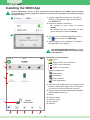
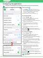
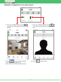
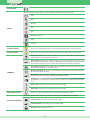
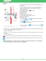
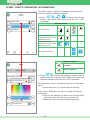
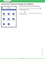
EN USER MANUAL User Manual App VEDO 2.1.0 FOR DEVICES: Index Installing the VEDO App ................................................................................................................. 3 Configuring the application ........................................................................................................... 4 Device connection...................................................................................................................4 For local connection................................................................................................................4 For remote connection............................................................................................................4 Using the VEDO App ....................................................................................................................... 5 RECEIVING AN ALARM NOTIFICATION .........................................................................................................5 In the event of a zone alarm with dedicated camera..............................................................5 ANSWERING A CALL.......................................................................................................................................6 VIEWING A CAMERA OR CALLING AN APP ..................................................................................................7 VIEWING THE STATUS OF THE SYSTEM AREAS ........................................................................................8 TASTI FUNZIONE ............................................................................................................................................8 VIEWING AND CONTROLLING INTRUSION AREAS .....................................................................................10 VIEWING THE STATUS OF THE INTRUSION ZONES ...................................................................................11 VIEWING THE STATUS OF THE ZONES ........................................................................................................11 Settings ................................................................................................................................... 12 DEVICE ID ........................................................................................................................................................12 DEVICE PASSWORD .......................................................................................................................................12 INACTIVITY TIMEOUT .....................................................................................................................................12 STREAMING BITRATE ....................................................................................................................................12 DISCONNECTION NOTIFICATION .................................................................................................................12 RINGTONE .......................................................................................................................................................12 IP ADDRESS ....................................................................................................................................................12 DOOR ...............................................................................................................................................................12 Configuring Bridge Art. 20003101 and 20090334 ......................................................................... 13 Using home automation Bridge Art. 20003101 ............................................................................. 13 REMOTE PARAMETERS .................................................................................................................................13 H.A. BRIDGE SETTINGS .................................................................................................................................13 INFO .................................................................................................................................................................13 For local connection:...............................................................................................................13 For remote connection:...........................................................................................................13 CLIMA ...............................................................................................................................................................14 OTHER / LIGHTS / IRRIGATION / AUTOMATIONS.........................................................................................15 SHUTTER .........................................................................................................................................................16 CONSUMPTION ...............................................................................................................................................17 SCENARIOS.....................................................................................................................................................17 Using home automation Bridge Art. 20090334 ............................................................................. 18 This document may not be reproduced, even in part, without the express written consent of Comelit Group spa. The brands and commercial names appearing in this publication remain the property of their respective owners. 2 Installing the VEDO App System requirements: iOS 6.0 or later, anti-intrusion control panels in the VEDO range by Comelit from version 2.2.0, Ethernet expansion module from version 2.2.0 and internet connection (for using the App remotely). 1. Log in to App Store, search for “Comelit” or “VEDO” in the search engine and install the free VEDO APP. 2 2. Activate a network connection 2a. connect to your router to connect locally; 2b. activate the data connection for your mobile device to connect remotely. 4 3. From the list of installed applications, press the icon to open the VEDO app. 4. When it opens, press "Settings" to configure the application (see page 4). THE USER PASSWORD (DEFAULT = 111111) WILL BE REQUESTED EVERY TIME ACCESS IS ATTEMPTED. Description of the interface 1. Status icon: 1 VEDO: device not connected VEDO: user connected 2 VEDO: no connection default configuration: Reset alarms Stop alarms 3 Total activation Total deactivation 3. Cameras and mobile devices connected to the system (mobile devices are only visible when connected to the local Ethernet network) 4. System status (activated/deactivated/partially activated/alarm memory...) 5. Home 6. Intrusion areas 7. Intrusion zones 8. Zone status 9. Settings 4 5 6 7 8 9 3 Configuring the application For the data to be entered during configuration and setup, contact your regular installer. Device connection 1. In "Settings" press "Device ID" and enter the App identification number provided by your installer (between 1 and 8).Press to return to settings. 2. Enter the device password (default = 0). For local connection 1. Press "Settings" 2. Scroll down the screen until you reach the "LOCAL PARAMETERS" section. 3. Enter the IP address for the control panel card (default = 192.168.1.230). 4. Leave the setting "Port" as it is (default = 10012) unless advised otherwise by your installer. 5. Scroll all the way through the screen and press "Save". Once configuration is complete the status icon will turn green to show that the application is configured correctly. For remote connection 1. Press "Settings" 2. Scroll down the screen until you reach the "REMOTE PARAMETERS" section. 3. Press "Remote control parameters" to access the relevant configurations. 4. Enter the "IP address/Hostname" (registered for the control panel or serial bridge) provided by your installer. 5. Do not change the remaining connection parameters (unless advised otherwise by your installer). 6. Activate the "Secure Web" option to use a secure connection when connecting to the control panel remotely. 7. Scroll all the way through the screen and press "Save". Once configuration is complete the status icon will turn green to show that the application is configured correctly. If the VEDO App does not register, contact your installer. 4 Using the VEDO App RECEIVING AN ALARM NOTIFICATION When an alarm notification is received, you will hear the selected ringtone and an alert window will open. Only if the application is running in the background, an alert window will appear on the display. } Press the notification to access the application. In the event of a zone alarm with dedicated camera When an alarm notification is received, you will hear the selected ringtone and an alert window will open. Only if the application is running in the background, an alert window will appear on the display. } Press the notification to access the application. 1. Press "Show" to view the 4 frames captured by the camera installed in the zone in which the alarm has been triggered. 2. Wait for the images to download. 3. Scroll through the images by moving your finger to the right or to the left. } Press to enable the connected camera. } Press to cycle through several cameras (where applicable). } Press to switch off the camera. * To receive notifications: • enable receiving notifications in the Settings area of your mobile phone, via "Settings" / Notification Center. • enable the individual Vedo app for receiving notifications and set the desired receiving method. Depending on the notification type, various ringtones will sound: in the event of an alarm or sabotage a "siren" type ringtone will be played, while in other cases 5 ANSWERING A CALL When a call is received from another mobile device with the VEDO App, you will hear the selected ringtone. Only if the application is running in the background, an alert window will appear on the display. } Press the alert to accept the call. } Press to enable the audio. } Press to stop the call. 6 VIEWING A CAMERA OR CALLING AN APP 1. From the "HOME" screen press to acquire the video signal for the relevant camera. 1. From the "HOME" screen press to call a user connected to the system via the app. } Press } Press to cycle through several cameras (where applicable). } Press "Close" to switch off the camera. 7 to stop the call VIEWING THE STATUS OF THE SYSTEM AREAS } From the "HOME" screen press the system status to view the status of the areas. AREA STATUSES Alarm Deactivated Total Alarm Activation Partial Activation (P1 / P2 / P1+P2 ) In Alarm / Alarm Memory } Press "Close" to return to the HOME screen. FUNCTION KEYS Press the function key to activate the action associated with it. Up to 4 function keys can be set to carry out the functions described on the next page. If the function key is configured as “Activate Output”, “Toggle Output” or “Deactivate Output”: Press and hold the function key to view the status of the corresponding output. 8 NO FUNCTION Allows you to assign the generation of one of the alarms listed below to the function key: 24 H Flood Burglary ALARM Gas Fire Medical Emergency Panic Robbery ACTIVATE OUTPUT Allows you to assign the activation of one of the programmed outputs to the function key. TOGGLE OUTPUT Allows you to assign the function key to toggle (change the status of) the selected output. Authorise installer: authorises the installer code. Has the same effect as authorising the installer code from the keypad via the user menu. Reset alarms: resets the control panel conditions and alarms in progress, but not the events that triggered the alarms which, if still active, will trigger a new alarm cycle. After this command, the control panel assumes the same status as it would assume following an activation. Reset telephone calls: blocks all phone calls, on landline and GSM network. Also blocks any messages envisaged but not sent (SMS, email). COMMAND Request assistance: allows you to send a request for assistance to one or more recipients, by means of a phone call. (NIY) Stop alarms: stops the alarms in progress, regardless of whether the events that triggered them are still active. Does not stop alarms with the attribute Silent. Overtime: this command allows you to delay an automatic activation by n hours, where n is programmable, for the purpose of allowing work to continue beyond the envisaged activation time. Event 1 key: activates the event programmed by the installer. Event 2 key: activates the event programmed by the installer. DEACTIVATE OUTPUT Allows you to assign the function key to deactivate the programmed output. Allows you to assign to the function key one of the possible activation/deactivation programmes: ACTIVATION SCENARIO Total Activation of the alarm across the entire system. Total Deactivation of the alarm across the entire system. Scenario n (with n between 1 and 16). 9 VIEWING AND CONTROLLING INTRUSION AREAS The Intrusion areas section can be used to activate, deactivate and view the status of the alarm system areas. This chapter illustrates how the “alarm” section works for VEDO series control panels. 1 } Press to access the screen "Intrusion areas". (1) Alarm system status icon 1A KITCHEN 2 System Deactivated System Activated Alarm deactivated Alarm activated across the entire system Alarm Memory Alarm in progress Alarm in memory alert Alarm in progress 2A Partial Activation Alarm partially activated: only some of the areas and/or partial sets are activated In sabotage System in sabotage (1A) Alarm control buttons governing the entire system Deactivates alarms activated across the entire system Activates partial 1 across the entire system (and deactivates partial 2 if active) P1 Area 1 Activates alarms across the entire system Activates partial 2 across the entire system (and deactivates partial 1 if active) (2) Alarm zone status bar P2 Area 1 Area 1 Deactivated Zone alarm deactivated Area 1 Total Act. Act. P1 Zone alarm activated Partial zone alarm activated Area 1 In sabotage Area in sabotage Activates partial sets 1 and 2 across the entire system P1+P2 Area 1 Alarm memory Alarm in progress Zone alarm in memory alert Alarm in progress (2A) Alarm control buttons governing an area Deactivates alarms activated in a specific area Activates alarms in a specific area Indicates that the alarms are active Indicates that the system is not ready for activation, and that forcing is required 10 (2A) Alarm control buttons governing an area Activates partial 1 across a specific area (and deactivates partial 2 if active) P1 P1 Indicates that the partial set is active Indicates that the system is not ready for activation, and that forcing is required P1 Activates partial 2 across a specific area (and deactivates partial 1 if active) P2 P2 Indicates that the partial set is active Indicates that the system is not ready for activation, and that forcing is required P2 Activates partial sets 1 and 2 across a specific area P1+P2 P1+P2 Indicates that the partial sets are active Indicates that the system is not ready for activation, and that forcing is required P1+P2 VIEWING THE STATUS OF THE INTRUSION ZONES zone status legend Press to view the status of the zones in an area. Zone open Zone faulty to scroll through Use the system partitions. Zone isolated Press an option on the list (e.g. "DOOR") to "exclude" or "isolate" the zone. Zone excluded Zone in standby Zone anomaly Zone in sabotage VIEWING THE STATUS OF THE ZONES Press system. to view the status of the zones across the entire Use to scroll through the zone statuses (open, excluded, isolated, sabotaged/faulty, in alarm). 11 Settings For the data to be entered during configuration and setup, contact your regular installer. DEVICE ID See page 4. DEVICE PASSWORD See page 4. INACTIVITY TIMEOUT This function can be used to change the device inactivity time which elapses before automatic logout occurs. 1. Press "Settings" . 2. Press "Inactivity timeout" and select the desired setting. 3. Press to return to settings. 4. Scroll all the way through the screen and press "Save". STREAMING BITRATE This function can be used to adjust video streaming quality in remote connection mode via the bitrate (Kilobits transmitted per second). 1. Press "Settings" . 2. Set the video streaming transmission speed in Kbps (Streaming Bitrate). 3. Scroll all the way through the screen and press "Save". DISCONNECTION NOTIFICATION This function can be used to activate notifications following disconnection from the control panel. 1. Activate the "Connection error notification" option 2. Scroll all the way through the screen and press "Save". RINGTONE 1. Press "Settings" . 2. Scroll down the screen until you reach "AUDIO PARAMETERS" and press the "ringtone" box to open the window with the list of available ringtones. 3. Select a new ringtone to change the call melody. 4. Press to return to settings. 5. Scroll all the way through the screen and press "Save". IP ADDRESS See page 4. DOOR See page 4. 12 REMOTE PARAMETERS See pag 4. H.A. BRIDGE SETTINGS See pag 13. INFO The "version" field shows the version currently in use. Configuring Bridge Art. 20003101 and 20090334 In impianti che prevedono l'utilizzo della domotica è possibile monitorare e comandare l'impianto domotico tramite App se si dispone del Bridge Art. 20003101 o del Bridge Art. 20030334. For the data to be entered during configuration and setup, contact your regular installer. 1. Press "Settings" . 2. Scroll down the screen until you reach "H.A. BRIDGE SETTINGS". 3. Set the User Password for the Home Automation Bridge. default for Art. 20003101 = 111111 default for Art. 20090334 = 1234 For local connection: 1. Enter the IP address for the home automation bridge (default = 192.168.1.252). 2. Set the communication port "Local H.A. Bridge web port" (default = 80). For remote connection: 1. Enter the "Remote IP address/Hostname" supplied by your installer. 2. Set the communication port "Remote Bridge web port" (default = 443 for secure web). 3. Enable the option "Secure Web" to use a secure connection when connecting to the web pages for the home automation bridge. Using home automation Bridge Art. 20003101 Tuinbereg. If the bridge Art. 20003101 is configured correctly, you will be able to view the web pages for the home automation bridge. Verbruik } Press "Other" to view the web pages menu for the home automation bridge. Scenario’s Instellingen HOME Deelzones inbraak Zones inbraak Status zones Meer 13 Meer CLIMA 1 2 BATHROOM 24.6°C 24.6°C 10 9 21.2°C + 3 A 4 M 5 ON 6 LIVING ROOM 23.6°C BEDROOM 23.7°C The climate section can be used to monitor and adjust room temperatures. Press Other and Climate to access the Climate menu Press the desired room (for example: BATHROOM) 1. Room temperature. on indicator. 2. Boiler / air-conditioner 3. Room displayed. 4. Automatic mode. 5. Manual mode. 6. Timed custom mode forcing. 7. Room temperature adjustment cursor. 8. Desired temperature. 9. System on / off. 10. Summer / winter mode selection (heating / cooling management). Press ON (system on) to change the status to (system off) and vice-versa. OFF 8 7 Press summer mode and vice-versa. to switch to winter mode Press the M icon to set the climate to manual mode and use the + and – selectors (or the adjustment cursor) to adjust the temperature of the room. » The icon will turn blue. Press A to set the climate to automatic mode and use the programming set on the master supervisor. » The icon will turn blue. indicates that a timed custom mode has not been activated from the master supervisor for that room. indicates that a timed custom mode has been activated from the master supervisor for that room. "Automatic mode", "Manual mode" and "Timed custom mode forcing" are not available if the Serial Bridge is set as a main device (MASTER). 14 OTHER / LIGHTS / IRRIGATION / AUTOMATIONS The Other / Lights / Irrigation / Automations section can be used to control the respective elements. OFF DAY ZONE ON OFF NIGHT ZONE ON OFF GARDEN ON Press / / / to access the relevant sections and control the zones using the ON / OFF commands. Element status all elements off T some elements in the controlled room (e.g. DAY ZONE) are active all elements in the controlled room (e.g. DAY ZONE) are active single element active T irrigation legend Light irrigation T DAY ZONE OFF ENTRANCE LED ON OFF SITTING ROOM LED 2 ON 3 ON SITTING ROOM 1 OFF ENTRANCE LED Press / to access the relevant sections, press a specific room (for example: DAY ZONE) and control the individual elements using the ON / OFF commands. If the adjustment cursor is present (in the case of “dimmable” lights): move the cursor [1] to set the desired intensity. 4 OFF timed irrigation T In the case of RGB lights, the colour and light intensity can be adjusted: Click on the element you want to set [2] and select the desired tone from the colour spectrum [3]. Move the cursor to set the desired intensity [4]. ON 15 other outputs legend Stati elementi other T element off T single element active T timed other lights legend T T lights RGB lights T timed light SHUTTER The Shutters section can be used to control the opening and closing of one shutter, or of all the shutters in a room. 1. Press Other and Shutters to access the shutters section. DAY ZONE NIGHT ZONE 2. Press press Or to lower the shutters in the controlled room; to stop the downward movement. Press press to raise the shutters in the controlled room; to stop the upward movement. The blue bar indicates that the shutters in the controlled zone are in operation. 1. Press Other and Shutters to access the shutters section. 2. Press a specific room (for example: DAY ZONE) and control the individual elements using . SALON DAY ZONE SHUTTER Press to lower the shutter; press to stop the downward movement. Or Press to raise the shutters in the controlled room; press to stop the upward movement. The blue bar indicates that the shutter in the controlled zone is in operation. SALON The blue arrow indicates whether the shutter is opening or closing. 16 CONSUMPTION 1 LOADS 2 3 4 5 6 7 8 This menu can be used for monitoring consumption though graphs and tables. Press Other and Scenarios to access the Scenarios menu. 1. Scroll through available meters. 2. Meter currently displayed. 3. Scroll through days / months / years / log. 4. Change day / month / year / log mode. 5. Change unit of measurement. 6. Change graph / table display. 7. Total consumption value for the displayed graph. 8. Instant load consumption value. If you set the maximum consumption thresholds, the consumption limits will appear: • In "graph" mode: yellow line from 75% to 100%, red line over 100%. • In "table" mode: the checkboxes are coloured to indicate the consumption level. Période kWh 0-1 0.001 from 0% to 75% 1-2 475.0 from 75% to 100% 2-3 596.0 over 100% To change the time mode, the unit of measurement or the type of display graphic, press the relevant drop-down menu and select the desired option. Grafiek Tabel For example, to change the display from “graph” to “table”, click the “graph” drop-down menu and select “table” in the window that appears. SCENARIOS Scenarios The Scenarios section can be used to activate programmed scenarios. Press Other and Scenarios to access the Scenarios menu. Press the scenario to activate it. Morning Relax TV Start Tour scenario is running. Relax TV 17 the blue bar indicates that the Using home automation Bridge Art. 20090334 If bridge Art. 20090334 is configured correctly: you will be able to view the web pages for the home automation bridge, while you will no longer be able to access the "Intrusion zones" screen. 1° edizione 09/2014 cod. 2G40001203 to view the web pages for the home Press H.A. Bridge automation bridge. 18