1
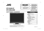
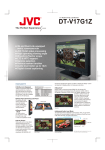
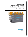
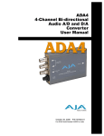
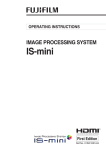
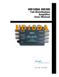
3GM
3G/1.5G HD-SDI
Multiplexer
User Manual
®
August 4, 2008
2
Trademarks
AJA®, KONA®, and XENA® are registered trademarks of AJA Video, Inc. Io HD™ and Io™ are
trademarks of AJA Video, Inc.
All other trademarks are the property of their respective holders.
Notice
Copyright © 2008 AJA Video, Inc. All rights reserved. All information in this manual is subject to
change without notice. No part of the document may be reproduced or transmitted in any form,
or by any means, electronic or mechanical, including photocopying or recording, without the
express written permission of AJA Inc.
FCC Emission Information
This equipment has been tested and found to comply with the limits for a Class A digital device,
pursuant to Part 15 of the FCC Rules. These limits are designed to provide reasonable protection
against harmful interference when the equipment is operated in a commercial environment. This
equipment generates, uses and can radiate radio frequency energy and, if not installed and used in
accordance with the instruction manual, may cause harmful interference to radio
communications. Operation of this equipment in a residential area is likely to cause harmful
interference in which case the user will be required to correct the interference at his own expense.
Changes or modifications not expressly approved by AJA Video can effect emission compliance
and could void the user’s authority to operate this equipment.
Contacting Support
To contact AJA Video for sales or support, use any of the following methods:
443 Crown Point Circle, Grass Valley, CA. 95945 USA
Telephone: 800.251.4224 or 530.274.2048
Fax: 530.274.9442
Web: http://www.aja.com
Support Email: [email protected]
Sales Email: [email protected]
When calling for support, have all information at hand prior to calling.
Limited Warranty
AJA Video warrants that this product will be free from defects in materials and workmanship for a period of five years from
the date of purchase. If a product proves to be defective during this warranty period, AJA Video, at its option, will either
repair the defective product without charge for parts and labor, or will provide a replacement in exchange for the defective
product.
In order to obtain service under this warranty, you the Customer, must notify AJA Video of the defect before the expiration
of the warranty period and make suitable arrangements for the performance of service. The Customer shall be responsible
for packaging and shipping the defective product to a designated service center nominated by AJA Video, with shipping
charges prepaid. AJA Video shall pay for the return of the product to the Customer if the shipment is to a location within
the country in which the AJA Video service center is located. Customer shall be responsible for paying all shipping charges,
insurance, duties, taxes, and any other charges for products returned to any other locations.
This warranty shall not apply to any defect, failure or damage caused by improper use or improper or inadequate
maintenance and care. AJA Video shall not be obligated to furnish service under this warranty a) to repair damage resulting
from attempts by personnel other than AJA Video representatives to install, repair or service the product, b) to repair
damage resulting from improper use or connection to incompatible equipment, c) to repair any damage or malfunction
caused by the use of non-AJA Video parts or supplies, or d) to service a product that has been modified or integrated with
other products when the effect of such a modification or integration increases the time or difficulty of servicing the
product.
THIS WARRANTY IS GIVEN BY AJA VIDEO IN LIEU OF ANY OTHER WARRANTIES, EXPRESS OR
IMPLIED. AJA VIDEO AND ITS VENDORS DISCLAIM ANY IMPLIED WARRANTIES OF
MERCHANTABILITY OR FITNESS FOR A PARTICULAR PURPOSE. AJA VIDEO’S RESPONSIBILITY TO
REPAIR OR REPLACE DEFECTIVE PRODUCTS IS THE WHOLE AND EXCLUSIVE REMEDY PROVIDED TO
THE CUSTOMER FOR ANY INDIRECT, SPECIAL, INCIDENTAL OR CONSEQUENTIAL DAMAGES
IRRESPECTIVE OF WHETHER AJA VIDEO OR THE VENDOR HAS ADVANCE NOTICE OF THE
POSSIBILITY OF SUCH DAMAGES.
AJA 3GM 3G/1.5G HD-SDI Multiplexer User Manual — Introduction
3
Introduction
The 3GM is versatile and economical tool for interconnecting dual-link 1.5G
SMPTE372M and 3G SMPTE425M. 3GM is bi-directional - allowing dual 1.5G to
3G or 3G to dual 1.5G conversion. Additionally, 3GM’s 3G HD-SDI output is
configurable for SMPTE425M type A or B. The 3GM can even convert 3G from/to
type A or B. 3GM also provides a monitor output which is a single link
SMPTE292M 1.5G HD-SDI. The 3GM is compatible with SMPTE259M 270Mb
SDI.
Features
1
• Compact 3G to/from 1.5G conversion
• SMPTE425M-AB inputs, 3G outputs configurable to A or B
• Converts SMPTE425M A to/from SMPTE425M B
• Provides SMPTE292 monitor output for dual 1.5G or 3G inputs
• Fully equalizing and re-clocking with jitter attenuation
• Passes all ancillary data
Block Diagram
SD-SDI, HD-SDI, or 3G-SDI
Input 1
SDI Receiver
SD-SDI or HD-SDI
Input 2
SDI Receiver
SDI Transmitter
SD-SDI, HD-SDI, or 3G-SDI
Output 1
SDI Transmitter
SD-SDI, HD-SDI, or 3G-SDI
Output 2
SDI Transmitter
SD-SDI or HD-SDI
Output Monitor
SDI
Processing
3GM, Simplified Block Diagram
I/O Connections
SD-SDI, HD-SDI, 3G-SDI
Link A (dual link) Output
SD-SDI, HD-SDI, 3G-SDI
Link A (dual link) Input
SD-SDI, HD-SDI, 3G-SDI
Link B (dual link) Output
Lock LED
SD-SDI or HD-SDI
Link B (dual link) Input
Green: Lock to SD
Red: Lock to HD/
Dual Link
Amber: Lock to 3G
SD-SDI or HD-SDI
Output Monitor
+ 5VDC
Power
Input
3GM Converter
4
User Controls
The user interface for the 3GM is an 8-position DIP switch
accessible through a cut-out in the bottom of the unit.
The exact function of each DIP switch and what it controls
is described on the following pages.
Switch 1—Selects Multiplex or Distribution
Amplifier (MODE)
DIP Switches
LEFT
RIGHT
OFF
ON
LEFT (MUX)
RIGHT (DA)
MUX:
Converts between Dual-link (SMPTE 372M)
and 3G (SMPTE 425M)
DA:
Places device in distribution amplifier mode.
A Dual-Link input results in a Dual-Link output
A Dual-Link input results in a 3G output
(mode A or B).
A 3G-SDI input (mode A or B) results in a
Dual-Link output
Note: In both cases, the monitor output will
be a downconverted HD (SMPTE 292M
compliant) output.
A 3G-SDI input results in a 3G output
(both in mode A or B)
Note: In both cases, the monitor output will be a
downconverted HD (SMPTE 292M compliant)
output.
Switch 2—Selects between 3G A or 3G B output map (when
device is set to output 3G)
LEFT (B)
RIGHT (A)
B:
Selects 3G B mapping. 3G output is set to
the B mapping structure.
A:
Selects 3G A mapping. 3G output is set to the A
mapping structure.
Switch 3—Manually select input signal color space: YCbCr/RGB
LEFT (YCbCr)
RIGHT (RGB)
YCbrCr:
If Dipswitch 8 is set to Manual or there is no
payload ID, the 3GM will behave as if the
input video is in the YC color space.
RGB:
If Dipswitch 8 is set to Manual or there is no
payload ID, the 3GM will behave as if the input
video is in the RGB color space.
If payload ID is present and Dipswitch 8 is
set to Auto, the 3GM uses the video
specifications in the payload ID.
If payload ID is present and Dipswitch 8 is set to
Auto, the 3GM uses the video specifications in the
payload ID.
AJA 3GM 3G/1.5G HD-SDI Multiplexer User Manual — User Controls
Switch 4 —Manually select the input signal bit depth: 10 or 12-bit
LEFT (10 Bit)
RIGHT (12 Bit)
10-Bit:
If Dipswitch 8 is set to Manual or there is no
payload ID, the 3GM will behave as if the
input video is 10-bit.
12-Bit:
If Dipswitch 8 is set to Manual or there is no
payload ID, the 3GM will behave as if the input
video is 12-bit.
If payload ID is present and Dipswitch 8 is
set to Auto, the 3GM uses the video
specifications in the payload ID.
If payload ID is present and Dipswitch 8 is set to
Auto, the 3GM uses the video specifications in the
payload ID.
Switch 5 —Select linear or log color (MON TYPE)
1
LEFT (LIN)
RIGHT (LOG)
LIN:
Configure input video as linear color.
Will colorspace convert and resample as
needed.
LOG:
Configure input video as logarithmic color.
Will perform a 10-bit Cineon to 8-bit linear
conversion before colorspace converting and
resampling the monitor output.
Note: Switches 5, 6, and 7 only affect the
monitor output.This switch has no effect on
primary outputs (linear or log color in results
in the same output)
Note: Switches 5, 6, and 7 only affect the monitor
output.This switch has no effect on primary
outputs (linear or log color in results in the same
output)
Switch 6 —Select SMPTE or FULL range color values for input
(MON RNG)
LEFT (SMPTE)
RIGHT (FULL)
SMPTE:
Defines input video as SMPTE color range
(040h-3ACh).
FULL:
Defines input video as FULL color range (004h3FBh).
Note: Switches 5, 6, and 7 only affect the
monitor output.This switch has no effect on
primary outputs (SMPTE in/ SMPTE out).
Note: Switches 5, 6, and 7 only affect the monitor
output.This switch has no effect on primary
outputs (FULL in/ FULL out).
Switch 7—Select between Video or Key for Monitor output
LEFT (Video, Input A)
RIGHT (Key, Input B)
VID/A:
For video input with an Alpha channel, this
sets the monitor output to Video in the case
of 4:4:4:4 video input.
KEY/B:
For video input with an Alpha channel, this sets
monitor output to the Alpha (key) in the case of
4:4:4:4 video input.
For video input without an Alpha channel,
this sets the monitor output to be Link A.
For video input without an Alpha channel, this sets
the monitor output to be Link B.
Note: Switches 5, 6, and 7 only affect the
monitor output.This switch has no effect on
primary outputs.
Note: Switches 5, 6, and 7 only affect the monitor
output.This switch has no effect on primary
outputs.
5
6
Switch 8—Select between Automatic or Manual Setup
LEFT (Auto)
RIGHT (Man)
AUTO:
If payload ID is present, the 3GM uses data
from the payload ID information to set color
space and bit depth (switches 3 and 4).
MAN:
The 3GM uses switches 3 and 4 for color space
and bit depth, regardless of whether payload ID is
present or not.
If payload ID is not present, the 3GM reverts
to switches 3 and 4 for input information.
Installation
In normal operation the 3GM uses between 4 and 6 watts of power. Because it is
designed to use the outer case and the attached cables for heat dissipation, the case
can feel warm to the touch. This is normal. Although the 3GM has been tested for
proper operation in an ambient temperature up to 45 degrees Celsius (113 F), it is
recommended to not position the 3GM in close proximity to other warm surfaces
or airflow.
To install, connect BNC cables to the desired source and destination devices and apply
+5VDC power to the converter (AJA power supply model DWP or DWP-U).
Specifications
Item
Specification
Video Inputs
2 HD-SDI, SDI (SMPTE 259/292/296/424), 2x BNC
Formats
3Gb, 1.5Gb, 270Mb Auto Select
Video Outputs
3G HD-SDI, HD-SDI, SDI, 3x BNC
Cable Equalization
270mb, 350m
1.5Gb, 200m
3Gb, 120m
Cable Equalization (1694 coax)
Input/Output Return Loss
>15db, 270Mb - 3Gb
User Controls
External Dipswitch
Size
4.6” x 2.4” x 1” (117 x 61 x 25mm)
Power
+5VDC, Regulated, 6 Watts
Requires Power Supply (AJA power supply model DWP or
DWP-U recommended)
Note: 3GM is not recommended for use with AJA DRM chassis rackmount kit.
AJA 3GM 3G/1.5G HD-SDI Multiplexer User Manual — Specifications
Dual Link to/from 3G level A Support
3G_A
Mapping Image Size
1
Color Space
Chroma
Convert Resample Image Size
Frame/Field Rates
4:2:2 YCbCr
10 bit
60, 60/1.001 and 50 progressive
1280x720
4:4:4:4 (RGB+A)
(A opt. )
(Note 1)
4:4:4:4 (YCbCr+A)
(A opt. )
(Note 1)
4:4:4:4 (RGB+A)
(A opt. )
(Note 1)
4:4:4:4 (YCbCr+A)
(A opt. )
(Note 1)
4:4:4 (RGB)
10 bit
60, 60/1.001 and 50 progressive
30, 30/1.001, 25, 24, 24/1.001 progressive
10 bit
60, 60/1.001 and 50 progressive
30, 30/1.001, 25, 24, 24/1.001 progressive
10 bit
60, 60/1.001 and 50 interlaced
30, 30/1.001, 25, 24, 24/1.001 progressive
10 bit
60, 60/1.001 and 50 interlaced
30, 30/1.001, 25, 24, 24/1.001 progressive
12 bit
60, 60/1.001 and 50 interlaced
30, 30/1.001, 25, 24, 24/1.001 progressive
1920x1080
2048x1080
4:4:4 (YCbCr)
12 bit
60, 60/1.001 and 50 interlaced
30, 30/1.001, 25, 24, 24/1.001 progressive
1920x1080
4:2:2:4 (YCbCr+A) 12 bit
(A opt. )
60, 60/1.001 and 50 interlaced
30, 30/1.001, 25, 24, 24/1.001 progressive
1920x1080
2048x1080
1920x1080
2048x1080
1920x1080
2048x1080
3
Pixel Depth
1920x1080
1280x720
2
in SMPTE
Video Formats
425M + 372M
Format 4
1920x1080
1: In all cases, A is 10-bit with an 8-bit payload.
Note
Note 2: 4:4:4 XYX monitoring is not supported.
KEY:
Yes
Yes
Yes
Monitor Output Formats
Frame/Field
Rates
Pixel Depth
Format
4: 2: 2 (YCbCr) 10 bit
60, 60/1.001 and 50 interlaced
Yes
1280x720
4:2:2 (YCbCr)
4: 2: 2 (A opt.)
10 bit
60, 60/1.001 and 50 progressive
30, 30/1.001, 25, 24, 24/1.001 progressive
Yes
1280x720
4: 2: 2 (YCbCr)
4: 2: 2 (A opt.)
10 bit
60, 60/1.001 and 50 progressive
30, 30/1.001, 25, 24, 24/1.001 progressive
Yes
1920x1080
2048x1080
4: 2: 2 (YCbCr)
4: 2: 2 (A opt.)
10 bit
60, 60/1.001 and 50 interlaced
30, 30/1.001, 25, 24, 24/1.001 progressive
Yes
1920x1080
2048x1080
4: 2: 2 (YCbCr)
4: 2: 2 (A opt.)
10 bit
60, 60/1.001 and 50 interlaced
30, 30/1.001, 25, 24, 24/1.001 progressive
Yes
1920x1080
2048x1080
4: 2: 2 (YCbCr)
10 bit
60, 60/1.001 and 50 interlaced
30, 30/1.001, 25, 24, 24/1.001 progressive
Yes
1920x1080
2048x1080
4: 2: 2 (YCbCr)
10 bit
60, 60/1.001 and 50 interlaced
30, 30/1.001, 25, 24, 24/1.001 progressive
1920x1080
4: 2: 2 (YCbCr)
4: 2: 2 (A opt.)
10 bit
60, 60/1.001 and 50 interlaced
30, 30/1.001, 25, 24, 24/1.001 progressive
1
Not Supported
Only supported in with payload ID
Dual Link to/from 3G level B Support
3G_B
Mapping Image Size
1
1920x1080
1280x720
4:4:4 (YCbCr)
1920x1080
1920x1080
2048x1080
4
Pixel Depth
1920x1080
2048x1080
1920x1080
2048x1080
1920x1080
2048x1080
3
Format
4:2:2 YCbCr
4:4:4:4 (RGB+A)
(A opt. )
(Note 1)
4:4:4:4 (YCbCr+A)
(A opt. )
(Note 1)
4:4:4:4 (RGB+A)
(A opt. )
(Note 1)
4:4:4:4 (YCbCr+A)
(A opt. )
(Note 1)
4:4:4 (RGB)
1280x720
2
Video Formats in SMPTE 425M + 372M
10 bit
Color Space
Chroma
Convert Resample Image
Size
Frame/Field Rates
60, 60/1.001 and 50 progressive
1920x1080
10 bit
60, 60/1.001 and 50 progressive
30, 30/1.001, 25, 24, 24/1.001 progressive
10 bit
60, 60/1.001 and 50 progressive
30, 30/1.001, 25, 24, 24/1.001 progressive
10 bit
60, 60/1.001 and 50 interlaced
30, 30/1.001, 25, 24, 24/1.001 progressive
10 bit
60, 60/1.001 and 50 interlaced
30, 30/1.001, 25, 24, 24/1.001 progressive
12 bit
60, 60/1.001 and 50 interlaced
30, 30/1.001, 25, 24, 24/1.001 progressive
12 bit
60, 60/1.001 and 50 interlaced
30, 30/1.001, 25, 24, 24/1.001 progressive
4:2:2:4 (YCbCr+A) 12 bit
(A opt. )
60, 60/1.001 and 50 interlaced
30, 30/1.001, 25, 24, 24/1.001 progressive
Note 1: In all cases, A is 10-bit with an 8-bit payload.
Note 2: 4:4:4 XYX monitoring is not supported.
Yes
Yes
Yes
Monitor Output Formats
Frame/Field
Rates
Pixel Depth
Format
4:2:2 (YCbCr) 10 bit
60, 60/1.001 and 50 interlaced
Yes
1280x720
4:2:2 (YCbCr)
4:2:2 (A opt.)
10 bit
60, 60/1.001 and 50 progressive
30, 30/1.001, 25, 24, 24/1.001 progressive
Yes
1280x720
4:2:2 (YCbCr)
4:2:2 (A opt.)
10 bit
60, 60/1.001 and 50 progressive
30, 30/1.001, 25, 24, 24/1.001 progressive
Yes
1920x1080
2048x1080
4:2:2 (YCbCr)
4:2:2 (A opt.)
10 bit
60, 60/1.001 and 50 interlaced
30, 30/1.001, 25, 24, 24/1.001 progressive
Yes
1920x1080
2048x1080
4:2:2 (YCbCr)
4:2:2 (A opt.)
10 bit
60, 60/1.001 and 50 interlaced
30, 30/1.001, 25, 24, 24/1.001 progressive
Yes
1920x1080
2048x1080
4:2:2 (YCbCr)
10 bit
60, 60/1.001 and 50 interlaced
30, 30/1.001, 25, 24, 24/1.001 progressive
Yes
1920x1080
2048x1080
4:2:2 (YCbCr)
10 bit
60, 60/1.001 and 50 interlaced
30, 30/1.001, 25, 24, 24/1.001 progressive
1920x1080
4:2:2 (YCbCr)
4:2:2 (A opt.)
10 bit
60, 60/1.001 and 50 interlaced
30, 30/1.001, 25, 24, 24/1.001 progressive
KEY: Not Supported
Only supported in with payload ID
7
8