1
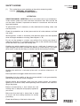
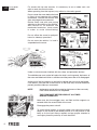
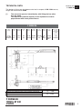
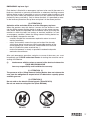
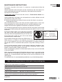
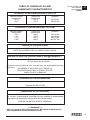
FASSI CRANE
cI
F 330SE.24 G.C.
use and maintenance
FROM SERIAL NUMBER *5151*
INDEX
Chapter
Edition 24.04.2008
I
INTRODUCTION
page
2
II
SAFETY NORMS
page
3
III
INSTRUCTIONS FOR CRANE USE
page
7
IV
IDENTIFICATION OF THE CRANE MODEL
page
8
V
TECHNICAL DATA
page
9
VI
CRANE NOMENCLATURE
page 12
VII
SAFETY AND PROTECTION DEVICES
page 14
VIII
LIFTING MOMENT LIMITING DEVICE
page 16
IX
CONTROLS TO STABILIZE THE VEHICLE
page 18
X
CONTROLS TO OPERATE THE CRANE
page 21
XI
USE OF IMPLEMENTS
page 24
XII
MAINTENANCE INSTRUCTIONS
page 25
XIII
POSSIBLE FAULTS
page 30
XIV
HYDRAULIC AND ELECTRIC SCHEMATICS
page 31
XV
OIL AND LUBRICANT CHARACTERISTICS
page 33
A
INSTRUCTION AND WARNING PLATES
page 34
B
CAPACITY PLATES
page 37
1
cI
INTRODUCTION
F 330SE.24
FASSI CRANE
F 330SE.24 G.C.
use and maintenance
This instruction manual describes the FASSI CRANE F330SE.24 G.C.
The fitment must be carried out in accordance with the instructions given
by the Manufacturer in the manual for hydraulic crane fitting.
The Manufacturer declines all responsibility and guarantee if the fitting is
entrusted to workshops without sufficient technical capability to carry out
the work in conformity.
As well as the principal safety norms, this manual contains a description of
the crane and the instructions for use and maintenance.
The crane must only be operated by responsible persons, previously
instructed and authorized.
THANK YOU FOR SELECTING ONE OF OUR CRANES.
2
SAFETY NORMS
(!)
SAFETY NORMS
F 330SE
c II
This symbol draws your attention on the points concerning safety.
It means: WARNING! BE CAREFUL!
IT CONCERNS YOUR SAFETY!
!ATTENTION!
READ THIS MANUAL CAREFULLY prior to use of the crane or any maintenance.
A few minutes spent now could save time and labour later. Be sure that the
unit has been installed, inspected and tested in accordance with the local
legal requirements.
To operate the crane it is necessary to fully understand its working, safety and
warranty norms.
Check that protections are in their place and that all safety devices are fitted
and active.
Warning plates, as well as instruction and operation plates must be replaced
when no longer readable or missing. (See chapters A - B)
Do not run the engine in a indoor area without first making sure there is
adequate ventilation. Fit a suitable extension tube to the vehicle exhaust pipe
to take the fumes away from the working area.
Stabilize the vehicle checking that they rest on a solid base; if necessary use
larger outrigger base plates (available on request) to avoid sinking. If you adopt
other means, make sure that they are suitably sized for the load they must bear.
Stabilize the vehicle on a horizontal plane with a maximum tolerance of 1,5
degrees.
Never operate the outriggers when the crane is loaded.
Remember that the stability of the unit (crane-vehicle) is only guaranteed by
the fully lateral extension of the outriggers.
Should visibility be insufficient, make sure that control stations are properly
lighted so as to ensure safety while operating control functions and allow reading of the plates.
Before manoeuvering a load check that the
working area is adequate and properly lighted for
your crane.
Make sure that the hook is always free to rotate
on its pin and that nothing obstructs its vertical
positioning.
Check the efficiency of the hook safety catch.
3
c II
SAFETY NORMS
F 330SE
Carefully inspect the load rigging and the condition of ropes or chains.
Make sure that the lifted load is balanced.
Hook up the load, checking that it does not
exceed the capacity indicated on the lifting
diagram specific to each load configuration.
It is absolutely prohibited to walk or stop under a suspended load and for unauthorized persons to be within the working area.
Avoid swinging the load above the control station; any hidden danger situation
must be audibly alarmed.
Avoid all those situations which may result in crushing during crane stabilization,
movement and load handling.
The table reports the minimum safe working distances to avoid crushing parts of
the body.
Parts
of the
Body
Minimum safe
working
distance mm
Figure
Parts
of the
Body
Minimum safe
working
distance mm
Body
500
Head
300
Leg
180
Foot
120
Toes
50
Arm
120
Hand
Wrist
Fist
100
Finger
25
Figure
In conformity with “EN 349” Standard the minimum safe working distances to avoid crushing parts of the body.
4
NOTE: Failure to respect the minimum safe distances may result in a
deadly risk for the operator and his assistants.
Maintain safe clearances from electrical lines
and apparatus. You must allow for boom sway,
rock or sag and electrical line and loadline
swaying. This lifting device does not provide
protection from contact with or proximity to an
electrically charged conductor. You must maintain a clearance of at least 10 feet between
any part of the crane, loadline or load and any
electrical line or apparatus carrying up to 50.000
volts. One foot additional clearance is required
for every additional 30.000 volts or less.
SAFETY NORMS
F 330SE
c II
NOTE: Failure to respect the minimum safe distances may result in electrical
hazards for the operator and his assistants.
Do not utilize the crane with stormy weather or with wind speed exceeding
12,5 m\s (value 6 of the Beaufort scale).
Indications about wind speed
Force of the
wind
Beaufort scale
Wind speed Classification
m/s
Characteristics
0
0,0 - 0,2
Calm
Calm wind, smoke
goes up quite vertically
1
2
0,3 - 1,5
1,6 - 3,3
Light breeze
Smoke reveals the
direction of the wind,
one can feel the wind
blowing, leaves start
fluttering.
3
4
3,4 - 5,4
5,5 - 7,9
Moderate breeze
Leaves and branches
are in constant motion,
small branches start
fluttering. Dust and
papers dance on the
ground.
5
8,0 - 10,7
Fresh breeze
Small green branches
bend, the surface of
waterways and lakes
are wavy.
6
10,8 - 13,8
Near gale
Big branches bend,
wind whistles through
high-tension cables,
it's difficult to walk
keeping the umbrella
open.
7
13,9 - 17,1
Moderate gale
Trees sway, it's hard
to walk.
8
17,2 - 20,7
Storm wind
Branches get broken,
it's hard to walk.
9
20,8 - 24,4
Storm
It damages houses
(antennas and roof tiles
fall down)
5
c II
SAFETY NORMS
F 330SE
For cranes with top seat controls, it is necessary to use a ladder and a cat
walk to reach the control station.
When operating from the top seat, stay within its side safety guards.
Do not rotate the crane before the load
is lifted, do not operate with sudden
movements, activate the controls with
slow and progressive movements.
Rotate slowly and with care paying
attention to the stability of the vehicle.
With vertical lift, on hydraulic and
mechanical extension, rotate slowly
in order to avoid side-skidding.
Do not utilize the crane for pushpull,
lateral or sideways operations.
Do not move the vehicle if a load is
suspended on the crane.
Under no circumstances interfere with the safety and protection devices.
The vehicle\crane must not be left unless the load is on the ground, the booms of
the crane are folded and laid on a solid base and the power take-off is disengaged.
At the end of the job and prior to driving the vehicle the crane must be folded.
If the booms are to be laid on the body or on the load, they must be blocked to
prevent possible sideways movements.
NOTE
Implements can be left mounted on the booms of the crane only
if the overall dimensions are respected.
THE FORK MUST BE TIED DOWN AT ALL TIMES
DURING TRANSPORT
Make sure that the outrigger rams are lifted and the supports reentered within the overall width of the truck.
Disengage the power take off.
To avoid hitting bridges or tunnels check and record the overall
height of your crane in the folded position or in laid position in the
body or on the load. Always respect and pay proper attention to
road signs placed in proximity of such obstacles.
6
INSTRUCTIONS
FOR CRANE USE
INSTRUCTIONS FOR CRANE USE
F 330SE
The use of the crane is reserved to authorized personnel, instructed in
advance, who has to strictly conform to the safety norms and instructions contained in the instruction manual supplied with the crane.
c III
1 — Only authorized persons are allowed to operate the crane.
2 — The crane must be used on firm, level ground.
3 — Check that the vehicle hand brake is on and that the wheels are chocked.
4 — Before every operation make sure that:
— no-one is within the working area of the crane;
— the safety devices are in place and operative;
— the minimum safe working distances from power lines are observed;
— the load is correctly slung and hooked.
5 — Stabilize the vehicle by the outrigger rams, making sure that:
— the lateral supports are fully extended;
— the wheels are in contact with the ground and the suspension is not
completely unloaded;
6 — Use the crane in accordance with the use and maintenance manual,
making sure that:
— the load and radius are within the maximum limits shown on the
crane capacity plate;
— the crane is used progressively avoiding sudden load movements;
— swinging or dragging of the load is avoided;
— the load is lifted before rotating.
7 — When using implements protect the crane working area with a barrier.
8 — The vehicle/crane are not left unless the power take off is disengaged
and the load is on the ground.
9 — Before driving the vehicle make sure that the outriggers are fully retracted
and re-entered, and the crane is in folded position.
fig. 1
THESE INSTRUCTIONS FOR THE USE OF THE CRANE COINCIDE WITH THOSE OF THE
PLATE DE2676 (FIG. 1) PLACED NEXT TO THE CRANE.
7
c IV
IDENTIFICATION OF
THE CRANE MODEL
IDENTIFICATION OF THE CRANE MODEL
F 330SE
The exact crane model, serial number and description of implements will
enable FASSI Service Department to give a rapid and efficient response.
Identification data of the crane are marked on the plate DE2141 and fixed on
the base.
1
1 — Crane model
2 — Serial Number
3 — Year of manufacturing
2
3
(!)
8
UNDER NO CIRCUMSTANCES SHOULD THE DATA MARKED
ON THE PLATE BE ALTERED.
TECHNICAL DATA
TECHNICAL DATA
F 330SE.24
cV
The design of this crane has been carried out in respect of DIN 15018 norms,
fatigue test classification H1B3 .
(!)
The crane can operate, intermittently, with lifting devices other
than the hook.
The dimensions and the capacity of the implements must be
proportioned with crane performances.
F 330SE.24
Lifting
capacity
Standard
reach
Hydraulic
extension
Rotation
arc
Rotation
torque
Working
pressure
18,6 tm
182,5 kNm
17,9 m
9,54 m
400°
4,69 tm
25,0 MPa
134605 lbf.ft
58’9”
31’4”
400°
33927 lbf.ft
3625 psi
Pump
capacity
Oil tank
capacity
60+60 l/min
180 l
46 kNm
16+16
PESO GRU CON SERBATOIO NON RIFORNITO, STABILIZZATORI STANDARD
WEIGHT OF THE CRANE WITH EMPTY TANK, STANDARD STABILIZATION
POIDS DE LA GRUE AVEC RESERVOIR VIDE, STABILISATION STANDARD
KRANGEWICHT MIT LEEREM TANK UND STANDARDABSTUETZUNG
48 gals
Crane
weight
Max. working
pressure
on the outrigger
() 500)
() 1’7”)
4800 kg
10582 lbs
gal/min
kg
120 psi
8,3 daN/cm2
4.800
lbs 10.582
F 330SE.24
ST 331
9
cV
TECHNICAL DATA
F 330SE
F 330SE
ST 331
10
TECHNICAL DATA
F 330SE
F 330SE
cV
MASSIMA ALTEZZA SOTTOGANCIO.
HAUTEUR MAXIMUM SOUS CROCHET.
MAXIMUM HOOKING POSITION.
MAXIMALHOEHE BIS KRANHAKEN
ST 331
11
c VI
CRANE
NOMENCLATURE
CRANE NOMENCLATURE (fig. 2)
F 330SE
Pos.
1
2
3
4
5
6
7
8
9
10
11
12
13
14
15
16
17
18
19
12
Description
-
Outrigger rams
Outrigger supports
Base
Rotation cylinders
Column
Inner ram
Inner boom
Outer ram
Outer boom
Booms extension rams
Extension boom sections
Deviator crane - outriggers
Distributor for outriggers
Dual control for deviator crane - outriggers
Outrigger multifunctions transmission
Supplementary hoses (hydraulic implements)
Oil tank
Distributors for crane
Double control for crane distributors
CRANE
NOMENCLATURE
F 330SE
c VI
fig. 2
13
c VII
SAFETY AND
PROTECTION DEVICES
SAFETY AND PROTECTION DEVICES (fig. 3)
F 330SE
Pos.
1
2
3
4
5
6
7
8
9
10
11
12
13
14
15
Description
-
Check valves for outrigger rams
Check valve for rotation control
Check valve for inner ram
Check valve for outer ram
Check valve for booms extension rams
Lifting moment limiting device assembly
Parachute valves (lifting moment limiting device)
Main pressure valve (outrigger distributor)
Main pressure and auxiliary valves (crane distributors)
Carter for outer ram
Carter for hose protection devices
Carter for booms extensions ram check valve
Levers guard
Emergency tap (lifting moment limiting device)
Heat exchanger
(!) Before crane use check that safety and protection devices are fitted
and active.
(!) Under no circumstances interfere with the safety and protection devices.
(!) Interference with the check valves and removal of the lead seals remove
the Manufacturer and invalidate the warranty.
14
SAFETY AND
PROTECTION DEVICES
F 330SE
c VII
fig. 3
15
c VIII
LIFTING MOMENT
LIMITING DEVICE
F 330SE
LIFTING MOMENT LIMITING DEVICE
A characteristic which permits the classification of cranes is their lifting capacity or maximum lifting moment. The moment is defined by the value obtained
from the product of the load to be lifted (in lbs) by its distance (in ft) from the
centerline of the crane rotation.
The device called “lifting moment limiting device” preserves the crane structure
from overloads, as it prevents any movement which increases the value of the
moment up to the maximum established value.
Lifting moment limiting device “INTELLIGENT TYPE”
This device utilises an electrohydraulic technology, preventing any movement
which causes an increase in the pressure induced by the load in the inner and
outer rams of the crane, up to the “critical values”. These values, which are
non-exceedable, determine the intervention levels and
provide the data for setting the device.
fig. 4
fig. 5
The lifting moment limiting device concernes the following manoeuvres:
- Inner boom descent; the inner boom lift is controlled
by the general main pressure valve of the distributor.
- Outer boom lift.
- Outer boom descent.
- Extension of extension boom sections.
The system uses the specific functions of the distributor by
utilising an electro-hydraulic technology, it does not allow
you exceed the set value, by disactivating the controls
(levers in neutral position) commanded by the limiting device. The condition of intervention is operated by the position of the outer boom (or, if hydraulic extension is fitted,
the position of the extension outer boom), on which the
electronic signal position (mercury level switch) is read by
a special electrovalve. This determines controls which are
locking or unlocking (resetting) of the controls concerned.
When the moment is reduced, it resets automatically (the
manoeuvres blocked by the device are released). N.B.: There is a delay of
four (4) seconds after the moment reduction before the reset can occur in
order to safeguard the stability of the device.
The crane configurations (fig. 4-5) indicate the manoeuvres which are allowed
and not allowed by the device, in connection with the horizontal position of
the crane and extension outer booms. When the moment is reduced, it resets
automatically (the manoeuvres blocked by the device are released).
(!) CAUTION DANGER (!)
On the outer boom there is a mercury capsule (mercury level
switch) duly protected and provided with the following warning
stickers.
MERCURY IS EXTREMELY TOXIC. IN CASE OF REPLACEMENT AND/OR SCRAPPING, DISPOSE OF OR RECYCLE THE
CAPSULE CONTAINING MERCURY WITH MAXIMUM CARE,
AND IN ACCORDANCE WITH THE NATIONAL REGULATIONS
IN FORCE.
(!)
16
In the absence of electric power all crane functions will be
desactivated.
EMERGENCY tap lever fig. 6
LIFTING MOMENT
LIMITING DEVICE
Each device is fitted with an emergency tap lever to be used in the event of a
black-out, electrical or hydraulic malfunctions or whenever the lifting moment
limiting device makes it impossible to use any controls when handling a load
(this may occur when the extension booms are fully folded and the load is
particularly heavy and bulky). Only In these situations it is permitted to remove the lead seal placed on the tap lever and place it in the closed position.
(!) ATTENTION (!)
Activation of the exclusion device or of the emergency tap lever.
When the operator uses this device, it means that he wishes to override the lifting moment limiting device in order to make some manoeuvres (which would be impossible with the device active) that bring the
moment to within the level, but involve an overload condition. In such
an emergency condition (where the lifting moment limiting device has
been disabled), the operator must be:
- carefully consider the manoeuvres required to return to normal
working conditions;
- calmly and carefully assess the type and scale of the hazards
arising from these manoeuvres and the possible reaction of the
crane (tipping over, frame overload, uncontrolled fall of the load
due to a hydraulic system overload etc...);
- make all movements as slowly as possible to reduce the dynamic
overload to the minimum.
F 330SE
c VIII
fig. 6
After such emergency operations and prior to re-use of the crane, you must
immediately go to FASSI authorised Center for testing the structure and resealing of the device.
(!)
Interferences with the valves or removal of the lead seal release the
FASSI GRU IDRAULICHE
from any responsibility and invalidate the warranty.
(!) ATTENTION (!)
The presence of the lifting moment limiting device does not release the
user from the obligation to respect what is indicated on capacity plates
and lifting curves.
(!) ATTENTION (!)
Do not walk on the electric control panels. (Plate DE1679)
Do not use water to estinguish fire! (Plate DE1680)
DE1679
DE1680
17
c IX
CONTROLS
TO STABILIZE
THE VEHICLE
F 330SE
CONTROLS TO STABILIZE THE VEHICLE
The outriggers rams prevent harmful stresses both to the frame and to the vehicle
suspensions on which the crane is mounted and assure the stability of the unit during
load handling.
Be very careful during vehicle stabilization operation; make sure that no one is or transits in close proximity of the working area of the outriggers specially in the case that the
outrigger controls is executed from the opposite side of the vehicle (it is not possible
visually check the operation).
(!) ATTENTION (!)
The crane stability is maintained by the maximum extension of the outrigger supports, by the solidity of the base underneath the plates of the outrigger rams and
by the observance of the capacity plates. To check the maximum working pressure
see Paragraph D0.1 Technical data.
Check that the outrigger rams are applied on a solid base; if necessary use larger
outrigger base plates (available on request) to avoid sinking.
When stabilization is complete the wheels of the vehicle must still be in contact with
the ground and the suspensions must not be fully unloaded.
Stabilize the crane so as to operate on a horizontal plane with a maximum tolerance of
1,5 degrees.
While loading, it may be necessary to vertically adjust the outrigger rams to prevent an
overload on the outriggers, then stabilize again.
While unloading, the outrigger rams may not be perfectly in contact with the ground
because of a rise in the suspension; it is therefore recommended to stabilize the vehicle during operation to avoid an overturn.
Functions of control levers for stabilization
The controls to stabilize the vehicle are activated only from ground level and on both
sides of the crane base.
NOTE
The graphic symbols illustrated hereunder are marked on the plates (DE4486DE4487-DE4485-DE4497-DE4488-DE4489) affixed next to the control stations and
indicate with the following symbolism.
They indicate the position of the operator in
relation to the vehicle and the crane.
Lever CD for selecting
outrigger ram
or
outrigger support
Levers D
Deviator
Lever C to control
outrigger support
or
outrigger ram
See Paragraph R0 Instruction and warning plates.
Lever function D - CD - C
Levers D
Control for deviator crane-outriggers ( - E\S ).
Levers CD Control for selecting the supports or the outrigger rams.
Levers C
Control for the support or the outrigger ram selected
18
-E/S
CONTROLS
TO STABILIZE
THE VEHICLE
The "multifunction" control group adopted allows to select and manoeuvre the outrigger support or the ram, through simultaneous operation of the selecting lever CD and
the control lever C.
CD
Exemple
To select the support E2 or the outrigger ram S2
- Position the lever CD (corresponding to outrigger
support E2 and to outrigger ram S2) on E2 or S2 and
keep it in position.
To carry out the operation
- Operate lever C to activate the exit/re-entry of outrigger
support E2 or the descent/lift of outrigger ram S2.
c IX
F 330SE
D
C
Special base plates (detachable)
The outrigger rams of the crane and of the supplementary outriggers they are supplied with base plates which can be fastened to the ram stems through jaw securing
devices.
Fastening of the base plate
- Place the base plate underneath the ram, remove the check pin
and open the anchor jaws. (fig.10-10a)
- Operate the corresponding lever S to control the descent of the ram
until the ball joint touches the seat cut in the base plate; close the
jaws and secure them in their seat with the check pin. (fig. 10b-10c)
fig. 10
fig. 10a
fig. 10b
fig. 10c
Removal of the base plate
- Release the check pin and open the anchor jaws.
- Operate the corresponding lever S to control the re-entry of the ram.
- Close the jaws, secure them with the check pin and remove the
base plate.
(!) For the safety and for the encumbrances we recommend to
remove the plates before putting the rams to the rest position;
special handles are featured for the plates handling and the
opening and closing of the securing device (jaws).
(!) WARNING (!)
Keep clean the ball joint heads of the outrigger rams and the seats cut in the
base plates to avoid their deterioration.
fig. 12
Controls to stabilize the vehicle
fig. 13
Controls for positioning the outriggers of the crane and the supplementary beam.
(!) WARNING (!)
Due to the special construction of the hydraulic circuit (double circuit with two pumps)
the distributor placed on the right of the operator (rotator control, outer ram and crane
rotation) is alimented by one pump also with the lever D of oil-diverter crane-outriggers
( - E/S) on E/S.
The controls are activated on both sides, on crane distributors side (DE4485 fig. 12) or
on crane double controls side (DE4497 fig. 13)
(!) ATTENTION (!)
When controlling the outriggers from the opposite side of the vehicle (it is not
possible visually check the operation) make sure that no one is or transits in
close proximity of the working area of the outriggers. (Fig. 11 plate DE2497 and
fig. 12 plate DE2498)
fig. 11
fig. 12
19
c IX
CONTROLS
TO STABILIZE
THE VEHICLE
F 330SE
(!) ATTENTION (!)
Operation of the crane outrigger supports must be from the control station
on that side; it is not allowed to operate outriggers on the opposite side of
the vehicle due to unseen dangers. DE4491
See Paragraph "Special base plates" for details of the fastening of the base
plates on the outrigger rams.
Position lever D of oil diverter (
-E/S) on E/S. DE4488
How to exit the outrigger support E2 (crane)
- Operate the corresponding lever CD towards right (E2) and keep it in position.
- Operate the lever C towards right to exit the outrigger support.
How to descent the outrigger ram S2 (crane)
- Operate the corresponding lever CD towards left (S2) and keep it in position.
- Operate the lever C towards right to descent the outrigger ram.
How to exit the outrigger support E3 (supplementary outriggers)
- Operate the corresponding lever CD towards right (E3) and keep it in position.
- Operate the lever C towards right to exit the outrigger support.
How to descent the outrigger ram S3 (supplementary outriggers)
- Operate the corresponding lever CD towards left (S3) and keep it in position.
- Operate the lever C to descent the outrigger ram.
How to exit the outrigger support E1 (crane)
- Operate the corresponding lever CD towards right (E1) and keep it in position.
- Operate the lever C towards right to exit the outrigger support.
How to descent the outrigger ram S1 (crane)
- Operate the corresponding lever CD towards left (S1) and keep it in position.
- Operate the lever C towards right to lift the outrigger ram.
How to exit the outrigger support E4 (supplementary outriggers)
- Operate the corresponding lever CD towards right (E4) and keep it in position.
- Operate the lever C to exit the outrigger support.
How to descent the outrigger ram S4 (supplementary outriggers)
- Operate the corresponding lever CD towards left (S4) and keep it in position.
- Operate the lever C to descent the outrigger ram.
(!) ATTENTION (!)
The complete extension of the outrigger supports is visually indicated by the yellow
triangles which are found at the end of the beam (and of the support if it’s supplied
with extra double extension beams).
The stabilization has to be carried out with care and gradually keeping the vehicle in
horizontal levelled condition to prevent springs overloads and chassis torsions.
(!) ATTENTION (!)
During the stabilising operations, for each outrigger ram, it is recommended to
DESCENT the outrigger as the last manoeuvre.
To operate the crane controls, after having completed the descent and stabilisation manoeuvres,
- Position lever D of oil diverter ( - E/S) on
.
Manoeuvres for re-entry of the crane outriggers and supplementary outriggers
within the overall vehicle width after crane use.
Position lever D of oil diverter (
- E/S) on E/S.
See Paragraph "Special base plates" for details of the removal of the base plates from
the outrigger rams.
How to lift the outrigger ram S
- Operate the corresponding lever CD towards left (S) and keep it in position.
- Operate the lever C towards left to lift the outrigger ram.
How to re-enter the outrigger support E
- Operate the corresponding lever CD towards right (E) and keep it in position.
- Operate the lever C towards left to re-enter the support.
20
(!) WARNING (!)
Assure that the outrigger supports and rams are completely re-entered before
moving the vehicle.
CONTROLS
TO OPERATE
THE CRANE
CONTROLS TO OPERATE THE CRANE
(!) WARNING (!)
Before operating the crane it is compulsory to set the outriggers.
cX
F 330SE
This coincides with that indicated on the plate DE6723 placed on the outriggers.
Fig. 13
(!) Operate the levers smoothly and gradually.
Hydraulic implements and crane controls
The control stations are on base-plate; the crane and the hydraulic implements controls are bilateral, manual and sequential type.
The crane adoptes Danfoss distributors manual control with electric modulars
for remote controls and emergency electro-valve manual block.
(!) WARNING (!)
In the absence of electric power all crane functions will be desactivated.
Distributor side
The left distributor, respect to the operator, control three functions (left to right):
Pallet-fork
Extension
booms
fig. 13
Outer
boom
The right distributor, respect to the operator, control three functions (left to right):
Fork
rotator
Inner
boom
Crane
rotation
Double control side
The levers control (left to right, respect to the operator)
Pallet-fork
Extension
booms
Outer
boom
Fork
rotator
Inner
Inner
Crane
rotation
The symbols placed over each lever define their function in relation to their
movement.
(!)
First read the instructions given in the User’s Manual supplied
by the Manufacturer before using the remote control to avoid
improper use.
21
cX
CONTROLS
TO OPERATE
THE CRANE
F 330SE
Manoeuvres to unfold the crane into a working condition
— Engage the power take off.
— Stabilize the vehicle as described on Chapter IX.
— Before lifting the inner boom, be sure that the outer ram is completely open.
— Lift the inner boom over the horizontal line, close the outer boom and eventually extend the booms of the crane.
— Operate on the crane rotation to position the pallet-fork on the vertical line
above the load, operate on the pallet-fork rotation control (rotator) for the
correct orientation of the fork.
Manoeuvres to fold the crane into the rest condition
— Open the outer boom to its stroke end.
— Re-enter the extension boom sections.
— Operate the rotation control of the crane and fold the inner boom, paying
attention to the crane boom position on the body. It is necesssary during
this operation to orientate the pallet-fork position to avoid obstacles on the
body or the load.
— Lift and re-enter the outriggers as described.
— Disengage the power take off.
(!) In case of implements on the load or the truck body it is necessary to
check they are locked to assure the impossibility of accidental
movements.
(!) THE FORK MUST BE TIED DOWN AT ALL TIMES DURING TRANSPORT
Emergency restoration buttons of the distributors functions with power
failure. Fig. 14
(!) WARNING (!)
Operating the locking device of the electro-valve connected
in every distributors allowes the operator to manoeuvre only
and exclusively in case of power failure.
The locking device of the electro-valve is instable and allowes
to restore the distributor functions operating with two hands;
you must keep pressed the device and at the same time
operate on the distributor lever in order to effect the stability
manoeuvre.
fig. 14
22
These buttons must only be used in an emergency and
only to bring the crane to its rest position.
Load manoeuvres
(!)
Before manoeuvering the load, verify that the working area is
suitable for your crane.
CONTROLS
TO OPERATE
THE CRANE
cX
F 330SE
The lifting curves of the capacity chart indicate the maximum load that the
crane can lift at a certain radius and at a certain height.
(!) Always remember that when operating with implements, their tare
weight must be deducted from the capacity of the crane.
During load handling do not exceed the reach limits given, or the load
indicated on the above mentioned charts. If the limits are exceeded, the
lifting moment limiting device, allowing all manoeuvres, which reduce the lifted load within the permitted reach limits and forbid all other
manoeuvres, will be immediately activated.
(!)
The presence of the lifting moment limiting device does not release
the user from the observance of the capacity chart.
23
c XI
USE OF IMPLEMENTS
F 330SE
USE OF IMPLEMENTS
OIL COOLER (HEAT EXCHANGER)
The crane can be equipped with an oil cooler (air-oil heat exchanger) to prevent
damage caused by an excessive increase of the oil temperature.
NOTE
When working in a low temperature climate, we recommend to bring the
hydraulic oil up to working temperature prior to starting work, This is best
done by operating the crane thru all its functions ram stroke end.
(!) WARNING (!)
The heat exchanger openings must be kept clear and clean. At no time should
it be covered.
HYDRAULIC ACCESSORIES
The crane can be provided with implements such as:
- Fork rotator
- Pallet-fork
(!)
When using an implement it is always necessary to check that its weight,
dimension and capacity is matched to the crane performances.
(!)
Warning and norms for crane use also apply for hydraulic implement use.
(!)
Always remember that when operating with implements, their tare weight
must be deducted from the capacity of the crane.
Hydraulic connections between implements and hoses fitted on the
extension boom section of the crane.
(!)
In case of hoses connection to implements through coupling unions it is
necessary to verify that there is no trace of soil, curt etc. on the unions
and inside the seats so as to avoid the oil contamination and consequently wear the tightening “ surface of unions.
(!) WARNING (!)
To ensure that the control corresponds to the implement movement, hydraulic
connections are symmetrically fitted with coupling unions. Never invert such
positions: movements inversion as well as operating difficulties could occur.
24
MAINTENANCE
INSTRUCTIONS
MAINTENANCE INSTRUCTIONS
To assure a long life to the crane, it is necessary to meticulously follow the
instructions.
F 330SE
c XII
General lubrication and small repairs can be carried out by the user; repairs of a
more complicated nature must be carried out by authorized service personnel.
Spare parts must be original.
At least once a year you must take the crane to a Fassi Service Center for a
check.
Good maintenance and proper use are imperative to maintain efficient use and
guarantee the safety of the crane.
(!) Before disconnecting any hydraulic hoses, ensure that there is no pressure
in the hydraulic circuit.
After removing hoses always mark them and their respective ports on the crane.
Faulty replacement can cause damage to the rams and to the hydraulic circuit.
Respect the information supplied for maintenance and technical assistance.
Any maintenance operation must be carried out with the crane power source turned
off. (in case of fixed mounting with hydraulic power pack, the electric motor has to be
turned off).
Do not place limbs, fingers or any other parts of anatomy
into areas of the crane, which present possibilities of
shearing, without having blocked such parts of the crane.
Do not weld, drill or grind any part of the crane without
the Manufacturer’s authorisation.
Do not weld the fixing rods of the crane (DE1574 fig. 17)
fig. 15
TIRANTI:
NON SALDARE!
FIXING ROD:
DO NOT WELD!
TIRANTS:
NE PAS SOUDER!
ZUGSCHRAUBEN: NICHT SCHWEISSEN!
DE1574
When repairs to, or checks of, the hydraulic circuit and of the rams are carried
out, it is very important not to use, or be in the proximity of, materials which can
damage the circuit or contaminate the hydraulic oil eg. metal shavings, sand or
dust.
Do not use high pressure washers on the controls (deviators, distributors, double controls, hand cable controls), on the electronic components (boxes, control
panels), on the oil cooler (if fitted), on the tank.
Never use detergents, petrolsol or inflammable liquids, always use non flammable
or non toxic liquids.
When cleaning the exchanger (if fitted) direct the jet of water or air parallely to the
fins in order not to damage them; protect the electric motor adequately. Where
needed use a cleaning product which does not eat into the alluminium of the
radiant group.
To avoid down time, it is recommended to periodically carry out the following checks.
After every 8 working hours or at the end of every working day
Check that all safety devices are efficient.
Check the level of the hydraulic oil in the tank.
Check the hoses fittings and all the components of the hydraulic circuit for
possible leaks.
Check that the oil-diverter
- E/S lever can be moved easily.
Check that the crane controls (levers and foot) and the outrigger controls
(levers) can be moved easily and return freely to neutral position.
Check the condition of shackles, hooks, wire ropes and every eventually used
equipment.
25
c XII
MAINTENANCE
INSTRUCTIONS
F 330SE
After every 40 working hours or after every working week
Check the tightening torque of the fixing rods of the crane.
(fig. 18)
Tightening torque for the rods M33x2 = 1200 Nm
fig. 16
Clean the oil filter placed in the oil tank of the crane and if any, on the pump section and pressure hoses.
6
1
2
4
3
NOTE The filters of fibre or paper can not be cleaned, they must be replaced.
Cleaning of the wire mesh filter on the tank (oil return to the oil-tank) fig. 19.
- Unscrew the security bolts of the filter cover 1 and remove it.
- Extract the cartridge, clean by flushing with a non flammable,
non corrosive and non toxic solvent (gas oil or other).
Thoroughly dry the filter inside and out (do not use compressed air).
- Check if the cartridge has collapsed; if so, replace it!
- Remove the filter body 3 and clean it
- Re-assemble the filter body and the cartridge: check the sealing of the ‘O’ ring 4-5-6;
in case, replace it!
NOTE Take care that no contaminated material passes into the tank.
5
fig. 17
Replacement of the filter on the delivery line (before the distributor) fig. 20
- When the visual indicator becomes red, replace the cartridge.
- Unscrew with a suitable spanner the filter body (1) from the head (2).
- Remove the cartridge (3) and clean inside the filter body (1).
- Insert a new cartridge and re-assemble the filter body into the head
(check the sealing (4)).
Check the oil level in the tank with the crane in the
folded position and with the outriggers (crane and
supplementary) fully re-entered. The oil level must
not exceed the maximum or be lower than the minimum (fig. 21).
Top up using hydraulic oil with the same characteristics as those indicated in the table at page 33.
MAX
MIN
fig. 19
Note!
-
fig. 18
The following lubricators have been centralized and gathered in a case
positioned on the base (crane distributor side):
rack guide shoe - rotation;
upper and lower bush of the column - column support;
rack group - column gear;
column support group - pendulum beam.
(!) WARNING (!)
At low temperatures, the grease shall not crystallize or, to be more precise,
shall not change its characteristics.
At the effective operative temperature, the grease we recommend shall have a fluidity at least equal to rating NLGI 0 or max. 1.
(!) WARNING (!)
Centralized lubrication shall not be used when room temperature is below
-10°C / -20°C.
26
MAINTENANCE
INSTRUCTIONS
For the sliding sections of the outrigger supports and of the extension booms guide shoes
made from a special material have been fitted: to ease their movement it is recommended
to smear a light film of grease on them, taking care that the surfaces of the outrigger supports and inner and extension booms are free from impurities such as sand etc. For the
sliding sections of the carter of the outer ram and ease their movement it is recommended
to smear a light film of grease on the guide-shoes.
F 330SE
c XII
Use a grease with the same characteristics indicated in the table at page 33.
After every 500 working hours
Check the tightening torque
- of the fixing rods of the crane; consult the following table in order to find it’s
value according to the bolt diameter
Table of the tightening torques of the fixing rods of the crane on the vehicle
From “C0404 Kit for crane fixing”
D. Fixing
rods
M22x1,5
M24x2,0
M27x2,0
M30x2,0
M33x2,0
M39x3,0
Tightening
torque = Nm
300
400
600
471
1200
1800
- of the securing bolts for the ram pins and of all the other bolts and screws,
where the tightening torque is not expressly indicated, consult the following
table in order to find it’s value according to the bolt diameter and class.
Table of the bolts tightening torque with average friction value (0,15) and average-good
tightening accuracy (C).
Bolt
Class 8.8
Diameter = D Torque = Nm
3
4
5
6
8
10
12
14
16
18
1,06
2,44
4,83
8,30
20
40
69
111
173
239
Class 10.9
Torque = Nm
1,56
3,58
7,10
12,30
29
59
102
163
255
352
Class 12.9
Torque = Nm
1,83
4,19
8,30
14,30
35
69
119
191
298
412
Bolt
Class 8.8
Diameter = D Torque = Nm
20
22
24
27
30
33
36
39
339
466
584
865
1173
1594
2046
2658
Class 10.9
Torque = Nm
Class 12.9
Torque = Nm
499
685
858
1271
1723
2342
3006
3905
584
802
1004
1487
2016
2740
3517
4570
From “ELEMENTS DE FIXATION - ASSEMBLAGES VISSES”
E 25-030 AGOSTO 1984
Check the guide shoe wear as it affects the sliding section tolerances; if the clearances are considerable, damage to the rams and the structure may occur.
Clean the air filter placed in the top of the oil tank filter cap.
Completely replace the hydraulic oil.
(!)
The waste oil must be disposed of by authorized persons.
(!) CAUTION DANGER (!)
On the outer boom there is a mercury capsule (mercury level switch) duly
protected and provided with the following warning stickers.
MERCURY IS EXTREMELY TOXIC. IN CASE OF REPLACEMENT AND/
OR SCRAPPING, DISPOSE OF OR RECYCLE THE CAPSULE CONTAINING MERCURY WITH MAXIMUM CARE, AND IN ACCORDANCE WITH
THE NATIONAL REGULATIONS IN FORCE.
27
c XII
MAINTENANCE
INSTRUCTIONS
F 330SE
After every 1000 working hours or after every working year
Perform:
Check:
Checklist
Washing, Function Testing, Testing according to the
capacity plates
Identification plates, Capacity plates
in accordance with ISO 9927-1
Element
Checks to be carried out:
Subframe
Structure and fixing rods
Tightening torque of the fixing rods, wear
and any deformation, actions
Base
Rack group, compensator
Lubrication, tightening torque of the rods,
wear and any deformation, actions
Outriggers
Supports, rams, base plates
safety catches, hoses
Greasing of extension supports, oil-leaks,
wear, actions, inspection of hoses
Rotation cylinders
Cylinders, pistons, seals,
Oil-leaks, chromium plating,
any deformation, inspection of hoses
Column
Inner boom connection, outrigger
connection, pins, bushes
Lubrication, wear and any deformation,
actions
Inner boom
Pins, outrigger connections
Lubrication, wear and any deformation,
actions
Inner ram
Cylinder, rod, piston,
seals, hoses
Oil-leaks, chromium plating,
any deformation, inspection of hoses
Outer boom
Pins, outrigger connections
Lubrication, wear and any deformation,
actions
Outer ram
Cylinder, rod, piston, seals,
hoses
Oil-leaks, chromium plating, strains,
inspection of hoses
Extension booms
Guide shoes, pins,
outrigger connections
Lubrication, wear and any deformation,
actions
Extension rams
Cylinder, rod, piston, seals,
hoses
Oil-leaks, chromium plating,
any deformation, inspection of hoses
Hydraulic jib
Lubrication, wear and any deformation,
Booms, pins, outrigger connections actions
Rams (hydraulic jib):
Cylinder, rod, piston, seals,
hoses
28
Oil-leaks, chromium plating,
any deformation, inspection of hoses
Winch
Lubrication, wear and any deformation,
Torque limiter, brake,
actions
rope slide guide, cable, stroke end,
pulleis
Distributors, deviators, valves
Control levers, forks, joints,
fixing screws, lead seals
Checking of the pressure, oil-leaks,
wear and any deformation, actions,
Lifting moment limiting device
Valves, pressure switches,
electrovalves
Checking of the pressure, oil-leaks
Power take-off, pump, oil-tank
Filters, hoses
Pump capacity, checking of the pressure,
oil change, replacement of filters,
inspection of hoses
Oil-pressure system
Hoses, hose protection devices
Checking of the pressure, oil-leaks,
inspection of hoses
Implements for lifting
Hooks, chains, cables, slings
Safety check, wear and any deformation,
actions,
Implements
Wallboard forks, buckets, rotators
Oil-leaks, wear and any deformation,
actions, inspection of hoses
Seat, third control station
Frame, fixing screws
Access inspection,
wear and any deformation, strains
Tele(radio)remote control
Test
MAINTENANCE
INSTRUCTIONS
F 330SE
c XII
Complete overhaul of the crane is required when 10.000 working hours
or 10 years' life are reached - i.e.:
When one of the limits indicated hereunder is reached:
10.000 working hours, (i.e.: 10 years, 50 weeks a year, 20 hours a week, or 5
years, 50 weeks a year, 40 hours a week)
or
10 years' life of the crane,
a complete overhaul with in-depth structural inspection of the crane must be
carried out by the Manufacturer or by an authorised service centre.
29
c XIII
POSSIBLE FAULTS
F 330SE
POSSIBLE FAULTS
Many years experience of our product has allowed us to identify and classify the
most common faults which occur. In most cases it requires accurate hydraulic
and electric troubleshooting and simple rectification. In the following table we
report the most frequent inconveniences and our suggested remedies.
(!) Checking and adjustment of oil pressures of valve settings must be carried
out by an authorized service agent, under penalty of warranty forfeiture.
Operations which can be carried out by the user.
Faults
Cause
Remedies
The crane does not rotate Vehicle non in level position
properly
Lack of lubrication
Stabilize the vehicle
Grease the bushes
The extension booms do
not completely extend or
work jerkily
Lack of lubrication of the
guide shoes
Grease the guide shoes
Crane controls are not
active with the operator
at the control station
Lack of electric energy
Check the fuse, the battery and electric circuit
Vibrations in crane
operations
Shortage of oil
Check the level and
top up if necessary
Clean or replace the filter
cartridge
Obstructed filters
Noteable decrease in
movement speed
Obstructed filters
Clean or replace the filter
cartridge
Operations to be carried out by a service center.
Faults
Cause
Remedies
The crane does not lift
the loads indicated on
the capacity plate
Non efficiency of the
pump
(main pressure or auxiliary)
valves not properly
adjusted, or worn
Ram seals are not properly
fitted
Replace the pump
A boom of the crane does The safety check valve of
not hold up the load and
the ram is open
visually lowers
Oil leaks inside the ram
30
Check the pressure,
adjust the valves
Replace the seals
Replace the valve
Defective seals, replace
them
The crane does not rotate Valves controlling the
properly
rotation not adjusted
Wear of the seals of the
rotation cylinder
Adjust the valves
The extension booms do
not completely extend or
work jerkily
Wear of guide shoes
Check the guide
shoes wear,
replace if necessary
Vibrations in crane
operations
Non efficient pump
Check the pump
Noteable decrease in
movement speed
Non efficient pump
Check the pump
Replace the seals
HYDRAULIC AND ELECTRIC SCHEMATICS
Hydraulic schematic for crane - two Danfoss distributors - lifting moment limiting
device “intelligent” type
CODE
DESCRIPTION
DV011
DI756
FI776
FI854
M1/M
RU971
RU976
SC001
VA102
VA177
DEVIATOR
DISTRIBUTOR
FILTER
FILTER
GAUGE QUICK CONNECTION
FAUCET
FAUCET
OIL COOLER (HEAT EXCHANGER)
DOUBLE EFFECT BLOCK VALVE
ANTIBURST VALVE FOR LIFTING RAMS
VA185
VA194
VA209
VA215
VA224
VA225
VA227
VA239
VA249
HYDRAULIC AND
ELECTRIC SCHEMATICS
F 330SE
c XIV
SELECTOR VALVE
DOUBLE EFFECT BLOCK VALVE
SIMPLE EFFECT BLOCK VALVE
OIL FLOW CHECK VALVE
LIFTING MOMENT LIMITING DEVICE VALVE
LEVEL SENSOR VALVE
SEQUENCE VALVE
SIMPLE EFFECT BLOCK VALVE
UNIDIRECTIONAL VALVE
31
c XIV
32
HYDRAULIC AND
ELECTRIC SCHEMATICS
F 330SE
Electric schematic for crane - two Danfoss distributors - free rotation
CODE
DESCRIPTION
ALIM
C1
D3
D4
D5
EV2
EV3
F1
IPB
MS
R1
RB
FEED MAIN CONTROL PANEL
CONDENSATOR FOR BLOCK DELAY
POLARITY PROTECTION DIODE
DIODE FOR LIFTING MOMENT LIMITING DEVICE
DIODE FOR LIFTING MOMENT LIMITING DEVICE
ELECTROVALVE FOR CRANE LIFTING BLOCK
ELECTROVALVE FOR CRANE DESCENT BLOCK
PROTECTION FUSE 5A
SENSOR VALVE PROXIMITY
MERCURY SLOPE SENSOR ON OUTER BOOM
BLOCK LATE RELAY
OVERLOAD SIGNAL RELAY
TABLE OF HYDRAULIC OIL AND
LUBRICANTS CHARACTERISTICS
TABLE OF HYDRAULIC OIL
AND LUBRICANTS
CHARACTERISTICS
c XV
F 330SE
HYDRAULIC OIL WITH HIGH VISCOSITY: ISO-L-HV
Minimal external
temperature:
-35°C
-20°C
maximal oil
temperature:
+45°C
+75°C
Gradation
ISO VG 32
ISO VG 46
HYDRAULIC OIL WEAR RESISTANT: ISO-L-HM
Minimal external
temperature:
-10°C
+ 0°C
+ 5°C
+10°C
maximal oil
temperature:
+60°C
+75°C
+85°C
+90°C
Gradation
ISO VG 32
ISO VG 46
ISO VG 68
ISO VG 100
GREASE (for centralized system)
Use only GREASE NILEX EP1 of the firm NILS.
NOTE: Do not ABSOLUTELY mix different types of grease.
GREASE (for slew ring, extension booms, outrigger supports...)
-30°C up to +130°C
EP1 Gradation (cold climate)
EP2 Gradation (warm climate)
All grease used must be free from acid and resin, not hygroscopic and longlife such as
BP GREASE LTX-EP1\EP2 or ELF EPEXA 1\2
ESSO BEACON EP1\EP2 or TEXACO EP1\EP2
MOBIL EP1\EP2 or SIMILAR.
HYDRAULIC OIL FOR MOTOREDUCER
Classification ISO-L-CC
Gradation EP ISO-VG 150
LUBRICATING OIL (for winch cable)
The most suitable here is a general-purpose lubricating oil with about SAE
30° viscosity. A lubricating oil containing non-stick additives is recommended
if the cables are expected to move quickly through the pulleys.
BRILUBE 50 (BRITISH ROPES - BRINDON)
( ! ) WARNING ( ! )
Don’t use greases with solid particles as “Bisulphide of Molybdenum”
(not compatible with eventual teflon bushes).
33
A
INSTRUCTION AND
WARNING PLATES
INSTRUCTION AND WARNING PLATES
F 330SE
DE 2676
Instruction plate and safety norms
DE 6723
Warning plate to stabilize the vehicle
before using the crane
Instruction plates
to stabilize the vehicle
DE 4485
DE 4497
DE 4491
Do not operate from the frontal position, to
extend the outrigger supports
34
INSTRUCTION AND
WARNING PLATES
F 330SE
DE 2497
A
DE 2498
Warning plates to make sure that no one
is or transits in close proximity of the outriggers
DE 1067
DE1067
Do not walk or stay under a suspended
load and for unauthorized persons to be
within the working area.
DE 1686
Do not walk or stop under a suspended
load
DE 1683
Do not operate in proximity of electric
high-tension lines
DE 2361
DE2361
Do not operate in proximity of electric
high-tension lines
35
A
INSTRUCTION AND
WARNING PLATES
F 330SE
DE 2100
Danger plate for crushing of lower limbs
DE 1679
Do not walk on...
DE 1680
Do not use water to estinguish fire
DE 1681
Greasing points with brush
DE 1682
Greasing points at pressure
TIRANTI:
NON SALDARE!
FIXING ROD:
DO NOT WELD!
TIRANTS:
NE PAS SOUDER!
ZUGSCHRAUBEN: NICHT SCHWEISSEN!
DE1574
36
DE 1574
Do not weld the fixing
rods
CAPACITY PLATES
CAPACITY PLATES
F 330SE.24
B
For cranes and manual extensions.
The represented plates refer to the nominal design capacities.
! WARNING !
If the capacities are downgraded or partially reduced (e.g. sector in front of
vehicle cab) capacity plates must be applied in line with the final test figures.
37