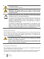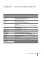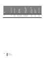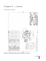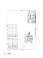
1
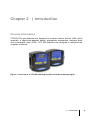
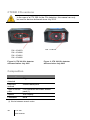
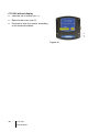
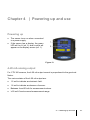
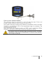
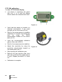
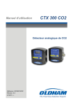
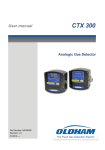
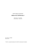
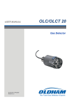
User manual CTX 300 CO2 Analogic CO2 Gas Detector Part Number: NP300CO2GB Revision: A.0 07/2015→ The Fixed Gas Detection Experts Copyright 2015 by Oldham S.A.S. July 2015 All rights reserved. No reproduction of all or part of this document, in any form, is permitted without the written consent of Oldham S.A.S. All information provided in this document is accurate to the best of our knowledge. As a result of continuous research and development, the specifications of this product may be changed without prior notice. Oldham S.A.S Rue Orfila Z.I. Est – CS 20417 F – 62027 ARRAS Cedex Tel : +33 (0)3 21 60 80 80 Fax: +33 (0)3 21 60 80 00 2 CTX 300 User manual Contents Chapter 1 | General Information ..............................................5 User Manual ............................................................................................... 5 Symbols used ............................................................................................. 5 Safety instructions ...................................................................................... 6 Important information ................................................................................. 6 Liability limits .............................................................................................. 7 Chapter 2 | Introduction ...........................................................9 General Information ................................................................................... 9 CTX300 CO2 versions .............................................................................. 10 Composition ............................................................................................. 10 Chapter 3 | Installation and connection ................................ 11 Installing the detectors ............................................................................. 11 Electrical connections .............................................................................. 13 Chapter 4 | Powering up and use .......................................... 17 Powering up ............................................................................................. 17 4-20 mA analog output ............................................................................. 17 Chapter 5 | Maintenance ........................................................ 18 Calibration ................................................................................................ 18 Checking the current generator................................................................ 23 Replacing a sensor .................................................................................. 24 Disposal.................................................................................................... 24 Chapter 6 | Spare parts .......................................................... 25 CTX 300 CO2 ........................................................................................... 25 Chapter 7 | Certification ......................................................... 27 Contents 3 Chapter 8 Technical specifications ....................................... 29 Chapter 9 | Annex ................................................................... 31 CTX 300 overview .................................................................................... 31 4 CTX 300 User manual | Chapter 1 | General Information User Manual The instructions given in this manual must be read thoroughly before installation and start-up, particularly those concerning the points related to the safety of the end-user. This user manual must be made available to every person involved in the activation, use, maintenance, and repair of the unit. The information, technical data, and diagrams contained in this manual are based on the information that is available at a given time. In case of doubt, contact Oldham for additional information. The aim of this manual is to supply simple and accurate information to the user. Oldham cannot be held liable for any misinterpretations in the reading of this manual. In spite of our efforts to produce an error-free manual, it may nonetheless contain some unintentional technical inaccuracies. In the client’s interest, Oldham reserves the right to modify the technical characteristics of its equipment to increase their performance without prior notice. The present instructions and their content are the inalienable property of Oldham. Symbols used Icon Significance This symbol indicates useful additional information. This symbol indicates: This equipment must be connected to ground. This symbol indicates: Protective earth terminal. A cable of the adequate diameter must be connected to ground and to the terminal having this symbol. 1 – General information 5 This symbol indicates: You must refer to the instructions. This symbol indicates: Warning! In the present mode of use, failure to adhere to the instructions preceded by this symbol can result in a risk of electric shock and/or death. European Union (and EEA) only. This symbol indicates that this product must not be discarded with household waste, as per the EEA directive (2002/96/EC) and your own national regulations. This product must be disposed of at a collection point that is reserved for this purpose, for example, an official site for the collection of electrical and electronic equipment (EEE) in view of their recycling, or a point of exchange for authorized products that is accessible when you acquire a new product of the same type. Any deviation as regards these recommendations for the disposal of this type of waste can have negative effects on the environment and public health, as these electric and electronic products generally contain substances that can be dangerous. Your full cooperation in the proper disposal of this product promotes a better use of natural resources. Safety instructions Labels intended to remind you of the principal precautions of use have been placed on the unit in the form of pictograms. These labels are considered an integral part of the unit. If a label falls off or becomes illegible, please ensure it is replaced. The significance of the labels is detailed below. The installation and electrical connections must be carried out by qualified personnel according to the instructions of the manufacturer and the standards of the competent authorities. Failure to adhere to the instructions can have serious consequences on the safety of persons. Please be extremely rigorous as regards electricity and assembly (coupling, network connections). Important information The modification of the material and the use of parts of an unspecified origin shall entail the cancellation of any form of warranty. The use of the unit has been projected for the applications specified in the technical characteristics. Exceeding the indicated values cannot in any case be authorized. 6 CTX 300 User manual Liability limits Neither Oldham nor any other associated company under any circumstances can be held liable for any damage, including, without limitations, damages for loss or interruption of manufacture, loss of information, defect of the MX 43 control unit, injuries, loss of time, financial or material loss, or any direct or indirect consequence of loss occurring in the context of the use or impossibility of use of the product, even in the event that Oldham has been informed of such damage. 1 – General information 7 8 CTX 300 User manual Chapter 2 | Introduction General Information CTX300 CO2 gas detectors are designed to measure carbon dioxide. With robust materials, a specifically-adapted design, appropriate accessories, stainless bolts and a polyamide case (IP54), CTX 300 detectors are designed to withstand the roughest conditions. Figure 1: overview of a CTX 300 with display (left) and without display (right). 2 - Introduction 9 CTX300 CO2 versions In the case of a CTX 300 for the CO2 detection, this manual can only be used for devices delivered since July 2015. P/N : 6314124 P/N : 6514879 P/N : 6514880 P/N : 6514881 P/N : 6514882 Figure 2: CTX 300 CO2 detector delivered before July 2015 Figure 3: CTX 300 CO2 detector delivered since July 2015 Composition Sensor type CTX 300 Gases detected CO2. Detection method Infrared absorption. Type of sensor pack Pre-calibrated removable sensor pack (1). Options With display. Certification None (1) Choice between several scales. 10 CTX 300 User manual Chapter 3 | Installation and connection Installing the detectors Layout While the measuring sensor is always located on the underside of the detector, several factors determine where the detector should be located: ■ If the gas being measured is lighter than the air, place the detector near the ceiling. ■ If the gas is heavier than the air (CO2 and Freons, for example) place the detector close to the floor. ■ Near offtake points. ■ Generally, in locations where gas may accumulate, taking into consideration both: - The effects of temperature; - The outside winds direction. Determining the best sensor location Factors to consider when determining the best placement for the detector are: ■ Potential sources for vapor and gas emissions. ■ Characteristics of gases and vapors (density). ■ Air circulation: - Inside: mechanical or natural ventilation. - Outside: wind direction and velocity. ■ Effects of temperature. ■ Local constraints (air flow, water splash, etc.). Detectors should always be located in an easily accessible location for maintenance purposes. Special accessories may be necessary to protect the equipment against any liquid projectiles, dust, direct sunlight or low temperatures in the area. 3 - Installation and connection 11 Mechanical installation Figure 4: overall dimensions of the CTX 300. Figure 5: drilling diagram for wall mounting (view of the side flatten onto the ceiling). 12 CTX 300 User manual Figure 6: ceiling mounting with a brace. The fixing drawing is identical to this of the wall mount. Ref. Qty Description Code Material 1 1 Brace 6132380 Stainless 2 4 Washer A25 ACCD 6905518 Stainless 3 4 Screw CHC LI2 6902218 Stainless Electrical connections Wiring specifications If needed, consult the grounding instructions for Oldham instruments and related connection materials in Annex 1. Connections for the various types of sensors Wire CTX 300 CO2 with display CTX 300 CO2 without display Output signal 4-20 mA 4-20 mA Active wires 3 3 Cable entry 1 x 6-11 mm 1 x 6-11 mm 3 - Installation and connection 13 Connection of a 3-wire sensor to an Oldham control unit Wire Terminal number (+) V DC power supply: 3 (-) V DC power supply (masse 0 V): 2 Output signal: 1 Control unit +24 VDC Detector 0V Signal Figure 7: connection of a 3-wire sensor to an Oldham control unit. Connection of a 3-wire CTX300 sensor to a non-OLDHAM control unit with an internal power supply Other control unit +24 VDC 0V Detector Signal Figure 8: Connection of a 3-wire CTX300 sensor to a non-OLDHAM control unit. (R) (A) 14 Maximal load = 200 Ω. Power supply 15 ≤ Vcc ≤ 32. 18 ≤ Vcc ≤ 30 for CO2 sensor. I max = 100 mA. CTX 300 User manual Operating mode CTX300 with display ■ Remove the 4 screws (ref. 1). ■ Remove the cover (ref. 2). Figure 9 ■ Completely remove the screw (ref. 4). ■ Unscrew the screw a few turns (ref. 3). Figure 10 ■ Turn the display circuit as shown (ref. 5). ■ Connect the cable (ref. 6) to the connector. Refer to paragraph Connections for the various types of sensors on page 13. ■ Return the display circuit to its original position and replace the cover. Figure 11 3 - Installation and connection 15 CTX 300 without display ■ Unscrew the 4 screws (ref. 1). ■ Remove the cover (rep. 2). ■ Proceed to wire the sensor according to the terminal location. Figure 12 16 CTX 300 User manual Chapter 4 | Powering up and use Powering up ■ The sensor turns on when connected to a power supply. ■ If the sensor has a display, the green LED will be lit (ref. 2) and a value will appear on the display screen (ref. 1). Figure 13 4-20 mA analog output For CTX 300 sensors, the 4-20 mA output current is proportional to the gas level. Notes: The various states of the 4-20 mA output are: ■ 1.5 mA to indicate an electronic fault. ■ 1.8 mA to indicate an absence of sensor. ■ Between 4 and 20 mA for measurement values. ■ ≥ 20 mA if levels exceed measurement range. 4 – Powering up and use 17 Chapter 5 | Maintenance The adjustment operations in this paragraph are reserved for authorized, trained personnel because they may compromise detection reliability . Gas detectors are safety devices. OLDHAM recommends the regular testing of fixed gas detection installations. This type of test consists of injecting the calibration gas into the detector at a sufficient concentration to activate the pre-set alarms. It is to be understood that this test is in no way a replacement for a detector calibration. The frequency of gas tests depends on the industrial application where the detector is in use. Frequent inspections should be made in the months following the commissioning of the installation, and should then become more widely spaced provided that no significant deviation is observed. If a detector should fail to react in contact with the gas, calibration is essential. The frequency of calibrations shall be appropriate according to the results of the tests (humidity, temperature, dust, etc.); however, it must not exceed one year. The general manager should put safety procedures in place on-site. OLDHAM cannot be held responsible for their enforcement. Calibration Recommendations Calibration consists of adjusting the zero of the clean air sensor and adjusting sensitivity with a test gas. Adjustments are made at the sensor level. Equipment needed to calibrate the detector correctly: ■ Flexible plastic tubing (Figure 14, ref. 2). ■ Manometer and regulator valve for the compressed gas cylinders (rep. 3). ■ 0 to 60 l/h flow meter (if the cylinder is not equipped with one). ■ Calibration pipe (ref. 1), which may vary depending on the nature of the gas (see pages 25 and following). ■ Test gas cylinder (ref. 4). 18 CTX 300 User manual Figure 14: sensor calibration assembly. Zero adjustment should be performed in a gas and vapor free area. If this is not possible, synthetic bottled air can be injected at a rate of 60 l/h. Use a bottle of test gas to adjust sensor sensitivity (concentration close to the alarm threshold or corresponding to 30% of the measurement range at a minimum). The recommended rate is 60 l/h. Note: when dealing with dangerous gases, you MUST consult a specialized Oldham technician or use another sensor pack recently pre-calibrated at a factory. The detector should be calibrated using the intended flow-rate. The actual concentration of gas may be underestimated if the detector was calibrated with too high of a flow rate. 5 – Maintenance 19 CTX 300 calibration st 1 case: CTX 300 with display ■ The sensor is operating: the green light (ref. 1) is lit and the display screen shows the measurement level. Figure 15 ■ Verify that the sensor is located in a clean-air environment. If not, inject synthetic air at a flow rate of 60 l/h. ■ Wait for the measurement to stabilize (displayed on screen) and adjust the zero by using the ZERO potentiometer located on the sensor pack (ref. 2). ■ Inject the recommended calibration gas at a flow rate of 60 l/h. ■ Wait for the measurement to stabilize. ■ Adjust the sensitivity by using the sensitivity potentiometer located on the sensor pack (rep. 1). ■ Stop injecting the calibration gas. ■ Remove the gas injection pipe, then wait and verify that the signal returns to zero. Repeat procedure if it does not. ■ Calibration is complete. 20 CTX 300 User manual Figure 16 2 nd case: CTX 300 without display ■ The sensor is operating. ■ Verify that the sensor is located in a clean-air environment. Use the calibration kit and follow all recommendations. ■ Connect a voltmeter to the AF+ and AF- terminals (caliber mV/DC). Figure 17 ■ Wait for the signal to stabilize and adjust the zero by using the ZERO potentiometer located on the sensor pack (Figure 18, ref. 2). The output signal should be 0 mV. ■ Now inject the recommended test gas at a flow rate of 60 l/h. Use the calibration kit and follow all recommendations. ■ Wait until the signal has stabilized. ■ Read the mV value on the voltmeter (Figure 17), with the full scale at 1600 mV. Calculate the value to be read as a function of your test gas. Figure 18 5 – Maintenance 21 ■ Adjust the displayed value using the potentiometer (Figure 18, rep.1). Example - CO2 sensor. - Scale 0-5000 ppm. - Standard gas concentration: 3000 ppm. - Reading: 1360 mV. ■ Shut off the calibration gas injection. ■ Withdraw the gas injection pipe. ■ Then wait and check that the scale has returned to zero. Otherwise, repeat the entire procedure. 22 CTX 300 User manual Checking the current generator Although this setting is made in the factory, it is possible that the transmitter and controller may have to be matched. In this case, proceed as follows: ■ Connect a voltmeter to the AF+ and AF- terminals (caliber mV/DC) (Figure 19). ■ Verify that the sensor is located in a clean-air environment. If not, inject synthetic air at a flow rate of 60 l/h. Figure 19 ■ 112 Wait for the measurement to stabilize (displayed on screen) and adjust the zero by using the ZERO potentiometer located on the sensor pack (Figure 20, ref. 2). ■ The instrument then sends a 4 mA signal down the line. Connect a voltmeter to the VI+ and VIterminals (caliber mV/DC). The multimeter displays 400 mV ■ If some different value is displayed, adjust P1 (Figure 21, rep. 1). ■ adjustment is complete. Figure 20 034 Figure 21 114 5 – Maintenance 23 Replacing a sensor Sensors must be replaced: ■ When calibration is no longer possible (no sensitivity); ■ During preventative maintenance. The replacement sensor should be identical to the original sensor (same gas, same range). After a sensor has been replaced, a calibration or test (for pre-calibrated sensors) must be conducted. Disposal For the preservation, protection and improvement of environmental quality, and for the protection of human health and the prudent and rational utilization of natural resources, the CTX 300 must be disposed of separately from electronic equipment and cannot be disposed of with normal household waste. The user therefore has an obligation to separate the CTX 300 sensor from other waste to ensure that it is recycled safely for the environment. For further details on existing collection sites, contact the local administration or seller of the product. 24 CTX 300 User manual Chapter 6 | Spare parts List of spare parts for different detectors. Replacement parts must imperatively be guaranteed origin Oldham. Otherwise, material safety could be jeopardized. CTX 300 CO2 P/N Description 6147868 CTX 300 tool kit. 6322420 Mounting brace and bolts (CTX 300) ceiling mount. 6323607 Gas collector (s). 6331137 Gas introduction device for O2, C0, H2S, NO, H2. 6331141 Gas introduction device for explosible gases and other toxic gases. Picture 6 – Spare parts 25 P/N Description 6327906 Device for remote gas introduction. 6335953 Replacement filter. PTFE protector filter. Pre-calibrated CO2 sensor pack 6314193 CTX 300 CO2 - 5000 ppm / 0.50% vol. sensor pack. 6314191 CTX 300 CO2 – 5% vol. sensor pack. 6314192 CTX 300 CO2 – 100% vol. sensor pack. Replacement parts 6323608 Cover without display. 6323609 Cover with display. 6815919 CTX 300 without display label. 6815921 CTX 300 wit display label. 6451466 Display card. 6815923 Localization sticker. 6451644 Motherboard. 26 CTX 300 User manual Picture Chapter 7 | Certification The following page reproduces the EC declaration of conformity. 7 - Certification 27 28 CTX 300 User manual Chapter 8 Technical specifications Enclosure. Polycarbonate housing. Function. Detector-transmitter Highly visible backlight display unit (optional, gas dependent) In operation: green color (on CTX 300 : 3-wire) Failure / maintenance: yellow color 2 wires, shielded LiYCY type – CTX 300 without display unit 3 wires, shielded LiYCY type – CTX 300 with display unit PG9 cable gland (outer diameter 6 to 11 mm) Display Indicator lights Link Cable entry Power consumption Operating temperature 15 to 32 V DC CTX 300 without display unit: 60 mA CTX 300 with display unit: 100 mA -20°C to +50°C, -4 to + 122°F with display -40°C to + 50°C, -40°F to + 122°F without display Sealing IP 54, NEMA 3 & 3R Weight 520 g Dimensions 130 x 136 x 69 (l x h x d) in mm ; (5.12" x 5.35" x 2.72") Type 1 & 2 according to EN 50270:06 32 ohms max loop for CTX 300 with display unit 64 ohms max loop for CTX 300 without display unit Power supply EMC Impedance 8 – Technical specifications 29 IR : Infrared 30 CTX 300 User manual Accuracy (at PA full scale) Life span (in month) T(50) (seconds) -40°C to +50°C -40°C to +50°C -40°C to +50°C Relative humidity uncondensed 0.50% 5.00% 100% Operating temperature Type of sensor IR Range (ppm) Gas CO2 0% to 95% RH 0% to 95% RH 0% to 95% RH +/-2% +/-2% +/-2% 60 60 60 <20 <20 <20 Chapter 9 | Annex CTX 300 overview Figure 22: CTX 300 with sensor pack and display – overview. 9 – Annex 31 Figure 23: CTX 300 – overview. 32 CTX 300 User manual 9 – Annex 33 34 CTX 300 User manual 9 – Annex 35 The Fixed Gas Detection Experts EUROPEAN PLANT AND OFFICES Z.I. Est – rue Orfila CS 20417 – 62027 Arras Cedex FRANCE Tél: +33 (0)3 21 60 80 80 – Fax: +33 (0)3 21 60 80 00 Website: http://www.oldhamgas.com AMERICAS Tel: +1 713-559-9280 Fax: +1 281-292-2860 [email protected] ASIA PACIFIC Tel: +86-21-3127-6373 Fax: +86-21-3127-6365 [email protected] EUROPE Tel: +33-321-608-080 Fax: +33-321-608-000 [email protected]