1
Installation Guide
Release 3.5
June 2010
Release 3.5
June 2010
Vertical Communications, Inc. reserves the right to revise this publication and to make
changes in content without notice.
© 2010 by Vertical Communications, Inc. All rights reserved.
This publication contains proprietary and confidential information of Vertical Communications, Inc. The contents of this document may not be disclosed, copied or translated by third
parties, in any form, or by any means known, or not now known or conceived, without prior
explicit written permission from Vertical Communications, Inc.
LIMIT OF LIABILITY/DISCLAIMER OF WARRANTY
Vertical Communications, Inc. makes no representation or warranties with respect to the
accuracy or completeness of the content of this publication and specifically disclaims any
implied warranty of merchantability or fitness for any particular purpose, and shall not be
liable for any loss of profit or any other commercial damage, including but not limited to,
special, incidental, or consequential.
TRADEMARKS
Vertical Communications and the Vertical Communications logo and combinations thereof
are trademarks of Vertical Communications, Inc. All other brand and product names are
used for identification only and are the property of their respective holders.
RESTRICTED RIGHTS LEGEND
Use, duplication, or disclosure of the technical data contained in this document by the Government is subject to restrictions as set forth in subdivision (c) (1) (ii) of the Rights in Technical Data and Computer Software clause at DFARS 52.227-7013 and/or in similar or
successor clauses in the FAR, or in the DOD or NASA FAR Supplement. Unpublished
rights reserved under the Copyright Laws of the United States. Contractor/manufacturer is
Vertical Communications, Inc., 10 Canal Park, Suite 602, Cambridge, MA 02141-2249.
Release 3.5
June 2010
REVISION HISTORY
Release
Date
3.5
06-10
Documentation Changes
Update -- EKSU (p/n 4002-03) now shows 16-port capability.
Update -- dial pad graphic has been modified.
3.0
2.1
09-08
2.0
07-08
1.0
Release 3.5
11-09
01-08
Release 3.0 added the following new hardware:
Page No.
2-4 and 4-9
6-14
--
MBU (p/n 4000-03) to accommodate 3.0 boards.
4-2
EMBU (p/n 4002-03) to accommodate 3x16 Expansion board
4-8
3x16 Expansion board (p/n 4032-16)
4-14
T1/PRI board (p/n 4035-00)
4-16
Updated the Voicemail specifications with recording times.
4-21
A section has been added that addresses "Loading a 2.5
database onto a 3.0 system".
7-8
Added a System Upgrade Configuration procedure.
7-10
Added a T1/PRI Firmware Upgrade procedure.
8-16
Formatting & editing have been done to certain sections for
greater ease of understanding. No features have been added or
removed.
--
25-pair cable pin outs have been added (p/n 4099-00).
4-7
A VoIB software upgrade procedure (web-based) has been
added.
8-13
Added information on KSU administration via RJ-45 LAN port by
direct connection and by connection to the KSU over a LAN
switch.
9-17
A "BLF Manager" section has been added.
6-16
A section has been added that addresses uploading new VMIB
prompts.
8-9
A system setup quick reference Appendix has been added.
Appendix A
A section has been added that addresses IP Phones on the
SBX IP.
5-22
Initial Release
NOTE: this document contains information on ISDN, DCOB, and
SMS. These features are currently not supported.
Information pertaining to DID pertains only to SIP Trunking.
--
June 2010
Contents
Chapter 1
Introduction
Important Safety Instructions - - - - - - - - - - - - - - - - - - - - - - - - Safety Requirements - - - - - - - - - - - - - - - - - - - - - - - - - - - Precautions - - - - - - - - - - - - - - - - - - - - - - - - - - - - - - - - - Cautions - - - - - - - - - - - - - - - - - - - - - - - - - - - - - - - - - - - Disposal of Old Units - - - - - - - - - - - - - - - - - - - - - - - - - - - Using this Manual - - - - - - - - - - - - - - - - - - - - - - - - - - - - - - - - -
Chapter 2
System Overview
SBX IP System Highlights - - - - - - - - - - - - - - - - - - - - - - - - - - Supported phones - - - - - - - - - - - - - - - - - - - - - - - - - - - - - System Connection Diagram - - - - - - - - - - - - - - - - - - - - - - - - System Components - - - - - - - - - - - - - - - - - - - - - - - - - - - - - Basic KSU (p/n 4000-00) - - - - - - - - - - - - - - - - - - - - - - - - Expansion KSU (p/n 4002-00) - - - - - - - - - - - - - - - - - - - - KSU (p/n 4000-03) for 3.0 s/w or higher - - - - - - - - - - - - - EKSU (p/n 4002-03) for 3.0 s/w or higher - - - - - - - - - - - - System Specification Tables - - - - - - - - - - - - - - - - - - - - - - - - Board Capacities - - - - - - - - - - - - - - - - - - - - - - - - - - - - - System Capacities - - - - - - - - - - - - - - - - - - - - - - - - - - - - Dialing Specifications - - - - - - - - - - - - - - - - - - - - - - - - - - Dimensions and Weight - - - - - - - - - - - - - - - - - - - - - - - - - Environmental Specifications - - - - - - - - - - - - - - - - - - - - - Electrical Specifications - - - - - - - - - - - - - - - - - - - - - - - - - -
Chapter 3
1-1
1-1
1-2
1-2
1-3
1-4
2-1
2-1
2-2
2-3
2-3
2-3
2-4
2-4
2-5
2-5
2-6
2-7
2-7
2-7
2-8
KSU Installation
Pre-Installation - - - - - - - - - - - - - - - - - - - - - - - - - - - - - - - - - - - 3-1
Safety Installation Instructions - - - - - - - - - - - - - - - - - - - - - 3-1
Installation Precautions - - - - - - - - - - - - - - - - - - - - - - - - - - 3-2
Release 3.5
SBX IP Installation Guide
June 2010
Contents
TOC-2
Wiring Precautions - - - - - - - - - - - - - - - - - - - - - - - - - - - - - - 3-2
KSU Installation - - - - - - - - - - - - - - - - - - - - - - - - - - - - - - - - - - - 3-3
Unpacking - - - - - - - - - - - - - - - - - - - - - - - - - - - - - - - - - - - - 3-3
KSU Exterior and Dimension - - - - - - - - - - - - - - - - - - - - - - - 3-4
Opening and Closing the Front Cover - - - - - - - - - - - - - - - - 3-5
Frame Ground Connection - - - - - - - - - - - - - - - - - - - - - - - - 3-7
External Backup Battery Installation - - - - - - - - - - - - - - - - - - 3-8
KSU Mounting - - - - - - - - - - - - - - - - - - - - - - - - - - - - - - - - - 3-9
Expansion KSU Installation - - - - - - - - - - - - - - - - - - - - - - - - - - 3-12
Unpacking - - - - - - - - - - - - - - - - - - - - - - - - - - - - - - - - - - - 3-12
Connecting the Expansion KSU to the Basic KSU - - - - - - - 3-13
Expansion KSU Mounting - - - - - - - - - - - - - - - - - - - - - - - - 3-15
Chapter 4
Board Installation
Basic Board Installations - - - - - - - - - - - - - - - - - - - - - - - - - - - - 4-2
Main Board Unit (p/n: 4000-00) - - - - - - - - - - - - - - - - - - - - - 4-2
Main Board Unit (p/n: 4000-03) - - - - - - - - - - - - - - - - - - - - - 4-2
Modular Jack (MJ1 - MJ3) Pin Assignment - - - - - - - - - - - - - 4-4
Switch, LED, and Connector - - - - - - - - - - - - - - - - - - - - - - - 4-6
SBX 25-Pair Installation Cable Pinouts - - - - - - - - - - - - - - - - 4-7
Expansion Main Board Unit (EMBU) - - - - - - - - - - - - - - - - - - - - 4-8
Expansion MBU (p/n: 4002-00) - - - - - - - - - - - - - - - - - - - - - 4-8
Expansion MBU (p/n: 4002-03) - - - - - - - - - - - - - - - - - - - - - 4-8
Modular Jack (MJ1 - MJ3) Pin Assignment - - - - - - - - - - - - 4-10
CO Line and Extension Boards - - - - - - - - - - - - - - - - - - - - - - - 4-12
3x8 Expansion Board (3 CO Line and 8 Hybrid) - - - - - - - - 4-12
3x16 Expansion Board (3 CO Line and 16 Digital) - - - - - - - 4-13
Other Board Installations (optional) - - - - - - - - - - - - - - - - - - - - 4-14
Digital Telephone Interface Board (DTIB16) - - - - - - - - - - - 4-14
Modem Function Unit (MODU) - - - - - - - - - - - - - - - - - - - - 4-15
T1/PRI Interface Board - - - - - - - - - - - - - - - - - - - - - - - - - - 4-16
VoIB -- Voice Over Internet Protocol Board (4ch) - - - - - - - 4-18
Voice Mail Interface Board (VMIB) - - - - - - - - - - - - - - - - - - 4-21
Release 3.5
SBX IP Installation Guide
June 2010
Contents
Chapter 5
TOC-3
Terminal Connection and Wiring Method
Terminal and Doorbox Models - - - - - - - - - - - - - - - - - - - - - - - - 5-1
Terminal Cabling Distance - - - - - - - - - - - - - - - - - - - - - - - - - - 5-3
Basic Terminal Connection - - - - - - - - - - - - - - - - - - - - - - - - - - 5-4
DKT and DSS - - - - - - - - - - - - - - - - - - - - - - - - - - - - - - - - - 5-4
SLT - - - - - - - - - - - - - - - - - - - - - - - - - - - - - - - - - - - - - - - - 5-4
Doorbox - - - - - - - - - - - - - - - - - - - - - - - - - - - - - - - - - - - - - 5-5
Connecting Additional Terminals - - - - - - - - - - - - - - - - - - - - - - 5-7
External Music Source Wiring - - - - - - - - - - - - - - - - - - - - - 5-8
Relay Contacts - - - - - - - - - - - - - - - - - - - - - - - - - - - - - - - - 5-8
External Paging Port Wiring - - - - - - - - - - - - - - - - - - - - - - - 5-8
Alarm Detection Wiring - - - - - - - - - - - - - - - - - - - - - - - - - - 5-8
Cable Wiring - - - - - - - - - - - - - - - - - - - - - - - - - - - - - - - - - - - - 5-9
Wall Mount Wiring - - - - - - - - - - - - - - - - - - - - - - - - - - - - - - 5-9
Rack Mount Wiring - - - - - - - - - - - - - - - - - - - - - - - - - - - - 5-10
IP Phones on the SBX IP - - - - - - - - - - - - - - - - - - - - - - - - - - 5-11
Supported IP phones: - - - - - - - - - - - - - - - - - - - - - - - - - - 5-11
Minimum requirements - - - - - - - - - - - - - - - - - - - - - - - - - 5-11
IP endpoint licensing - - - - - - - - - - - - - - - - - - - - - - - - - - - 5-12
IP Addressing - - - - - - - - - - - - - - - - - - - - - - - - - - - - - - - - 5-12
Preparation - - - - - - - - - - - - - - - - - - - - - - - - - - - - - - - - - 5-14
PCAdmin Connection - - - - - - - - - - - - - - - - - - - - - - - - - - 5-14
Configuring IP phone settings - - - - - - - - - - - - - - - - - - - - 5-20
Programming VoIP card settings from a digital station - - - 5-22
Chapter 6
Starting the SBX IP System
Before Starting the SBX IP System - - - - - - - - - - - - - - - - - - - - 6-1
Basic Programming - - - - - - - - - - - - - - - - - - - - - - - - - - - - - - - 6-2
DKT Programming - - - - - - - - - - - - - - - - - - - - - - - - - - - - - 6-2
Entering the Programming Mode - - - - - - - - - - - - - - - - - - - 6-5
Pre-Programming - - - - - - - - - - - - - - - - - - - - - - - - - - - - - - 6-6
BLF Manager - - - - - - - - - - - - - - - - - - - - - - - - - - - - - - - - - - - 6-16
BLF Manager Installation - - - - - - - - - - - - - - - - - - - - - - - - 6-16
BLF Manager in detail - - - - - - - - - - - - - - - - - - - - - - - - - - 6-17
Release 3.5
SBX IP Installation Guide
June 2010
Contents
TOC-4
System list window (Status of systems) - - - - - - - - - - - - - Station list window (Extension status) - - - - - - - - - - - - - - - Network traffic window - - - - - - - - - - - - - - - - - - - - - - - - - File menu - - - - - - - - - - - - - - - - - - - - - - - - - - - - - - - - - - -
Chapter 7
6-17
6-18
6-18
6-18
Using Database Upload/Download
PC Requirement - - - - - - - - - - - - - - - - - - - - - - - - - - - - - - - 7-1
Connection Method with SBX IP - - - - - - - - - - - - - - - - - - - - 7-1
Installation - - - - - - - - - - - - - - - - - - - - - - - - - - - - - - - - - - - - - - 7-2
Main software components - - - - - - - - - - - - - - - - - - - - - - - - 7-2
Choosing Up/Download and Connection Type - - - - - - - - - - 7-2
User Information Dialog - - - - - - - - - - - - - - - - - - - - - - - - - - 7-3
Starting Database File Upload/Download - - - - - - - - - - - - - - - - - 7-6
Transferring Process - - - - - - - - - - - - - - - - - - - - - - - - - - - - 7-7
Finishing DataBase File Upload/Download - - - - - - - - - - - - - 7-7
Loading a 2.5 Database into a 3.0 System - - - - - - - - - - - - - - - - 7-8
Loading the Database - - - - - - - - - - - - - - - - - - - - - - - - - - - - 7-8
Example -- System Upgrade Configuration - - - - - - - - - - - - 7-10
Chapter 8
Upgrade Process
Software Upgrade - - - - - - - - - - - - - - - - - - - - - - - - - - - - - - - - - 8-1
Minimum PC Requirement - - - - - - - - - - - - - - - - - - - - - - - - 8-1
Connection Method with SBX IP - - - - - - - - - - - - - - - - - - - - 8-1
Installation - - - - - - - - - - - - - - - - - - - - - - - - - - - - - - - - - - - - - - 8-2
File Component in the Execution Directory - - - - - - - - - - - - - 8-2
Choosing Up/Download and Connection Type - - - - - - - - - - 8-2
User Information Dialog - - - - - - - - - - - - - - - - - - - - - - - - - - 8-3
Starting Software Upgrade - - - - - - - - - - - - - - - - - - - - - - - - - - - 8-6
Transferring Process - - - - - - - - - - - - - - - - - - - - - - - - - - - - 8-7
Completing Software Upload - - - - - - - - - - - - - - - - - - - - - - - 8-7
Uploading new VMIB prompts - - - - - - - - - - - - - - - - - - - - - - - - - 8-9
Prerequisites: - - - - - - - - - - - - - - - - - - - - - - - - - - - - - - - - - - 8-9
Upgrading Voice Prompts - - - - - - - - - - - - - - - - - - - - - - - - - 8-9
VoIB Software Upgrade by Web-based Connection - - - - - - - - 8-13
T1/PRI Firmware Upgrade - - - - - - - - - - - - - - - - - - - - - - - - - - 8-16
Release 3.5
SBX IP Installation Guide
June 2010
Contents
TOC-5
Verify network settings - - - - - - - - - - - - - - - - - - - - - - - - - 8-16
Downloading firmware file - - - - - - - - - - - - - - - - - - - - - - - 8-16
Chapter 9
Remote Diagnostics
Introduction - - - - - - - - - - - - - - - - - - - - - - - - - - - - - - - - - - - - - 9-1
Hardware/Software Minimum Requirements - - - - - - - - - - - 9-1
Hardware Configuration - - - - - - - - - - - - - - - - - - - - - - - - - - 9-2
Installing Software - - - - - - - - - - - - - - - - - - - - - - - - - - - - - - 9-2
Uninstalling Software - - - - - - - - - - - - - - - - - - - - - - - - - - - - 9-3
Important Notes for Users - - - - - - - - - - - - - - - - - - - - - - - - 9-3
Full Screen Layout - - - - - - - - - - - - - - - - - - - - - - - - - - - - - 9-4
File Menu - - - - - - - - - - - - - - - - - - - - - - - - - - - - - - - - - - - - - - 9-4
Open Sub-menu - - - - - - - - - - - - - - - - - - - - - - - - - - - - - - - 9-5
Capture On Sub-menu - - - - - - - - - - - - - - - - - - - - - - - - - - 9-5
Capture Off Sub-menu - - - - - - - - - - - - - - - - - - - - - - - - - - 9-5
Connection Menu - - - - - - - - - - - - - - - - - - - - - - - - - - - - - - - - - 9-6
Serial Port Connection with SBX IP System - - - - - - - - - - - - 9-6
Modem Connection with the SBX IP System - - - - - - - - - - - 9-9
LAN Connection with the SBX IP System - - - - - - - - - - - - 9-17
Commands Menu - - - - - - - - - - - - - - - - - - - - - - - - - - - - - - - - 9-28
Executing Commands - - - - - - - - - - - - - - - - - - - - - - - - - - 9-29
Functions of Commands - - - - - - - - - - - - - - - - - - - - - - - - 9-31
View Menu - - - - - - - - - - - - - - - - - - - - - - - - - - - - - - - - - - - - 9-46
Toolbar Sub-menu - - - - - - - - - - - - - - - - - - - - - - - - - - - - 9-46
Command Bar Sub-menu - - - - - - - - - - - - - - - - - - - - - - - 9-47
Input Box Bar Sub-menu - - - - - - - - - - - - - - - - - - - - - - - - 9-47
Clear New Sub-Menu - - - - - - - - - - - - - - - - - - - - - - - - - - 9-47
Help Menu - - - - - - - - - - - - - - - - - - - - - - - - - - - - - - - - - - - - - 9-48
About SBX Remote Diagnostic Tool Sub-menu - - - - - - - - 9-48
Data Display Area - - - - - - - - - - - - - - - - - - - - - - - - - - - - - - - 9-49
Data Display Functions - - - - - - - - - - - - - - - - - - - - - - - - - 9-49
Automatic Data Storing Functions - - - - - - - - - - - - - - - - - - 9-50
VoIB Maintenance - - - - - - - - - - - - - - - - - - - - - - - - - - - - - - - 9-51
Release 3.5
SBX IP Installation Guide
June 2010
Contents
Chapter 10
TOC-6
Troubleshooting
Symptons and Solutions - - - - - - - - - - - - - - - - - - - - - - - - - - - - 10-1
Appendix A
System Setup Quick Reference
Quick Start - - - - - - - - - - - - - - - - - - - - - - - - - - - - - - - - - - - - To initialize the system database: - - - - - - - - - - - - - - - - - To set the KSU admin password: - - - - - - - - - - - - - - - - - - To set the KSU LAN port IP address: - - - - - - - - - - - - - - - Default passwords - - - - - - - - - - - - - - - - - - - - - - - - - - - - RS-232 port settings - - - - - - - - - - - - - - - - - - - - - - - - - - - Default IP address - - - - - - - - - - - - - - - - - - - - - - - - - - - - -
A-1
A-1
A-1
A-1
A-2
A-2
A-2
Index
Release 3.5
SBX IP Installation Guide
June 2010
Chapter 1
Introduction
Important Safety Instructions
Safety Requirements
When using the telephone equipment, basic safety precautions should always be
followed to reduce the risk of fire, electric shock, and other personal injury. Please take
the following precautions:
•
•
•
•
•
•
•
•
•
•
•
•
Release 3.5
Read and understand all instructions.
Follow all warnings and instructions as marked on the product.
Unplug this product from the wall outlet before cleaning. A damp cloth should be
used for cleaning. Do not use liquid or aerosol cleaners.
Do not use this product near water: such as in a bathtub, sink, or swimming pool.
Do not place this product on an unstable stand or table. If the product falls, serious
damage can result.
Do not place this product on a bed, sofa, or other soft surface. Doing so may
prevent proper ventilation for the slots in the back or bottom of the KSU (key
system unit), causing the product to overheat. Do not place this product near or
over a radiator or other heat source. Do not use this product for in a built-in
installation without proper ventilation.
Use this product only with the type of power source indicated on the product label.
If you are not sure of the type of power supply appropriate for the intended
location, consult your dealer or local power company.
Do not allow anything to rest on the power cord. Do not place this product in an
area in which might step or trip on the cord.
Do not overload wall outlets and extension cords. This may result in fire or electric
shock.
Never push objects of any kind into this product through the slots or connectors.
This risks damage to the product, as well as fire and electric shock.
Never pour or spill liquid of any kind on the product.
To reduce the risk of electric shock, do not disassemble this product. Instead, take
it to a qualified person when service or repair work is required. Opening or
removing covers may expose you to dangerous voltages or other risk. Incorrect
reassembly can cause electric shock when the appliance is subsequently used.
SBX IP Installation Guide
June 2010
1-2
Chapter 1: Introduction
Important Safety Instructions
•
Unplug this product and refer servicing to qualified service personnel if/when:
•
the power supply cord or plug is damaged or frayed.
•
liquid has been spilled onto the product.
•
the product does not operate normally by following the operating instructions.
NOTE:
•
•
Adjust only those controls that are covered by the operating
instructions. Improper adjustment of other controls may result in
damage that can require extensive repair work by a qualified
technician.
•
the product has been dropped or the KSU has been damaged.
•
the product exhibits a distinct change in performance.
Avoid using a telephone during an electrical storm, as there may be a remote risk
of electric shock from lightning.
In the event of a gas leak, do not use the telephone near the leak.
Precautions
•
•
•
•
Keep the system away from heating appliances and electrical noise-generating
devices such as fluorescent lamps, motors and televisions. These noise sources
can interfere with the performance of the SBX IP system.
This system should be kept free of dust and moisture, and should not be exposed
to high temperature, vibration, or direct sunlight.
Do not attempt to insert wires or pins into the system. If the system does not
operate properly, the equipment should be repaired by an authorized service
center.
Do not use benzene, paint thinner, or an abrasive powder to clean the KSU. Clean
it by wiping with a soft cloth.
Cautions
•
•
•
This system should be installed and serviced by qualified service personnel only.
When a failure occurs which exposes any internal parts, disconnect the power
supply cord immediately, and return the system to the dealer.
To protect the PCB from static electricity, discharge body static before touching
connectors and/or components by touching the ground or wearing a ground strap.
Warning: There is a danger of explosion if the battery is incorrectly replaced. Replace
it only with the same or equivalent type recommended by the manufacturer. Dispose of
used batteries according to the manufacturer’s instructions.
Release 3.5
SBX IP Installation Guide
June 2010
1-3
Chapter 1: Introduction
Important Safety Instructions
Disposal of Old Units
The symbol below designates a product covered by the European Directive
2002/96/EC.
•
•
•
Release 3.5
All electric and electronic products must be disposed of in
special collection facilities appointed by government or
local/municipal authorities.
The correct disposal of the old appliances will help prevent
potential negative consequences for the environment as well
as human health.
For more detailed information about disposal of the old
appliances, please contact the waste disposal service in your
area, or the place of product purchase.
SBX IP Installation Guide
June 2010
1-4
Chapter 1: Introduction
Using this Manual
Using this Manual
This document provides general information covering the hardware description and
installation of the SBX IP system. While every effort has been taken to ensure the
accuracy of this information, Vertical Communications, Inc. makes no warranty of
accuracy or interpretations thereof.
Chapter 2 - System Overview
General information on the SBX IP system, including system specifications and
capacity.
Chapter 3 - KSU Installation
Detailed instructions for planning the installation site, and procedures to install the SBX
IP system.
Chapter 4 - Board Installation
Detailed instructions for installing components of the SBX IP board.
Chapter 5 - Terminal Connection and Wiring Method
Description of the kinds of terminals (including maximum distance) and other device
connections for each terminal.
Chapter 6 - Starting the SBX IP System
Instructions for starting the system, and instructions for basic admin programming.
Chapter 7 - Using Database Upload/Download
Procedures for the upload/download of SBX IP MBU Database from/to a PC file
Chapter 8 - Upgrade Process
Procedures for upgrading the KSU software.
Chapter 9 - Remote Diagnostics
Procedures for diagnosing system problems and performing system maintenance from
a remote site.
Chapter 10 - Troubleshooting
Information on troubleshooting common issues on the SBX IP system.
Release 3.5
SBX IP Installation Guide
June 2010
Chapter 2
System Overview
SBX IP System Highlights
Features of the SBX IP system include:
•
•
•
•
•
•
Flexible architecture
Simplified system structure
Powerful PC application via LAN, Modem, RS-232C (serial port)
Stable and enhanced voice features
Simple installation and efficient system management:
•
Remote admin and software upgrade through LAN connection
•
Remote admin and software upgrade through PSTN modem
Value-added features
•
Distinctive voice mail (ADPCM 32 Kbps)
•
Basic CID (CO and SLT) function
•
8 Poly internal MOH (13 music sources)
Supported phones
MODEL
Release 3.5
DESCRIPTION
7208D
8-button digital telephone
7224D
24-button digital telephone
IP7008D
8-button IP telephone
IP7024D
24-button IP telephone
IP7024LD
24-button IP telephone (large display)
Nomad IP
Wireless IP telephone
Nomad SP
Soft Phone
SBX IP Installation Guide
June 2010
2-2
Chapter 2: System Overview
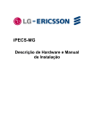
System Connection Diagram
System Connection Diagram
The following diagram shows the components that make up the SBX IP system:
SBX IP
Release 3.5
SBX IP Installation Guide
June 2010
2-3
Chapter 2: System Overview
System Components
System Components
Basic KSU (p/n 4000-00)
ITEM
BKSU
DESCRIPTION
Power Supply Unit (PSU)
Main Board Unit (MBU)
3x8 Expansion Board (3 CO, 1 DKT, and 7 Hybrid)
OPTIONAL BOARDS:
3x8 Expansion Board
3 CO, 1 DKT, and 7 Hybrid
MODU
Analog Modem -- Bell, ITU-T, V.34 V.32BIS, V.90
VMIB
Voice Mail Interface Board, 4 channels
VoIB
LAN Interface Board
NOT SUPPORTED
EKSU (p/n 4002-03)
T1/PRI Board
DTIB16 Board
Expansion KSU (p/n 4002-00)
ITEM
EKSU
DESCRIPTION
Power Supply Unit (PSU)
Expansion Main Board Unit (EMBU)
3x8 Expansion Board (3 CO, 1 DKT, and 7 Hybrid)
OPTIONAL BOARDS:
3x8 Expansion Board
NOT SUPPORTED
Release 3.5
3 CO, 1 DKT, and 7 Hybrid
KSU (p/n 4000-03)
3x16 Expansion Board
SBX IP Installation Guide
June 2010
2-4
Chapter 2: System Overview
System Components
KSU (p/n 4000-03) for 3.0 s/w or higher
ITEM
BKSU
DESCRIPTION
Power Supply Unit (PSU)
Main Board Unit (MBU)
OPTIONAL BOARDS:
3x8 Expansion Board
CO Line and DKT/SLT Interface Board
MODU
Analog Modem -- Bell, ITU-T, V.34 V.32BIS, V.90
T1/PRI
Digital trunk interface and 8 hybrid stations
VMIB
Voice Mail Interface Board, 4 channels
VoIB
LAN Interface Board
NOT SUPPORTED
EKSU (p/n 4002-00)
EKSU (p/n 4002-03) for 3.0 s/w or higher
ITEM
EKSU
DESCRIPTION
Power Supply Unit (PSU)
Expansion Main Board Unit (EMBU)
3x16 Expansion Board (3 CO, 16 DKT)
OPTIONAL BOARDS:
3x8 Expansion Board
3 CO, 1 DKT, and 7 Hybrid
3x16 Expansion Board 3 CO, 16 Digital ports
NOT SUPPORTED
Release 3.5
KSU (p/n 4000-00)
SBX IP Installation Guide
June 2010
2-5
Chapter 2: System Overview
System Specification Tables
System Specification Tables
Board Capacities
DESCRIPTION
Release 3.5
CAPACITY
BOARD
Alarm Input
1
MBU
CO Line Ports
4 (Total 12)
3x8 Expansion
DTMF/CPT Receiver Channels
16 chs
MBU
External MOH
1
MBU
External Paging Port
1
MBU
External Relay Contact
4
MBU (2), EMBU (2)
FSK Receiver Channels
16 chs
MBU
Internal MOH (13 Music Sources)
1
MBU
LAN
3
MBU, VoIB, E1HB8
Max Direct Station Connections
(DKT/SLT/DSS)
4 (Total 32)
3x8 Expansion
MODEM Channel
1
MODU
MODU
1
Modem Unit
Analog Modem
Bell, ITU-T, V.34 V.32BIS, V.90
Speed
300bps up to 33Kbps speed rate
Connection
Automatic rate negotiation
Power Fail Circuits
3
MBU (1), EMBU (1), 3x8 Expansion (1)
RS-232C Port
1
MBU
VoIB
1
Voice over Internet Board
LAN Interface
10 Base-T Ethernet (IEEE 802.3)
Speed
10/100 auto-negotiation, 100 Mbps
recommended
Duplex
Half or Full Duplex (Auto-Negotiation)
VoIP Protocol
H.323 Revision 4
Voice Compression
-- G.711/G.726/G729/G.723.1
Echo Cancellation
-- G.165
SBX IP Installation Guide
June 2010
2-6
Chapter 2: System Overview
System Specification Tables
System Capacities
ITEM
SPECIFICATION
Attendant Positions
5 - Main
1 - System
--
Authorization Codes
200
3-11 digits each
CO Line Groups
24
--
Conference
3-15 Parties
All ports are available
3-15 Parties
Max. 3 groups
Hunt Groups
10 groups
(620-629) 26 stations per group
Intercom Links
Non-Blocking
--
Last Number Redial
15-50
32 digits, via admin programming
Memory Back-up Duration
10 years
--
Paging Zones
- All Call
- External
- Internal
1
1
10
(549)
(545)
(501-510)
Station Groups
10
--
Station Speed Dial
100
(000-099) 24 digits each
System Speed Dial
500
(2000-2499) 24 digits each
Time Slots
128
--
Multi-line Conference
Release 3.5
CAPACITY
SBX IP Installation Guide
June 2010
2-7
Chapter 2: System Overview
System Specification Tables
Dialing Specifications
ITEM
DTMF Dialing
Pulse Dialing
DESCRIPTION
SPECIFICATION
Frequency Deviation
Less than +/-1.8%
Signal Rise Time
5 ms
Tone Duration, on time
Min. 50 ms, Normally 100 ms
Inter-digit Time
Min. 30 ms, Normally 100 ms
Pulse Rate
10 PPS
Break/Make Ratio
60/40% or 66/33%
Ring Detect Sensitivity --
30Vrms @ 16-55Hz
Ring Signal
--
75Vrms, 25Hz
Switching Device
--
Custom Mixed-Signal ASIC Device
Dimensions and Weight
ITEM
HEIGHT
WIDTH
(mm / in)
DEPTH
WEIGHT
(kg / lbs)
KSU / EKSU Cabinet
288 / 11.34
339 / 13.35
85 / 3.35
1.80 / 3.9
IP Keyset (IP7008D)
114 / 4.49
202 / 7.95
175 / 6.89
0.73 / 1.6
IP Keyset (IP7024D)
124 / 4.88
268 / 10.55
203 / 7.99
0.95 / 2.1
IP Keyset (IP7024LD)
147 / 5.79
268 / 10.55
243 / 9.57
1.03 / 2.3
Environmental Specifications
ITEM
Operating
Environment
Release 3.5
DESCRIPTION
SPECIFICATION
Temperature
0 (oC) – 40 (oC)
Humidity
0 - 80% (non-condensing)
SBX IP Installation Guide
June 2010
2-8
Chapter 2: System Overview
System Specification Tables
Electrical Specifications
ITEM
BatteryBackup (External)
Release 3.5
DESCRIPTION
SPECIFICATION
Input Voltage
+24 Volt DC (+12VDC x 2ea)
Battery Fuse
5.0A @250Volt AC
Charging Current
Max. 200mA
Battery Load Current
Max. 3A (BKSU only),
Max. 6A (BKSU + EKSU)
CPU
--
ARM7 TDMI core (32bit, 50MHz)
External Paging Port
--
0dBm @ 600ohm
External Relay Contact
--
1A @ 30Volt DC
Music Source Input
--
0dBm @ 600ohm
Power Supply Unit (PSU)
AC Voltage Input
100-240 +/- 10% Volt AC @47-63Hz
AC Power Consumption
90W
AC Input Fuse
2A @250Volt AC
DC Output Voltage
+5, -5, +27, +30Volt DC
SBX IP Installation Guide
June 2010
Chapter 3
KSU Installation
Pre-Installation
Please read the following guidelines concerning installation and connection before
installing the SBX IP system. Be sure to comply with all applicable local regulations.
NOTE:
Also, refer to the double-sided Quick Start Card included with the KSU.
Safety Installation Instructions
When installing the telephone wiring, basic safety precautions should always be
followed to reduce the risk of fire, electric shock and personal injury. Please take the
following precautions:
•
•
•
•
•
Release 3.5
Never install the telephone wiring during a lightning storm.
Never install the telephone jack in wet or damp locations, unless the jack is
specifically designed for wet locations.
Never touch un-insulated telephone wires or terminals unless the telephone line
has been disconnected at the network interface.
Use caution when installing or modifying telephone lines.
Anti-static precautions should be taken during installation.
SBX IP Installation Guide
June 2010
3-2
Chapter 3: KSU Installation
Pre-Installation
Installation Precautions
The SBX IP system is designed for wall mounting or a free-standing rack.
DO NOT install the system in the following situations:
•
•
•
•
•
•
•
In direct sunlight and in hot, cold, or humid places (acceptable temperature range
= 0 to 40oC).
In places where shocks or vibrations are frequent or strong.
In dusty places, or places where water or oil may come into contact with the
system.
Near high-frequency generating devices such as sewing machines or electric
welders.
On or near computers, fax machines, other office equipment, microwave ovens or
air conditioners.
In any manner that obstructs the openings on the top of the SBX IP system.
With the optional service boards stacked.
Wiring Precautions
Be sure to follow these precautions when wiring:
•
•
•
•
•
•
Release 3.5
Do not wire the telephone cable in parallel with an AC power source, such as a
computer or fax machine. If the cables are run near those devices, shield the
cables with metal tubing, or use shielded cables, and ground the shields.
If the cables are run on the floor, use protectors to prevent the wires from being
stepped on. Avoid running wire under carpets.
Avoid using the same power supply outlet for computers, fax machine, and other
office equipment. This reduces induction noise interruption when using the SBX
IP near other machines.
Make sure the power and battery switches are OFF during wiring. After wiring is
completed, the power switch may be turned ON.
Incorrect wiring may cause the SBX IP system to operate improperly. If an
extension does not operate properly, disconnect the telephone from the extension
line and then reconnect, or turn the system power OFF, and then ON again.
Use twisted pair cable for connecting CO lines.
SBX IP Installation Guide
June 2010
3-3
Chapter 3: KSU Installation
KSU Installation
KSU Installation
Unpacking
Open the packaging and verify the items shown in the following figure are included:
Release 3.5
SBX IP Installation Guide
June 2010
3-4
Chapter 3: KSU Installation
KSU Installation
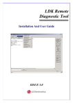
KSU Exterior and Dimension
The following diagram shows the exterior and dimensions of the KSU:
mm
Release 3.5
SBX IP Installation Guide
June 2010
3-5
Chapter 3: KSU Installation
KSU Installation
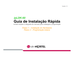
Opening and Closing the Front Cover
Opening the Front Cover
1. Open the cord cover, and turn the screws counter-clockwise to loosen (as shown
in Figure 3-1).
2. Lift the front cover in the direction of the arrow as shown.
Figure 3-1
Release 3.5
Opening the front cover
SBX IP Installation Guide
June 2010
3-6
Chapter 3: KSU Installation
KSU Installation
Closing the Front Cover
1. Insert the front cover into the slot on the KSU (as shown in Figure 3-2).
2. Put the front cover down on the KSU in the direction of the arrow shown.
3. Turn the screws clockwise to tighten and close the Cord Cover.
Figure 3-2
IMPORTANT:
Release 3.5
Closing the front cover
Prior to operation, the front cover of the SBX IP must be closed and
the screws tightened.
SBX IP Installation Guide
June 2010
3-7
Chapter 3: KSU Installation
KSU Installation
Frame Ground Connection
It is very important that the frame of the SBX IP system is grounded:
1. Turn the grounding screw counter clockwise to loosen it (as shown in Figure 3-3).
2. Insert the grounding wire, and tighten the screw.
3. Connect the grounding wire to an appropriate ground source (refer to Caution
below).
Figure 3-3
Grounding the KSU
CAUTION:
•
•
•
•
Release 3.5
The equipment should be connected to an outlet with a protective ground
connection.
For ground wire, green-and-yellow insulation is required. In addition, the
cross-sectional area of the conductor must be more than UL 1015 AWG#18
(1.0mm). It is also recommended that the ground wire be shorter than 1m (3.28 ft).
Proper grounding is very important to protect the SBX IP from external noise, and
to reduce the risk of electrocution in the event of lightning strike.
You must comply with applicable local regulations.
SBX IP Installation Guide
June 2010
3-8
Chapter 3: KSU Installation
KSU Installation
External Backup Battery Installation
In case of power failure, the external backup batteries automatically maintain
uninterrupted power for the SBX IP system. The external batteries must provide 24V
DC; this is generally accomplished by connecting two 12V batteries in a series
arrangement (as shown in Figure 3-4).
Figure 3-4
NOTE:
External Backup Battery Installation
The cable used to connect the battery is supplied with the KSU.
Battery operation is controlled by the PSU. The PSU provides charging current to the
batteries during normal AC power operation at a maximum of about 200mA. PSU
battery operation is halted if the AC power is re-connected, or if the battery voltage is
too low to maintain full-system operation. The external batteries maintains system
operation as needed, depending on several elements such as battery charge status,
condition and capacity of the batteries, and system configuration (that is, number of
station ports).
CAUTION:
•
•
•
•
•
Release 3.5
It is recommended that you use an external backup battery fuse (5A @ 250V)
between the battery and the system.
The recommended battery capacity is 24V/20AH MF. The SBX IP system
generally operates for over 3 hours with batteries that are in good condition.
Carefully check the battery polarity with cable colors (red and blue) when
connecting the battery to the system.
Make sure that you do not short-out the external batteries and cables.
There is a danger of explosion if external batteries are replaced incorrectly. Be
sure replacement batteries are the same as (or equivalent to) those
recommended by the manufacturer. Dispose of used batteries according to the
manufacturer’s instructions.
SBX IP Installation Guide
June 2010
3-9
Chapter 3: KSU Installation
KSU Installation
KSU Mounting
Wall Mounting
1. Install three (3) anchor plugs into the wall using the mounting template included
for accurate placement, as shown in #1-#3 of Figure 3-5.
2. Attach the mounting template with the three (3) screws (included) to the three (3)
anchor plugs #4 of Figure 3-5.
3. Hook the KSU onto the screws, making sure that the system slides down
securely, as shown in Figure 3-6.
1
2
3
Figure 3-5
Release 3.5
Mounting Template
SBX IP Installation Guide
June 2010
3-10
Chapter 3: KSU Installation
KSU Installation
Figure 3-6
Release 3.5
Wall Mounting the KSU
SBX IP Installation Guide
June 2010
3-11
Chapter 3: KSU Installation
KSU Installation
Desktop Mounting
To use the SBX IP system on top of a desk or other flat surface, use the following
procedure:
1. To attach the rubber feet to the bottom of the SBX IP system as shown in Figure
3-7, first remove the protective sticker from the rubber feet.
2. After attaching the rubber feet to the BKSU and EKSU, firmly mount the EKSU
onto the BKSU.
Figure 3-7
Release 3.5
Desktop Mounting
SBX IP Installation Guide
June 2010
3-12
Chapter 3: KSU Installation
Expansion KSU Installation
Expansion KSU Installation
Unpacking
Figure 3-8
Release 3.5
EKSU Carton Contents
SBX IP Installation Guide
June 2010
3-13
Chapter 3: KSU Installation
Expansion KSU Installation
Connecting the Expansion KSU to the Basic KSU
To connect the Expansion KSU to the Basic KSU, perform the following steps:
1. Remove the “dummy” of each KSU.
2. Use the link cable to connect the Basic KSU to the Expansion KSU (as shown
in Figure 3-9).
3. To secure the link cable, turn the screw clockwise to tighten, and then tie the link
cable with tie cable (as shown in Figure 3-10).
Figure 3-9
Release 3.5
Connecting KSUs
SBX IP Installation Guide
June 2010
3-14
Chapter 3: KSU Installation
Expansion KSU Installation
Figure 3-10
EKSU to BKSU Connection
NOTE:
•
•
Release 3.5
If AC power fails, the last SLT port on the EMBU automatically connects to CO1.
If power to the EKSU is turned off while both systems (BKSU and EKSU) are
working properly, the BKSU automatically restarts.
SBX IP Installation Guide
June 2010
3-15
Chapter 3: KSU Installation
Expansion KSU Installation
Expansion KSU Mounting
NOTE:
Do not make any link cable connections between the BKSU and EKSU until they both are
properly wall mounted or rack mounted.
EKSU Wall Mounting
1. Install the EKSU within 5 centimeters of the basic system.
2. Install three (3) anchor plugs into the wall using the mounting template included
for accurate placement. The KSU can be mounted either vertically or horizontally.
3. Screw the included three (3) screws into the three (3) anchor plugs (as shown
in Figure 3-11).
1
2
3
Figure 3-11
Release 3.5
EKSU Mounting Template
SBX IP Installation Guide
June 2010
3-16
Chapter 3: KSU Installation
Expansion KSU Installation
4. Hook the Expansion KSU onto the installed screws, making sure that the system
slides down securely (Figure 3-12.)
Figure 3-12
Release 3.5
EKSU Wall Mounting
SBX IP Installation Guide
June 2010
Chapter 4
Board Installation
While installing boards, be aware of the following:
CAUTION:
•
•
•
Power must be turned OFF before and during board installation.
To protect the system from static electricity, do not touch the boards.
To discharge static, touch a grounded object or wear a grounding strap.
Insert the boards carefully to avoid bending connector pins (male pins on
MBU/EMBU). Misaligning can damage the boards.
To install the board, perform the following steps:
•
•
Before inserting the board, remove the dummy slot (as shown in #1 of Figure 4-1).
Hold the board (as shown in #2 of Figure 4-1), and carefully insert the board in the
direction of the arrow so that the board securely engages with the connector
(CN2) on the main board (as shown in #3).
Figure 4-1
Release 3.5
Board Installation
SBX IP Installation Guide
June 2010
4-2
Chapter 4: Board Installation
Basic Board Installations
Basic Board Installations
Main Board Unit (p/n: 4000-00)
The MBU controls the communication between the peripheral interfaces, supervises all
resources in the system, controls the gain adjustment of the PCM signal, generates the
system tones, and manages system call processing.
Figure 4-2
MBU
Main Board Unit (p/n: 4000-03)
This MBU performs all the same functions as the MBU shown above. This unit was
modified to accommodate expanded capabilities such as the T1/PRI board and the 3x8
Expansion board.
(Also, this unit has been pre-loaded with the 3.0 software, or higher.)
Release 3.5
SBX IP Installation Guide
June 2010
4-3
Chapter 4: Board Installation
Basic Board Installations
NOTE:
If AC power fails, the last SLT port on the MBU automatically connects to CO1.
The MBU is installed in the KSU, and it provides various types of connectors and RJ11
modular jacks for the connection of peripheral boards and miscellaneous functions
(refer to Figure 4-2, Figure 4-3, and Table 4-1).
Figure 4-3
Table 4-1
Connectors
SWITCH/CONNECTOR
CN1
CN2
CN4
CN5
CN6
CN7
CN8
CN13
CN14
Release 3.5
MBU Connection Ports
FUNCTION
KSU Connection to EKSU with Link
cable
3x8 Expansion Installation
MODU Installation
VMIB
JTAG Port for Emulator
PSU Connection (+5V, -5V, +30V)
RS-232C Port Connection
External Relay Contact
VoIB Installation
SBX IP Installation Guide
COMMENT
50 pins
50 pins
20 pins
32 pins
For Test
7 pins
9 pins
4 pins
16 pins
June 2010
4-4
Chapter 4: Board Installation
Basic Board Installations
Table 4-1
Connectors (continued)
SWITCH/CONNECTOR
MJ1
MJ2
MJ2-1
MJ2-2-8
MJ3
PJ1 (Red)
PJ2 (Blue)
SW1
SW2
SW3
SW4
FUNCTION
COMMENT
3 CO Lines Connection
1 DKT or Alarm Sensor
7 DKTs or 7 SLTs Connection
LAN
External MOH Connection
External Page Connection
4 Poles DIP Switch for Software Usage
Lithium Battery ON/OFF Switch for
Memory & RTC Backup
System Reset Button
JTAG Reset Enable/Disable Switch
3 arrays
8 arrays
1 LAN
Default = All ON
Default = OFF
Not Assembled
Modular Jack (MJ1 - MJ3) Pin Assignment
MBU MJ1 (CO)
Table 4-2
MBU1 - 1, 2, 3
CONNECTOR
PIN NUMBER
1, 2
3, 4
5, 6
SIGNAL NAME
n/a
CO-T, CO-R
n/a
MBU MJ2 (Extension)
Table 4-3
MBU MJ2 - 1 (DKT Only)
CONNECTOR
PIN NUMBER
1
2
3, 4
5
6
Release 3.5
SIGNAL NAME
n/a
DKT-T
Alarm_Detection
DKT-R
n/a
SBX IP Installation Guide
June 2010
4-5
Chapter 4: Board Installation
Basic Board Installations
Table 4-4
MBU MJ2 - 2, 3, 4, 5, 6, 7, 8
CONNECTOR
PIN NUMBER
1
2
3, 4
5
6
NOTE:
SIGNAL NAME
n/a
DKT-T
SLT-T, SLT-R
DKT-R
n/a
When installing DKTs or SLTs on Hybrid Ports (MJ2-2,3,4,5,6,7,8), keep the
pin assignment (as shown above in Table 4-4). Otherwise the DKTs or SLTs will not
operate normally.
Table 4-5
Terminal DKT
CONNECTOR
PIN NUMBER
1
2
3, 4
5
6
Table 4-6
SIGNAL NAME
n/a
RING
Reserved
TIP
n/a
Terminal SLT
CONNECTOR
PIN NUMBER
1, 2
3, 4
5, 6
SIGNAL NAME
n/a
TIP, RING
n/a
CN13 Pin Assignment (Relay Contact)
Table 4-7
CN13
CONNECTOR
Release 3.5
NO
SIGNAL NAME
1
2
3
4
Relay 1 - pin 1
Relay 1 - pin 2
Relay 2 - pin 1
Relay 2 - pin 2
SBX IP Installation Guide
June 2010
4-6
Chapter 4: Board Installation
Basic Board Installations
Table 4-8
MJ3 Pin Assignment (LAN)
CONNECTOR
PIN NUMBER
SIGNAL NAME
4, 5, 7, 8
1
2
3
6
TX+
TXRXRX+
FUNCTION
reserved
Transmit Data
Transmit Data
Receive Data
Receive Data
Switch, LED, and Connector
Table 4-9
SWITCH
1-1
1-2
1-3
1-4
SW1 Functions
FUNCTION
Administration Programming Access
Command/Event Trace (Software Testing)
Simplified Message Desk Interface control
(SMDI - Voice Mail)
Database Default on Power Up
OFF
ON (DEFAULT)
Disable
Enable
SMDI ON
Enable
Disable
SMDI OFF
Disable
Enable
Before programming the system, Switch 1-4 (as shown above in Table 4-9) should be
set to ON. The power should then be cycled OFF, and back ON to initialize the default
system database. Once the database has been initialized, switch 1-4 should be placed
in the OFF position to protect the database.
To protect the RAM/RTC data, set the SW2 lithium battery switch to the ON position,
then install the option boards to the MBU.
CAUTION:
•
•
•
•
Release 3.5
The SW2-DIP switch should be set to the ON position to protect the system
database in case of power failure.
Replace the batteries (when needed) with the same or equivalent type
recommended by the manufacturer. The system will not function normally if the
batteries are replaced incorrectly.
Dispose of used batteries according to manufacturer’s instructions and/or local
government regulations.
After the system powers up and initializes, the 4th pole of SW1 should be set to
the OFF to position to protect the features being programmed in Admin
Programming.
SBX IP Installation Guide
June 2010
4-7
Chapter 4: Board Installation
Basic Board Installations
SBX 25-Pair Installation Cable Pinouts
Release 3.5
SBX IP Installation Guide
June 2010
4-8
Chapter 4: Board Installation
Expansion Main Board Unit (EMBU)
Expansion Main Board Unit (EMBU)
Expansion MBU (p/n: 4002-00)
The Expansion Main Board Unit provides the following features:
•
•
•
•
•
•
•
DKT and SLT Interface circuits
Ring Generation circuit
External Relay contacts for LBC or general purpose
Peripheral Device Decoding circuit
Master Clock Generation circuit
PFT circuit [CO1 ⇔ the last SLT port (STA8)]
PCM Voice Processing circuit with ACT2 (ASIC, voice switching including DSP)
device for PCM tone generation and PCM gain control.
EKSU p/n (4002-03) supports
16 digital stations
Figure 4-4
EMBU
Expansion MBU (p/n: 4002-03)
This “all digital” EMBU provides the same features and functionality as the EMBU
described above. This unit was modified to accommodate expanded system
capabilities such as the DTIB16 card which supports 16 digital stations.
Release 3.5
SBX IP Installation Guide
June 2010
4-9
Chapter 4: Board Installation
Expansion Main Board Unit (EMBU)
NOTE:
•
If AC power fails, the last SLT port on the EMBU automatically connects to
CO1.
•
If power to the EKSU is turned off while both systems (BKSU and EKSU) are
working properly, the BKSU automatically restarts.
Figure 4-5
Table 4-10
Connector/Modular Jack/Switch Functions
SWITCH/CONNECTOR
CN1
CN2
CN7
CN13
MJ1
MJ2
Table 4-11
LED
LED1 (Blue)
Release 3.5
EMBU Connection Ports
FUNCTION
KSU Connection from BKSU with Link cable
CO and Extension Board (3x8 Expansion) installation
PSU connection
External Relay contact
3 CO connection
16 DKT
COMMENT
50 Pins
50 Pins
7 Pins
4 Pins
3 Arrays
8 Arrays
LED Indications
DESCRIPTION
Periodic Toggle - ON, 300 msec; OFF, 300 msec
SBX IP Installation Guide
June 2010
4-10
Chapter 4: Board Installation
Expansion Main Board Unit (EMBU)
Modular Jack (MJ1 - MJ3) Pin Assignment
EMBU MJ1(CO)
Table 4-12
EMBU MJ1 - 1, 2, 3
CONNECTOR
PIN NUMBER
1, 2
3, 4
5, 6
Table 4-13
PIN NUMBER
Rel. 3.0
-------->
1
2
3, 4
5
6
2&5
3, 4
SIGNAL NAME
n/a
DKT-T
SLT-T, SLT-R
DKT-R
n/a
DKT1
DKT2
When installing DKTs or SLTs on Hybrid Ports, (MJ2 -2,3,4,5,6,7,8), keep the
pin assignment (as shown above in Table 4-13). Otherwise the DKTs or SLTs
will not operate normally.
Table 4-14
Terminal DKT
CONNECTOR
PIN NUMBER
1
2
3, 4
5
6
Release 3.5
n/a
CO-T, CO-R
n/a
EMBU MJ2 - 1, 2, 3, 4, 5, 6, 7, 8
CONNECTOR
NOTE:
SIGNAL NAME
SIGNAL NAME
n/a
RING
reserved
TIP
n/a
SBX IP Installation Guide
June 2010
4-11
Chapter 4: Board Installation
Expansion Main Board Unit (EMBU)
Table 4-15
Terminal SLT
CONNECTOR
PIN NUMBER
1, 2
3, 4
5, 6
SIGNAL NAME
n/a
TIP, RING
n/a
CN13 Pin Assignment (Relay Contact)
Table 4-16
CN13
CONNECTOR
Release 3.5
NO
SIGNAL NAME
1
2
3
4
Relay 1 - pin 1
Relay 1 - pin 2
Relay 2 - pin 1
Relay 2 - pin 2
SBX IP Installation Guide
June 2010
4-12
Chapter 4: Board Installation
CO Line and Extension Boards
CO Line and Extension Boards
3x8 Expansion Board (3 CO Line and 8 Hybrid)
The 3x8 Expansion Board can be installed on the CN2 connector of the MBU or EMBU,
and provides three (3) CO/PBX Loop Start CO Line interfaces that support Pulse/DTMF
signaling. Each interface contains ring and loop current circuits, A/D and D/A
conversions, as well as pulse signaling circuitry.
This board also provides eight Hybrid ports (eight DKTs or eight SLT interfaces), and
can detect FSK signal for incoming Caller ID, DTMF signal for incoming caller ID, and
a call progress tone. It also provides three (3) on-hook connection paths for CID/SMS.
BOARD
CONNECTOR
TYPE
LINE
3x8 Expansion 3 CO & 8 SLT or 8 DKT
Figure 4-6
Release 3.5
RJ11
DESCRIPTION
CABLE
3 CO Line and
DKT : 4 wire
8 Hybrid Interface CO, SLT : 2 wire
3x8 Expansion Board
SBX IP Installation Guide
June 2010
4-13
Chapter 4: Board Installation
CO Line and Extension Boards
Modular Jack (MJ1-MJ2) Pin Assignment
Table 4-17
3x8 Expansion Board MJ1 - 1, 2, 3
CONNECTOR
PIN NUMBER
SIGNAL NAME
1, 2
3, 4
5, 6
Table 4-18
n/a
CO-T, CO-R
n/a
3x8 Expansion Board MJ2 - 1, 2, 3, 4, 5, 6, 7, 8
CONNECTOR
PIN NUMBER
SIGNAL NAME
1
2
3, 4
5
6
n/a
DKT-T
SLT-T, SLT-R
DKT-R
n/a
3x16 Expansion Board (3 CO Line and 16 Digital)
IMPORTANT:
The 3x16 Expansion Board can ONLY be installed on the “modified”
MBU (p/n 4000-03) or EMBU (p/n 4002-03)
The 3x16 Expansion Board can be optionally installed on the CN2 connector of the
“modified” MBU or EMBU, and provides three (3) CO/PBX Loop Start CO Line
interfaces that support Pulse/DTMF signaling. Each interface contains ring and loop
current circuits, A/D and D/A conversions, as well as pulse signaling circuitry.
This board also provides 16 Digital ports (16 DKT interfaces), and can detect FSK
signal for incoming Caller ID, DTMF signal for incoming caller ID, and a call progress
tone. It also provides three (3) on-hook connection paths for CID/SMS.
BOARD
LINE
3x16
Expansion
3 CO & 16 DKT
NOTE:
Release 3.5
CONNECTOR
TYPE
RJ11
DESCRIPTION
CABLE
3 CO Line and
DKT : 4 wire
16 Digital Interface CO : 2 wire
The modular jack pin assignments are the same as the 3x8 Expansion Board,
see Table 4-17andTable 4-18 above.
SBX IP Installation Guide
June 2010
4-14
Chapter 4: Board Installation
Other Board Installations (optional)
Other Board Installations (optional)
Digital Telephone Interface Board (DTIB16)
The Digital Telephone Interface Board (DTIB) can be optionally installed to provide
digital voice and data communications to/from 16 digital telephones. An RJ11 type
female connector is mounted on the front edge of the board for connection to the station
interfaces.
•
•
•
The EMBU (p/n 4002-03) can support two DTIB16 boards to increase the number
of ports to 32.
Notice the board-specific pinouts shown in Figure 4-7 .
The DTIB16 is configured in PGM 101-103.
DTIB16
Figure 4-7
Release 3.5
Installation of the DTIB16 Board
SBX IP Installation Guide
June 2010
4-15
Chapter 4: Board Installation
Other Board Installations (optional)
Modem Function Unit (MODU)
MODU provides analog modem connection. The MODU can be optionally installed on
the MODU connectors (CN4) of the MBU. The MODU supports Bell, ITU-T, V.34,
V.32BIS, and V.90 protocols at a speed rate of 300bps up to 33Kbps. It also supports
automatic rate negotiation.
Figure 4-8
Release 3.5
Installation of the MODU Board
SBX IP Installation Guide
June 2010
4-16
Chapter 4: Board Installation
Other Board Installations (optional)
T1/PRI Interface Board
The T1/PRI interface board board provides a full T1/PRI digital trunk interface and 8
hybrid stations. The board also supports both full and fractional T1/PRI circuits in
clusters of 4.
This interface supports either 24 PCM channels for T1 or 23 PCM channels for PRI.
Nine (9) loop start CO lines can be used in addition to the T1/PRI channels. The T1/PRI
includes the Ethernet port.
This board can be used as either a T1 or a PRI by changing the onboard DIP switch.
By default, switch SW4 is set to the ON position (PRI).
CAUTION:
The T1/PRI board can only be used with MBU p/n: 4000-03.
LED
9
SW4
The Default is ON (PRI)
PRI
T1
1 0
11
1 2
1 3
14
1 5
1 6
S TA S TA S TA S TA S TA S TA S TA S TA
LD1 LD2 LD3 LD4 LD5 LD6 LD7 LD8 LD9
The Default is all OFF
SW3 System Reset button
Release 3.5
SBX IP Installation Guide
June 2010
4-17
Chapter 4: Board Installation
Other Board Installations (optional)
LED Indications
LED
SPECIFICATION
LED1
PRI - In Use and blinking slowly if active
T1 - In Use
LED2
ON - RX Carrier Loss
LED3
ON - Out of frame
LED4
ON - Yellow Alarm
LED5
ON - RX all 1
LED6
ON - Loop back mode
LED7
PRI - ON: Multiframe Establish Alarm
T1 - ON: Blinking slowly if active
LED8
ON - reserved
LED9
ON - TE
LED10*
Blue ON - In Use of one of 8 HYBRID extensions of PRHB8 board
* LED 10 is not related to PRI/T1 trunk operation. It is only related to
8 extensions use state of PRHB8 board
Release 3.5
SBX IP Installation Guide
June 2010
4-18
Chapter 4: Board Installation
Other Board Installations (optional)
VoIB -- Voice Over Internet Protocol Board (4ch)
The VoIB can be optionally installed on the MBU, and provides four VoIP channels.
The length of the Ethernet cable should be less than ten (10) meters.
Figure 4-9
VoIB
The VoIB can be installed on the basic MBU, and provides the Ethernet interface for
software applications and VoIP features with an optional VoIP daughter board.
The VoIB has the capacity for maximum four (4) channels with one (1) VoIB. The VOIU
provides an additional four (4) VoIP channels.
ITEM
LAN Interface
Speed
Duplex
VoIP Protocol
Voice Compression
Voice/Fax Switching
Echo Cancellation
Dual SIP / H.323
protocol support
ITU-T H.323 v4 & H.450
standard compliance
Release 3.5
SPECIFICATION
10 Base-T Ethernet (IEEE 802.3)
10/100 auto-negotiation, 100 Mbps recommended
Half Duplex or Full Duplex (Auto-Negotiation)
H.323 Revision 4
G.711/G.726/G.729/ G.723.1
T.38
G.165
-Supports H.323 fast connect, early H.245, and H.245 tunneling
Supports H.323 Gatekeeper register, direct and route calls
Inband / out of band DTMF transmission
SBX IP Installation Guide
June 2010
4-19
Chapter 4: Board Installation
Other Board Installations (optional)
ITEM
SIP RFC 2543/3261
standard compliance
Supports IPKTS Protocol
for Vertical IP phones
Codecs
NAT friendly for IP phones
SPECIFICATION
Supports Inband / RFC 2833 / Out of band (INFO) DTMF
transmission
-G.711A/u-law, G.723.1(5.3k/6.3k), G.729/G.729A
--
Various switch and connector functions
SWITCH/CONNECTOR
SW1
SW2
CN1
CN2
CN3 and CN4
CN5
MJ1
LED
LED1 (yellow)
LED2 (yellow)
LED3 (yellow)
LED4 (yellow)
LED5 (yellow)
LED6 (yellow)
LED7 (yellow)
LED8 (yellow)
LED9 (red)
LED10 (red)
LED11
MJ1-LD2 (yellow)
MJ1-LD1 (green/orange)
Release 3.5
FUNCTION
VoIB Reset Switch for CPU (S32510A)
Pole 2: Boot mode selection, others: reserved.
Default: Pole 2 (ON), Others (OFF)
JTAG (Joint Test Action Group) for debug
RS-232C Trace Tool Connection
VOIU Board Connection
MBU Connection
Network (RJ-45) Cable Connection
SPECIFICATION
Channel1 seize indication LED (ON:Busy, OFF:Idle)
Channel2 seize indication LED (ON:Busy, OFF:Idle)
Channel3 seize indication LED (ON:Busy, OFF:Idle)
Channel4 seize indication LED (ON:Busy, OFF:Idle)
Channel5 seize indication LED (ON:Busy, OFF:Idle)
Channel6 seize indication LED (ON:Busy, OFF:Idle)
Channel7 seize indication LED (ON:Busy, OFF:Idle)
Channel8 seize indication LED (ON:Busy, OFF:Idle)
VOIU DSP operation status LED (ON: Normal, OFF: Fail)
VoIB DSP operation status LED (ON: Normal, OFF: Fail)
DSP HINT interrupt LED (ON: Active, OFF: Idle)
Speed Status LED (OFF: 10Mbps)
Link Status LED (ON: Link, Flashing: Data Transfer)
SBX IP Installation Guide
June 2010
4-20
Chapter 4: Board Installation
Other Board Installations (optional)
Pin assignment
Table 4-19
MJ3 Pin Assignment (LAN)
CONNECTOR
PIN NUMBER
4, 5, 7, 8
1
2
3
6
NOTE:
SIGNAL NAME
TX+
TXRXRX+
FUNCTION
RESERVED
Transmit Data
Transmit Data
Receive Data
Receive Data
10BASE-T runs on Category 5 UTP or higher.
VOIU -- Internet protocol unit (4ch)
The VOIU can be optionally installed on the VoIB. It provides four (4) VoIP channels.
Figure 4-10
Release 3.5
Installation of the VOIU Board
SBX IP Installation Guide
June 2010
4-21
Chapter 4: Board Installation
Other Board Installations (optional)
Voice Mail Interface Board (VMIB)
The Voice Mail Interface Board (VMIB) can be optionally installed on CN5 of the MBU.
It provides the capability for system announcements, UCD announcements, and user
greetings.
Figure 4-11
Table 4-20
Installation of the VMIB Board
Voicemail Specifications
ITEM
Channel
Max Record Time:
Prompt
System Greeting (announcement)
User Record Time
Max Number of User Voice Messages
Number of system greeting (for all users in system)
Release 3.5
2-hour VMIB
8-hour VMIB
4 Channels
4 Channels
8 Min.
24 Min.
99 Min.
800
01-70
10 Min.
40 Min.
480 Min.
800
01-70
NOTE:
MBU SW1-4 and SW2 control the protection of recorded messages.
NOTE:
You can tell the 8-hour VMIB from the 2-hour VMIB by checking the label on
the VMIB. The 8-hour VMIB is labeled 4000-80.
SBX IP Installation Guide
June 2010
4-22
Chapter 4: Board Installation
Other Board Installations (optional)
Release 3.5
SBX IP Installation Guide
June 2010
Chapter 5
Terminal Connection and Wiring Method
Terminal and Doorbox Models
MODEL
DESCRIPTION
7208D
8-button digital telephone
7224D
24-button digital telephone
--
48-button DSS Console
--
2-port digital Doorbox
7208D
Figure 5-1
Release 3.5
Vertical 7208 Telephone for SBX IP
SBX IP Installation Guide
June 2010
5-2
Chapter 5: Terminal Connection and Wiring Method
Terminal and Doorbox Models
7224D
Figure 5-2
DSS
Figure 5-3
Release 3.5
Vertical 7224 Telephone for SBX IP
Doorbox
Vertical DSS and Doorbox for SBX IP
SBX IP Installation Guide
June 2010
5-3
Chapter 5: Terminal Connection and Wiring Method
Terminal Cabling Distance
Terminal Cabling Distance
Figure 5-4
Release 3.5
Terminal Cable Distance
SBX IP Installation Guide
June 2010
5-4
Chapter 5: Terminal Connection and Wiring Method
Basic Terminal Connection
Basic Terminal Connection
DKT and DSS
Figure 5-5
Table 5-1
Connecting a DKT to the system
DKT and DSS Connection Pin Assignment
CONNECTOR
PIN NUMBER
NO
SIGNAL NAME
1
2
3, 4
5
6
n/a
DKT-T
Reserved
DKT-R
n/a
SLT
Figure 5-6
Table 5-2
SLT Connection Pin Assignment
CONNECTOR
Release 3.5
Connecting an SLT to the system
PIN NUMBER
NO
SIGNAL NAME
1, 2
3, 4
5, 6
n/a
TIP, RING
n/a
SBX IP Installation Guide
June 2010
Basic Terminal Connection
5-5
Chapter 5: Terminal Connection and Wiring Method
Doorbox
The Doorbox is an intercom unit that can be installed at the entrance to a building for
communication between visitors and employees inside.
By pressing a CALL button, a visitor can communicate with a person inside the building
who has a phone with a “call coverage” flex button associated with the Doorbox.
Installation
Release 3.5
SBX IP Installation Guide
June 2010
Basic Terminal Connection
5-6
Chapter 5: Terminal Connection and Wiring Method
Operating Instructions
The following examples describe how calls are handled when sent through the
Doorbox.
Call FROM the Doorbox
A visitor can press the CALL button once or the External switch once, depending
on the setup.
•
The visitor hears music from the Doorbox until station user answers the call.
•
The station with the call coverage flexible button associated with the Doorbox
also rings, and the call coverage button LED illuminates.
HINT: Refer to the Programming Guide ("Intercom Box Signaling" in Station Attributes).
•
The station user answers the call by going off-hook using the handset or by
pressing the SPEAKER button for speakerphone operation.
Call TO the Doorbox
The station user can go off-hook and press a flexible button that is
pre-programming with the Doorbox station number, or dial the number
associated with the doorbox.
Release 3.5
SBX IP Installation Guide
June 2010
5-7
Chapter 5: Terminal Connection and Wiring Method
Connecting Additional Terminals
Connecting Additional Terminals
The MBU provides connections for one external music source, one external page port,
one relay contact, and an alarm detection input monitor through the PJ1 (RED, External
MOH) and PJ2 (BLUE, External Page) audio jacks and an MJ3 (RJ11 Modular Jack)
as shown in Figure 5-7.
Figure 5-7
Release 3.5
Adding Terminals
SBX IP Installation Guide
June 2010
Connecting Additional Terminals
5-8
Chapter 5: Terminal Connection and Wiring Method
External Music Source Wiring
The MBU accommodates one external music port through a PJ1 (RED) audio jack.
Relay Contacts
The MBU/EMBU provides two (2) relay contacts that are used for a loud bell or other
general purposes through pin No. 1-4 of CN13.
External Paging Port Wiring
The MBU supports one external paging port through a PJ2 (BLUE) audio jack.
Alarm Detection Wiring
The MBU provides an external alarm detection input, which can be used to transmit
notification to extensions when the external switch is closed or opened (programmable
through Admin Programming). This alarm detection input is provided through MJ2-1 pin
3-4 of the MBU.
Release 3.5
SBX IP Installation Guide
June 2010
5-9
Chapter 5: Terminal Connection and Wiring Method
Cable Wiring
Cable Wiring
Wall Mount Wiring
To install wall mount wiring, perform the following steps:
1. Make sure that the BKSU and EKSU have been installed correctly (see Chapter 3
- KSU Installation).
2. Connect cables to CO/STA and MOH/RS-232C ports, as shown in Figure 5-8.
3. Connect the power cord and the battery cable.
4. Remove plastic filter pieces.
5. Using the tie cable provided, tie all the cables and the power cord (as appropriate)
through the tie slot at the bottom-right side of the KSUs.
6. Close the covers of the KSUs, then close the cord cover.
Figure 5-8
Release 3.5
Wall Mount Wiring
SBX IP Installation Guide
June 2010
5-10
Chapter 5: Terminal Connection and Wiring Method
Cable Wiring
Rack Mount Wiring
1. Check that the BKSU and EKSU have been installed correctly (see Chapter 3 KSU Installation).
2. Connect cables to the CO/STA and MOH/RS-232C ports, as shown in Figure 5-9.
3. Connect the power cord and the battery cable.
4. Remove the plastic filter pieces.
5. Using the tie cable provided, tie all the cables and the power cord (as appropriate)
through the tie slot at the bottom-right side of the KSUs.
6. Close the covers of the KSUs and close the cord cover.
Figure 5-9
Release 3.5
Rack Mount Wiring
SBX IP Installation Guide
June 2010
5-11
Chapter 5: Terminal Connection and Wiring Method
IP Phones on the SBX IP
IP Phones on the SBX IP
Supported IP phones:
•
•
•
NOTE:
IP7008D, IP7024D, IP7024LD
Nomad IP (Wireless)
Nomad SP (Soft Phone)
This section specifically applies to setting up the IP7000-series telephones only.
Minimum requirements
System
•
•
•
SBX IP system with VoIP card
Static IP address for VoIP card. If NAT is used, it must be a 1-to-1 NAT
Separate IP address for the KSU's LAN port for system administration
NOTE:
•
•
No VoIP communication takes place on the KSU LAN port.
KSU version 1.0Cf
VoIP card software version B.1Dq.
Installed Environment
•
•
•
Release 3.5
CAT5E (or higher) patch cords from VoIP card to LAN switch
No hubs
Adequate bandwidth for the anticipated number of H.323 VoIP calls
SBX IP Installation Guide
June 2010
5-12
Chapter 5: Terminal Connection and Wiring Method
IP Phones on the SBX IP
IP endpoint licensing
Nomad SP requires a per-seat license. Two seats are automatically included; you do
not have to install activation codes for these two seats.
IP7000 series and NomadIP wireless phones do not require a license.
NOTE:
Entering IP address information to the KSU database from a digital phone is
performed differently from programming IP settings for an IP remote phone.
Digital stations on KSU: Enter digits in groups of 3, with no punctuation or decimal.
Example: To program the address 192.168.1.3, dial 192168001001
IP phone: Enter digits with an asterisk [*] as the decimal.
Example: To program the address 192.168.1.10, dial 192*168*1*10
IP Addressing
To begin, obtain IP addresses from the network administrator for the location in which
you are setting up the SBX IP system. Note them in the table provided below for
reference while programming the system:
Table 5-3
IP Addresses for current system
VoIP card (VoIB)
KSU LAN port
IP Phone
Your PC
(may be DHCP)
(may be DHCP)
IP Address
Subnet Mask
Default Gateway
Release 3.5
SBX IP Installation Guide
June 2010
5-13
Chapter 5: Terminal Connection and Wiring Method
IP Phones on the SBX IP
Figure 5-10
•
•
•
You will also need a 24-button SBX digital telephone to set up the system.
For a typical test-bench or demonstration setup, you need 4 connections to a LAN
switch, each via a straight-through CAT5E patch cord as shown in Figure 5-10.
You may use the IP address information shown in Table 5-4 to set up a closed
demo of the IP phone.
NOTE:
These addresses will not function in a wide-area network or the Internet. They
are for testing and demonstration purposes only:
Table 5-4
IP Addresses for testing and demonstration only
IP Address
Subnet Mask
Default Gateway
Release 3.5
System Setup
VoIP card
KSU LAN port
IP Phone
Your PC
192.168.1.4
192.168.1.3
192.168.1.5
192.168.1.2
255.255.255.0
255.255.255.0
255.255.255.0
255.255.255.0
192.168.1.1
192.168.1.1
192.168.1.1
192.168.1.1
SBX IP Installation Guide
June 2010
5-14
Chapter 5: Terminal Connection and Wiring Method
IP Phones on the SBX IP
Preparation
1. Before starting, verify that the VoIP (VoIB) card is installed into the system
properly (see page 4-18), and that the card is recognized in the KSU database.
2. KSU DIP switches must be set to enable the system to retain programming
changes.
3. Set the PC IP address, default gateway, and subnet mask as noted in Table 5-3.
4. Set the KSU's IP addressing using PGM 108 when logged into KSU
administration from the 24-button digital attendant station (Station 100 by default).
This assigns the IP address to the KSU's LAN port. The configuration for the VoIP
card begins here.
PCAdmin Connection
Follow the PCAdmin User's Guide or the Tech Tip regarding setting up PCAdmin to
establish connection between the SBX system and PCAdmin. Remember, when
connecting to the SBX IP using a LAN switch, a straight-through patch cable (not a
crossover cable) is required.
Configuring The VoIP Card Using PCAdmin
NOTE:
Digital phone-based programming is shown on page 5-22.
1. Double-click Pre-programmed > Configuration
Release 3.5
SBX IP Installation Guide
June 2010
IP Phones on the SBX IP
5-15
Chapter 5: Terminal Connection and Wiring Method
2. Right-click on the VoIB, then select Logical Assignment.
3. In Logical Assignments, right-click VoIB and Select (Virtual VoIB) => Append to
Station. A notation of 99 will be entered in the STA Board field.
4. Click Update.
5. In VoIB Gateway > VoIB Gatekeeper Settings enter the IP Address, Default
Gateway, and Subnet Mask that you are assigning to the VoIP card per the
worksheet.
Release 3.5
SBX IP Installation Guide
June 2010
IP Phones on the SBX IP
5-16
Chapter 5: Terminal Connection and Wiring Method
6. Click Update.
7. In RSG IP Programming, double-click VoIB Slot for RSG/IP.
8. Select the VoIB card (10), then click the > button to move the selection to the
right-hand column.
You will see the card slot on the right side.
Release 3.5
SBX IP Installation Guide
June 2010
IP Phones on the SBX IP
5-17
Chapter 5: Terminal Connection and Wiring Method
9. Click Update.
10. Select the card from the VoIB Slot dropdown.
11. Select 2 for the number of channels to be used for IP Phones from the Channel
Number dropdown.
12. Click Update Channel.
13. Select the 2 from the IP Phone Number dropdown, then click Update Num.
This tells the system to assign 2 IP stations.
Release 3.5
SBX IP Installation Guide
June 2010
5-18
Chapter 5: Terminal Connection and Wiring Method
IP Phones on the SBX IP
14. Click Update.
15. Reset the KSUDouble-click RSG/IP Programming > IP Phone Attributes.
16. Double-click on bin 1 (row 1).
Release 3.5
SBX IP Installation Guide
June 2010
IP Phones on the SBX IP
5-19
Chapter 5: Terminal Connection and Wiring Method
17. Enter the MAC address which you will find labeled on the bottom of the IP phone,
then click Update.
NOTE:
Be sure to include the colons in the MAC address.
You do not need to program the other data values in PGM 386 for IP7000 remote
phones. The ID and Password values will be used when you are configuring a Nomad
SP (Soft Phone).
Release 3.5
SBX IP Installation Guide
June 2010
5-20
Chapter 5: Terminal Connection and Wiring Method
IP Phones on the SBX IP
Configuring IP phone settings
To verify connectivity to the VoIP card, you should ping the VoIP card from where the
phone is located.
Setting up the IP Phone will vary depending upon the network infrastructure, IP
Address schema, and location of the system. You need the following information to
properly configure the IP Phone:
•
•
•
•
The IP Address of the VoIP card.
Whether the IP Address information is supplied dynamically (DHCP) or statically
An IP Address and Subnet Mask for the IP Phone (either static or DHCP).
The Default Gateway IP Address (either static or DHCP).
NOTE:
If IP Addresses are static, you will need to obtain the correct IP Address,
Subnet Mask, and Default Gateway information from the IT Administrator.
Connect the IP Phone to the local network. It can be powered with an AC power
adapter or a port on a POE (Power Over Ethernet) switch. The power adaptor is part
#6899-PS. When powered, the IP Phone completes its boot sequence, then attempts
to connect to the VoIP Card. If the phone is unable to connect to the VoIP card, the
following message is displayed:
NO RESPONSE FROM MFIM
SET [*] - RESTART [#]
1. Press * to begin configuring the phone.
2. Use the Volume + and - to navigate the settings.
3. Enter information as follows:
•
If you are prompted for a password: Dial 147*
•
At MODE[R/L] ? (This is the Remote/Local Setting). All IP Phones are
considered remote to the SBX IP no matter where they are physically or
logically. Set the mode to REMOTE. Press # until the display shows:
MODE[R/L] ?
[REMOTE] - CHANGE[#]
4. Press Hold/Save to store the setting as REMOTE.
5. Press the Volume + until DHCP ? appears.
NOTE:
Release 3.5
If IP Addressing is assigned via DHCP, this should be enabled.
If IP Addressing is Static, this should be disabled.
SBX IP Installation Guide
June 2010
IP Phones on the SBX IP
5-21
Chapter 5: Terminal Connection and Wiring Method
6. Press # until the display shows the correct state.
7. Press Hold/Save to retain the entry.
8. Press the Volume + until MFIM IP ADDRESS (DOT:*) appears. This is the VoIB IP
Address Field. MFIM = VoIB. Enter the IP Address on the dial pad. Press the * to
enter a “.” (dot). For example, to enter 192.168.1.10, dial 192*168*1*10. Press
Hold/Save to retain the entry.
MFIM IP ADDRESS(DOT:*)
xxx.xxx.xxx.xxx (The VoIB IP Address)
9. Press the Volume + until ROUTER IP ADDRESS(DOT:*) appears. This is the
Default Gateway IP Address Field. If IP Addressing is being assigned, you won't
need to program this field. If IP Addressing is statically assigned, enter the IP
Address of the Default Gateway and press Hold/Save.
ROUTER IP ADDRESS(DOT:*)
xxx.xxx.xxx.xxx (Default Gateway IP Address)
10. Press the Volume + until PHONE NET MASK(DOT:*) appears. This is the Subnet
Mask associated with the IP Address of the phone. If IP Addressing is being
dynamically assigned, you won't need to program this field. If IP Addressing is
statically assigned, enter the IP Address of the Default Gateway and press
Hold/Save.
PHONE NET MASK(DOT:*)
xxx.xxx.xxx.xxx (Subnet Mask)
11. Press the Volume + until PHONE IP ADDRESS(DOT:*) appears. This is the
station IP Address Field. If IP Addressing is being dynamically assigned, you
won't need to program this field. If IP Addressing is statically assigned, enter the
IP Address of the station and press Hold/Save.
PHONE IP ASSIGNED(DOT:*)
xxx.xxx.xxx.xxx (Station IP Address)
12. When these fields have been completed, press the Speaker button to reboot the
IP Phone. The phone will contact the VoIP card and register to the system. It
receives its station number assignment from the KSU.
Release 3.5
SBX IP Installation Guide
June 2010
5-22
Chapter 5: Terminal Connection and Wiring Method
IP Phones on the SBX IP
In this example, the IP address and station number information appears after two IP
phones have registered to the system:
13. Test the IP phone by dialing an extension number.
Programming VoIP card settings from a digital station
This is an alternative to PCAdmin programming (shown in the preceding section).
Disregard this section if you have configured the IP phone using PCAdmin.
1. Enter KSU programming from the digital attendant phone.
2. Press PGM.
3. Dial 103 (Logical Slot Assign).
4. Press Flex Button 2 (STA).
5. What to enter will depend on what cards are installed. If there are two 3x8
Expansion cards installed the display will show 01 02 .. .. ..
Dial 01 02 99 to assign station ports to the VoIB.
6. Click Save.
Release 3.5
SBX IP Installation Guide
June 2010
5-23
Chapter 5: Terminal Connection and Wiring Method
IP Phones on the SBX IP
Assign IP Address to the VoIB
1. Press PGM.
2. Dial 340 (VoIB Attributes).
3. Press Flex Button 1 (IP ADDR).
4. Dial the IP Address (e.g., 192.168.1.10 Dial 192168010010).
5. Click Save.
6. Press Flex Button 2 (Gateway ADDR) - Mandatory.
7. Dial the default Gateway for the VoIB (ex: for 192.168.1.1 dial 192168001001).
8. Click Save.
9. Press Flex Button 3 (Subnet Mask).
10. Dial the Subnet Mask (ex: for 255.255.255.0 dial 255255255000).
11. Click Save.
VoIB Slot/Port Usage Assignment
1. Press PGM.
2. Dial 380 (VoIB Slot Assignment).
3. Press Flex Button (VoIB Slot).
4. Dial 10 (Slot Number to Program).
5. Click Save.
6. Press Flex button 2 (RSG/IP channel Assign).
7. Dial 10 (Slot Number).
8. Dial 4 (or number of channels to reserve for IP Phones).
9. Click Save.
VoIB IP Station Assignment
1. Press PGM.
2. Dial 381 (RSG/IP No Assign).
3. Press Flex Button 2.
4. Dial the number of IP stations you wish to program (e.g., 04).
5. Click Save.
6. Reset the system and VoIP card.
Release 3.5
SBX IP Installation Guide
June 2010
5-24
Chapter 5: Terminal Connection and Wiring Method
IP Phones on the SBX IP
Program IP Phone Attributes - The number of bins available to program will
correspond to the number of IP phones programmed in PGM 381.
1. Press PGM.
2. Dial 386 (IP Phone Attrib).
3. Dial the Bin Number (for example, 01 This would be the first IP station).
4. Press Flex Button 1.
5. Dial the MAC Address of the IP Phone.
NOTE:
* = A, # = B, NAV Left = C, NAV Right = D, NAV Up = E, NAV Down = F
6. Click Save.
Release 3.5
SBX IP Installation Guide
June 2010
Chapter 6
Starting the SBX IP System
Before Starting the SBX IP System
In preparation for programming, perform the following steps:
1. Turn the DIP switch (SW2) ON prior to installing the MBU, to protect the system
data in case of power failure.
2. Check that the DIP switch (SW1) of the MBU is set to All ON.
3. Plug the AC power cord into the SBX IP system and AC outlet.
4. Program the Nation Code (PGM 100) as applicable.
5. Reset the SBX IP system.
6. Set the 4th pole (SW1) of the MBU to OFF when the system operates normally, to
protect programmed features after system power-up and initialization.
Release 3.5
SBX IP Installation Guide
June 2010
6-2
Chapter 6: Starting the SBX IP System
Basic Programming
Basic Programming
The SBX IP system can be programmed to meet individual needs. There are two ways
to perform Admin Programming:
•
•
PC Admin - Refer to the PC Admin Programming Manual.
DKT - In this manual, DKT (Station 100) Admin Programming is described.
DKT Programming
All programming is done at one station (Station 100, Station Port #00, by default) using
the 7224D Digital Key Telephone.
Additional programming stations may be assigned (PGM 113 - FLEX 1), but only one
DKT can be active in the programming mode at any one time.
NOTE:
All programming must be performed from a 24-button phone or the PCAdmin
software program.
When in programming mode, Station 100 does not operate as a normal telephone, but
instead works as a programming instrument with all the buttons redefined as follows:
•
•
•
Release 3.5
Dial Pad Keys - used to enter numerical information in the various data fields.
Flexible Buttons (the 24 buttons located on the right side of the phone) - used to
indicate a specific data field and to enter information.
Soft Buttons (BACK / DELETE / SAVE) - used to go back / delete data / save data
input.
SBX IP Installation Guide
June 2010
Basic Programming
6-3
Chapter 6: Starting the SBX IP System
Button Explanation
The following graphic and its associated table describe the buttons and function keys.
(Refer to the IP7208D/IP7024D User Guide for detailed information and operation
instructions.)
8
9
10
1
2
3
4
5
11
12
13
14
6
7
15
16
17
Release 3.5
SBX IP Installation Guide
June 2010
6-4
Chapter 6: Starting the SBX IP System
Basic Programming
IP7224D Keyset - Basic Features
1
Handset
Used for handset call.
2
Headphone
When using a headphone, toggles the headphone state.
3
Speaker
When in speaker mode, used to listen to a caller in a handsfree mode.
4
Speed
Used to access speed dialing, save number redial, and last number redial.
The button is also used to access flexible button programming.
5
DND
The Do Not Disturb feature lets you activate a “do not ring this phone” mode.
When DND is active, this button is red.
6
Speaker Button
Toggles speakerphone state between speaker mode and handset mode. The
button is red when speakerphone is active.
7
Hold/Save
Puts a call on hold or saves the PGM.
8
3 Soft Buttons
Used to work in conjunction with fixed and flexible features.
9
LCD Display
Displays phone status information, dialing directories, and test message
information.
10
Ring LED
Illuminates when the phone is ringing.
11
Trans/PGM
Used to set up a conference call or transfer a call.
12
Flexible
The remaining XX Flex buttons can be assigned a feature.
13
Call back
A station can initiate a call back request to another busy station. Once that
station becomes idle, the station that left the call back request is signaled.
14
Volume
Adjusts the audio level.
15
MIC
When in speaker mode, used to speak to a caller in a handsfree mode.
16
Menu
Used to move to the desired option (Dial, MSG, Program) and for arrows key.
17
Phone Book
Use to save a phone number and to make calls with saved information.
Release 3.5
SBX IP Installation Guide
June 2010
6-5
Chapter 6: Starting the SBX IP System
Basic Programming
Entering the Programming Mode
To enter programming mode, perform the following steps:
1. Lift the handset or press the speaker button on the Admin station. ICM dial tone
will sound.
2. Press the [TRANS/PGM] button and dial * #. A confirmation tone will sound.
3. Enter the Admin password, if a password has been set; a confirmation tone
sounds indicating that the station is in Admin Programming mode.
4. Access each program by pressing the [TRANS/PGM] button. The following will
initially display:
E N T E R P G M NUM B E R
5. Dial the desired three-digit program number. If an error is made while entering
data, the [TRANS/PGM] button will return to the previous status.
NOTE:
To return to the previous state while in Admin Programming, press the [BACK] soft button (this
clears the temporary data fields).
Permanent Update Procedure
To accept changes while programming, perform the following steps:
1. Press the [HOLD/SAVE] button when all changes have been entered to store the
data permanently.
2. If all data was entered correctly, a confirmation tone will sound when pressing the
[HOLD/SAVE] button. If there were any errors in the entering of data, an error tone
will sound and data will not be stored in the permanent memory.
Resetting the System
To reset the system, perform the following:
Enter [PGM] + 450, then [FLEX] +15, then press the [HOLD/SAVE] button.
Release 3.5
SBX IP Installation Guide
June 2010
6-6
Chapter 6: Starting the SBX IP System
Basic Programming
Pre-Programming
Location PGM - Nation Code and Site Name (PGM 100)
NOTE:
To modify Nation Code, the 4th pole of the DIP switch (SW1) on the MBU must
be turned ON.
NOTE:
SBX IP supports only English language and prompts.
Nation Code
To program the Nation Code, perform the following steps:
1. Press the [TRANS/PGM] button + PGM number (100), then [FLEX1] + 1 [Nation
Code for United States].
2. Press the [HOLD/SAVE] button to accept the change.
3. Reset the SBX IP to initialize the Database for Nation.
4. Set the 4th pole (SW1) of the MBU OFF, to protect programmed features.
Site Name
1. Press the [TRANS/PGM] button + Enter Site Name (use the following DKT Map,
Max. 23 characters allowed), then press [FLEX 2].
2. Press the [HOLD/SAVE] button to accept the change.
Release 3.5
. – 13
Q – 11
Z – 12
1 – 10
A – 21
B – 22
C – 23
2 – 20
D – 31
E – 32
F – 33
3 – 30
G – 41
H – 42
I – 43
4 – 40
J – 51
K – 52
L – 53
5 – 50
M – 61
N – 62
O – 63
6 – 60
P – 71
Q – 72
R – 73
S – 74
7 – 70
T – 81
U – 82
V – 83
8 – 80
W– 91
X – 92
Y – 93
Z – 94
9 – 90
Blank – ½1
: – ½2
, – ½3
0 – 00
SBX IP Installation Guide
June 2010
6-7
Chapter 6: Starting the SBX IP System
Basic Programming
NATION CODE TABLE
Nation
Release 3.5
Code
Nation
Code
Nation
Code
Argentina
54
Greece
30
Nigeria
234
Australia
61
Guam
671
Norway
47
Bahrain
973
Guatemala
502
Oman
968
Bangladesh
880
Guyana
592
P.N.G.
675
Belgium
32
Haiti
509
Pakistan
92
Bolivia
591
Honduras
504
Panama
507
Brazil
55
Hong Kong
852
Paraguay
595
Brunei
673
India
91
Peru
51
Burma
95
Indonesia
62
Philippines
63
Cameroon
237
Iran
98
Portugal
351
Canada + USA
1
Iraq
964
Qutar
974
Chile
56
Ireland
353
Saudi Arabia
966
China (Taiwan)
886
Israel
972
Senegal
221
CIS
7
Italy
39
Singapore
65
Columbia
57
Japan
81
South Africa
27
Costa Rica
506
Jordan
962
Spain
34
Cyprus
357
Kenya
254
Sri Lanka
94
Czech
42
Korea
82
Swaziland
268
Denmark
45
Kuwait
965
Sweden
46
Ecuador
593
Liberia
231
Switzerland
41
Egypt
20
Libya
218
Thailand
66
El Salvador
503
Luxembourg
352
Tunisia
216
Ethiopia
251
Malaysia
60
Turkey
90
Fiji
679
Malta
356
U.A.E.
971
Finland
358
Mexico
52
United Kingdom
44
France
33
Monaco
377
United States
1
Gabon
241
Morocco
212
Uruguay
598
Germany
49
Netherlands
31
Venezuela
58
Ghana
233
New Zealand
64
Y.A.R.
967
SBX IP Installation Guide
June 2010
6-8
Chapter 6: Starting the SBX IP System
Basic Programming
Board Assignment (PGM 101)
To use a CO line, an extension line, and a board, ensure that the code of these boards
are registered on the system at PGM 101.
When registering a board, if the fourth pole of switch bank one (SW1) of the MBU is
ON, the board is automatically registered into the system database.
After registering a new board to the system, place the fourth pole of (SW1) in the OFF
position and perform a system reset.
While in the Admin programming mode:
1. Press the [TRANS/PGM] button + PGM number (101).
2. Enter slot number (2 digits).
3. Press [FLEX1] button.
4. Enter Board Type code (2 digits).
5. Press the [HOLD/SAVE] button to accept the change.
Table 6-1
Board ID
STA
CODE
COL
CODE
ETC
CODE
HYBRID
17
VoIB
41
VMIB
64
Table 6-2
Slot Definition
SLOT NUMBER
Release 3.5
SLOT POSITION
KINDS OF BOARDS
01
Hybrid on BKSU
HYBRID
02
Optional extension board on BKSU
HYBRID
03
Hybrid port on EKSU
HYBRID
04
Optional extension board on EKSU
HYBRID
05
LCOB on BKSU
--
06
T1 / PRI
--
07
LCOB on EKSU
--
08
Optional LCOB on EKSU
--
09
VMIB on BKSU
VMIB
10
VoIB on BKSU
VoIB
SBX IP Installation Guide
June 2010
6-9
Chapter 6: Starting the SBX IP System
Basic Programming
Figure 6-1
Slot Locations
Logical Slot Assignment (PGM 103)
If the assignment of each board is at the end, it is automatically registered by slot
number order. You can reassign the slot order of each CO Line or extension line as
appropriate to your circumstance.
COL Board
1. Press the [TRANS/PGM] button + PGM number (103).
2. Press [FLEX1] button.
3. Enter logical slot number (CO board slot: 05, 06, 07, 08, 10).
4. Press [HOLD/SAVE] button to accept change.
STA Board
1. Press the [TRANS/PGM] button + PGM number (103).
2. Press the [FLEX 2] button.
3. Enter logical slot number (STA board slot: 01-04).
4. Press the [HOLD/SAVE] button to accept the change.
Release 3.5
SBX IP Installation Guide
June 2010
6-10
Chapter 6: Starting the SBX IP System
Basic Programming
VMIB Board
1. Press the [TRANS/PGM] button + PGM number (103).
2. Press the [FLEX 3] button.
3. Enter logical slot number (VMIB Slot: 09).
4. Press the [HOLD/SAVE] button to accept the change.
Numbering Plan Type (PGM 104)
To program the Numbering Plan Type, perform the following:
1. Press the [TRANS/PGM] button + 104.
2. Enter the Numbering Plan Type (1 digit, refer to the following table).
3. Press the [HOLD/SAVE] button to accept changes.
Table 6-3
Release 3.5
Slot Definition
NUMBER SET
TYPE/ PRESS #
INTERCOM RANGE
DEFAULT
REMARK
01
100-147
Yes
02
100-147
No
As the basic type, the 1st digit of the
station number should be 1-4
The station number can be changed
up to 799
03
04
05
06
07
08
100-147
700-747
200-247
21-68
100-147
100-147
No
No
No
No
No
No
The station number can be changed
up to 999
SBX IP Installation Guide
June 2010
6-11
Chapter 6: Starting the SBX IP System
Basic Programming
Flexible Numbering Plan (PGM 105)
To set the Flexible Numbering Plan, perform the following steps:
1. Press the [TRANS/PGM] button + 105.
2. Enter the station range (dial the Start and End numbers as described in the table).
3. Press the [HOLD/SAVE] button to accept the changes.
Table 6-4
Numbering Plan Detail
STATION NUMBERS
000
100
000
100
001
101
001
101
002
102
002
102
DESCRIPTION
003 [TRANS/PGM] + 105
103
003 Station Number Assign-Four station numbers correspond to
103 the four (4) port numbers. The station number length is in the
range of two (2) digits through four (4) digits. There are two
methods for changing the station number:
Dial two station numbers - Dial the range of the start and end
station numbers. The LCD will show the dialed range value.
Press the [HOLD/SAVE] button to accept the change. All
LEDs of BTNs will be extinguished.
Press one of FLEX 1-4 - Each FLEX button (1-4) is assigned
to a corresponding station number (1- 4) on the current LCD.
The LED of the pressed Flexible button will show steady
light. Dial the new station number and press the
[HOLD/SAVE] button to accept change, or press another
Flexible button to assign a station number to other stations
without saving.
To change the next four (4) station numbers then press [W]
button. If you want to change previous four (4) station
numbers, then press [V] button.
000
100
Release 3.5
001
400
002
102
To delete all station numbers, press the [SPEED] button and
press the [HOLD/SAVE] button; all station numbers will be
cleared.
003 Press the [HOLD/SAVE] button to save changes to the
103 database permanently (Ex: Press FLEX 2, dial 400 and
press [HOLD/SAVE] button).
SBX IP Installation Guide
June 2010
6-12
Chapter 6: Starting the SBX IP System
Basic Programming
Flexible Numbering Plan (PGM 106-107, & 109)
To program Flexible Numbering using PGM 106, perform the following steps:
1. Press the [TRANS/PGM] button + 106.
2. Enter the desired code (refer to the following table).
3. Press the [HOLD/SAVE] button to accept changes.
Table 6-5
Flexible Numbering Plan (PGM 106)
FLEX
Release 3.5
ITEM
DEFAULT VALUE
1
Station Group Pilot Number Range
620-629
2
Internal Page Zone Number Range
501-510
3
Internal All Call Page
543
4
Meet Me Page
544
5
External Page Zone
545
6
All Call Page (Internal/External)
549
7
SMDR Account Code
550
8
Flash Command to CO Line
551
9
Last Number Redial (LNR)
552
10
Do-Not-Disturb
553
11
Call Forward
554
12
Speed Dial Program
555
13
MSG Wait/Call-Back Enable
556
14
MSG Wait/Call Back Answer
557
15
Speed Dial Access
558
16
Cancel DND/CFW/Pre-Selected MSG Features
559
17
SLT Hold
560
18
Reserved
N/A
19
Reserved
N/A
20
SLT Program Mode Select
563
21
ACD Reroute
564
SBX IP Installation Guide
June 2010
6-13
Chapter 6: Starting the SBX IP System
Basic Programming
To program Flexible numbering using PGM 107, perform the following steps:
1. Press the [TRANS/PGM] button + 107.
2. Enter the desired code (refer to the following table).
3. Press the [HOLD/SAVE] button to accept the changes.
Table 6-6
Flexible Numbering Plan (PGM 107)
FLEX
Release 3.5
ITEM
DEFAULT VALUE
1
Alarm Reset
565
2
Group Call Pickup
566
3
UCD Group DND
568
4
Night Answer
569
5
Call Park Location Range
601-610
6
Direct Call Pick-Up
7
7
Access CO Line Group
801-824
(8 + CO Group Line Number)
8
Access Individual CO Line
88 (88 + CO Line Number)
9
Reserved
N/A
10
Access Held CO Line Group
8*
11
Access Held Individual CO Line
8# (8# + CO Line Number)
12
Access to CO Line in the 1st Available CO Line
Group
9
13
Attendant Call
0
14
Door Open - 1
#*1
15
Door Open - 2
#*2
16
Door Open - 3
#*3
17
Door Open - 4
#*4
18
VM MSG Wait Enable
*8
19
VM MSG Wait Cancel
*9
SBX IP Installation Guide
June 2010
6-14
Chapter 6: Starting the SBX IP System
Basic Programming
To program Flexible numbering using PGM 109, perform the following steps:
1. Press the [TRANS/PGM] button + 109.
2. Enter the desired code (refer to Table).
3. Press the [HOLD/SAVE] button to accept changes.
Table 6-7
Flexible Numbering Plan (PGM 109)
FLEX
1
2
3
4
5
6
7
ITEM
DEFAULT VALUE
Reserved
Reserved
Reserved
Conference Room
SLT Conference Page Join
Unsupervised Conf Timer Extend
Remote Mobile Extension (MEX) Number
n/a
n/a
n/a
57
58
##
#1
System IP Setup (PGM 108)
To set up IP functionality, perform the following. Use the # key to skip to the next menu
item, as needed.
IP Name
1. Press the [TRANS/PGM] button + 108.
2. Press the FLEX 1 button.
3. Enter the desired IP Name (up to 15 characters).
Other Codes
1 = 10
6 = 60
Space = 61
2 = 20
7 = 70
, = 63
3 = 30
8 = 80
: = 62
4 = 40
9 = 90
. = 13
5 = 50
0 = 00
6 = 06
4. Press the [HOLD/SAVE] button to accept the changes.
Release 3.5
SBX IP Installation Guide
June 2010
6-15
Chapter 6: Starting the SBX IP System
Basic Programming
Server IP Address
1. Press the [TRANS/PGM] button + 108.
2. Press the FLEX 2 button.
3. Enter the server IP Address (12 digits). (for example, 192168131154 for
192.168.131.154)
4. Press the [HOLD/SAVE] button to accept changes.
CLI IP Address
1. Press the [TRANS/PGM] button + 108.
2. Press the FLEX 3 Button.
3. Enter the CLI IP Address (12 digits).
4. Press the [HOLD/SAVE] button to accept the changes.
Gateway Address
1. Press the [TRANS/PGM] button + 108.
2. Press the FLEX4 button.
3. Enter the Gateway Address (12 digits).
4. Press the [HOLD/SAVE] button to accept changes.
Subnet Mask Address
1. Press the [TRANS/PGM] button + 108.
2. Press the FLEX5 button.
3. Enter the Subnet Mask (12 digits).
4. Press the [HOLD/SAVE] button to accept changes.
Release 3.5
SBX IP Installation Guide
June 2010
6-16
Chapter 6: Starting the SBX IP System
BLF Manager
BLF Manager
BLF Manager is an optional Windows software program that can be used to manage
Busy Lamp Field (BLF) updates for systems networked over VoIP.
BLF Manager must be installed to one system in the SBX IP network and must be
reachable over IP by all SBX KSUs.
BLF Manager software is not required for VoIP networking. It is only necessary if
DSS/BLF updates on stations and DSS console are desired.
There is no need for BLF Manager software unless you have networked systems.
BLF Manager Installation
Requirements
OS: Windows 95 or above
CPU: Pentium 500Mhz or above
Memory: 128M or more (256M recommended)
HDD: More than 30MB of free space
Installation
Make a directory and copy "BLFManager.exe" to it.
Automatic running
To run BLF Manager automatically, put a shortcut link to BLFManager.exe into "Startup
programs".
Uninstallation
To remove BLF Manager from the server PC, delete the installation directory.
Release 3.5
SBX IP Installation Guide
June 2010
6-17
Chapter 6: Starting the SBX IP System
BLF Manager
BLF Manager in detail
BLF Manager screen
The following window is what you see when BLF Manager is running:
System list window (Status of systems)
•
•
•
Name - Shows the name of system (PGM 100 - FLEX 2, Site Name).
IP Address - Shows the IP address of system.
Status - Shows the status of system.
Status
Release 3.5
Description
Working
Communication with the system works well.
No Data2
There is no data from the system for over 90 seconds.
Error
There is a communication error with the system.
SBX IP Installation Guide
June 2010
6-18
Chapter 6: Starting the SBX IP System
BLF Manager
Station list window (Extension status)
This window shows an extension status of selected system.
Icon
Status
Status is idle
Station is busy
Station is in DND
Station leaves a MSG-Wait
Station is disconnected from the system
BLF Manager isn’t receiving a station status
Network traffic window
This graph shows the status of network traffic between the BLF Manager and each of
the systems. It is located on the right side of the BLF Manager window.
File menu
•
File->Initialize
Initialize all information of BLF Manager. Delete all system & station information.
CAUTION: Only perform initialization if prepared to re-program BLF Manager.
•
File->Exit
Exit BLF Manager.
Release 3.5
SBX IP Installation Guide
June 2010
Chapter 7
Using Database Upload/Download
PC Admin is used to upload/download SBX IP MBU Database from/to a PC file. Three
connection types are available (TCP, Serial, or Modem). It is up to you which method
to use. These three methods differ slightly by configuration, transfer speed, and
transferring protocol.
NOTE:
It is strongly recommended that after you upload any type of database, that you
reset the SBX IP system.
PC Requirement
•
•
•
•
•
PC OS: Windows 2000 or later
PC Memory: minimum of 128 MB
PC Free Disk Space: 10MB or higher (larger than 20 MB recommended)
PC Monitor Resolution: VGA or higher
PC Modem: General analog dial-up modem (only for upgrading through an analog
phone line)
Connection Method with SBX IP
To use the database Up/Down SBX IP software needed to transfer system data, you
will need to select one of the following connection methods:
Serial Connection
SBX IP MBU software can be updated through RS-232C interface in a PC.
TCP Connection
SBX IP MBU software can be updated through LAN interface at the remote PC.
Modem Connection
SBX IP MBU software can be updated through MODEM interface at the remote PC.
Release 3.5
SBX IP Installation Guide
June 2010
7-2
Chapter 7: Using Database Upload/Download
Installation
Installation
Database Up/Down SBX IP is found in PC Admin for SBX IP. Refer to the SBX IP PC
Admin Guide.
NOTE:
In the setup procedure, if the PC is Windows 95 generic or some system DLL
Files need updating, the setup program will request that the PC be restarted.
Main software components
If you successfully install SBX PC Admin, and use a default installation, the following
files will reside in the "execution" directory (see Note below):
•
•
•
•
PC Admin.exe: Main Execution File
UpLDK.exe: Software Upgrade Tool
DBUDLDK.exe: D/B Upload/Download
LDKDiag.exe: Remote Diagnostics
NOTE:
For default installations, the Execution Directory is located in this folder:
Program Files\Vertical Communications Inc\SBX PCADMIN\Admin folder.
Choosing Up/Download and Connection Type
Upload To SBX IP: uploads the database file in the PC to the SBX IP system.
Download the SBX IP: downloads the MPB database from the SBX IP to the PC.
1. Select the system to which connection is being made.
2. Select correct upload/download option.
3. Select appropriate connection method (see page 7-1).
Release 3.5
SBX IP Installation Guide
June 2010
7-3
Chapter 7: Using Database Upload/Download
Installation
User Information Dialog
After selecting the desired upload/download and connection types, there are several
configuration requirements that need to be set: including Admin Password, Database
File (*.usr), etc. in the “User Information Dialog”. These differ according to the selected
connection type.
Up/Download by Serial Connection
NOTE:
It is strongly recommended that you reset the system after uploading any DB.
The transferring baud rates of the PC and the COM port in the SBX IP system
must be identical. SBX IP system baud rate can be changed in PGM 174.
If you set the transferring baud rate of the PC and SBX IP system to 57600 bps,
some stations display incorrect characters in their LCD, or the SBX IP system
may be unstable. Although 57600bps is the fastest for upgrading, slower rates
(19200bps and 9600bps) are available in case there are problems (as previously
described) using the faster rate.
1. Enter the following entries for Serial connection:
•
Serial Port -- Serial port No. in PC connected to SBX IP COM port.
•
Baud Rate -- Choose the transferring baud rate (see Note below).
•
Admin Password -- If a password is needed to upload/download MBU s/w DB.
•
Database File -- The database file to be uploaded/downloaded.
•
Check Button -- Resets the system after successfully uploading the database.
2. Press the [Next] button.
Release 3.5
SBX IP Installation Guide
June 2010
7-4
Chapter 7: Using Database Upload/Download
Installation
Up/Download by TCP Connection
NOTE:
Assign the SBX IP system IP address before you attempt TCP connection. You
can program the SBX IP system IP address in PGM 108.
1. Enter the following for TCP connection:
•
IP Address -- IP address of the destination SBX IP system (see note).
•
Admin Password -- If the SBX IP requires a password to upload/download
MBU software database.
•
Database File -- The database file to be uploaded/downloaded.
•
Check Button -- Resets the SBX IP system after uploading database
successfully. It is strongly recommended that you reset the SBX IP system
after uploading any type of database.
2. Press the [Next] button to go to the next step.
Release 3.5
SBX IP Installation Guide
June 2010
7-5
Chapter 7: Using Database Upload/Download
Installation
Up/Download by MODEM Connection
NOTE:
Before attempting a modem connection, assign the analog telephone number
of the SBX IP system to the Modem-Associated Device setting. You can
program the analog line to modem-associated device in PGM 170.
The transferring baud rate in the PC and the baud rate of the Modem port (COM Port
3) in the SBX IP system must be identical. You can program the SBX IP system baud
rate in PGM174. A baud rate of 9600 bps is recommended; 2400bps is available but
slow, and 19200bps is also available but somewhat unstable.
1. If you select a MODEM configuration, the next step is to set the following.
•
Dial No. -- Analog telephone number of the destination SBX IP system (see
note).
•
Admin Password -- Required password to update MBU software.
•
Range -- The range of database, which you want to upload/download (such
as All DB, LCR only, SPD only).
•
Database File -- The database file to be uploaded/downloaded.
•
Valid -- It displays the validity of the range of database, and pushing the
“Check” button can check the validity.
•
Check Button -- Resets the SBX IP system after successfully uploading
database. It is strongly recommended that you reset the SBX IP system after
uploading any type of database.
2. Press the [Next] button to go to the next step.
Release 3.5
SBX IP Installation Guide
June 2010
7-6
Chapter 7: Using Database Upload/Download
Starting Database File Upload/Download
Starting Database File Upload/Download
After setting the detailed configuration for the selected connection type, you are ready
to start the SBX IP DB Upload/Download.
Choose one of the following:
•
Start.: Database transfer process will start.
NOTE:
If you press the Start button at this point, all other buttons except the
Monitor button will be disabled, and the ongoing progress will be
displayed in the Monitor Trace window.
In a modem connection, after pressing the Start button, you have to select the
details for the modem interface in the PC. Press OK to get started.
Release 3.5
•
Back: Go to the previous step.
•
Monitor: Monitor Trace window.
•
Quit: Program will be terminated.
SBX IP Installation Guide
June 2010
Starting Database File Upload/Download
7-7
Chapter 7: Using Database Upload/Download
Transferring Process
•
•
During database file transfer a progress bar is displayed.
Serial, Modem, and TCP connection use Z-Modem transfer protocol, and the
sending process appears in the Z-Modem window.
NOTE:
In version 3, TCP connection does not use Z-Modem transfer.
Finishing DataBase File Upload/Download
The results of the transfer is displayed upon completion of the transfer.
Once a transfer process is successfully completed, anther upload/download process
can be started.
IMPORTANT:
NOTE:
Release 3.5
It is strongly recommended that the SBX IP be reset after uploading
any database.
For more detailed information on using PC Admin, refer to the PC Admin
Guide.
SBX IP Installation Guide
June 2010
7-8
Chapter 7: Using Database Upload/Download
Loading a 2.5 Database into a 3.0 System
Loading a 2.5 Database into a 3.0 System
The following procedure shows the steps to load a 2.5 Database into a 3.0 system.
with two DTIB16s and a PRIB module using PC Admin 3.0.
Loading the Database
1. Default the system running 3.0 software by changing dip switch 1-4 to the ON
position.
2. Set IP address for purpose of loading a database image -- Pre-Programmed > IP
Setting (PGM 108).
3. Reboot the system.
4. Load 2.5 Database image.
5. Reboot the system.
6. Change the IP Address to the one the system will use for normal operation -Pre-Programmed > IP Setting (PGM 108).
7. Reboot the system.
Release 3.5
SBX IP Installation Guide
June 2010
7-9
Chapter 7: Using Database Upload/Download
Loading a 2.5 Database into a 3.0 System
8. Initialize the Database as 3.0:
a. Go to Initialization (DB Int) > Initialization (PGM450/452).
b. Click the "Init. Ver. 3.0" button.
9. When the upload finishes, reboot the system.
If you want to enter your Site information at this time:
•
•
Release 3.5
Go to Location Information (PGM100) and enter the name of the site in the Site
Name field (up to 23 characters).
The Nation Code will default to "America".
SBX IP Installation Guide
June 2010
Loading a 2.5 Database into a 3.0 System
7-10
Chapter 7: Using Database Upload/Download
Example -- System Upgrade Configuration
After upgrading the system database, the system will need to be configured to add the
new boards that were installed. This section shows how to configure an SBX IP system
with a new PRI board and two (2) DTIB-16 boards using PC Admin.
Configure Boards
1. Go to Pre-Programmed > Configuration (PGM 101-103).
2. Right-click in "slot 3" and choose "Select Board / STA / DTIB16".
3. Right-click in "slot 4" and choose "Select Board / STA / DTIB16".
4. Right-click in "slot 6" and choose "Select Board / COL / PRIB".
BEFORE --
Release 3.5
SBX IP Installation Guide
June 2010
Loading a 2.5 Database into a 3.0 System
7-11
Chapter 7: Using Database Upload/Download
AFTER --
Release 3.5
SBX IP Installation Guide
June 2010
7-12
Chapter 7: Using Database Upload/Download
Loading a 2.5 Database into a 3.0 System
Configure Logical Assignments
1. In the board "Configuration" window (PGM 101-103) shown above, right-click and
choose "Logical Assignment".
2. Next, right-click in the DTIB16 slot and select "Append to STA".
3. Repeat Step 2 for the second DTIB.
4. Then, right-click in the PRIB slot and select "Append to COL".
BEFORE --
Release 3.5
SBX IP Installation Guide
June 2010
Loading a 2.5 Database into a 3.0 System
7-13
Chapter 7: Using Database Upload/Download
AFTER --
5. Once the Logical Board configurations have been made, reboot the system.
Release 3.5
SBX IP Installation Guide
June 2010
Loading a 2.5 Database into a 3.0 System
7-14
Chapter 7: Using Database Upload/Download
Configure Lines
PRI lines can have a different range depending on the boards installed.
1. When the system comes back on line, right-click in the PRIB slot in the board
"Configuration" window shown above, and select "CO Data View" to see the range
of PRI lines.
2. From the Menu List, select CO Line List (PGM 140/141/142/143) and set Lines
10 through 32 to "ISDN DID".
Release 3.5
SBX IP Installation Guide
June 2010
Loading a 2.5 Database into a 3.0 System
7-15
Chapter 7: Using Database Upload/Download
3. Next, enter PGM 141 and set the Line Attributes as shown.
Release 3.5
SBX IP Installation Guide
June 2010
Loading a 2.5 Database into a 3.0 System
7-16
Chapter 7: Using Database Upload/Download
4. Then go to PGM 142 and set the Line Attributes as shown.
Release 3.5
SBX IP Installation Guide
June 2010
Loading a 2.5 Database into a 3.0 System
7-17
Chapter 7: Using Database Upload/Download
5. When finished, navigate to PGM 146 and configure the Line Attributes as shown.
Release 3.5
SBX IP Installation Guide
June 2010
Loading a 2.5 Database into a 3.0 System
7-18
Chapter 7: Using Database Upload/Download
6. Then go to PGM 143 and set the Line Attributes as shown.
Release 3.5
SBX IP Installation Guide
June 2010
Loading a 2.5 Database into a 3.0 System
7-19
Chapter 7: Using Database Upload/Download
7. The final step is to enter PGM 231 and set the entries in the Flexible DID Table
based on the specific installation type. (The example shows the default settings.)
Release 3.5
SBX IP Installation Guide
June 2010
Loading a 2.5 Database into a 3.0 System
Release 3.5
7-20
Chapter 7: Using Database Upload/Download
SBX IP Installation Guide
June 2010
Chapter 8
Upgrade Process
Software Upgrade
The PC Admin program is used to upgrade KSU software. Four connection types for
PC Admin are available: TCP, Serial Web-based (for VoIB upgrade), and Modem
connection. It is up to the user which connection method to use. These 4 types slightly
differ by configuration, transfer speed, and transferring protocol.
Minimum PC Requirement
•
•
•
•
•
PC OS: Windows 2000 or later
PC Memory: 128 MB
PC Free Disk Space: 10MB or higher (larger than 20MB is recommended)
PC Monitor Resolution: VGA or higher
PC Modem for analog phone lines only: General analog dial-up modem
Connection Method with SBX IP
SBX IP software upgrade is available by the following connection methods:
Serial Connection
SBX IP MBU software can be updated through RS-232C interface in PC.
TCP Connection
SBX IP MBU software can be updated through LAN interface at the remote PC.
Modem Connection
SBX IP MBU software can be updated through Modem interface at the remote PC.
Web-based
SBX IP MBU software can be updated through Web-based interface at the
remote PC.
Release 3.5
SBX IP Installation Guide
June 2010
8-2
Chapter 8: Upgrade Process
Installation
Installation
Upgrades for SBX IP are performed via PC Admin. Refer to PC Admin Guide for details
regarding the installation of the PC Admin program for SBX IP.
File Component in the Execution Directory
If you install SBX PC Admin successfully and use a default installation, the following
files will reside in the "execution" directory:
•
•
•
•
PC Admin.exe: Main Execution File
UpLDK.exe: Software Upgrade Tool
DBUDLDK.exe: D/B Upload/Download
LDKDiag.exe: Remote Diagnostics
NOTE:
These files will be stored in the following folder: Program Files\Vertical
Communications Inc\SBX PCADMIN\Admin
Choosing Up/Download and Connection Type
1. Select which system you are connecting to.
SBX IP upgrade is available through ISDN,
TCP, Modem and Serial connection.
2. Choose the desired connection type.
A short dialog showing the requirements for
the selected connection type will appear.
3. Check this basic requirement before getting started.
Release 3.5
SBX IP Installation Guide
June 2010
8-3
Chapter 8: Upgrade Process
Installation
User Information Dialog
After selecting the desired connection type several configuration settings must also be
made including Admin Password, Binary File etc. in the “User Information Dialog”.
These settings differ slightly according to the selected connection type.
Up/Download by Serial Connection
1. Enter the following entries for Serial connection:
•
Serial Port -- Serial port No. in PC connected to SBX IP COM port.
•
Admin Password -- If the SBX IP requires a password to update MBU
software.
•
Binary File -- The new software file data to be updated.
•
Baud Rate -- Choose the transferring baud rate. (see note)
NOTE:
The transferring baud rates for the PC and COM port in the SBX IP system
must be identical. You can program the SBX IP system baud rate in PGM 174.
2. Press [Next] button to go to the next step.
Release 3.5
SBX IP Installation Guide
June 2010
8-4
Chapter 8: Upgrade Process
Installation
Up/Download by TCP Connection
1. Enter the following entries for TCP connection:
•
IP Address -- IP address of the destination SBX IP system. (see note)
•
Admin Password -- If the SBX IP requires a password to update MBU
software.
•
Binary File -- The new software file data to be updated.
NOTE:
Assign SBX IP system IP address before you attempt to TCP connection.
You can program the SBX IP system IP address in PGM 108.
2. Press [Next] button to go to the next step.
Release 3.5
SBX IP Installation Guide
June 2010
8-5
Chapter 8: Upgrade Process
Installation
Upgrade by Modem Connection
1. Set the following entries.
•
Dial No. -- analog telephone number of the destination SBX IP system (see
note).
•
Admin Password -- If SBX IP requires password to update MBU software.
•
Binary File -- The new software file data to be updated.
NOTE:
Before you attempt a Modem connection, assign the analog telephone number of
the SBX IP system to the Modem Associated Device setting using PGM170.
The transferring baud rate in the PC and the baud rate of the Modem port (COM
Port 3) in the SBX IP system must be identical. You can program the SBX IP
system baud rate in PGM174. A baud rate of 9600 bps is recommended; 2400bps
is available but slow, and 19200bps is also available but somewhat unstable.
PSTN network can cause the modem to be disconnected.
2. Press [Next] button to go to the next step.
Release 3.5
SBX IP Installation Guide
June 2010
8-6
Chapter 8: Upgrade Process
Starting Software Upgrade
Starting Software Upgrade
After setting the detailed configuration for the selected connection type, you can begin
the software upgrade:
1. Choose one of the following:
•
Start.: Database transfer process will start.
NOTE:
If you press the Start button at this point, all other buttons except the
Monitor button will be disabled, and the ongoing progress will be displayed
in the Monitor Trace window.
In a modem connection, after pressing the Start button, you have to select the
details for the modem interface in the PC. Press OK to get started.
Release 3.5
•
Back: Go to the previous step.
•
Monitor: Monitor Trace window.
•
Quit: SBX IP software upgrade program will be terminated.
SBX IP Installation Guide
June 2010
8-7
Chapter 8: Upgrade Process
Starting Software Upgrade
Transferring Process
•
When the software file transfer is undergoing, you can monitor the process. In an
ISDN connection you can see the transferring process in the Monitor Dialog
window. Serial, Modem, and TCP connection use Z-Modem transfer protocol, and
the sending process appears in the Z-Modem window.
NOTE:
In version 3, TCP connection doesn’t use Z-Modem transfer.
Completing Software Upload
Before the upgrade is actually begun, transfer of the files as previously described must
be completed. After successful completion of file transfer, the "Wait Dialog" will be
displayed. This means that the SBX IP system software upgrading is beginning.
•
•
Release 3.5
During the upgrade process, all stations are inoperable.
After the upgrade process, the SBX IP system should automatically reset itself
and be ready for use. The reset takes a several minutes.
SBX IP Installation Guide
June 2010
8-8
Chapter 8: Upgrade Process
Starting Software Upgrade
•
NOTE:
Release 3.5
You can start another upgrade upon successful complete of on upgrade, you can
immediately begin another.
If the file transferring process fails, a Fail message appears. The reason for the failure will
appear. Check the Troubleshooting section of this guide or contact Vertical Technical Support for
assistance.
SBX IP Installation Guide
June 2010
8-9
Chapter 8: Upgrade Process
Uploading new VMIB prompts
Uploading new VMIB prompts
When upgrading an SBX IP system, it is sometimes necessary to upload an updated
set of VMIB prompts. This is the case when upgrading from Release 2.5 to Release 3
software.
Prerequisites:
•
•
•
The SBX IP must be programmed with an IP address for the local network (PGM
108) and must be connected.
VMIB must be installed in the system (see page 4-21).
The appropriate voice prompt file (*.bin) must be obtained from Vertical (contact
Vertical Technical Support).
Upgrading Voice Prompts
1. Place a copy of the VMIB prompt file on drive C:\ as shown here:
Release 3.5
SBX IP Installation Guide
June 2010
8-10
Chapter 8: Upgrade Process
Uploading new VMIB prompts
2. Launch an FTP client application. The following example shows the Windows
command-line FTP client.
•
Log on to the SBX system via FTP.
<EXAMPLE>
c:\>ftp 172.19.15.70
Connected to 172.19.15.70
220 FTP Server ready.
User (172.19.15.70:(none)): admin
331 Password required for admin.
Password: admin(hidden)
230 User logged in.
ftp>
•
In ftp command mode
ftp> bin
200 Type set to I
ftp> hash
Hash mark printing On ftp: (2048 bytes/hash mark).
ftp> put <file_name>
(note: file_name = prompt file name, in this case, vertical.bin)
####################################
226 Transfer complete. Trace 3
ftp: 1454080 bytes sent in 29.91Seconds 48.62Kbytes/sec.
ftp>
3. Once the file transfer is complete, close the FTP session.
4. From PCAdmin, use the Remote Diagnostic tool to connect to the SBX system via
TELNET or SERIAL connection.
5. Enter "maint" mode (password: brandy).
Release 3.5
SBX IP Installation Guide
June 2010
8-11
Chapter 8: Upgrade Process
Uploading new VMIB prompts
6. Verify that the prompt file is on the virtual disk (that is, enter the commands 'file'
and then 'dir c':
ipLDK-60 System
Version GS88P-C.7Ao JUN/08
Dsp Version: 3.0(06/06/29)
DATE: 6/05/08
TIME: 13:35:35
SITE NAME
:
ENTER PASSWORD: ******
maint> file
maint>file> dir c
You should see the following:
Release 3.5
SBX IP Installation Guide
June 2010
8-12
Chapter 8: Upgrade Process
Uploading new VMIB prompts
7. Use "x" to exit the file menu back to the maint menu
maint>file> x
maint>
8. Burn prompt file to VMIB using this command: fp i vertical
maint>fp i Vertical
You should see this:
9. Reboot the system.
Release 3.5
SBX IP Installation Guide
June 2010
VoIB Software Upgrade by Web-based Connection
8-13
Chapter 8: Upgrade Process
VoIB Software Upgrade by Web-based Connection
1. Connect the serial port of VoIB and enter the
maintenance window.
2. Enter "dir c", then press Enter.
3. Check to see if any files exist. To delete a file, type "del
c: [file name].
4. Connect via browser to the VoIB’s IP address.
PGM 340, Btn 5 is
where this password
is set (lower case
alpha characters)
Release 3.5
SBX IP Installation Guide
June 2010
VoIB Software Upgrade by Web-based Connection
8-14
Chapter 8: Upgrade Process
5. Browse to locate the Rom file.
6. Select the Rom file, then click Open.
Release 3.5
SBX IP Installation Guide
June 2010
VoIB Software Upgrade by Web-based Connection
8-15
Chapter 8: Upgrade Process
7. Click the Upgrade button.
8. Optional: To verify that the file was uploaded, connect to the KSU via serial port
and type the command "dir c:"
The filename is changed into ‘_File_VoIB60_pack_on_disk’
Example:
Release 3.5
SBX IP Installation Guide
June 2010
8-16
Chapter 8: Upgrade Process
T1/PRI Firmware Upgrade
T1/PRI Firmware Upgrade
Verify network settings
Before starting the upgrade process, check
the IP addresses entered in PGM 155 to
make sure they are correct (aka: FLEX
buttons 3, 4, and 5):
•
•
•
IP Address
Gateway Address
Subnet Mask
Downloading firmware file
Using the HTTP Download method to upgrade the SBX IP T1/PRI firmware:
1. Enter “http://” followed by the IP Address of the T1/PRI card in the web browser
address box.
2. Click the “Browse…” button and select the SBX IP T1/PRI firmware file.
3. Then click “Upload” to transfer the SBX IP T1/PRI firmware to the SBX IP system.
Release 3.5
SBX IP Installation Guide
June 2010
8-17
Chapter 8: Upgrade Process
T1/PRI Firmware Upgrade
4. Click “Proceed Flash Update” to start upgrading the SBX IP T1/PRI firmware.
The upgrade process normally takes less than 5 minutes to complete.
5. If upgrading is finished successfully, the T1/PRI board starts to reset automatically.
Release 3.5
SBX IP Installation Guide
June 2010
8-18
Chapter 8: Upgrade Process
T1/PRI Firmware Upgrade
Release 3.5
SBX IP Installation Guide
June 2010
Chapter 9
Remote Diagnostics
The SBX IP Remote Diagnostic Tool is a MS-Windows application program that may
be used with PC Admin program. Remote Diagnostics is used for diagnosing problems
of the SBX IP system, and also maintaining the system from a remote site. Remote
Diagnostics can send and receive the results of diagnostic commands of the SBX IP
system such as GSXD test, Board configuration, Software reset count, Station status,
CO status, Station recovery, CO recovery, Version display, Help message, and Log out.
Introduction
Hardware/Software Minimum Requirements
The system minimum requirements for using Remote Diagnostics are as follows:
SBX IP
•
•
•
•
Serial Port installed on MPB as a basic option
LAN Port installed on MPB for LAN connection
Unique IP Address assigned for LAN connection
MODU installed on MPB
PC
•
•
•
•
•
•
•
•
Release 3.5
Pentium Celeron 233MHz CPU or higher CPU
256 color Super VGA (800 x 600) or higher
One or more Serial Port
NIC (Network Interface Card) for LAN Connection
2 button Mouse
At least 32MB RAM
MS-Windows 95/98/2000/me/XP/NT
Enough hard drive space for installation
SBX IP Installation Guide
June 2010
9-2
Chapter 9: Remote Diagnostics
Introduction
Cable
•
•
•
RS-232C Type Cable for connecting the PC and theSBX IP system: Two
connectors are needed for this connection. One connector should be a 9-pin
female connector to be connected to the SBX IP, and the other one should fit the
serial port of the PC. In addition, there are three required lines that must be
connected for the communication between the PC and the SBX IP system:
Ground-Ground, Transmit-Transmit, and Receive-Receive.
If an external modem is used for the PC, a serial cable is needed for the
connection between PC and modem. Refer to the modem users manual for
information about making the connection.
If an NIC is used for a LAN connection, a UTP cable with an RJ-45 Jack between
the PC and the SBX IP system is required.
Hardware Configuration
For serial connection, the PC must be connected to the basic serial port of the SBX IP
system.
For modem connection, a MODU must be installed in the SBX IP system, and a modem
must be installed on the PC.
For LAN connection, a crossover CAT5 or higher cable must be used when connecting
directly to the SBX LAN port from a PC.
NOTE:
Use a straight-through cable if connecting via LAN or WAN.
Installing Software
Once the hardware is installed, you are ready to install the software.
Microsoft Windows must be installed on the computer before you install SBX IP
Remote Diagnostic Tool program. For information on installing Windows, refer to
applicable user's manual.
Remote Diagnostic software is included with the PC Admin software package. So, the
PC admin software package MUST be installed in order to use remote diagnostic
software.
Release 3.5
SBX IP Installation Guide
June 2010
9-3
Chapter 9: Remote Diagnostics
Introduction
Uninstalling Software
To uninstall the SBX IP Remote Diagnostic Tool program, you may use the
Add/Remove utility including in the Control panel of MS-Windows. If the SBX PC Admin
Package, the associated Remote Diagnostic software will also be uninstalled.
Important Notes for Users
•
•
•
•
•
•
•
Release 3.5
SBX IP Remote Diagnostic Tool is installed with the PC Admin program.
To use a modem connection with Remote Diagnostics, TAPI and TAPI32
Dynamic-Link Library and TAPISRV.EXE must be installed in MS-Windows.
These files are installed in most of the PCs in which MS-Windows is installed.
If any files were create after the installation of this Remote Diagnostics, they may
not be deleted when you uninstall SBX IP Remote Diagnostic Tool. For example,
PhoneNo.txt is a file that is created after the Save button is clicked on Phone
Number dialog. Other files may be saved or backup files, etc.
If the GSXD Test command is executed on the system that does not use a GSXD
chipset, the result of the GSXD Test shows an error message appears.
To log on to the SBX IP system after logging out, click the Enter button in the Input
Box Bar.
When Remote Diagnostics is executed, some components (i.e. buttons in
Command Bar) may be hidden unless you enlarge or maximize the window.
If a button label is too long for the Command Bar, it may be broken into two lines
to accommodate the short space.
SBX IP Installation Guide
June 2010
9-4
Chapter 9: Remote Diagnostics
File Menu
Full Screen Layout
File Menu
The File menu includes Open, Save, Save As, Print, Print Preview, Print Setup, and
Recent Files that are file related operations.
Release 3.5
SBX IP Installation Guide
June 2010
9-5
Chapter 9: Remote Diagnostics
File Menu
Open Sub-menu
1. Select Open sub-menu in File menu.
Open dialog appears.
Or you can use the tool button
command.
in the Toolbar to execute the same
2. Select one of the saved files (file extension is *.dat).
3. Click OK.
The dialog is closed, and the contents of the file is displayed in the Data Display
Area.
Capture On Sub-menu
1. Select the Capture On sub-menu in the File menu.
Save As dialog appears.
2. Enter a different file name.
3. Click OK.
Capture Off Sub-menu
Select Capture Off sub-menu in the File menu.
Release 3.5
SBX IP Installation Guide
June 2010
9-6
Chapter 9: Remote Diagnostics
Connection Menu
Connection Menu
The SBX IP system and Remote Diagnostics can be connected in three ways, Serial,
Modem, a
or LAN.
Serial Port Connection with SBX IP System
For the serial port connection between the PC and the SBX IP system, there must be
a physical connection with an RS-232C standard serial cable.
•
The pins used in connection cable should be connected as follows;
Transmit: Transmit of both the system and the PC must be connected.
Receive: Receive of both the system and the PC must be connected.
Ground: Ground of both the system and the PC must be connected.
•
•
Release 3.5
The length of connection cable depends on the communication environment of
the system. In normal conditions, the cable length is limited to 15 meters. In
certain conditions, a 30-meter cable can be used.
If the SBX IP system is connected to the serial port on the MPB, select one of the
transmission rates - 2400bps, 4800bps, or 9600bps.
SBX IP Installation Guide
June 2010
9-7
Chapter 9: Remote Diagnostics
Connection Menu
Serial Port Configure Sub-menu
Serial Port Configure is for configuring the serial port of the PC that is to be connected
to the SBX IP system.
•
•
When the serial port connection is established, this menu becomes unavailable
Setting values are stored for the next session,
at which time they are automatically restored
and used.
Procedure
1. Select Serial Port Configure sub-menu in the
Connection menu.
The Serial Port Configuration dialog appears.
2. Enter the following values:
•
Port: Select connection port to be
connected to the SBX IP
•
Baud Rate: Select one of 2400bps,
4800bps, 9600bps. Selected Baud Rate
must be same as that of the SBX IP
•
Parity: Select None
•
Data Bits: Select 8
•
Stop Bits: Select 1
•
Flow: All of DTR/DSR, RTS/CTS,
XON/XOFF are not to be checked.
3. Click OK.
Serial Port Connect Sub-menu
Serial Port Connect connects the serial port of the PC and the SBX IP system with the
setting values from Serial Port Configure.
If the connection fails when another
program is using the serial port or the
port does not exist, an error message
appears.
Release 3.5
SBX IP Installation Guide
June 2010
9-8
Chapter 9: Remote Diagnostics
Connection Menu
If the connection is successfully
established, a confirmation message
appears. The success of connection
means that the connection between
Remote Diagnostics and the serial port
of the PC is successfully established.
However, this does not mean the
connection between Remote Diagnostics and the SBX IP system is successfully
established.
If the serial port is already connected, the sub-menu and the tool button for serial port
connection cannot be selected.
Procedure
1. Select Connection menu.
2. Select Serial Port Connect in Connection menu.
-orUse the tool button
in the Toolbar to execute the same command.
Serial Port Disconnect Sub-menu
Serial Port Disconnect disconnects the serial port connection between the PC and
the SBX IP.
Conditions:
•
If the two serial ports are already disconnected, the menu and the toolbar for
serial port disconnection cannot be selected.
Procedures:
1. Select the Connection menu.
2. Select the Serial Port Disconnect sub-menu in the Connection menu.
-orUse the tool button
Release 3.5
in the Toolbar to execute the same command.
SBX IP Installation Guide
June 2010
9-9
Chapter 9: Remote Diagnostics
Connection Menu
Modem Connection with the SBX IP System
Modem connection between the PC and the SBX IP system requires either an internal
or an external modem on the PC. Modem installation does not only mean the physical
connection between PC and modem, but all the associated setup procedures (such as
installing a device driver file for MS-Windows).
Modem Configure Sub-menu
Modem Configure is for configuring the PC modem that is to be connected to the SBX
IP system.
Conditions:
•
•
•
Release 3.5
When the modem connection is established, you cannot select this menu. The
menu item is disabled in this case.
The MODU must be installed on the MPB of the SBX IP system (see page 4-15).
By clicking the Configure button in Modem Configuration dialog, you can select or
change various settings for the modem configuration:
–
The setting values are effective only during the execution time of Remote
Diagnostics and are not stored for the next execution.
–
Those values do not affect the modem settings of MS-Windows itself. To
change modem configuration, use the Control Panel in MS-Windows. The
changed settings from the Control Panel are applied to all application
programs using the modem.
SBX IP Installation Guide
June 2010
9-10
Chapter 9: Remote Diagnostics
Connection Menu
Procedure:
1. As per the Conditions listed above, select or change modem settings by using
Control Panel as needed.
2. Select the Modem Configure sub-menu in the Connection menu.
The Modem Configuration dialog appears.
3. Choose appropriate settings from the following:
•
Select Active Device: Select a modem that is to be used for modem
connection with the SBX IP system. The setting value is stored and used the
next time this procedure is executed.
•
Configure button: Set the detailed modem configurations. The setting values
are effective only during the current procedure, and are not stored for the next
execution. These values do not affect the modem settings of MS-Windows
itself.
4. Click OK.
Modem Connect Sub-menu
Modem Connect establishes modem connection using values from Modem
Configuration (see above).
Conditions:
•
•
•
Release 3.5
If a connection failure occurs
when improper installation of the
modem, turning-off state of the
modem, busy state of the
destination, or various
telecommunication problems that
may occur during the session, an
error message is appears.
If an invalid/unavailable or incomplete phone number is entered or the destination
does not answer, the connection is dropped after the time limit set for the Time-out
value in Modem Configure.
When making a modem connection, a Call Status dialog window appears showing
the status of the modem call. The call status messages are sent from the modem
or modem device driver. Therefore, the messages in the Call Status dialog
window may differ from modem to modem. The Call Status dialog window can be
hidden by clicking the Hide button in the Call Status dialog window.
SBX IP Installation Guide
June 2010
9-11
Chapter 9: Remote Diagnostics
Connection Menu
•
When the modem connection is established, the Modem Connect menu is
unavailable.
Procedure
1. Select the Modem Connect sub-menu in the Connection menu.
Phone Number dialog appears.
-orUse the icon
in the toolbar to execute the same command.
2. Use the Phone Number dialog to enter a phone number and make a modem call
to a destination by (refer to the description below for detailed explanation about
how to use Phone Number dialog).
A confirmation message appears to let you know whether or not the connection
was successful or if it failed.
Phone Book
The Phone Book is used for entering / storing phone numbers and making a modem
call to a destination.
Procedure:
To open the Phone Book, click the Modem Connect sub-menu.
Release 3.5
SBX IP Installation Guide
June 2010
9-12
Chapter 9: Remote Diagnostics
Connection Menu
To close the Phone Book, click the Quit button.
To enter a new phone number:
1. Click the New button to enter a new phone number.
Edit Phone Number dialog appears.
2. Enter the name and phone number (maximum of forty characters each).
NOTE:
The following special characters cannot be entered for the Name: ( ), [ ], and ;
(that is no parentheses, brackets or semi-colon). Only numbers and characters
on the keypad can be used for the number (0 to 9, *, and # - see Dialable
Characters on page 9-16).
3. Click OK to complete the entry.
-orClick the Cancel button to cancel the input.
4. Click Save to store the new phone numbers into a PhoneNo.txt file for future use
IMPORTANT:
Release 3.5
If you close the Phone Number dialog window without clicking the
Save button, the newly entered phone number will be lost.
SBX IP Installation Guide
June 2010
9-13
Chapter 9: Remote Diagnostics
Connection Menu
To modify an existing phone number:
1. In the Phone Number List Box, click the name associated with the number you
want to edit.
2. Click the Modify button.
The Edit Phone Number dialog appears.
3. Edit the name and phone number as needed (maximum of forty characters each).
NOTE:
The following special characters cannot be entered for the Name: ( ), [ ], and ;
(that is no parentheses, brackets or semi-colon). Only numbers and characters
on the keypad can be used for the number (0 to 9, *, and # - see Dialable
Characters on page 9-16).
4. Click OK to complete the changes.
-orClick the Cancel button to cancel the changes (the number will remain saved in
its existing form).
5. Click Save to store the edits.
If you close the Phone Number dialog window without clicking the Save button,
the edits will not be stored.
Release 3.5
SBX IP Installation Guide
June 2010
9-14
Chapter 9: Remote Diagnostics
Connection Menu
To delete an existing phone number:
1. In the Phone Number List Box, click the name associated with the number you
want to delete.
2. Click the Delete button.
A Delete Confirmation Message Box appears.
3. Click OK.
-orClick the Cancel button to prevent the deletion (the number will remain saved in
its existing form).
4. Click Save to permanently delete the number.
If you close the Phone Number dialog window without clicking the Save button,
the deletion will not be made.
IMPORTANT:
Release 3.5
When storing the contents of the Phone Number List Box into a txt file
as described above:
•
the contents of the Phone Number List Box are saved in a
PhoneNo.txt file located in the same directory as the main
program files.
•
DO NOT edit this file directly. Doing so will result in all of the data
being lost. You must ONLY USE the procedures shown above to
make additions, edits, and deletions.
•
It is recommended that no more than one-thousand (1000)
phone numbers be stored in this file for optimum performance.
However, Remote Diagnostics does not check and limit the
number of phone numbers. Therefore, you may want to
manually monitor this file, and use the deletion procedure shown
above to delete any unnecessary numbers to keep the file below
its maximum capacity.
SBX IP Installation Guide
June 2010
9-15
Chapter 9: Remote Diagnostics
Connection Menu
To make a modem call using the Phone Number List:
1. In the Phone Number List Box, click the name associated with the phone number
you want to dial.
Hint: You can also double-click on this item, then skip to step 3 (without clicking the Call
button).
2. Click the Call button in the Phone Number dialog.
A Call Information Message Box appears.
3. Click OK to start dialing.
-orClick the Cancel button to stop the call.
To make a modem call with the Speed Call button:
1. Click the Speed Call button in the Phone Number dialog.
A Speed Call dialog appears.
2. Enter the phone number in the Phone Number field.
NOTE:
Only Dialable Characters can be used - see page 9-16).
3. Click OK.
4. The Call Information Message Box appears.
5. Click OK to start dialing.
-orClick the Cancel button to stop the call.
Release 3.5
SBX IP Installation Guide
June 2010
9-16
Chapter 9: Remote Diagnostics
Connection Menu
Dialable Characters
Dialable characters are used to enter a phone number that can be dialed.
•
•
•
•
•
•
•
0 - 9 A - D * # = DTMF and/or pulse digits.
! = performs a hook-flash (one-half second on hook, followed by one-half second
off hook before continuing).
P p = causes pulse dialing of the digits that follow this indicator.
T t = causes tone (DTMF) dialing of the digits that follow this indicator.
, = pauses dialing. The duration of a pause is device specific. Multiple commas
can be used to provide longer pauses.
W w = indicates that dialing should proceed only after a dial tone has been
detected.
$ = indicates dialing is to wait for a "billing signal" (such as a credit card prompt
tone).
IMPORTANT:
Not all dialable characters work for all modem dialing. Refer to the user
manual included with the modem being used for more information.
Modem Disconnect Sub-menu
Modem Disconnect ends the modem connection.
Conditions:
•
When the modem connection is dropped, this menu is unavailable.
Procedures:
1. Select the Connection menu.
2. Select the Modem Disconnect sub-menu.
-orUse the icon
in the Toolbar to execute the same command.
A confirmation message appears to let you know if the disconnection was
successful or not.
Release 3.5
SBX IP Installation Guide
June 2010
9-17
Chapter 9: Remote Diagnostics
Connection Menu
IMPORTANT:
The success of serial port connection means that the connection
between this Remote Diagnostics and the serial port of the PC
succeeded. This does not mean the connection between Remote
Diagnostics and the SBX IP system succeeded.
Even though a serial port or modem connection is inadvertently
disconnected or some other reason, Remote Diagnostics does not
detect this. Instead, a command is sent to the SBX IP system, then a
message box appears (as if the call is unanswered).
If a modem connection is not established after a period of time that
was set in Modem Configure as a time-out value, no further attempts
are made to make a modem connection, and an error message
appears.
LAN Connection with the SBX IP System
The SBX IP provides several methods for administering the system, including via
TCP/IP using its (included) Ethernet port.
For the LAN connection between a PC and the SBX IP system, there must be a
physical connection to the local network with 10BaseT cable.
Vertical supports the following configuration methods for administering the system via
the LAN port:
•
•
Direct connection using a crossover UTP cable - see below.
Connection via Local Area Network using a straight UTP cable - refer to
“Connection To KSU Over a LAN Switch,” on page 9-24
Direct Connection
The following procedure shows how to make a direct connection to the KSU via
crossover patch cable, with no LAN switch:
1. Set the PC’s LAN port to the following settings:
NOTE:
Release 3.5
•
Speed: 10 Mbps
•
Duplex: Half
•
IP address: 192.168.1.2
•
Subnet Mask: 255.255.255.0
•
Default Gateway: leave blank
Once connected, the PC may auto-negotiate to 10 Mbps/Half duplex to match the KSU. In this
case, you don’t need to make the speed and duplex settings shown above.
SBX IP Installation Guide
June 2010
9-18
Chapter 9: Remote Diagnostics
Connection Menu
(Continued on next page)
2. Make sure that the KSU’s LAN port is at its default configuration (IP Address
192.168.1.1)
3. Connect an Ethernet crossover cable directly between the PC and the KSU’s LAN
port as shown in Figure 9-1.
KSU IP Address: 192.168.1.1
PC IP Address: 192.168.1.2
CAT5E crossover
patch cable to
Ethernet port on
BKSU
PC with Internet Explorer
Figure 9-1
Direct Connection with Crossover Patch Cable
Example Computer/LAN Setup
The following procedure for setting up uses the example of a typical Windows PC
running Windows XP Professional:
1. Open Network Connections.
2. Right-click the connection corresponding to the RJ-45 connection.
3. Select Properties.
Release 3.5
SBX IP Installation Guide
June 2010
9-19
Chapter 9: Remote Diagnostics
Connection Menu
Release 3.5
SBX IP Installation Guide
June 2010
9-20
Chapter 9: Remote Diagnostics
Connection Menu
4. In the Connection Properties dialog box, select TCP/IP.
5. Set the address as shown above.
6. Click OK.
Release 3.5
SBX IP Installation Guide
June 2010
9-21
Chapter 9: Remote Diagnostics
Connection Menu
7. Click the Configure button.
8. Under the Advanced tab, click Speed & Duplex.
9. Select 10 Mb Half.
Release 3.5
SBX IP Installation Guide
June 2010
9-22
Chapter 9: Remote Diagnostics
Connection Menu
10. Click OK.
11. Click OK again to close the Connection Properties dialog.
Release 3.5
SBX IP Installation Guide
June 2010
9-23
Chapter 9: Remote Diagnostics
Connection Menu
To test the direct connection using the ping command:
1. From Windows, go to
Start > Run.
2. Enter the following:
CMD.
3. Click OK.
4. At the command
prompt: enter the
following: ping
192.168.1.1
5. Press Enter/Return.
You should see a
result like the one shown below.
Release 3.5
SBX IP Installation Guide
June 2010
9-24
Chapter 9: Remote Diagnostics
Connection Menu
Connection To KSU Over a LAN Switch
1. Plug the KSU’s LAN port into the LAN switch via a Category 5E or higher
straight-through patch cable.
2. Change the KSU to match the LAN addressing scheme using PGM 108.
-orSet the PC’s LAN port to the following settings:
IP address:192.168.1.2
Subnet Mask:255.255.255.0
Default Gateway:leave blank
NOTE:
The BKSU’s default IP address is 192.168.1.1.
NOTE:
Modify settings as appropriate for the specific local network.
LAN switch
CAT5E straightthrough patch cable
to Ethernet port on
BKSU
Figure 9-2
Release 3.5
PC with
Internet Explorer
Direct connection over LAN
SBX IP Installation Guide
June 2010
9-25
Chapter 9: Remote Diagnostics
Connection Menu
Conditions:
•
•
•
•
•
The SBX IP system and PC must have valid IP addresses.
A crossover UTP cable is required for direct connection. This means that the
Transmit and Receive are crossed. However, you connect the SBX IP system and
PC with a Hub. In addition, you can use a normal UTP cable that is used in the
local network.
To connect from a different segment of the LAN or from an external site (via
Internet), the SBX IP system must have a valid gateway address (default router),
otherwise a remote connection using TCP/IP is not possible.
Connecting to the SBX IP system at a remote site, may require assistance from
the network administrator, since many sites use a firewall/NAT/PAT in their router.
In a remote connection using the Internet, connection speed/stability is dependent
on the environment of WAN traffic or routing.
Additional Support
If you require additional assistance or have questions regarding this topic, please
contact Technical Support at 1-877-VERTICAL (837-8422), Option 4.
LAN Configure Sub-menu
LAN Configure is for configuring the destination IP address that is to be connected to
the SBX IP system.
Conditions:
•
•
Release 3.5
Once the LAN connection is established, this menu is unavailable.
Setting values are stored for the next session at which they are automatically
restored and used. But only one IP address will be saved.
SBX IP Installation Guide
June 2010
9-26
Chapter 9: Remote Diagnostics
Connection Menu
Procedures:
1. Select the LAN Configure sub-menu in the Connection menu.
The LAN Configuration dialog appears.
2. Enter the destination IP address.
3. Click OK.
LAN Connect Sub-menu
LAN Connect connects the PC and SBX IP system with the IP address set in the LAN
Configure sub-menu (see above).
Conditions:
•
•
•
Release 3.5
An error message appears if no connection is made because the IP address is not
valid, that the SBX IP system does not have an IP address, or errors were made
when the IP address was entered.
A confirmation message appears when a connection is successfully established.
A successful connection means that the connection between Remote Diagnostics
and the NIC of the PC was completed. However, this does not mean that the
connection between Remote Diagnostics and the SBX IP system succeeded.
If the LAN port is already connected, the sub-menu and the tool button for LAN
connection cannot be selected.
SBX IP Installation Guide
June 2010
9-27
Chapter 9: Remote Diagnostics
Connection Menu
Procedures:
1. Select the Connection menu.
2. Select LAN Connect in the Connection menu.
-orUse the icon
in the toolbar to execute the same command.
LAN Disconnect Sub-menu
LAN Disconnect disconnects the LAN connection between PC and SBX IP.
Conditions:
•
If the LAN connection is already disconnected, the menu and the toolbar for LAN
disconnection cannot be selected.
Procedure:
1. Select the Connection menu.
2. Select the LAN Disconnect sub-menu in the Connection menu.
-orUse the icon
Release 3.5
in the toolbar to execute the same command.
SBX IP Installation Guide
June 2010
9-28
Chapter 9: Remote Diagnostics
Commands Menu
Commands Menu
During connection, Remote Diagnostics can send commands to the SBX IP system to
get diagnostic results. It reads these command configurations from the CmdConf.txt file
that is installed with the executable file. In addition, it uses the data for Menu,
Command Bar, and Input Box Bar. The CmdConf.txt file is a command configuration
file, and the contents of the file follow special rules for command configuration.
Release 3.5
SBX IP Installation Guide
June 2010
9-29
Chapter 9: Remote Diagnostics
Commands Menu
Executing Commands
The following is a description of how set commands for execution.
NOTE:
Remote Diagnostics does not check the validity of the command argument that is needed for
some commands, and error handling is done within the SBX IP system.
Using Commands Menu
The Commands menu includes all the commands from the CmdConf.txt file.
Procedure
1. Select the Commands menu.
The Commands sub-menu is shown.
2. Click on the command to be executed.
NOTE:
If the selected command requires an argument, the Enter Command Argument dialog appears.
You will need to enter the appropriate argument in the field. The argument is limited to 6
characters. Once a valid argument is entered the command is executed.
Using Command Bar
Procedure
1. In the Command Bar, click the button of the command to be executed.
NOTE:
Release 3.5
If the selected command requires an argument, the Enter Command Argument dialog appears.
You will need to enter the appropriate argument in the field. The argument is limited to 6
characters. Once a valid argument is entered the command is executed.
SBX IP Installation Guide
June 2010
9-30
Chapter 9: Remote Diagnostics
Commands Menu
Using Input Box Bar
The Input Box Bar can be used to execute almost any monitoring and diagnostic
commands supported by the SBX IP system. Command usages and limitations follow
the SBX IP system specification.
The Input Box Bar can be docked on the top or bottom of the current window.
Procedures for Using SBX IP Command Edit Box and Enter Button
1. Make sure the cursor is in the Command Edit Box field.
If it isn’t, click on SBX IP Command Edit Box so that the input cursor is blinking
inside the box.
2. Input the command in the Command Edit Box.
NOTE:
The command is limited to 40 characters.
3. Click the Enter button, or press the Enter key on the keyboard, to send the
command to the SBX IP system.
Release 3.5
•
If step 3 is attempted when the Command Edit Box is empty, a character
corresponding to the Enter Key is sent to the SBX IP system.
•
If you want to log in to the SBX IP system after logging out from Maintenance
or Monitor mode, click the Enter button to display the login/password dialog.
You can then log in.
•
When use the Command Edit Box to try to execute a remote command (r-type
command) that needs an argument by typing the command in SBX IP, you
also need to type the argument with the command; the Enter Command
Argument dialog is not provided.
SBX IP Installation Guide
June 2010
9-31
Chapter 9: Remote Diagnostics
Commands Menu
Functions of Commands
Commands provided by the SBX IP system are:
Monitor Commands are available when you log on using "jennie" as the password.
Release 3.5
?
- Help menu
t b xx
- Set Board Trace
t c|e|h|t (s|c|d|t|v|#xxx) a|r
- Set Device Trace
td
- Delete Trace Info
tp
- Show Trace Setup Info
d addr1 addr2
- Dump Memory
m addr xx
- Modify Memory
s ###
- STA Status
c ###
- COL Status
v ###
- VMIB Status
l ###
- Logical STA Status
p vs
- Print Port Assign
gsxd dump all
- GSXD dump
x
- Exit monitor
SBX IP Installation Guide
June 2010
9-32
Chapter 9: Remote Diagnostics
Commands Menu
Remote Commands are available when you log on using "brandy" as the password.
Release 3.5
?
- Help Menu
bc
- Display Board Configuration Table
bl
- B-channel Listening
bs ##
- View Board Status
dbdedr
- Display Diagnostic Result
hd
- Display HDLC Status
log view|clear
- Log view or clear
reboot
- Remote System Reset
setsw oos|nor ##
- Set Service Switch
ta allperiodatdcallsum……
- Traffic Analysis
ts
- Display Time-slot Assigment
up
- Software Upgrade
vc sua…
- VMIB Annc/Usr Greeting Clear
ws ?
- WTIB Statistics
x
- Exit Command
SBX IP Installation Guide
June 2010
9-33
Chapter 9: Remote Diagnostics
Commands Menu
The database command detail information is as follows:
db cc
- Configuration Constraint
db pf
- Pre-Programmed Fault
db ts
- Time-Slot Conflict
db ht
- highway TestPre-Programmed Fault
db dt
- DTRU Test
db ct
- CPTU Test
db mt
- Memory Test
db rt
- RTC Test
db pc
- Power Capacity
db rc
- RGU Capacity
de hs
- HDLC Status
dr is/ic
- ISDN Line Status
dr ri/rc
- Reset Information
dr li d/c/v/a
- Resource Assignment
Monitor - Set Board Trace
Sets trace for board in a specific slot xx. The trace is entered as:
mon>t b xx (where xx is the number of the board)
For example, when setting trace for board in slot 7 you would
enter the following:
Monitor - Delete Trace Info
Deletes all current trace commands and reverts to idle condition.
Release 3.5
SBX IP Installation Guide
June 2010
9-34
Chapter 9: Remote Diagnostics
Commands Menu
Monitor - Set Device Trace
Sets trace for device.
Command options are as follows:
c: device COMMAND tracing. (MP PP)
e: EVENT tracing. (PP, Internal, Timer Event)
h: HIGHWAY tracing.
t: CTI device command / event tracing.
Device options are as follows:
S: Tracing related to station
C: Tracing related to CO
D: Tracing related to DTMF
T: Tracing related to CPTU
V: Tracing related to VMIB channel
For example, if you want to trace the Station 102 for Cmd, Evt and highway information,
you would enter the command option with physical station number as following;
mon>t ceh s002
NOTE:
At the Sxxx, xxx should be the physical station number, i.e., the port number of
the station. So, even if the station number was changed from 102 to 702, the
physical station number is not changed:
mon>t ceh s002
Monitor - Dump Memory
This command dumps memory between the two addresses (which are in hexadecimal
format).
IMPORTANT:
If you omit one of the two address ranges, memory is dumped from the
specified until Ctrl+C is pressed.
Monitor - Modify Memory
This command modifies memory from the from the specified until Ctrl+C is pressed.
Release 3.5
SBX IP Installation Guide
June 2010
9-35
Chapter 9: Remote Diagnostics
Commands Menu
Monitor - COL Status
This command is used to show the status of a CO line connected to the SBX IP system.
Conditions:
•
•
•
•
•
•
•
This command can be executed when Remote Diagnostics is connected to the
SBX IP system.
If the OK button is clicked without entering a value in the Enter Command
Argument dialog box, a message appears to indicate "Empty field is not allowed".
You can cancel the command by clicking the X button on the top right side of the
Enter Command Argument dialog box.
The argument is limited to 6 characters.
The argument uses a physical port number that starts from 1.
If a non-numeric value is entered, the SBX IP system uses the first port number.
If an invalid value (or value that is too large) is entered, the SBX IP system
handles the error.
Procedure
Select the CO Status sub-menu in Commands menu, or click CO Status
Command Bar button.
-orIn the Command Edit Box, enter "c #" (# : Port Number), then click the Enter
button.
-orIn Remote Command Combo Box, select CO Status, then click the Execute
button.
Release 3.5
SBX IP Installation Guide
June 2010
9-36
Chapter 9: Remote Diagnostics
Commands Menu
For example, to show the status of CO number 07:
mon> c 07
The following is an example of CO line status:
Slot0, Chan0, St ate0, As cD255T255
S l o t = 0 0 , D e v N o = 0 0 , h i g h w ay = 0 0 , T i m e s l o t = 2 3 4 1c c
R X _ S um Loc = f ff f, T X _ S um Lo c ff f f
U cd 0 , S to re 0 , S en t 0
2 2 7 3 9 c 0 0 0 0 0 0 f f 0 0 0 0 0 0 f f ff f f 0 5 ff ff f f 0 1 0 0
2 2 7 3 a c 0 0 f f f f ff f f 0 0 ff 0 0 0 0 0 0 0 0 00 0 0 00 0 0 0 0
2 2 7 3 b c 0 0 0 0 0 0 0 0 0 0 0 0 0 0 0 0 00 0 0 0 0 0 0 0 0 0 0 0 0 0 0
2 2 7 3 c c 0 0 0 0 00 0 0 0 0 0 0 0 0 0 0 0 0 0 0 0 0 00 0 0 00 0 0 0 0
2 2 7 3 d c 0 0 00 0 0 0 0 0 0 0 0 0 0 0 0 00 0 0 00 0 0 0 0 0 0 0 0 0 0
2 2 7 3 e c 80 0 0 00 1 0 f f ff 0 0 0 0 0 0 0 0 0 0 0 0 00 0 0 0 0 0 0
2 2 7 3 fc 00 0 0 0 0 0 0 0 0 0 0 0 0 0 0 0 0 00 0 0 0 0 0 0 0 0 0 0 0 0
2 2 7 4 0 c 0 0 0 0 0 0 0 0 0 0 0 0 0 0 00 0 0 0 0 0 0 0 0 0 0 0 0 0 0 0 0
2 2 7 4 1 c 0 0 0 0 0 0 0 0 0 7 0 0 0 0 00 0 0 0 0 0 0 0 0 0 0 0 0 0 0 0 0
2 2 7 4 2 c 0 0 0 0 f f 00 0 0 f f 0 0 f f 0 0 f f 6 4 ff 0 0 0 0 00 f f
2 2 7 4 3 c f f 0 0 0 0 00 0 0 f f ff 0 0 0 0 0 0 0 0 0 0 0 0 00 0 0 00
2 2 7 4 4 c 0 0 0 0 0 0 0 0 0 0 0 0 f f f f ff 0 0 f f 00 f f f f 0 0 f f
2 2 7 4 5 c 0 0 0 0 0 0 f f f f 0 0 ff f f f f f f ff 0 0 0 0 0 0
Release 3.5
SBX IP Installation Guide
June 2010
9-37
Chapter 9: Remote Diagnostics
Commands Menu
Monitor - STA Status
This command is used to show the status of a station connected to the SBX IP system.
Conditions:
•
•
•
•
•
•
•
This command can be executed when Remote Diagnostics is connected to the
SBX IP system.
If the OK button is clicked without entering a value in the Enter Command
Argument dialog box, a message appears to indicate "Empty field is not allowed".
You can cancel the command by clicking the X button on the top right side of the
Enter Command Argument dialog box.
The argument is limited to 6 characters.
The argument uses a physical port number that starts from 0.
If a non-numeric value is entered, the SBX IP system uses the first port number.
If an invalid value (or value that is too large) is entered, the SBX IP system
handles the error.
Procedure:
Select the Station Status sub-menu in the Commands menu, or click the Station
Status Command Bar button.
-orIn the Command Edit Box, enter "s #" (# : Port Number) , then click Enter.
-orIn the Remote Command Combo Box, select Station Status, then click Execute
button.
For example, to show the status of station 107:
mon> s 008
Release 3.5
SBX IP Installation Guide
June 2010
9-38
Chapter 9: Remote Diagnostics
Commands Menu
The following is an example of STA status:
Slot1, Chan97, St ate1, As cD255T255
U cd 0 , S to re 0 , S en t 0
X fe r 0 , H o l d 0 , He l d 2 5 5
2 2 1 7 5 c 0 0 0 1 0 1 0 4 0 0 6 1 0 1 ff f f f f f f ff ff 0 0 f f ff
2 2 1 7 6 c f f ff f f 4 0 00 0 0 8 0 0 0 6 0 1 8 0 0 0 0 0 0 ff f f 0 0
2 2 1 7 7 c 0 0 0 0 0 0 0 0 0 0 ff f f f f f f 00 0 a 0 8 0 0 ff 0 0 0 0
2 2 1 7 8 c f f ff 0 0 0 0 f f 0 0 0 0 0 0 0 0 0 0 0 0 0 0 f f f f ff f f
2 2 1 7 9 c f f ff f f 0 0 ff 0 0 0 0 0 0 0 0 00 0 0 00 0 0 0 0 0 0 0 0
2 2 1 7 a c 0 0 0 0 0 0 0 0 00 0 0 0 0 0 0 0 0 0 0 0 0 0 0 0 0 00 0 0 0 0
2 2 1 7 b c 0 0 0 0 0 0 0 0 0 0 0 0 0 0 0 0 00 0 0 0 0 0 0 0 0 0 0 0 0 0 0
2 2 1 7 c c 0 0 0 0 00 0 0 0 0 0 0 0 0 f f f f f f ff f f f f f f f f ff
2 2 1 7 d c f f f f ff f f f f f f f f ff f f f f f f ff f f f f f f ff
2 2 1 7 e c ff f f f f f f ff f f f f f f ff f f f f f f f f ff f f f f
2 2 1 7 fc ff f f f f f f f f ff f f f f f f ff f f f f f f ff f f f f
2 2 1 8 0 c f f ff f f f f f f ff f f f f f f ff f f f f f f ff ff f f
2 2 1 8 1 c f f ff f f f f f f ff f f f f f f ff f f f f f f ff ff f f
2 2 1 8 2 c f f ff f f f f f f ff f f f f f f ff f f 0 0 0 0 1 3 3 9 2 e
2 2 1 8 3 c 0 0 2 a 0 5 0 0 ff 0 0 0 0 0 0 0 0 00 0 0 1 4 0 0 0 1 0 0 0 0
2 2 1 8 4 c 0 0 0 0 0 0 0 0 0 0 0 0 0 0 00 0 0 0 1 0 0 0 0 0 0 0 0 0 0 0 0
2 2 1 8 5 c 0 0 0 0 0 0 f f 0 0 1 8 0 0 0 0 0 0 0 0 ff f f f f f f 01 b 8
2 2 1 8 6 c 0 0 0 0 f f ff 0 0 0 0 0 0 0 0 00 2 2 1 8 7 4 0 0 2 2 1 8 7 4
2 2 1 8 7 c 0 0 2 2 1 8 7 c 0 0 2 2 1 8 7 c 00 0 0 0 0 0 0 f f 00 f f f f
2 2 1 8 8 c 0 0 0 0 0 0 f f 8 4 f f ff f f f f 0 2 8 4 f f ff f f f f 0 2
2 2 1 8 9 c f f ff 0 0 0 0 0 0 f f f f 0 0
Release 3.5
SBX IP Installation Guide
June 2010
9-39
Chapter 9: Remote Diagnostics
Commands Menu
Monitor - Print Channel Assign
This command sets the print port. You can select one of several print ports. By default,
serial interface unit 1 is used.
Monitor - x
This command is used to log out from the SBX IP system.
Conditions:
•
This command can be executed when Remote Diagnostics is connected to the
SBX IP system.
Procedure:
Select the Log Out sub-menu from the Commands menu, or click the Log Out
Command Bar button.
-orIn the SBX IP Command Edit Box, input "x", then click Enter
-orIn the Remote Command Combo Box, select Log Out, then click Execute.
Monitor - ?
This command is used to show the Help messages of Remote Commands.
Conditions:
This command can be executed when Remote Diagnostics is connected to the SBX IP
system.
Procedure:
Select the Help Message sub-menu from the Commands menu, or click the Help
Message Command Bar button.
-orIn the SBX IP Command Edit Box, input "?", then click Enter
-orIn the Remote Command Combo Box, select Help Message, then click Execute.
Release 3.5
SBX IP Installation Guide
June 2010
9-40
Chapter 9: Remote Diagnostics
Commands Menu
Maintenance - Display Board Configuration Table (bc)
This command is used to show the board configuration for the SBX IP system.
Conditions:
This command can be executed when Remote Diagnostics is connected to the SBX
IP system.
Procedure:
Select the Board Configuration sub-menu from the Commands menu, or click the
Board Configuration Command Bar button.
-orIn the SBX IP Command Edit Box, input "bc", then click Enter
-orIn the Remote Command Combo Box, select Board Configuration, then click
Execute.
Maintenance - B-channel Listening(bl)
This command is used to show B-channel Listening of a specified time slot.
Maintenance - View Board Status(bs ##)
This command shows board status, where ## is the slot number.
Maintenance - Display HDLC Status(hd)
This command shows HDLC status.
Maintenance - Log View or Clear(log view|clear)
This command can be used to view and clear Log information.
Maintenance - Remote System Reset (reboot)
This command resets the system, and requires that the admin password be entered
twice.
NOTE:
Release 3.5
If an admin password does not exist, 147* can be used temporarily as the admin password.
SBX IP Installation Guide
June 2010
9-41
Chapter 9: Remote Diagnostics
Commands Menu
Maintenance - Traffic Analysis
(ta allperiodperiod_abortatdcallsum callhour hw cosum cohour)
This command provides information regarding analysis data.
Command options are:
ta all<timetype>- Print All Traffic Report
ta period<hhmm> <timetype>- Print Traffic Report Periodically
ta period_abort- Cancel Periodic Print
ta atd<timetype>- Print Attendant Traffic Report
ta callsum- Print Call Summary Report
ta callhour- Print Call Hourly Report
ta hw <timetype>- Print H/W Usage Summary Report
ta cosum <timetype>- Print CO Traffic Summary Report
ta cohour<cogrp#>- Print CO Traffic Hourly Report
timetype- tt|yt|lh|yp|tp
- tt : Today Total
- yt : Yesterday Total
- lh : Last Hour
- yp : Yesterday Peak
- tp : Today Peak
Maintenance - Display Time-slot Assignment(s)
This command displays time-slot assignment.
Maintenance - Software Upgrade(up)
This command upgrades software.
Release 3.5
SBX IP Installation Guide
June 2010
9-42
Chapter 9: Remote Diagnostics
Commands Menu
Maintenance - WTIB Statistics(ws ## command)
This command shows the WTIB statistical data.
Command options are:
?: Help
upload: Upload Data statistics data
call: Total number of call & direction of the call
subs: Information per subscripted device
eoc: End of call
cell: Usage of frequency and slot
traf: Show holding time
acce: Access info.(basic/hand-over)
clea: Clear statistics data
Maintenance - Exit(x)
This command is used to log out of the SBX IP system.
Conditions:
•
This command can be executed when Remote Diagnostics is connected to the
SBX IP system.
Procedure:
Select the Log Out sub-menu from the Commands menu, or click the Log Out
Command Bar button.
-orIn the LDK Command Edit Box, enter "x", then click Enter.
-orIn the Remote Command Combo Boxs, select Log Out, then click Execute.
Release 3.5
SBX IP Installation Guide
June 2010
9-43
Chapter 9: Remote Diagnostics
Commands Menu
Maintenance - Help(?)
This command is used to show the Help messages of Remote Commands.
Conditions:
•
This command can be executed when Remote Diagnostics is connected to the
SBX IP system.
Procedure:
Select the Help Message sub-menu from the Commands menu, or click the Help
Message Command Bar button.
-orIn the SBX IP Command Edit Box, input "?", then click Enter
-orIn the Remote Command Combo Box, select Help Message, then click Execute.
Diagnostic - Configuration Constraint(db cc)
This command shows whether or not the current configuration meets the
configuration constraints.
Diagnostic - Preprogrammed Fault(db pf)
This command shows preprogrammed faults. It verifies whether or not the admin
programmed data is different from the boards that are installed in the system. In
addition, it prints a warning message when differences are detected.
Diagnostic - Time-slot Conflict(db ts slcf)
This command provides information regarding the time-slot assignment table and
time-slot assignment conflict status. In the case of PRIB, channel 31, 32 should be
assigned to the same time slot of channel 1.
Command options are:
sl - time-slot assignment table
cf - time-slot conflict
Release 3.5
SBX IP Installation Guide
June 2010
9-44
Chapter 9: Remote Diagnostics
Commands Menu
Diagnostic - highway Test(db ht ## ## #)
This command tests PCM highways using one DKT and one DTMF receiver. If a slot
number, dtmf receiver duration time, and highway number have been assigned,
Remote Diagnostics tests 48 time-slots in the specified highway.
NOTE:
The first DKT of the assigned slot is used for the test. The DKT is connected to time-slots
successively, and DTMF tone is also connected to that time-slot. If the DKT receives the
specified DTMF tone, the time-slot is considered to be operating correctly.
The command is as follows:
db ht xx yy # ( xx: slot number (DTIB), yy: dtmf duration time, #: highway number(0-7))
Diagnostic - DTRU Test(db dt)
This command tests the DTMF receiver. This feature tests all DTMF receivers in the
system. Currently, a maximum of 32 dtmf receivers can be tested
Diagnostic - CPTU Test(db ct)
This command tests the CPTU.
Diagnostic - Memory Test(db mt)
This command tests the DRAM modules. It writes specified value (e.g. 0x5a) to the
DRAM, then reads again to make sure valid data is being read.
Diagnostic - RTC Test(db rt)
This command tests the RTC. It shows the current time, then allows you to modify it.
The time does not elapse when you test RTC, therefore, the time must be corrected
before the process is complete.
Diagnostic - Power Capacity(db pc)
This command provides information regarding the power capacity of the PSU, as well
as current power usage status of the system. If the total power usage per rack exceeds
the limit, the configuration must be changed.
Diagnostic - RGU Capacity(db rc)
This command provides information regarding RGU capacity. This feature shows RGU
capacity, CO incoming ring cadence, and ICM call ring cadence.
Release 3.5
SBX IP Installation Guide
June 2010
9-45
Chapter 9: Remote Diagnostics
Commands Menu
NOTE:
It is not necessary to uninstall the station even if the number of stations exceeds the
RGU capacity.
Diagnostic - HDLC Status(de hs)
This command shows HDLC status.
Diagnostic - Reset Information(dr ri)
This command shows Reset Information.
Diagnostic - Resource Assignment(dr li d|c|v|a)
This command provides information regarding current resource assignment
d - DTMF receiver assignment
c - CPTU assignment
v - VMIB channel assignment
a - DTMF, CPTU, VMIB channel assignment
Release 3.5
SBX IP Installation Guide
June 2010
9-46
Chapter 9: Remote Diagnostics
View Menu
View Menu
The View menu is used for showing / hiding the Toolbar, Status Bar, Command Bar,
Input Box Bar, and for Clearing the display area to start a new document.
Toolbar Sub-menu
The Toolbar sub-menu is used to hide/show the Toolbar. A check mark appears next to
this option when the Toolbar is displayed.
Procedure:
From the View menu, select the Toolbar sub-menu.
If the Toolbar is shown on the screen, it becomes hidden; if it isn’t on the screen, it
appears.
Release 3.5
SBX IP Installation Guide
June 2010
9-47
Chapter 9: Remote Diagnostics
View Menu
Command Bar Sub-menu
The Command Bar sub-menu is used to hide/show the Command Bar. A check mark
appears next to this option when the Command Bar is displayed.
IMPORTANT:
The Command Bar is available only when in Monitor or Maintenance
Mode.
Procedure:
From the View menu, select the Command Bar sub-menu.
If the Command Bar is shown on the screen, it becomes hidden; if it isn’t on the
screen, it appears.
Input Box Bar Sub-menu
The Input Box Bar sub-menu is used to hide/show the Input Box Bar. A check mark
appears next to this option when the Input Box Bar is displayed.
Procedure:
From the View menu, select the Input Box Bar sub-menu.
If the Input Box Bar is shown on the screen, it becomes hidden; if it isn’t on the
screen, it appears.
Clear New Sub-Menu
The Clear New sub-menu is used for clearing the Data Display Area and starting a new
document.
NOTE:
Because a new document has no name until it is created and saved, "Untitled" appears as the
name of the document in the title bar.
Procedure:
From the View menu, select Clear New sub-menu.
-orUse the icon
in the toolbar.
All the data displayed in Data Display Area is erased, and a new document is
started.
Release 3.5
SBX IP Installation Guide
June 2010
9-48
Chapter 9: Remote Diagnostics
Help Menu
Help Menu
The Help menu contains the About SBX Remote Diagnostic Tool sub-menu.
NOTE:
Online help is not supported in this version of SBX IP.
About SBX Remote Diagnostic Tool Sub-menu
When the About SBX Remote Diagnostic Tool sub-menu is clicked, the About SBX
Remote Diagnostic Tool dialog displays, and “Remote Diagnostics Tool”, the software
version, and copyright information is displayed.
Procedure:
1. Select the About SBX Remote Diagnostic Tool sub-menu in the Help menu.
-orUse the icon
in the toolbar.
The About SBX Remote Diagnostic Tool dialog displays.
2. Click OK to close the dialog window.
Release 3.5
SBX IP Installation Guide
June 2010
9-49
Chapter 9: Remote Diagnostics
Data Display Area
Data Display Area
The Data Display Area option displays the data from serial port, modem, or data file.
When displaying data, this area follows certain rules and executes functions according
to those rules.
Data Display Functions
•
•
•
•
•
•
NOTE:
Release 3.5
When data comes from the serial port or modem, the Data Display Area
automatically scrolls to the last line if the data exceeds the size of the Data
Display Area.
If the data comes from the data file, the Data Display Area displays the data from
the first line.
If a data file is opened while data is coming from the serial port or modem, and
being displayed in the Data Display Area, any previously displayed data is erased,
and new data replaces it. If additional data continues to come from the serial port
or modem, the data is appended from the last line of the currently displayed file
data; the file name remains the same. This process prevents loss of real time data
from the serial port or modem.
If you execute an SBX command after opening a new document, the document is
automatically closed, and a new one is displayed (with the name "Untitled").
Once a file name is assigned for the data in the Data Display (that is by using the
Save sub-menu or the Save As sub-menu), the file name remains the same even
if more data comes from the serial port or modem. Therefore, the appended data
included and stored in the same file.
If the Clear New sub-menu is selected or the Clear New tool button is clicked,
when a document appears in the Data Display Area, the document is
automatically closed, and a new one is displayed (with the name "Untitled").
If the data to be displayed exceeds the size of the Data Display Area, a vertical scroll bar appears
to enable scrolling in the Data Display Area. A horizontal scroll bar is always provided even when
the width of the displayed data does not exceed the size of the Data Display Area.
SBX IP Installation Guide
June 2010
9-50
Chapter 9: Remote Diagnostics
Data Display Area
Automatic Data Storing Functions
Generally; the number of lines of data displayed in the Data Display Area exceeds
2,000 lines, Remote Diagnostics automatically saves the displayed data into a data file,
and clears the Data Display Area. At that point, any data still coming in is displayed.
And the process repeats again until the all of the data is complete.
•
•
•
The maximum number of lines of data is system-dependant. If the PC is using
smaller fonts, more lines will be displayed.
The name of the file that is saved when 2,000 lines of data is exceeded (as
described above), has the format of "Thhmmss.dat" (hh : current hour, mm:
current minute, as: current second). The file is saved in the same directory as the
one where Remote Diagnostics is installed. You can open this file by using the
Open sub-menu or the Open tool button.
It is possible for data to be lost during the automatic data storing function. This
happens especially when the data transfer rate is high while the performance of
the PC is low, or the PC is performing other background tasks (such as printing). It
may be that the first line of data displayed after automatic data storing may have a
broken format.
IMPORTANT:
Release 3.5
If the performance of the PC is not optimal, some scrolled data may
not have complete formatting. If this happens, refresh the area by
using the scroll bar to scroll in the Data Display Area.
SBX IP Installation Guide
June 2010
9-51
Chapter 9: Remote Diagnostics
VoIB Maintenance
VoIB Maintenance
1. Connect the serial port of the VoIB at a rate of 38400 bps, then enter the
Maintenance window.
2. To enter Trace Mode, type the password "jannie", then press Enter.
Release 3.5
SBX IP Installation Guide
June 2010
9-52
Chapter 9: Remote Diagnostics
VoIB Maintenance
Example of enabling Trace
Type root:\t>, then press Enter.
Release 3.5
SBX IP Installation Guide
June 2010
Chapter 10
Troubleshooting
Symptons and Solutions
PROBLEM
CAUSE/SYMPTOM
Power short circuit in some
SYSTEM POWER board(s)
FAILURE
LD1-4 LEDs on the MBU are All
ON or All OFF
Power short circuit in some
board(s)
SYSTEM DOES
NOT OPERATE
Bad board connection
System database not working
Bad extension circuit
SOLUTION
• Exchange the malfunctioning board
for one in good working condition.
• Dust each board with a dry cloth.
• Check the PSU fuse.
• Replace the PSU with an identical
one.
• Check the connection of each board
with the MBU.
• Check the PSU.
• Check for a short circuit on the MBU
or other boards.
• Press the Reset button when the
DIP switch (SW1for database
protection) is in the default position.
• Exchange the malfunctioning board
for one in good working condition.
Bad connection between the
• Check the connection between the
MBU/EMBU/3x8 Expansion & DKT
SLT line and DKT on MDF, then fix
any mismatches.
DKTU DOES NOT
•
Repair
a broken connection
OPERATE
between the system and DKT.
Release 3.5
Proximity of DKT and system
• Check the distance between the
MBU/EMBU/3x8 Expansion and the
DKT.
Bad DKT
• Plug the DKT into another
extension port that has been
verified as working.
• If the DKT still does not work
properly, replace the DKT.
SBX IP Installation Guide
June 2010
10-2
Chapter 10: Troubleshooting
Symptons and Solutions
PROBLEM
CAUSE/SYMPTOM
SOLUTION
Bad MBU/EMBU/3x8 Expansion
• Exchange the board for one in good
SLT DOES NOT board
working condition.
OPERATE
Bad connection between the
• Check that the board connection
MBU/EMBU/3x8 Expansion & SLT
between the lines of the SLT and
DKT on the MDF, then fix any
mismatches.
CO LINE
OPERATION
FAILURE
EXPANSION KSU
DOES NOT
OPERATE
ANCR fail
• Check the U8 (Voice processing
and Tone detection device).
Bad connection
• Check all connections.
Power ON sequence
• After turning on the Expansion
KSU, turn on the Basic KSU. Then
press the Reset button.
Link cable connection
• Check the link cable to verify the
connection and its working
condition.
Induced noise on the wire between • Make sure a shielded cable is in use
NOISE ON
the system and the amplifier
as the connection wire between the
EXTERNAL MOH
system and the amplifier.
AND PAGING
Excessive input level from the
• Decrease the output level of the
PORT
external music source
external music source by using the
volume control on the music source.
Release 3.5
SBX IP Installation Guide
June 2010
Appendix A
System Setup Quick Reference
Quick Start
To initialize the system database:
•
•
•
•
With system power OFF, set the Red/White color
SW2 [BATT] to the ON position.
Ensure switch 4 on SW1 is in the ON position.
SW 1 is a bank of 4 switches.
Power the system up; wait ten seconds. Press
SW3 to reset the system, then wait 10 seconds.
Place switch 4 on SW 1 to the OFF position.
To set the KSU admin password:
1. Access system programming by pressing TRANS/PGM, *, #.
2. Press PGM and dial 162.
3. Enter a 4-digit numeric password and press SAVE.
To set the KSU LAN port IP address:
1. Access system programming by pressing TRANS/PGM, *, #.
2. Press PGM and dial 108.
3. Press Flex Button 2.
4. Enter the IP address WITHOUT a decimal or *, then SAVE (for example, enter
172016002015 to represent the address 172.16.2.15)
5. Press Flex Button 4.
6. Enter the default gateway address, then SAVE.
7. Press Flex Button 4, then SAVE.
8. Reset the system in order for the changes to take effect.
Release 3.5
SBX IP Installation Guide
June 2010
A-2
Appendix A: System Setup Quick Reference
Quick Start
Default passwords
•
KSU
Admin from Keyset - BLANK
Admin from PCAdmin - BLANK
RS-232 board trace - jennie
RS-232 maintenance - brandy
•
PCAdmin program (not KSU)
Default user name - administrator
Password - 0000
RS-232 port settings
Baud rate - 19200
Parity - none
Stop bits - 1
Flow control - none
Default IP address
KSU - 192.168.1.1
VoIB - (VoIP card) - 0.0.0.0
NOTE:
Release 3.5
Refer to the SBX IP Programming & Operations Guide for detailed
programming information.
SBX IP Installation Guide
June 2010
Index
Numbers
C
3x16 Expansion Board
3 CO Line and 16 Digital, 4-13
3x8 Expansion
Modular Jack (MJ1-MJ2) Pin Assignment,
4-13
3x8 Expansion Board
3 CO Line and 8 Hybrid, 4-12
Cautions, 1-2
CO Line & Extension Board Installation, 4-12
Connecting
Additional Terminals, 5-7
Expansion KSU to Basic KSU, 3-13
A
Desktop Mounting, 3-11
Disposal of Old Appliances, 1-3
DKT Programming, 6-2
DTIB-16, 4-14
D
Additional Terminal Connections, 5-7
Alarm Detection Wiring, 5-8
B
Basic
Programming, 6-2
Terminal Connection, 5-4
Before Starting the SBX IP, 6-1
BKSU/EKSU
Cable Wiring, 5-9
Rack Mount Wiring, 5-10
Wall Mount Wiring, 5-9
BLF
File menu, 6-18
Manager Installation, 6-16
Manger screen, 6-17
Network traffic window, 6-18
Station list window (Extension status), 6-18
System list window (Status of systems), 6-17
Board
Assignment (PGM 101), 6-8
Installation, 4-1
Button Explanation (IP7224), 6-3
Release 3.5
E
EKSU
Wall Mounting, 3-15
EMBU
CN13 Pin Assignment (Relay Contact), 4-11
Connection Ports, 4-9
Connector/Modular Jack/Switch Functions,
4-9
LED Indications, 4-9
MJ1(CO), 4-10
Modular Jack (MJ1 - MJ3) Pin Assignment,
4-10
Expansion KSU
Installation, 3-12
Mounting, 3-15
Expansion Main Board Unit (EMBU), 4-8
External
Backup Battery Installation, 3-8
Music Source Wiring, 5-8
SBX IP Installation Guide
June 2010
Index
IND-2
F
Modular Jack (MJ1 - MJ3) Pin Assignment,
4-4
Flexible Numbering Plan
(PGM 105), 6-11
(PGM 106-107, & 109), 6-12
Frame Ground Connection, 3-7
N
Nation Code and Site Name (PGM 100), 6-6
New VMIB prompts, 8-9
G
P
Grounding the KSU, 3-7
Precautions, 1-2
Pre-Installation, 3-1
Pre-Programming, 6-6
PRI/T1 LED Indications, 4-17
Programming (Basic), 6-2
I
Installation
CO Line & Extension Boards, 4-12
Precautions, 3-2
Introduction, 1-1
IP7224 Button Explanation, 6-3
IP Phones on the SBX IP, 5-11
R
K
KSU
Exterior and Dimension, 3-4
Installation, 3-1, 3-3
Mounting, 3-9
L
Loading a 2.5 Database into a 3.0 System, 7-8
Logical Slot Assignment (PGM 103), 6-9
M
Main Board Unit
MBU (p/n 4000-00), 4-2
MBU (p/n 4000-03), 4-2
MBU
Alarm Detection Wiring, 5-8
CN13 Pin Assignment (Relay Contact), 4-5
Connection Ports, 4-3
MJ1 (CO), 4-4
MJ2 (Extension), 4-4
Switch, LED, and Connector, 4-6
MBU/EMBU Relay Contacts, 5-8
Modem Function Unit (MODU), 4-15
Release 3.5
Relay Contacts - MBU/EMBU, 5-8
Remote Diagnostics, 9-1
Commands Menu, 9-28
Connection Menu, 9-6
Data Display Area, 9-49
File Menu, 9-4
Full Screen Layout, 9-4
Hardware Configuration, 9-2
Hardware/Software Requirements, 9-1
Help Menu, 9-48
Important Notes for Users, 9-3
Uninstalling Software, 9-3
View Menu, 9-46
Resetting the System, 6-5
S
Safety
Installation Instructions, 3-1
Requirements, 1-1
SBX IP System Highlights, 2-1
Specifications, 2-5
System
Connection Diagram, 2-2
IP Setup (PGM 108), 6-14
System Setup Quick Reference, A-1
SBX IP Installation Guide
June 2010
Index
IND-3
T
T1/PRI, 4-16
T1/PRI Firmware Upgrade, 8-16
T1/PRI LED Indications, 4-17
Terminal Cabling Distance, 5-3
Troubleshooting, 10-1
U
Uploading new VMIB prompts, 8-9
V
VMIB prompts
Uploading new prompts, 8-9
VOIB
LED Indications, 4-19
Maintenance, 9-51
Pin assignment, 4-20
switch and connector functions, 4-19
S/W Upgrade by Web-based Connection,
8-13
Voice over Internet protocol Board (4ch),
4-18
Voice Mail Interface Board (VMIB), 4-21
VOIU -- Internet protocol unit (4ch), 4-20
W
Wall Mounting, 3-9
Wiring Precautions, 3-2
Release 3.5
SBX IP Installation Guide
June 2010
Release 3.5
June 2010