1
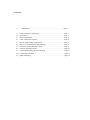
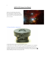
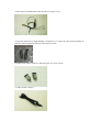
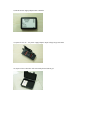
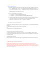
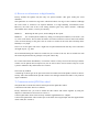
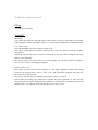
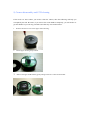
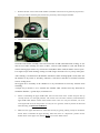
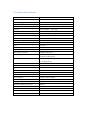
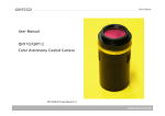
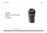
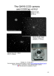
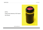
QHY-9
Mono
Cooled astronomical CCD Camera
User’s guide
QHY-9 Users guide Ver 1.0
Contents:
i)
1)
2)
3)
4)
5)
6)
7)
8)
9)
10)
11)
Introduction ………………………………………………….……Page 3
Camera Interface connections…………………………………………Page 3
Accessories…………………………………………………………….Page 5
Driver Installation……………………………………………………...Page 8
Cable connection sequence…………………………………………….Page 8
DC 201 input voltage requirement…………………………...………..Page 8
How to avoid moisture in high humidity………………………………Page 9
Connection with QHY Filter wheel…………………………………....Page 9
Software Operation Guide……………………………………………..Page 10
Camera disassembly and CCD cleaning……………………………….Page 11
Camera Specifications………………………………………………….Page 13
QHY-9 Drawings……………………………………………………….Page 14
i)
QHY9 CCD Camera User Manual
Thank you for purchasing a QHY product.
Please take the time to read the user’s guide
so you can familiarize yourself with the camera
and its functions so you can get the most out of
your new purchase.
1) Camera Interface connections
1) Filter wheel interface socket (For optional QHY filter wheel)
2) USB connector (Use USB 2.0 Cables only. If over 3 Meters in length please use a USB Hub)
3) 9-PIN connector for external power supply via QHYCCD supplied 9-pin cable and DC201
4) M42/0.75 thread mount, 3mm Depth Standard Telescope thread. When using a T ring not
supplied by QHYCCD, please check if its thread depth exceeds 3mm, as it may protrude inside the
camera and damage the shutter when longer than 3mm.
5)
6)
7)
8)
Color wheel communication LED. (Flash’s when communicating with host)
Status indication LED. (On when camera is idle)
Air socket port. M5 Europe standard (Used for Gas purging)
Air socket port. M5 Europe standard (Used for Gas purging)
2) Accessories
1) M42 (male) to M54 (male) adapter
Mounts camera to optional filter wheel
2) Optional M42 (male) to M42 (female) optic window (AR+AR or IR+AR)
Helps avoid the CCD chamber sealing glass from condensation when humidity is RH>65%
3) Special 9-pin power cable, 2.5 meter length
4) Filter wheel communication cable (Included with filter wheel)
5) Optional desiccators, in high humidity environments, it is used to dry the camera internally. It
must be used in conjunction with Air socket option 6 below.
6) Optional Air sockets, used for connecting a dry air recycle system.
7) USB 2.0 cable 1.5meter
8) DC201 Power supply adapter/TEC controller
9) Optional 12V 4A AC power supply adapter. Input voltage range 100-240V.
10) Optional Air sealed box with electrically heated silicon gel.
3) Driver Installation
1) Run the “install.bat” found in the driver folder. The driver files will then be copied into
the C:\WINDOWS\INF and the C:\WINDOWS\SYSTEM32\DRIVERS directories. If
your windows installation is not in C:\WINDOWS, then the “install.bat” file should be
modified with the correct windows location.
2) Or you may install the files manually by:
1. Copying all *.inf file into WINDOWS/INF folder
2. Copying all *.sys file into WINDOWS/SYSTEM32/DRIVERS folder
3) Connect the USB cable from camera to computer only. You do not need the 9-pin power
supply cable connected. The computer will respond with “New hardware found”.
Follow the steps shown on the screen to complete the installation.
4) Cable connection sequence
To help protect the camera from power surges or electrical spikes, we recommend the following
sequence:
1) USB cable first, 9pin power cable second, 12V supply last.
Or:
2) 9pin cable first, 12V supply, USB cable last.
Try and avoid the following methods of connection:
1) Anytime when the DC102 is powered (12V supply), avoid “Hot plugging” of the 9pin cable.
2) Connecting the USB cable while 9pin cable is connected without 12V supply on, computer may
not find the camera.
Orientation of the 9pin cable:
The 9pin cable has one end with a EMC ring. This end should be connected closest to the DC102.
5) DC201 Input voltage requirement
DC201 requires a regulated 12V input . When using an external battery, it may exceed 13V.
The high voltage may reduce the life of TEC (Thermal Electric Cooler). If forced to use an
external battery, then please avoid using Maximum cooling settings. A good setting would be at
75% to 80% cooling power.
6) How to avoid moisture in high humidity
Factory default, the QHY9 only has only one optical window (The glass sealing the CCD
chamber).
The QHY9 has an excellent 2 stage TEC which will obtain -50 deg C below ambient. Although
the CCD sensor is located in an airproof chamber, in a high humidity environments where
RH>65%, the front side of the CCD sealing chamber glass may attract moisture. Although
unavoidable due to nature, it can be prevented by:
Method 1:
Reducing the TEC power, and avoiding the dew point.
Method 2:
Use of dual optical windows by fitting a second optical window (see Section 2, sub
2), to the CCD camera. This to make the whole ccd camera contain its own air and avoid external
cooler air from dewing on the glass. The use of the Air sockets at the same time will help where
humidity is very high.
Note: Use of extra glass will cause a slight loss in optical transmission and may cause reflections
on bright objects, e.g. Stars.
We recommend storing the camera in sealed case, (See section 2 sub 10). The air sealed case with
the electrically heated silicon gel helps to keep the camera dry.
For remote stand alone installations, or when the camera is always fixed to the telescope and the
camera can’t be placed into an airproof case, the air socket can be used to connect a dry air recycle
system to maintain a dry and moisture free camera.
Note: Fast dry method.
A small bag of silicon gel can be put between the two PCB board of the QHY9 camera to achieve
fast dry. Since this method need open the camera case and upper PCB board. This is only used for
urgent conditions.
7) Connection with QHY Filter wheel
The QHY9 has a built in filter wheel control port for the QHY filter wheel.
Connection to the filter wheel is as follows.
Firstly, determine how you want to mount the filter wheel and camera together by using the
adapters as mentioned in accessories in section 2.
Connect QHY filter wheel to the telescope with the supplied M54 to 2” adapter.
Connect the QHY9 filter wheel control port to the filter wheel signal input with the supplied filter
wheel cable (See section 2).
8) Software Operation Guide
EZcap
See video for further help.
MaximDL
Installation:
Copy all the files from the “maximdl plugin” folder (From your drivers folder/CD) into the folder
of the Maximdl software (Normally found at “C:\Program Files\Diffraction Limited\MaxIm DL
V4\” for Ver. 4 etc)
Next run MaximDL, select the “Camera Control” icon.
The camera control panel will appear, and proceed to select the “QHY-9” from the available
selection list.
In SETUP option for the camera control, we will need to enter some basic settings for anti-amp
light on, Gain and Offset.
We suggest Gain of 20 and an Offset of 120 for beginner. Set “Download speed” to High for
preview, focus and Low for Imaging/Capturing.
Click “Connect” box.
The camera will then connect and be ready for use. The target temperature for the CCD cooling
can be set, for example enter -15 deg C, select “Cool”. The temperature controller will begin cool
the camera to its selected value.
Or you may enter the value for cooling by entering the cooling % required.
In this mode, the cooling is not temperature regulated, but power regulated (%). This will help
where battery life is critical and temperature regulation is not important. It controls the power load
and thus can be very efficient when lowering the power to 20% or 25 %.
9) Camera disassembly and CCD cleaning
If the need ever arises where you need to clean the camera, then the following will help you
accomplish your task. Be aware, if you remove the CCD chamber completely, you will need to re
gas the chamber to prevent any potential issues that may arise with moisture.
1.
Remove the three screws in the upper camera housing.
2.
Lift the upper housing and put aside.
3.
Remove the upper PCB board by gently lifting a little bit at a time around board.
3.
Remove the four screws of the CCD chamber (Chamber will need to be re gassed if you proceed)
If you just want to clean the glass, then do not proceed by unscrewing the chamber.
4.
Lift the CCD chamber case of the main board
Clean the CCD surface carefully. The CCD surface has an AR (Anti Reflection) coating, so care
must be used when cleaning. For dust or fibers, a blower bulb should be used, and alcohol or
similar cleaning agent with a very soft lint free cloth (Micro Fiber cloth) for hard to remove spots.
Use single sweeps while cleaning, turning over and using a clean side on every sweep of the glass.
After cleaning, re fit the front CCD chamber. If alcohol or other cleaning liquid is used, make sure
the chamber is dry before re assembly, otherwise it will freeze and show as moisture when the
CCD is cooling down.
We suggest the re assembly of the chamber in a dry environment to avoid any moisture from
remaining.
A simple way to do this is to re assemble the chamber while a heater blows dry hot/warm air
around the chamber, e.g. Hair dryer, room heater etc.
5.
When re assembling the upper PCB board, take care that each of the sockets and pins line up
correctly and sit over the right positions. The crucial one is the mini connector, located between
upper PCB board and the camera socket board. There is also two 1x2 pin connector, one is for
CCD signal and one is for temp sensor. It is easy for it to get bent, avoid any tension to the board
while inserting, and DO NOT FORCE IT.
6.
Make sure the upper PCB board is connected correctly by gently pushing evenly all around the
board. Then re assemble the upper housing. Take Note, there is a depression position for the
shutter motor in the upper case, and this MUST sit over the shutter motor.
10) Camera Specifications
CCD Type
KAF8300
Full Frame Mono CCD Sensor
Microlens on chip
Yes
Anti blooming gate
1000X
Resolution
3358 x 2536 (8.6mega pixels)
Pixel size
5.4um x 5.4um Square
Peak QE
56% @540nm
Binning mode
1x1, 2x2, 3x3, 4x4
System GAIN
0.4e-/adu(At gain=0)
Readout Noise
8e- Typical (At “Low” speed readout)
Full well
25.5ke-
ADC sample depth
16bit
CDS
YES
PGA
1X - 6X
Anti amp light
Yes
Internal Buffer
32 MByte SDRAM
Data Transfer Interface
USB2.0 High Speed
Readout Speed
800 kPixel/s (Low speed)
48% @Ha
3 MPixel/s (High speed)
Download Time (1x1 BIN)
10 sec (Low speed)
3 sec (High speed)
Mechanical shutter
Yes
Mechanical shutter latency
Approx 30ms
Temperature sensor
Internal
PWM Temperature controller
Yes
TEC
2 Stage TEC
Maxium Delta T
50 deg C below ambient
Air sockets
Two M5 Europe standard
Weight
500 grams
QHY Filter Wheel Control port
Built in
DC adapter and TEC controller
DC201
Camera mounting interface
M42/0.75mm
CCD Back focus
15mm from CCD surface to M42/0.75 screw plane
Depth 3mm MAX
11) QHY9 Drawing
See PDF file