1
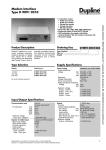
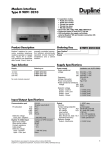
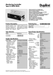
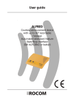
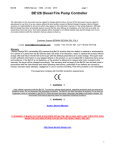
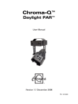
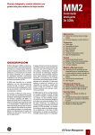
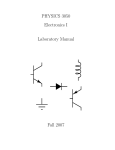
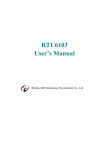
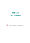
Dupline® Field- and Installationbus
Display Receiver with Limit Outputs
Type D 6369 6475
•
•
•
•
•
•
•
4-digit 7-segment LED-display with sign
Freely scaleable
2 relay limit outputs (HI, LO)
2 NPN transistor limit outputs (HIHI, LOLO)
LED-indication for all limit outputs
Automatic or manual reset of limit outputs
Protocol selectable (3 1/2-digit BCD, 4-digit BCD,
8 bit binary)
• Multiplex or normal mode
• Internal or external selection of multiplex address
• AC power supply
Product Description
Ordering Key
Freely scaleable Dupline 4
digit LED-display with sign,
for panel mounting. Readout
of analog signals, counter
Type: Dupline
Type no.
Supply
values or time. 4 limit outputs
with LED-indication. Protocol
selectable (3 1/2 digit BCD,
4-digit BCD, 8 bit binary)
D 6369 6475 024
Type Selection
Supply
Ordering no.
8/16 channels
4-digit LED
24 VAC
115/230 VAC
D 6369 6475 024
D 6369 6475 230
No code module required
Input/Output Specifications
Inputs
Limit output reset
Multiplex address selection
Open loop voltage
Short circuit current
Contact resistance
Cable length
Dielectric voltage
Inputs - Dupline
Inputs - Relay outputs
Inputs - Transistor outputs
HI, LO - limit outputs
Isolated in groups of
Contact ratings (AgCd0)
Resistive load
AC1
DC1
or
Inductive loads
AC15
DC13
Mechanical life
Electrical life (max. load)AC1
Operating frequency
Dielectric voltage
Outputs - Dupline
Outputs - transistor outputs
1 contact or NPN transistor
4 contacts or NPN transistors
5 VDC
50 µA
≤ 10 Ω
≤2m
≥ 500 VAC (rms)
≥ 4 kVAC (rms)
≥ 4 kVAC (rms)
2 SPST relays
2x1
µ (micro gap)
5 A/250 VAC (1100VA)
0.25 A/250 VDC (62 W)
5 A/25 VDC (125 W)
2.5 A/230 VAC
5 A/24 VDC
≥ 30 x 106 operations
≥ 2.5 x 10⁵ operations
≤ 7200 operations/h
≥ 4kVAC (rms)
≥ 4kVAC (rms)
Specifications are subject to change without notice (07.09.99)
Display
Display format
Display range
Display type
Height of digits
Display colour
Change of sign (automatic)
Decimal point
Scaling feature
Multiplex feature
Display test
Transmission protocol
Limit values
Settings
Channel address
Multiplex address (internal)
Scaling
Decimal point position
Limit values
Normal/multiplex mode
Enable/disable limit outputs
Transmission protocol
Internal/external selection of
multiplex address
Automatic/manual reset of
limit outputs
7-segment
-9999 to +9999 (4 digits)
LED
14.2 mm
Red
Yes
Configurable by keys
Yes
Yes
Yes
3 1/2, 4-digit BCD,
8 bit binary
4 (HIHI, HI, LO, LOLO)
Keys and display
Keys and display
Keys and display
Keys and display
Keys and display
Keys and display
Keys and display
2 DIP switches
1 DIP switch
1 DIP switch
1
D 6369 6475
Supply Specifications
Display Specifications
Power supply
Rated oprational
voltage
HIHI, LOLO limit outputs
Watchdog-output
Isolated in groups of
Output voltage range VBB
Reverse-polarity protection
Current per output
Total load capability
Short-circuit protection
Built-in protective diodes
Off-state leakage current
Output voltage drop
Dielectric voltage
Outputs-Dupline
Response time
Multiplex input
Reset inputs
Limit outputs
Watchdog output
2 NPN transistors
1 NPN transistor
1x3
6-60 VDC
None
≤ 250 mA
100%
None
None
≤ 500 µA
≤ 2.5 V
pared to the 4 limit settings,
blinking upon limit alarm,
steady state after a manual
reset. The display can be
used in normal mode as well
as in multiplex mode (3 1/2digit BCD protocol only).
When used in multiplex
mode, the multiplex address
for the display may be
selected by a selector switch
(e.g. on the cabinet door) that
connects to the "Multiplex
Address" inputs. Each of the
display values from the 16
multiplex addresses can be
scaled individually. The limit
value setting however will
always refer to the multiplex
address defined during the
configuration.
With the 4 keys at the front
the display shifts to program
mode, in which scaling,
decimal point position, limit
value settings, channel address, multiplex address etc.
is configured.
Overvoltage cat. III (IEC 60664)
230
024
Frequency
Dropout tolerance
Rated operational power
Rated operational withstand
voltage
230
024
Dielectric voltage
Supply - Dupline
Supply - Inputs
Supply - Relay outputs
Supply - Transistor outputs
115 and 230 VAC ± 15%
24 VAC ± 15%
45 to 65 Hz
≤ 4.5 ms
Typ. 8 VA
4 kV
800 V
≥ 4 kVAC (rms)
≥ 4 kVAC (rms)
≥ 4 kVAC (rms)
≥ 4 kVAC (rms)
General Specifications
Power ON delay
Indication for
HIHI limit output
HI limit output
LO limit output
LOLO limit output
Environment
Degree of protection
Pollution degree
Operating temperature
Storage temperature
Humidity (non-condensing)
Mechanical resistance
Shock
Vibration
Material
Weight
Approvals
≥ 4 kVAC (rms)
≥ 1 pulse train
≥ 1 pulse train
≥ 1 pulse train
≥ 1 pulse train
≤ 3s
LED, red
LED, yellow
LED, yelow
LED, red
IP 20
3 (IEC 60664)
0° to +60°C (+32° to +140°F)
-25° to +85°C (-13° to +185°F)
0 to 80%
15 g (11 ms)
2 g (6-55 Hz)
Glass-reinforced Noryl
460 g
UL, CSA
Mode of Operation
4-digit 7-segment LED display used to monitor analog
signals, counter values or
time of the day.
The display value is freely
scaleable within the range
-9999 to +9999 with selectable position of the decimal
point. Values from 3 1/2-digit
BCD, 4-digit BCD and 8-bit
binary transmitters can be
displayed, since the transmission protocol is selectable.
4 limit outputs are available:
HI, LO
HIHI, LOLO
2
-relay outputs
-NPN transistor outputs
Each output can be allocated
freely to any scaled display
value. The limit outputs turn
on whenever the value controlling the outputs is equal
or above the limit value
setting for HI and HIHI (equal
or below for LO and LOLO).
It is selectable whether the
limit outputs shall be reset
automatically (by the value
controlling the limit outputs
returning to normal) or
manually by activation of the
"Limit Reset" - input. The limit
outputs may also be disabled
if this feature is not required.
4 LEDs at the front also
indicate the signal level com-
For further information please
refer to the "User Manual"
delivered with the unit.
Specifications are subject to change without notice (07.09.99)
D 6369 6475
Multiplex Address Selection Inputs
Multiplex
address
Settings
Multiplex address
input terminals
MSB
0
1
2
3
4
5
6
7
8
9
a
b
c
d
e
f
0
0
0
0
0
0
0
0
1
1
1
1
1
1
1
1
LSB
0
0
0
0
1
1
1
1
0
0
0
0
1
1
1
1
0
0
1
1
0
0
1
1
0
0
1
1
0
0
1
1
0
1
0
1
0
1
0
1
0
1
0
1
0
1
0
1
DIP-switch for
function selection
Dimensions (mm)
Functional Description
Common
Watch Dog
HiHi Output
LoLo Output
Programming keys
Power Supply
Reset Input
Multiplex Input for readout
Dupline ÷
Dupline Signal
Lo Output
Hi Output
Power supply
Wiring Diagrams
Specifications are subject to change without notice (07.09.99)
3