1
Installation and Operation Manual
ETA Series
700VA to 3KVA Models
Uninterruptible Power Systems (UPS)
Part Number : _____________
Serial Number : _________________________
MAN 320 Issue 6
Page 1
ETA Series - 700VA-3KVA
INDEX
1.
1.1
1.2
1.3
1.4
1.5
GENERAL SAFETY AND OPERATIONAL INFORMATION .................. 3
General Safety ..................................................................................................... 3
Operational Performance ..................................................................................... 4
General Operating Description ............................................................................ 4
Front Panel LED Indicators................................................................................. 4
Rear Panel ........................................................................................................... 7
2.
2.1
INSTALLATION ............................................................................................... 8
Installation and Configuration ............................................................................. 8
3.
3.1
3.2
3.3
POWERING THE LOAD ................................................................................ 9
Turning ON the UPS When Mains Power is Present .......................................... 9
Turning ON the UPS from the Battery When Mains Power is Not Present ........ 9
Turning OFF the UPS .......................................................................................... 9
4.
4.1
4.2
OPERATING STATUS ................................................................................... 10
UPS Operation .................................................................................................. 10
Operating Modes: .............................................................................................. 11
4.2.1 Normal Mode .................................................................................. 11
4.2.2 By-pass Mode ................................................................................. 11
4.2.3 Battery Mode .................................................................................. 11
Error Conditions: ............................................................................................... 11
4.3.1 Overload ......................................................................................... 11
4.3.2 Mains Supply out of Tolerance ....................................................... 12
4.3.3 Over Temperature ........................................................................... 12
4.3.4 Battery Exhausted ........................................................................... 12
4.3
5.
5.1
COMMUNICATION INTERFACE .............................................................. 13
Communication Serial Port ............................................................................... 13
6.
6.1
PROBLEM SOLVING ................................................................................... 14
Common Questions ........................................................................................... 14
7.
7.1
7.2
PRODUCT SPECIFICATIONS..................................................................... 16
UPS Sizing ........................................................................................................ 16
Technical Data ................................................................................................... 17
Page 2
MAN 320 Issue 6
Installation and Operation Manual
1. GENERAL SAFETY AND OPERATIONAL INFORMATION
1.1 General Safety
Please note the following recommendations and guidelines for the safe operation of your Elite UPS.
(a) All maintenance and service functions must be performed by authorised personnel. The UPS
contains several internal power sources, which can be hazardous.
(b) The internal battery can generate an electric shock. All batteries removed from the UPS for
replacement, must be disposed of according to the current health and safety regulations. DO
NOT throw batteries into a fire: they might explode. DO NOT attempt to open the batteries:
they are sealed lead acid maintenance-free. The acid electrolyte can harm unprotected skin and
eyes.
(c) The UPS contains its own energy source (the battery). The output power sockets may be live,
even when the UPS is not connected to a power source.
(d) DO NOT operate the UPS if it is appears to be leaking battery electrolyte, or if a dry white
power residue is present on the batteries.
(e) The detachable power cable is intended to serve as a disconnection device. Make sure that the
cable connection to the rear of the UPS is easily accessible.
(f) DO NOT allow water near the UPS. DO NOT place a foreign object inside the UPS.
(g) The UPS generates approximately 1mA of leakage current. To ensure a safe maximum limit of
3.5mA, limit the total leakage current of the loads to a maximum of 2.5mA. Should the load
leakage current be over this limit, a qualified electrician should install the UPS in compliance
with IEC 309. An industrial type plug must be used for connection to the mains supply.
(h) In emergencies disconnect the power cable from the wall outlet and turn off the UPS using the
rear ON/OFF switch.
MAN 320 Issue 6
Page 3
ETA Series - 700VA-3KVA
1.2 Operational Performance
The Elite UPS incorporates the following features:
l
l
l
l
l
l
l
l
l
l
l
l
ON LINE double conversion system providing total protection to the load.
Built-in by-pass for high start up loads and UPS fault conditions.
Input power factor correction providing a sine wave input current in phase with the mains
supply.
Wide input voltage range to reduce battery operation.
Microprocessor control.
IGBT switching power devices.
Energy saving operation with extra high efficiency.
Remote control capability.
UPS monitoring and management software programmable from a standard DOS PC.
Conformity to the latest norms concerning safety and electromagnetic compatibility.
Programmable weekly turn on/turn off cycles.
Stand-by operation capability to further improve efficiency.
1.3 General Operating Description
Elite UPS are designed to provide a computer-grade, voltage and frequency stable supply to the
protected loads, under all mains conditions.
During normal operation, when mains is present and stable, the UPS provides a pure sine-wave to
the protected load. The batteries are charged and monitored by the built-in microprocessor. The
microprocessor also monitors other parameters such as mains voltage, frequency, inverter voltage
and frequency, load conditions and temperature.
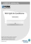
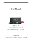
1.4 Front Panel LED Indicators
The front panel LED indicators provide a quick assessment of the UPS, load and battery status.
They indicate in which mode the UPS is working (on mains, battery or by-pass) and shows the load
and battery charge states as a percentage of the overall capacity.
Page 4
MAN 320 Issue 6
Installation and Operation Manual
OVERLOAD
100%
75%
1.
50%
25%
1.
2.
3.
4.
5.
6.
7.
8.
9.
10.
11.
12.
13.
2.
13.
12.
11.
9.
LED Bar of Load Applied
LED Bar of Battery Charge
Line Present
Battery Working
Battery Low
Replace Battery
Load on By-pass
Fault / Stand-by
Silence Push-button
Timer On
ON Push-button
UPS ON
OFF Push-button
10.
3.
4.
5.
6.
7.
8.
(1) LED Bar of Load % Used: The bar has 5 LEDs (3 green, 1 yellow & 1 red) which indicates
the power supplied by the UPS. Each lit LED corresponds to a 25% increase in load applied. The
last LED (red) lights when an overload condition occurs (i.e. at load > 100%).
(2) LED Bar of Battery Charge % Available: The bar shows the battery charge level. It has 5
green LEDs . Each lit LED represents a 20% increase in battery charge level available. If the builtin microprocessor detects a condition of battery overcharge, the complete bar blinks and the buzzer
sounds an audible alarm. The alarm will sound for 4 seconds bursts at 1 second intervals.
The Battery Charge % bar can also indicate the mains voltage available when the Alarm Silence
push-button is pressed.
Mains
LED1
>190V
LED2
>200V
LED3
>230V
MAN 320 Issue 6
LED4
>250V
LED5
>260V
Page 5
ETA Series - 700VA-3KVA
(3) MAINS PRESENT LED (green): The LED indicates that mains voltage is available and its
value is above 170V. When the UPS is switched on with mains present, the LED flashes until the
output voltage from the inverter is in phase with the mains voltage.
(4) BATTERY WORKING LED (yellow): The LED indicates that energy is being drawn from
the battery due to a power failure (mains is not available or is below 170V).
(5) BATTERY LOW LED (yellow): The LED indicates that there is approximately 2 minutes of
battery runtime available. Provided that the power management software is installed, the load will
start to shutdown open operations.
(6) REPLACE BATTERY LED (red): The LED indicates that the batteries need to be replaced.
The UPS performs a battery test every 40 hours and measures their ability to maintain the charge.
(7) LOAD ON BY-PASS LED (green): The LED indicates that power is being supplied to the
load from the mains supply.
(8) FAULT /STAND-BY LED (red): When the LED blinks, the UPS is in stand-by mode. When
lit the LED indicates that the UPS is locked to bypass. Press the OFF button to reset the lock.
(9) SILENCE PUSH-BUTTON: This button allows the user to silence the audible alarm in two
cases:
1. The UPS is in battery operation (Battery Working LED is lit).
2. The UPS is performing a countdown final procedure due to operation on low battery condition
or as part of a scheduled shutdown.
The alarm is reset, if during battery operation:
1. Mains power returns to normal
2. The remaining back-up time is almost exhausted (Low battery LED is lit)
(10) TIMER ON LED (green): Refer to the software manual.
(11) ON PUSH-BUTTON: Turns the UPS on.
(12) UPS ON LED (green): The LED indicates that power is being supplied to the load.
(13) OFF PUSH-BUTTON: Turns the UPS off. If mains is available the UPS goes into stand-by
mode. If mains is not available and the timer is not activated, the UPS remains in the "OFF" mode.
Page 6
MAN 320 Issue 6
Installation and Operation Manual
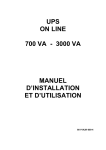
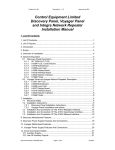
1.5 Rear Panel
8
1
3
2
1
8
4
2
5
3
4
5
7
7
6
6
1.
2.
3.
4.
5.
6.
7.
8.
Serial port with RS232 and volt-free contact pins
Dip switches
ON/OFF DC switch
Mains Fuse
Mains connection
Output sockets
Battery Extension socket
Ventilation Slot
MAN 320 Issue 6
Page 7
ETA Series - 700VA-3KVA
2. INSTALLATION
2.1 Installation and configuration
Please read carefully the following instructions before UPS installation and mains connection:
1.
2.
3.
4.
5.
6.
Place the UPS on a flat and stable surface.
Avoid placing the UPS in direct sunlight or hot air.
Keep ambient temperatures between 0ºC and 25ºC to prevent poor battery performance .
Relative room humidity must be lower than 90%.
Avoid dusty areas.
Take care to place the UPS at least 50mm away from surrounding walls and do not
cover the ventilation slots.
7. Avoid placing heavy objects on the UPS or the mains or load cables.
8. The length of the cable connecting the equipment to the UPS must not be over 10 metres.
The UPS is supplied as a 230V/50Hz UPS. However it is possible to change this setting by using the
rear panel dip switches.
220V
230V
240V
50Hz
60Hz
1200b/s
9600b/s
OFF
ON
S2
OFF
ON
S3
X
OFF
ON
OFF
Baud rate selection
Frequency selection
Voltage Selection
S3-S4 both ON or OFF
S4
X
ON
OFF
ON
S1:
S2:
S3-S4:
X:
S1
S1
S2
S3
S4
Dip-switch settings
IMPORTANT NOTE: Any modification on the dip switch setting must be carried out with the
UPS off: See section 3.3.
Page 8
MAN 320 Issue 6
Installation and Operation Manual
3. POWERING THE LOAD
3.1 Turning ON the UPS When Mains Power Is Present
1. Connect the power cable to the UPS.
2. Plug the power cable into the mains outlet.
3. Turn the rear panel switch to ON. After a few seconds the UPS turns on and the
Locked / Stand-by LED on the front panel starts blinking. The UPS is in stand-by mode:
this means that the UPS has a very low power consumption. The Microprocessor is powered
and is performing control and self-diagnostic procedures: the battery is being charged; The UPS
also works in stand-by mode during battery operation provided the timer is activated.
4. Plug the loads into the sockets on the rear of the UPS.
5. Turn on the UPS by pressing the ON button. After pressing the button, all LEDs on the
front panels light up for approximately 1 second and the UPS sounds a beep.
6. Turn on the loads connected to the UPS. After approximately 30 seconds make sure the UPS
is working properly: simulate a mains failure by unplugging the UPS power cable from the
socket. The load continues to be powered; the Battery working LED on the front panel lights
and the audible alarm sounds every 7 seconds. The UPS should return to normal operation by
reconnecting the mains cable.
3.2 Turning ON the UPS from The Battery When Mains Power Is Not Present
1. Plug the loads into the socket on the rear of the UPS.
2. Turn the rear panel switch to ON.
3. Turn on the UPS holding the ON button pressed for at least 5 seconds. After pressing the
button, all LEDs on the front panel should light up for approximately 1 second and the buzzer
sounds a beep every 7 seconds.
4. Turn on the loads connected to the UPS.
3.3 Turning OFF the UPS
(a) In Normal Operation: Hold the OFF button for at least 0.5 seconds to turn the UPS off. The
UPS switches over to stand-by operation, the Locked / Stand-by LED blinks. Turn the rear panel
switch to "OFF". If necessary remove the power cable from the mains socket.
(b) In Battery Working Mode: If the UPS is operating from battery or if the timer has been set,
hold the OFF button pressed for at least 0.5 seconds to turn the UPS off. Turn the rear panel
switch to "OFF" to prevent the UPS from starting up on battery.
NOTE 1: If the timer is activated hold the OFF button pressed for at least 5 seconds to turn the
UPS off.
NOTE 2: If you do not use your equipment over a long period, it is advisable to turn the UPS off
using the rear panel switch and to remove the power cable from the mains socket.
MAN 320 Issue 6
Page 9
ETA Series - 700VA-3KVA
4. OPERATING STATUS
4.1 UPS Operation
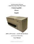
The following block diagram shows the essential components of the UPS. Please refer to this diagram
whilst reading the next sections.
By-pass
Raw
mains
Booster
EMI
input
filter
~
Inverter
=
=
~
=
~
=
=
Battery
Battery
Charger
=
Battery
Extension
UPS Block Diagram
Page 10
MAN 320 Issue 6
EMI
output
filter
Computer
Grade
Power
Installation and Operation Manual
4.2 Operating Modes
4.2.1 NORMAL Mode
In this operating mode the UPS draws power from the mains supply. The UPS output is powered by
the inverter (refer to block diagram) and batteries are charged.
4.2.2 BY PASS Mode
Bypass operation occurs under the following conditions:
(a) On UPS start-up with mains available: The UPS output is transferred to bypass and the load
is powered by the mains. This enables the UPS to cope with high in-rush currents from large loads.
During this period the microprocessor brings the inverter output in phase with the mains.
(b) Inverter Overload: The inverter will continue to supply power to the load when a temporary
overload condition occurs lasting less than 3 seconds. Over this period, the inverter automatically
protects itself and the UPS output is automatically transferred over to the bypass supply.
(c) Inverter Voltage Out Of Tolerance: Should a fault occur with the inverter section which drives
its output out of tolerance, the UPS output is automatically transferred over to the bypass supply.
(d) Inverter Failure: Should a serious fault occur with the inverter, preventing inverter operation,
the UPS output is automatically transferred over to the bypass supply.
NOTE 1: The UPS switches over to bypass operation in correspondence with the following
condition: 180Vac < Vin < 260Vac.
4.2.3 Battery Mode
Battery operation occurs when mains is not available (brown-outs or black-outs), or is below 170V.
During battery operation the buzzer sounds a beep every:
7 seconds during regularly operation.
2 seconds when the battery approaches exhaustion.
Two minutes before the battery capacity runs out the yellow BATTERY LOW LED lights up. If
the power management software is installed, the UPS initiates a controlled system shutdown.
MAN 320 Issue 6
Page 11
ETA Series - 700VA-3KVA
4.3 ERROR CONDITIONS
The UPS is designed to provide reliable automatic protection for the load. The following conditions
require immediate investigation when the UPS sounds an alarm:
4.3.1 Overload
An overload condition occurs when the protected load requires more power than the UPS is able to
supply. Under this condition the overload LED (red) on the load LED bar lights up and the alarm
sounds a constant tone.
If such an alarm condition occurs, turn off the UPS (front panel OFF button), reduce the load
applied and turn on the UPS again (front panel ON button).
4.3.2 Mains Supply Out of Tolerance
The UPS is designed to operate on a wide input voltage range. This allows the UPS to reduce
battery operation, saving it's battery charge for actual mains failures.
The microprocessor constantly checks the input voltage and frequency to guarantee operation
within a wide operating range. Outside of these limits, the UPS will not switch over to bypass mode
should an overload or UPS fault occur.
4.3.3 Over Temperature
If the internal temperature exceeds the preset values, the UPS activates its built-in protection and
locks out any function. Under this condition the Locked / stand-by LED lights up and the alarm
sounds a constant tone. Should this occur:
(a) Turn the UPS off (front panel OFF button).
(b) Disconnect the load.
Then check that:
(c) the load applied is not greater than the rating of the UPS.
(d)the ambient temperature is not over 40ºC.
(e) no heat sources are next to the UPS.
(f) the UPS is placed at least 50mm away from the surrounding walls and that the ventilation
slots not blocked.
4.3.4 Battery Exhausted
The microprocessor performs periodic battery efficiency tests. If the battery efficiency is less than
60%, the "Replace Battery" LED lights.
Page 12
MAN 320 Issue 6
Installation and Operation Manual
5. COMMUNICATION INTERFACE
5.1 Communication Serial Port
The UPS is equipped with a 9-way interface providing RS232 and volt-free contact signals.
t
Serial Port
RS 232
+ 12V ext pin 8
TX pin 3
RX pin 7
SD pin 6
INVCT pin 1
BPON pin 9
BL pin 5
BW pin 2
t
t
t
t
COM pin 4
6
7
1
2
8
3
9
4
5
D9 pin female
(a) SD shutdown signal to turn off the UPS through the PC: +(5/15)VDC for at least 3 seconds.
(b) INVCT inverter connection signal: contact is closed when the UPS output is switched over to
the inverter.
(c) BPON by-pass signal: contact is closed when the UPS output is switched over to the bypass.
(d) BL low battery signal: contact is closed 2 minutes before the back-up time is over.
(e) BW battery working signal: contact is closed when the UPS is on battery operation.
NOTE 1: Do not exceed the following limits for each contact: +30VDC / 10mA.
NOTE 2: The SHUT DOWN signal has to keep a high value for at least 3 seconds to turn off the
UPS.
NOTE3: Interface operation is possible only if there is +(10/15) DC voltage between pins 8 and 4.
MAN 320 Issue 6
Page 13
ETA Series - 700VA-3KVA
6. PROBLEM SOLVING
6.1 Common Questions
> The UPS does not switch over to stand-by operation ("Locked / Stand-by LED does not
blink, no beep is sounded)
POSSIBLE CAUSES:
1. The UPS is not properly plugged into the mains socket.
2. The socket to which it is connected does not provide mains voltage.
3. The Input fuse has blown.
4. The rear panel switch is in the OFF position.
SOLUTIONS:
1. Make sure that the plug is securely plugged into the mains socket.
2. Plug into a socket providing mains voltage.
3. Replace the input fuse with one of the same type.
4. Turn the rear panel DC switch to the ON position
> The UPS works in battery mode even if mains power is available:
POSSIBLE CAUSES:
1. Mains voltage is below 170V.
2. The Input fuse has blown.
SOLUTIONS:
1. None required. UPS operation is correct.
2. Replace the input fuse with one of the same type.
> Irregular buzzer activation:
POSSIBLE CAUSES:
1. The load oscillates around the maximum value admitted.
SOLUTIONS:
1. Reduce the load applied.
> Communication with the PC is faulty:
POSSIBLE CAUSES:
1. Incorrect baud rate.
2. The serial port chosen is already busy.
3. The interface connection is poor.
Page 14
MAN 320 Issue 6
Installation and Operation Manual
SOLUTIONS:
1. Select the proper baud rate (PC and UPS must have the same value).
2. Select a different serial port.
3. Make sure that the interface cable is not damaged and the UPS is properly connected to the
PC.
> Back-up time shorter than expected:
POSSIBLE CAUSES:
1. The Battery is not fully charged.
2. The Load is too high.
3. The Battery needs replacing.
SOLUTIONS:
1. Start a battery charging procedure lasting 8 hours (UPS in stand-by mode).
2. Reduce the load and try again.
3. Replace the battery.
MAN 320 Issue 6
Page 15
ETA Series - 700VA-3KVA
7. PRODUCT SPECIFICATIONS
7.1 UPS Sizing
Typical back-up time (in minutes) depending on the load applied (P.F. = 0.66):
LOAD (VA)
(AH)
200
300
500
700
1000
1200
1500
2000
2500
3000
700VA 700VA
(7AH) (14AH)
55
175
40
130
22
80
18
50
1KVA
(7AH)
55
40
22
18
10
1K2VA 1K5VA 1K5VA
(7AH) (7AH) (14AH)
55
60
132
40
45
88
22
27
50
18
18
28
10
13
18
8
9
16
8
2KVA
(7AH)
110
85
50
32
22
18
15
10
2K5VA
(7AH)
110
85
50
32
22
18
15
10
8
Typical power consumption figures
Type
Nominal Power in VA
Colour Monitor 14"
80
Colour Monitor 17"
100
Colour Monitor 19"/21"
150
Video Terminal
100
Colour Video Terminal 14"
150
Network Server w/o Monitor
300
Desktop 486 PC
200
Desktop Pentium PC
250
Tower 486 PC
300
Pentium Multimedia Tower PC
500
Workstation Unix
400
Matrix Printer 80 col.
70
Matrix Printer 136 col.
150
Laser Printer A3
1200
Laser Printer A4
900
IBM AS400 Model 9402
450
IBM AS400 Model 9404
650
IBM AS400 Mod. 9404 with expans
850
IBM AS400 Mod 9406 each Rack
1400
IBM advanced AS400 Mod 200
550
IBM advanced AS400 Mod 300
1100
IBM RISC 6000 Mod 320 w/o mon
350
IBM RISC 6000 Mod 520
520
IBM RISC 6000 Mod 530
550
IBM RISC 6000 Mod 540 "Power Server"
600
IBM RISC 6000 Mod 580
550
Pentium, IBM AS400, IBM RISC 6000, UNIX are registered trademarks.
Page 16
MAN 320 Issue 6
3KVA
(7AH)
120
90
55
37
27
22
17
12
10
8
Installation and Operation Manual
7.2 Technical Data
Design Topology:
Input Voltage Window:
Input Frequency Window:
Input Power Factor:
Input Current:
Output Voltage:
Output Frequency:
Output Waveform:
Overload Capability:
Crest Factor:
Bypass Voltage Range:
Bypass Frequency Range:
Front Panel Controls:
LED Indicators:
Computer and Network Interface:
SNMP Compliant:
Environmental Monitoring:
Volt-free Contacts:
RS232:
Alarm Indication:
Batteries:
Battery Recharge:
Operating Temperature:
Humidity:
Audible Noise:
Mains Connection:
Load Connection:
Design Standards:
On-line, double-conversion (with energy saving option)
170-276V (220, 230, 240V nominal)
50Hz ±5% (60Hz)
> 0.98
Sinusoidal (< 8% distortion)
230V ±1.5% (220/240V selectable)
50Hz (60Hz selectable)
Computer-grade sine-wave with less than 2% THD
200%
3:1
180-264V
±5Hz
ON, OFF and alarm silence push button
Load%, Battery Charge%, Mains present, UPS ON,
On Battery, Low Battery, Replace Battery, On Bypass,
Stand-by, Alarm Condition and UPS on Timer
1x'D' 9way
Using optional adapter on the 'D' 9way port
Using the 'D' 9way port
Mains Fail, Low Battery, UPS Alarm, EPO and Bypass
Using the 'D' 9way port
LED, audible, volt-free contacts
Sealed lead acid maintenance free
Typical recharge time 4-7hours
0-40ºC
0-90% non-condensing
< 40dBA @ 1m
2m mains lead
700VA-1K5VA 4xIEC sockets and 2KVA-3KVA 2xBS style sockets
CE and EN50091
MAN 320 Issue 6
Page 17