1
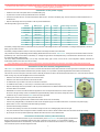
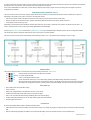
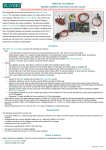
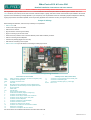
ElMod Fusion ECO & Fusion PRO
Detailed installation instructions and user manual
Before installation always read carefully all these instructions.
We congratulate on your purchase of the ElMod Fusion, the innovative and universal full-option-solution for different types of vehicles. The ElMod
Fusion enhances your model by true to scale movement, extensive weapon-, lighting- and other functions combined with simple installation. All functions
right down to the last detail may be easily adjusted on your computer by over 100 parameters which are reasonable grouped and explained in detail. By
ongoing improvements and software updates, which may be easily applied at home within few minutes, you bought a future-proof product.
Scope of delivery
Before starting the installation, check the scope of delivery for completeness.
•
ElMod Fusion PCB
•
volume control rotary knob with cable
•
cable for the RC receiver
•
plug with cable for connecting to the battery
•
plug for connecting up to two drive motors
•
shrink tube for the protection of the connection between power cable and battery connector
•
cable for connecting to the loudspeaker
•
microSD card (already plugged-in on the PCB)
•
USB cable for connecting to the computer
•
ElMod Fusion PRO only: three cables for connecting to auxiliary light sources
Connectors and operating elements
Fusion ECO and Fusion PRO
Bat
MotR
MotL
F
Sw1
Sw2
S1
L
SD
1
2
3
4
5
6
7
8
9
10
14
15
additively Fusion PRO (marked blue)
battery connector (red/black for positive and negative poles)
connector for the right motor
connector for the left motor
main fuse
DIP-switch for the configuration of the IR battle function
pushbutton for the drive setup, firmware update and reset
servo connectors
status LEDs
microSD card
turret connector (HengLong ®)
muzzle flash connector (Taigen ®, HengLong ®)
connector for IR battle functions
connector for the Tamiya ® barrel recoil mechanics
connector for the volume control rotary knob
connector for the loudspeaker
connector prepared for a WLAN-adapter
connector for the RC receiver
connectors for external motor drivers
connector for a smoke unit and extension modules
USB port for a computer
connector for a Multiplex ® M-Link® recevier
11
12
13
S2,S3
connector for the muzzle flash of the auxiliary MG
connector for rear/brake lights
connector for auxiliary light (e.g. camo light)
servo 2 & 3
Hint: all connectors are marked and described on the bottom side of the PCB.
-1-
© ElMod GbR -15-04-01
In this paragraph the installation is described step by step. It is essential that each step is accomplished correctly and completely. Wrong or improper
connection may cause malfunction or damage and/or destruction of the electronics, the installed components or the model. Please contact us if you
have further questions regarding the installation.
Connection of the power supply
•
solder the loose ends of the power cable to a suitable battery plug
•
to prevent short-circuits use the provided shrink tube for insulation
•
connect the red cable with the + terminal and the black cable with the – terminal of the battery plug. Incorrect connection causes the destruction of
the electronics
•
keep the cable length as short as possible in order to prevent interferences
The following battery types can be used:
Variant
Battery type
Cells
Voltage
undervoltage shut down
ECO/PRO
NiMh/NiCd
6
7,2 V
6V
ECO/PRO
NiMh/NiCd
7
8,4 V
7V
ECO/PRO
NiMh/NiCd
8
9,6 V
8V
PRO
NiMh/NiCd
9
10,8 V
9V
PRO
NiMh/NiCd
10
12 V
10 V
ECO/PRO
LiPo
2S
7,4 V
6,4 V
PRO
LiPo
3S
11,1 V
9,6 V
PRO
Pb
-
12V
10V
If the battery voltage drops below a certain threshold, the protective undervoltage shut down will be activated. The voltage value depends on the used
battery type as listed in the table.
If the battery voltage exceeds a maximum value, the protective overvoltage shut down will be activated.
The protective shut down (undervoltage and overvoltage) deactivates all functions of the ElMod Fusion. The engine turns off and the vehicle cannot be
operated any more. The announcement "Low Battery" or "Voltage too high" follows via loudspeaker every 5 seconds and the red status LED shows an
error state (see chapter "Status LEDs").
The factory setting is NiMh/NiCd-battery 7,2V (6 cells). If another battery type is used, it has to be set in the configuration software, otherwise the
undervoltage protection shut down won't work correctly.
If any other battery type as listed is used, a proper function cannot be guaranteed. The warranty is void if higher voltage than allowed is used!
Connection of the drive motors (integrated drivers)
The ElMod Fusion supports one or two DC motors for the main drive. Brushless motors and motors with an extra high current consumption may be used
optionally by commercially available external drivers (see next chapter). It is not possible to operate integrated and external drivers simultaneously.
The maximum current consumption of the drive motors is internally limited to 30 A peak. The allowed permanent load is 10 A. The motor drivers need no
further cooling. They are protected against short circuit and overload.
•
attach the motor wires for the right drive to the connector MotR
•
attach the motor wires for the left drive to the connector MotL
•
for vehicles with only one drive motor use one of the two connections
•
it is indifferent which cable (+/- of the motor) is connected to which screw terminal of the plug
•
keep the cable length as short as possible in order to prevent interferences! For additional interference protection
the motor cables can be twisted.
•
IMPORTANT! The motors must be interference-suppressed. This is accomplished with the use of three capacitors
as shown in the figure. Many motors are interference-suppressed already. Please check this by asking the producer
or distributor of your motors. Genuine ElMod motors are fully suppressed.
For checking the correct wiring of the motors proceed as follows:
•
make sure that the driving shaft is free to rotate and the model cannot move uncontrollably
•
connect a fully charged battery to the electronics and connect the power supply in accordance with section "connection of the power supply"
•
please wait for 3-4 sec. until the blue LED starts blinking constantly
•
press and hold the setup pushbutton
•
the motors start rotating. The motors are connected correctly if the left one is rotating slightly slower as the right
•
every few seconds the motors change their rotation. Release when the chains or wheels rotate forward. Now the motors are set up correctly.
•
By use of just one motor proceed respectively. Release the button when the motor rotates forward.
Connection of the drive motors (external drivers)
Commercially available external drivers may be connected directly to the ElMod Fusion. The operating type (internal/external
drivers) must be set by the configuration software (tab "drive", parameter "motor drivers"). It is not possible to operate
integrated and external drivers simultaneously. The external drivers are connected with the connectors 9. The black ground
wire of the drivers points to the lower edge of the PCB.
-2-
© ElMod GbR -15-04-01
Smoke generator
The smoke generator is connected to the connector for the smoke- and extension module ( connector 10). The two wires plug of
the Taigen® smoke unit is plugged as shown on the image. Therefore the plastic sprue of the smoke unit's plug must be
removed with a sharp knife. The smoke volume depends on the driving situation. The amount of the generated smoke may be
widely set up by the configuration software. The smoke function may be switched on and off by the radio freely. When using the
Taigen® smoke unit, the red and black wires may be swapped. It has no affect on the function.
Turret and weapon functions
The ElMod Fusion provides a HengLong ® compatible 8-pin turret terminal (connector 1). This connector is used by the turret
rotation motor, gun elevation motor, main gun trigger motor, front lighting and muzzle flash of the main MG.
•
an optional adapter allows the use of a Tamiya ® turret. The functions turret rotation, main gun elevation and also main lighting
and muzzle flash of the main MG are supported
•
the Taigen ® barrel recoil mechanic may be connected according to the manufacturer's manual
•
The Tamiya® barrel recoil mechanic may be attached directly to the connector 4 of the ElMod Fusion. The white wire of the plug
points to the mark left of the connector.
•
The Taigen ® XenonFlash and the HengLong ® muzzle flash LED are equipped with a 5 pin plug and may be connected to
connectior 2. The Tamiya® xenon flash is not supported.
ElMod Fusion PRO: connector 11 is scheduled for the muzzle flash of an additional MG. A LED may be connected directly
(preferably super bright, white or red). No additional parts or wiring are necessary. For details see next chapter.
Light functions
The ElMod Fusion is able to control several light channels:
• front light and MG muzzle flash on the HengLong ® turret connectior (turret and weapon functions)
•
xenon or LED muzzle flash of the main gun and muzzle flash of the MG (see chapter turret and weapon
functions)
ElMod Fusion Pro provides further light sources:
•
connector 11 for muzzle flash of the auxiliary MG (see chapter turret and weapon functions)
•
connector 12 for combined rear and brake lights. The rear light is controlled together with the front light. The
brake light is active independently of the state of the main/rear light.
•
connector 13 for auxiliary light (e.g. camo light)
Each light channel handles up to four LEDs in any color and type. The light outputs are short circuit protected, the current is limited to 30-40 mA.
The LEDs are polarity sensitive. If the LED is wrong connected it won't light up. Nevertheless due to the circuit
protection, the LEDs cannot be damaged. To light up the LED, the so-called anode must be connected with the
red wire and the cathode with the black wire (see image). If you use wired LEDs the polarity may be
distinguished as follows: the shorter wire is usually the cathode. Also the larger electrode or the flattening of the
body marks the cathode. If you use SMD-LEDs you can recognize the cathode by a little dot inside the LED or a
marking on the body.
If several LEDs are connected to one light channel, the following must be observed:
•
if the LEDs are unicolored and the same type, they have to be parallel-connected (see image)
•
if the LEDs are mixed (color and type), the LEDs of the same type are parallel-connected. These groups are series-connected then.
Sound: installation and connection
•
plug the provided volume rotary knob to connector 5
•
the ElMod Fusion PRO also provides the option to control the main volume by the radio. To activate this feature the
appropriate parameter has to be set in the configuration software (tab "sound volume", parameter "main volume
control"). In this case the volume control knob on connector 5 will be deactivated.
•
connect the loudspeaker's cable with the output of a suitable 8 Ohm loudspeaker ( connector 6). The loudspeaker's
polarity (+/-) makes no difference at this. We recommend the Visaton ® FRS7-8 (loud, high pitch) or Visaton ® FRS8-8
(quieter, lower/deeper pitch)
•
install the loudspeaker in an insulated airtight chassis with as large volume as possible.
•
check the correct fitting of the micro SD card. If the card is not well fitted or its contents is faulty, the sounds cannot be played.
•
connect a fully charged battery to the ElMod Fusion and wait 3-4 sec. until the blue LED starts blinking constantly
•
now push the setup button. The call "setup" is played.
•
if this doesn't happen, please check if the volume is set too low
-3-
© ElMod GbR -15-04-01
Servos
Depending on the type of your ElMod Fusion one servo (ElMod Fusion ECO) or three servos (ElMod Fusion PRO) may be driven.
The servos are power supplied by the board. The maximum current is 0,8 A ( ElMod Fusion ECO) or 1,5 A (ElMod Fusion PRO).
The servos are connected so that the ground line points to the upper edge of the PCB (see image).
Each servo may be assigned to one of the functions listed below. The same function may be assigned to several servos
simultaneously but every instance of this function may be configured independently (e.g. for the control of three steering axles of a
truck with different steering lock angle). For each function the servo lock angle may be reversed or limited (right and left side
separate). This is useful if the attached mechanic has a smaller movement clearance as the servo's side arm). By two other parameters each function
may be further adjusted (see table).
function
module
type
barrel recoil
ECO/PRO
effect
param 1 (0-100%)
param 2 (0-100%)
barrel recoil after firing the main gun
retraction speed
extraction speed
-
steering
ECO/PRO
steering axle
speed dependent steering
lock angle (0% - off, 100% no steering on max. speed)
elevation
PRO
horizontal movement of the main gun. The larger the stick
deflection the faster the movement
max. speed
traversion
PRO
vertical movement of the main gun. The larger the stick
deflection the faster the movement
max.speed
hatch function PRO
simulation of an open/close function. On: servo moves to the
end position. Off: servo moves to the origin position
opening speed
closing speed
radar/wiper
function
wipe function. On: servo moves between both end positions,
Off: servo moves back and remains in the starting position
speed of the "to" movement
speed of the "fro"
movement
PRO
The hatch and radar function are auxiliary functions that are activated by the special functions on the radio (see chapter "function control"). E.g. the
commander's hatch may be attached to servo 1, AA radar to servo 2 and the driver's hatch to servo 3, the functions are triggered as follows:
•
•
•
•
switch on channel 5 must be positioned to auxiliary functions
left lever to the left for activation/deactivation of the first servo's function (commander's hatch)
left lever to the top for activation/deactivation of the second servo's function (radar)
left lever to the right for activation/deactivation of the third servo's function (driver's hatch)
IR battle functions
The ElMod Fusion provides a Tamiya ® Battle Unit compatible battle function. The configuration takes place by three DIP switches. Thus it is independent
of the availability of a computer and provides full flexibility on outdoor use. The DIP switches are assigned as shown below. After the change of the
switch's position the vehicle must be powered off and on again.
Battle function deactivated. This setting should be selected, when you do not use the battle function.
Test mode activated. To check the function of the receiver you may trigger a hit by any infrared remote control.
Battle function with light vehicle active. Short reload time, but light armor.
Battle function with medium vehicle active. Moderate reload time with medium armor.
Battle function with heavy vehicle active. Long reload time, but strongest armor.
Default battle. The vehicle returns to operational state after a short time after being destroyed.
Hard core. Vehicle stays destroyed until it's switched off and on again.
-4-
© ElMod GbR -15-04-01
The selection of the vehicle's type affects its behavior during the battle. These features are listed in the following table:
Hit count
setting
Time in seconds
strong slow
down*
test mode
1
3
6
3
2
5
4x
light
1
2
3
3
15
15
1x
middle
1
4
6
5
12
15
2x
heavy
1
5
9
9
10
15
3x
destruction reload time
invulnerability
after a hit
delay until
resurrection
Mushroom blinks after
power up
slight slow
down*
* reduction of the maximum velocity of the vehicle
The ElMod Fusion indicates specific events with four sounds:
•
a fanfare after switching on with activated battle function and after each resurrection. The vehicle stays invulnerable for several seconds (see table:
reload time).
•
reloading sound. Until this sound is heard you cannot fire again.
•
metal impact after a hit. The vehicle stops and cannot be operated for two sec.
•
an explosion during vehicle's destruction. The vehicle cannot be operated for the interval shown in the table (delay until resurrection).
For the IR battle function an additional gear is required:
•
an IR sensor for the detection of a hit and signaling LEDs (sensor mushroom)
•
an IR transmitter that is preferably installed in the main gun barrel.
These components are supported in the following version:
•
the ElMod Fusion BU set is connected directly to connector 3
•
Tamiya® sensor mushroom and transmitter are connected to connector 3 by using an optional adapter
•
HengLong ®/Taigen®sensor mushroom and transmitter are connected to connector 3 by using an optional adapter
Setup of the sample set
The provided micro SD card contains several sample sets for different vehicle types
(tanks, half-tracks, ships and trucks). At delivery the sample set for a german Tiger tank
is activated. If you want to activate a different set insert the microSD in your computer
(use a suitable card reader or card adapter) and start the file "SoundManager.exe" (for
Windows®) or "SoundManager.app" (for Mac ® OSX®) located in the root folder of the
card. Follow the screen instructions.
There are two different types of sample sets available:
•
NextGen (green). These are advanced sample sets, that reproduce the different
driving conditions prototypically. These sample sets should always be preferred.
•
Legacy (grey) are sample sets that are compatible to older ElMod sound
generators. This sample sets won't exhaust the abilities of the ElMod Fusion
By the click of "confirm" the selected sample set will be activated. After quitting the
program please ensure that the card was signed out correctly. Don't remove the card
until it was signed out correctly from the system.
The SD card must not be removed or inserted in the ElMod Fusion board during operation!
RC receiver
The ElMod Fusion operates with a common radio gear. The number of required channels depend on the demands and is summarized in the table
below. The power supply of the receiver is provided by the ElMod Fusion (5V BEC, servo plug with red/black wire). An additional battery for the receiver
is not necessary.
module type channel
function
wire color
control
ECO/PRO
1
acceleration and ignition
brown
ECO/PRO
2
steering
orange
ECO/PRO
3
yellow
ECO/PRO
4
turret, weapons, light and
auxiliary functions
ECO/PRO
5
selection of the function
group
blue
3-way switch (up/off/down) or slider/knob
(reduced function when using an on/off switch)
ECO/PRO
6
user functions 1 & 2
violet
3-way switch (up/off/down)
(reduced function when using an on/off switch)
PRO
7
user functions 3 & 4
grey
3-way switch (up/off/down)
(reduced function when using an on/off switch)
PRO
8
volume control
white
slider/knob
green
-5-
stick
stick
© ElMod GbR -15-04-01
The number of connected channels is determined automatically. For the correct identification and
the correct function all mixers must be deactivated, the servo angle lock must be set to 100% and
the trimming must be centered. Please contact us if you have problems with the identification and
the operation of your radio with the ElMod Fusion. In the majority of cases the cause is detected
and fixed easily by the configuration software.
The control of channel 5 should be either a three way switch (top - center - bottom) or a
slider/knob. The switch's position determines which function group is active on the left stick (main
functions, auxiliary functions or user sounds). In case the 5 th. channel is not present, only the main
functions are available. If an on/off switch is installed, two of three function groups
are accessible. Use the configuration software to figure out which function groups
are available (tab "receiver" parameter "Function selector". see figure).
The wires carrying the receiver's signals must be plugged in on the receiver so
that the cable on the plug is connected with the signal bearing receiver's pin
(usually the upper or inner pin on the receiver, see image). The black wire of the
red/black power supply plug must be connected with the ground pin (usually the
lowest or furthest pin at the power supply connection of the receiver). If your
receiver doesn't provide polarity protected terminals, read the manual of the
receiver to find out the correct pin assignment. Wrong connected plugs won't
damage the components in most cases but the receiver won't work.
Depending on the used RC it may be necessary to change the order of the
channels or to inverse the servo travel. Please read the manual of your RC gear
for details. The signal of channels, that remains unused must not be connected.
Connection of a Multiplex ® M-Link® receiver
A Multiplex® M-Link® compatible receiver may be attached with an optional available cable to the connector 15. A detailed document can be found in our
forum (see section "In-depth informations").
Motor control (channels 1 & 2)
The ignition and acceleration/brake control is made by channel 1 (brown wire). After power up the engine doesn't run and the vehicle cannot be moved.
To start the engine the throttle control must be moved to the upper most position and hold until the ignition sequence starts (see image below). Wait until
the ignition sequence is finished and the idle sound is played. Now the vehicle is operational.
•
for moving the vehicle forward, the throttle control must be moved to the top. After engaging a gear the vehicle starts moving gently.
•
is the throttle control released or moved back to the center, the vehicle slows down (engine brake)
•
is the throttle control moved in the opposite to current direction, the vehicle brakes (actively braking)
•
the brakes are full proportional. That means, the higher the deflection in the opposite direction the stronger the brake force.
•
if the vehicle comes to a stop and the throttle control is not put back to the center, the vehicle will stand still for a moment and start moving in the
opposite direction.
•
the vehicle direction is controlled by the horizontal deflection of the right throttle stick (depending on the configuration by chains and/or steering
axles)
•
if the model stands still and the right throttle stick is moved horizontal, the vehicle fulfills a spin turn. Depending on the model type this behavior may
not be desired and can be deactivated.
•
all drive related parameters, such as maximum speed ahead and back, acceleration and deceleration power, hold time during directional change and
many more may be configured by the configuration software.
-6-
© ElMod GbR -15-04-01
To switch off the motor, proceed as follows: stop the vehicle for at least three seconds. After that the throttle stick must be put to the bottom and released
back quickly to the center position. This procedure may not last longer than one second.
Is the motor restarted after just a short time, a shorter start up sequence (warm start) is played. The time of cooling down the engine may also be
configured by the software.
Function control (channels 3 to 7)
The control of the functions of the turret, weapons, lights and the servos is done by the left throttle stick and the switch or slider/knob on channel 5.
Depending on the position of the switch on channel 5, the right stick controls
•
main functions (turret rotation, elevation and traversion of the main gun, fire the main gun and the primary MG),
•
auxiliary functions (switch on/off of the light, operation with auxiliary MG and activation of the servo's auxiliary functions),
•
or the playing of user sounds (e.g. horn).
Depending on the sample set there are different numbers and contents of user sounds. If a particular user sound is not defined, the call "User 1" to
"User 8" is played. Custom user sounds may be easily added with the Sound Manager.
Channel 6 (ElMod Fusion ECO) or channels 6 & 7 (ElMod Fusion PRO) may be assigned freely to different functions with the configuration software.
This allows quick access to frequently used functions such as light control or smoker operation.
The function layout is shown below. Short operation means holding for about 1 sec. Long operation means holding for 2 sec or longer.
* ElMod Fusion PRO only.
Status LEDs
The blue and red status LEDs on the PCB show the current operating status of the ElMod Fusion.
off
on
off
blinking no receiver signal identified
ready to operate. blue LED blinks once after stick movement
on
off
under- or overvoltage protection active
on
on
no SD card inserted, card empty or its contents faulty (operation with default settings and without sound only)
blinking red LED means that the currently played sound is clipped. That happens when the volume of several sound types
was raised in the configuration software. To fix the problem, lower these settings. Otherwise the sound may be distorted.
First start up
•
ensure that all wires are connected correctly
•
switch on the RC
•
attach a fully charged battery to the electronics and turn on the vehicle
•
the blue status LED blinks shortly after turning on and goes out again
•
after 2-3 sec. the blue LED starts blinking periodically (search for receiver signal)
•
the blue LED lights permanently as soon as valid receiver signals have been detected
•
start the engine and have fun!
Installation
By choosing the fitting position please consider the following points:
•
make sure that short circuits are excluded. The board must not touch any voltage carrying parts. Insulate all open wire connections with a shrinking
tube.
•
keep the cable length (especially the cables for the motors and the battery) as short as possible in order to prevent interferences!
-7-
© ElMod GbR -15-04-01
•
ensure that the antenna of the receiver is not located near metal parts (e.g. within a metal hull of a tank model) or between strong power consumer
(motors). This can lead to a radical disturbance of the radio signal, the malfunction of the radio signal and cause the loss of control of the model. The
ElMod Fusion provides fail-safe-mechanisms that help to detect the malfunction of the radio signal. For proper function the fail safe of the receiver
should be deactivated.
Firmware update and configuration
The freely available software for Microsoft Windows® and Mac® OSX® provides more than 100 different parameters which may be altered to get the
®
most out of your vehicle. Furthermore firmware updates of the ElMod Fusion may be transferred to the board. Please notice, that the software needs
direct access to the USB hardware and thus must be run with administrator rights when runnung on Microsoft ® Windows®. Also ensure that your malware
protection software doesn't block the USB hardware access.
Configuration and tuning
The factory settings of the ElMod Fusion matches a german 1:16 World War 2 tank with a weight of about 5 kg, metal tracks and an ElMod gear box or
a reduced metal gearbox. The settings for some other common vehicle types are provided with the configuration software. Press the button "load profile"
to choose one of them. You can also safe your own profiles by pressing the "save profile" button.
To change settings with the configuration software a connection to the ElMod
Fusion must be established. Proceed as follows:
•
power on the ElMod Fusion and connect it to the computer
•
start the configuration software with administrator rights
•
after 2-5 sec. the ElMod Fusion will be detected and the current settings are
shown on the screen.
With the configuration software various settings can be made and different
informations are displayed. The main screen is divided in four areas:
•
on the upper edge there is a tab to choose the parameter's group
•
in the center area the parameters of the current category are listed. Each
parameter has a detailed description. It is shown whenever you hoover the
mouse pointer over the parameter's name.
•
below are several buttons:
•
"Load profile" loads a previously saved or provided setting profile from your hard disk
•
"Save profile" saves all current settings on your hard disk
•
"Store" saves current settings on the ElMod Fusion. If this button is not pressed after parameters have been changed, all changes will be lost
after switching off the battery
•
•
"Help" shows a brief manual for the configuration software
•
"About" shows the version number of the software and legal notes
•
"Quit" closes the configuration software
on the bottom edge the left area shows the current connection status. The colored center area has the following meaning:
•
green: no parameter has been changed
•
yellow: settings have been changed but not saved yet on the ElMod Fusion by pressing the "Store" button. All changes will be lost after switching
off the battery.
•
red: the firmware update mode of the ElMod Fusion is active and the module is ready to receive new firmware.
Create a profile
A profile which fits perfectly to the model is extremely rare. Different battery voltage, motor types, gear boxes and types of transmission, track material
and weight are just a few examples for properties that may influence the drivability drastically. In most cases a new profile must be created for optimal
drive experience. To do so proceed as follows:
•
switch on the RC, start your model and connect it with your computer. Start the configuration program.
•
adjust the correct battery type (tab "system", parameter "battery type"). Check, if the battery is fully charged (tab "system", parameter "battery level").
If not, please charge the battery now!
•
start the engine. Adjust the parameter "Vmin" (this and all further parameters are located in the tab "drive") so that the starting sound and the motion
of the vehicle occur in the same moment. Depending on the motor type and the chassis the value is between 1 and 20.
•
•
if the model starts driving while the idle sound is still heard, raise the value.
•
if the model doesn't move although the driving sound can be already heard, reduce the value.
adjust the parameters "Vmax ahead" and "Vmax back" to the desired value. The formula for converting the speed to scaled value is : velocity of the
model (in m/s) = velocity of the prototype (in km/h): (scale x 3,6). Example: the maximum speed of a tank is 60 km/h. The model has the scale 1:16.
So the model should drive with a velocity of 60:(16x3,6) = 1,05 m/s.
•
set the shift points for the second and third gear so that they are evenly distributed (parameter: "2nd gear speed" and "3rd gear speed").
•
if necessary adjust the acceleration values until you are satisfied with the result (value for "Acceleration 3rd gear" higher as "Acceleration 2nd gear",
-8-
© ElMod GbR -15-04-01
higher as "Acceleration 1st gear").
•
adjust the speed of the spin turn (parameter "spin turn speed") so that the vehicle is well controllable. If a spin turn is not desired adjust the value 0.
•
now drive several curves with max. speed
•
if the curve radius is too high (vehicle doesn't steer strong enough), raise the value of the parameter force outer track and force inner track evenly
•
while driving out no jerk or change of the speed should be seen
•
•
if the tank is moving faster, raise the value of the parameter "Outer chain turn power"
•
if the tank is moving slower, reduce the value of the parameter "Outer chain turn power"
if your vehicle doesn't have track steering, set the parameters "Outer chain turn power" and "Inner chain turn power" to 0 and activate axle
steering (tab "Servo", parameter "Mode")
•
adjust the starting speed of the turret rotation so that the sound of the turret rotation corresponds to the turret movement (tab "Turret", parameter
"Turret min. speed")
•
adjust the max. speed of the turret rotation so that it corresponds to the prototype (tab "Turret", parameter "Turret max. speed").
•
proceed appropriately with the adjustments for elevation of the main gun (tab "Turret", parameter "Gun elevation min speed" and "Gun elevation max
speed").
•
the most important adjustments are now set. Store these changes on the ElMod Fusion (press the button "Store", see chapter "configuration and
tuning") and save the new profile on the hard drive (button "Save profile").
Reset to factory defaults
To reset all settings to factory values proceed as follows:
•
switch off the voltage and wait for 3 sec. Preventively disconnect the motors from the electronics or jack up the vehicle so that it cannot move
•
switch on the voltage again
•
as soon as the blue LED lights up (about 0.5 sec. after power on) press and hold immediately the setup pushbutton
•
the blue LED goes off. After about 4 sec the blue LED and the red LED light up
together
•
release the setup button. All parameters are set to delivery condition.
Firmware update
For updating the firmware the ElMod Fusion must be connected to a computer. To
set the PCB in update mode, switch off the voltage and press and hold the setup
pushbutton on the ElMod Fusion. Switch the voltage on again. The blue status LED
blinks three times. Now start the configuration software and press the red "Update"
button. Follow the instruction. on the screen.
The newest firmware versions are always included in the current installation
package of the configuration software. A new version of the configuration software
may be installed anytime. It's not necessary to deinstall the existing version before.
In-Depth informations
You can find several (english) documents describing various aspects of the ElMod Fusion Modules in our forum. Just enter the URL
http://www.rceifel.de/forum/showthread.php?t=8155 in your browser or go to http://www.rceifel.de → Forum → Tipps und Tricks rund um ElMod →
ElMod allgemein, posting "important informations about ElMod".
Nicht geeignet für Kinder unter 14 Jahren.
Not suitable for Children under 14 years.
Ne convient pas pour des enfants de moins de 14 ans. Niet geschikt voor kinderen onder de 14 jaar.
ElMod Thomas Kusch
Banater Str. 19
D-78054 Villingen-Schwenningen, Germany
ElMod Thomas Kusch
[email protected]
-9-
http://www.elmod.eu
© ElMod GbR -15-04-01