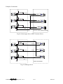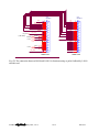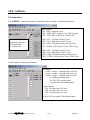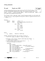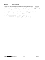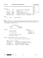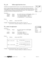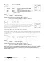
1
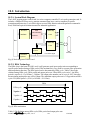
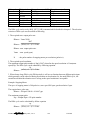
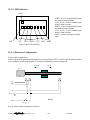
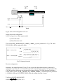
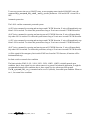
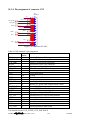
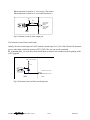
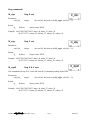
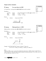
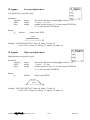
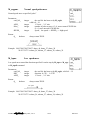
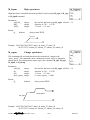
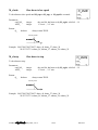
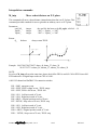
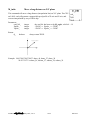
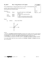
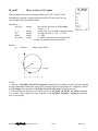
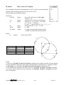
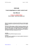
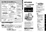
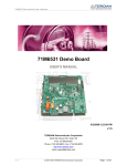
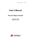
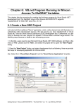
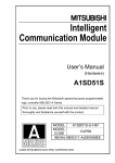
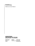
第 18 章 : 馬達運動控制
本章內容使用英文提供.
注意:
1. I-8417/8817/8437/8837 若要使用 I-8091 與 I-8090 板卡, 必須自行更換 驅動程式為 “Motion” 版
本, 標準出貨的驅動版本不支持 I-8091 與 I-8090 板卡. 請到 以下網址下載
http://www.icpdas.com/products/PAC/i-8000/isagraf-link1.htm
2. 當 I-8437/8837 更新驅動程式為“Motion” 版本時, 不支持 Ethernet 通訊. 但 Wincon-8xx7 沒有這
個限制 (Wincon-8xx7 標準出貨的驅動版本已經有支持 I-8091 與 I-8090 板卡).
3. 插在 I-8xx7 或 Wincon-8xx7 上的 I-8091 板卡, 只有 1 片 I-8091 支持 X-Y 軸連動, 其它的 I-8091
板卡只能各軸獨立運動. 另外 I-8xx7 最多只支持 2 片 I-8091 卡, Wincon 最多可支持 4 片.
18.1: Install motion driver
Restriction of the motion driver of I-8417/8817/8437/8837:
The motion driver for I-8417/8817/8437/8837 doesn’t support the Ethernet communication, however
W-8337/8737 desen’t have this limitation.
The ISaGRAF demo projects of motion for I-8417/8817/8437/8837 are “demo_27” , “demo_28”, &
“demo_46”. They are located in the
I-8000 CD-ROM: \napdos\isagraf\8000\demo\” , or at
ftp.icpdas.com/pub/cd/8000cd/napdos/isagraf/8000/demo/
The ISaGRAF demo projects of motion for W-8337/8737/8347/8747 are “wdemo_26” , “wdemo_27”,
“wdemo_28” & “wdemo_29”. They are located in the
Wincon CD-ROM: \napdos\isagraf\wincon\demo\” , or at
ftp://ftp.icpdas.com/pub/cd/wincon_isagraf/napdos/isagraf/wincon/demo/
ISaGRAF 進階使用手冊, May.2007, Ver 3.1
18-1
ICP DAS
All functions that trigger I-8091 & I-8090 are named as ”M_???” , Please refer to the On-line help from
the ISaGRAF “Help” – “Library” - “C functions” for names starting with “M_???”.
Beside, please refer to “I-8091 & I-8090 User’s Manual” .It can be found in the package box of the
i-8091, or
I-8000 CD-ROM: napdos\8000\motion\i8091\manual\
ftp site: ftp://ftp.icpdas.com/pub/cd/8000cd/napdos/8000/motion/i8091/manual/
ISaGRAF 進階使用手冊, May.2007, Ver 3.1
18-2
ICP DAS
18.2: Introduction
18.2.1: System Block Diagram
The I-8091 stepping motor control card is a micro-computer controlled, 2-axis pulse generation card. It
includes a 2Kbytes-FIFO to receive motion command from host, a micro-computer for profile
generation and protection, 2-axis DDA chip to execute DDA function when interpolation command is
used, 2500Vrms optical isolation inserted for industrial application.
CPU
2K FIFO
DDA Chip
Profile Generation
Interface
X-axis
Protection
Bus
DDA Chip
Optical
Isolation
Y-axis
Limit Switch
Input Port
Connector
Limit Switch
Limit Switch Signal
Input Port
Fig.(1) block diagram of I-8091 card
18.2.2: DDA Technology
The DDA chip is the heart of I-8091 card, it will generate equal-space pulse train corresponding to
specific pulse number during a DDA period. This mechanism is very useful to execute pulse generation
and interpolation function. The DDA period can be determined by DDA cycle. Table(1) shows the
relation among DDA cycle, DDA period and output pulse rate. When DDA cycle set to 1, the DDA
period is equal to (1+1)x1.024ms = 2.048ms. The output pulse number can be set to 0~2047, therefore
the maximum output pulse rate will be 1Mpps. The minimum output pulse rate is 3.83pps when set DDA
cycle=254 (DDA period = (254+1)x1.024ms = 261.12ms).
DDA
DDA cycle
X pulse =
Y pulse = 6
Z pulse = 4
Fig.(2) DDA mechanism
Table(1) The Relation among DDA cycle, DDA period and output pulse rate.
ISaGRAF 進階使用手冊, May.2007, Ver 3.1
18-3
ICP DAS
DDA cycle
1
2
3
.
N
.
254
DDA period
2.048ms
3.072ms
4.096ms
.
(N+1)*1.024ms
.
261.12ms
Max. pulse rate(n=2047)
999511pps
666341pps
.
.
2047/(DDA period)
.
7839pps
Min. pulse rate (n=1)
488pps
325pps
.
.
1/(DDA period)
.
3.83pps
The DDA cycle can be set by i8091_SET_VAR() command which decribed in charpter 3. The selection
criterion of DDA cycle was described as following.
1. The required max. output pulse rate.
PRmax = Vmax*N/60
2047
PRmax = ( DDAcycle + 1) * 1. 024ms
PRmax : max. output pulse rate.
Vmax : max. speed (rpm).
N
: the pulse number of stepping motor per revolution (pulse/rev).
2. The required speed resolution.
The maximum output pulse number is Np(0~2047), therefore the speed resolution is Vmax(max.
speed)/Np. The DDA cycle can be obtained by following equation.
Np
PRmax = ( DDAcycle + 1) * 1. 024ms
3. When choose large DDA cycle (DDA period), it will occur vibration between different pulse input
which generally can be observed during acceleration or deceleration. So, the small DDA cycle , the
smooth acceleration/deceleration curve as long as the speed resolution is acceptable.
Example: Stepping Motor
The spec. of stepping motor is 500 pulse/rev, max. speed 500 rpm, speed resolution 2 rpm.
The required max. pulse rate
PRmax = 500 rpm*500/60 = 4166.67 pps
The maximum output pulse
Np = 500rpm/2rpm =250 pulse number
The DDA cycle can be calculated by follow equation
Np
PRmax = ( DDAcycle + 1) * 1. 024ms
ISaGRAF 進階使用手冊, May.2007, Ver 3.1
18-4
ICP DAS
250
4166.67 = ( DDAcycle + 1) * 1. 024ms
DDA cycle = 58
High Speed = 247 pulse (4166.67*58*0.001024)
The above results means that maximum speed is 500rpm when send command i8091_SET_VAR(0, 58,
2, 2, 247) to I-8091 card.
Example: Pulse type input Servo Motor
The spec. of servo motor is 8000 pulse/rev, max. speed 3000 rpm, speed resolution 2 rpm.
The required max. pulse rate
PRmax = 3000 rpm*8000/60 = 400,000 pps
The maximum output pulse
Np = 3000rpm/2rpm =1500 pulse number
The DDA cycle can be calculated by follow equation
Np
PRmax = ( DDAcycle + 1) * 1. 024ms
1500
400,000 = ( DDAcycle + 1) * 1. 024ms
DDA cycle = 3
High Speed = 1638 pulse (400,000*4*0.001024)
The above results means that maximum speed is 3000rpm when send command i8091_SET_VAR(0, 3,
2, 2, 1638) to I-8091 card.
18.3: Hardware
18.3.1: I-8000 hardware address
The hardware address of I-8000 main system is fixed as following table. There are 4 slots I-8000 and 8
slots I-8000.
I-8000, 4 slot
address
I-8000, 8 slot
address
Slot 0 Slot 1 Slot 2 Slot 3 Slot 4
0x080 0x0A0 0x0C0 0x0E0 ---
Slot 5
---
Slot 6
---
Slot 7
---
0x080 0x0A0 0x0C0 0x0E0 0x140 0x160 0x180 0x1A0
Fig.(3) I-8000 hardware address
ISaGRAF 進階使用手冊, May.2007, Ver 3.1
18-5
ICP DAS
18.3.2: LED Indicator
power
/ORG1: X-axis’s original limit switch
for machine home position.
/LS11, /LS14 : X-axis’s negative and
positive limit switches.
/ORG2: Y-axis’s original limit switch
for machine home position.
/LS21, /LS24 : Y-axis’s negative and
positive limit switches.
/EMG : system’s emergency signal
input.
/ORG1
/LS11
/LS14 /ORG2 /LS21 /LS24 /EMG
Fig.(4) I-8091 LED indicator
18.3.3: Hardware Configuration
Limit switch configuration
Because the profile generation and protection is executed by the CPU on I-8091 card, the limit switches
must configure as following diagram. The motion command just can work properly.
CCW/BW
CW/FW
Motor
ccm
LS11 ORG1
LS14
/LS11
/ORG1
/LS14
EXT GND
X axis
/EMG
Emergency
Fig.(5) Limit switch configuration of X axis
ISaGRAF 進階使用手冊, May.2007, Ver 3.1
18-6
ICP DAS
CCW/BW
CW/FW
Motor
ccm
LS21 ORG2
LS24
/LS21
/ORG2
/LS24
EXT GND
Y axis
Fig.(6) Limit switch configuration of Y axis
Output pulse mode configuration
I-8091 card provide two kind output method.
(a) CW/CCW mode
(b) Pulse/Direction mode
The command M_s_mode(card_NO_, modeX_, modeY_) provide parameters 0: CW_CCW and 1:
PULSE_DIR to define output pulse mode.
CW
Mode = 0 (CW_CCW)
CCW
Pulse
Mode = 1 (PULSE_DIR)
Direction
Fig.(7) Output pulse mode
Direction configuration
Sometimes, the output direction of X-axis, Y-axis is not in the desired direction due to the motor’s
connection or gear train. It is recommended to unify the output direction as shown in Figure(5)(6). The
CW/FW direction is defined as toward outside from motor and the CCW/BW direction is defined as
toward inside to motor. The M_s_dir(card_NO_, defdirX_, defdirY_) command provides parameters
0: NORMAL_DIR and 1:REVERSE_DIR to define the rotating direction of motor.
Turn Servo ON/OFF (Hold ON/OFF)
ISaGRAF 進階使用手冊, May.2007, Ver 3.1
18-7
ICP DAS
To turn servo motor into servo ON(OFF) state, or turn stepping motor into hold ON(OFF) state, the
command M_s_serv(card_NO_, sonX_, sonY_) provide parameters 1:ON and 0:OFF to turn ON or
OFF.
Automatic protection
The I-8091 card has a automatic protected system.
(a) If X-aixs command is executing and moving toward CW/FW direction, X-axis will immediately stop
when LS14 is touched. To release this protection as long as X-axis move toward CCW/BW direction.
(b) If X-aixs command is executing and moving toward CCW/BW direction, X-axis will immediately
stop when LS11 is touched. To release this protection as long as X-axis move toward CW/FW direction.
(c) If Y-aixs command is executing and moving toward CW/FW direction, Y-axis will immediately stop
when LS24 is touched. To release this protection as long as Y-axis move toward CCW/BW direction.
(d) If Y-aixs command is executing and moving toward CCW/BW direction, Y-axis will immediately
stop when LS21 is touched. To release this protection, as long as Y-axis move toward CW/FW direction.
(e) If the signal of the emergency limit switch /EMG was found in CPU firmware, all motion will be
terminated and stop.
Set limit switch as normal close condition
The limit switches /EMG, /LS11, /LS14, /LS21, /LS24, /ORG1, /ORG2 is initially normal open
condition, that is, these signal is active when connect it to ground. In industrial application, it might be
recommended normal close condition, that is, these signal is active when open from ground.
The M_s_nc(card_NO_, sw_) command can be set sw=0 (default), for normal open condition. When set
sw=1, for normal close condition.
ISaGRAF 進階使用手冊, May.2007, Ver 3.1
18-8
ICP DAS
18.3.4: Pin assignment of connector CN2
CN2
DB25M-90
+5V
CW_PULSE1
CW_PULSE2
CCW_DIR1
CCW_DIR2
HOLD1
HOLD2
GND
EXT_VCC (12~24V)
ORG1
ORG2
LS11
LS21
LS14
LS24
EMG
EXT_GND
1
14
2
15
3
16
4
17
5
18
6
19
7
20
8
21
9
22
10
23
11
24
12
25
13
Fig.(8) CN2 connector of I-8091
Table of CN2 connector’s pin assignment
pin name
pin
Description
number
+5V
1
Internal +5V power, Max. output current: 50mA
CW_PULSE1
2
X-axis CW (Pulse) output pin
CCW_DIR1
3
X-axis CCW (Direction) output pin
HOLD1
4
X-axis HOLD (servo on) output pin
GND
5
Signal ground of pin 2,3,4
EXT_VCC
6
External power(12~24V) for limit switches
/ORG1
7
X-axis original (home) limit switch
/LS11
8
X-axis limit switch
9,10
No used
/LS14
11
X-axis limit switch
/EMG
12
Emergency input
EXT_GND
13
External ground for limit switch
+5V
14
Internal +5V power, Max. output current: 50mA
CW_PULSE2
15
Y-axis CW (Pulse) output pin
CCW_DIR2
16
Y-axis CCW (Direction) output pin
HOLD2
17
Y-axis HOLD (servo on) output pin
GND
18
Signal ground of pin 15,16,17
EXT_VCC
19
External power(12~24V) for limit switches
/ORG2
20
Y-axis original (home) limit switch
/LS21
21
Y-axis limit switch
22,23
No used
/LS24
24
Y-axis limit switch
EXT_GND
25
External ground for limit switch
The internal circuit of CW_PULSE, CCW_DIR, HOLD
ISaGRAF 進階使用手冊, May.2007, Ver 3.1
18-9
ICP DAS
When output these signal as 1, it can source 15mA(max.).
When output these signal as 0, it can sink 50mA(max.)
+5V
330
CW_PULSE1
CCW_DIR1
HOLD1
CW_PULSE2
CCW_DIR2
HOLD2
i8091
Fig.(9) internal circuit of pulse output pin
The internal circuit of limit switch input
Initially, the limit switch inputs of I-8091 board are normal open (N.O.), the I-8091 board will automatic
protect when limit switch pin connect to EXT_GND. The user can use the command
M_s_nc(card_NO_, 1) to let those limit switch input as normal close condition at the beginning of the
user’s program.
EXT_VCC (12V~24V)
4.7K
/ORG1, /LS11, /LS14
/ORG2, /LS21, /LS24
i8091
/EMG
Fig.(10) internal circuit of limit switch input pin
ISaGRAF 進階使用手冊, May.2007, Ver 3.1
18-10
ICP DAS
Example of connection
+5V
1
3
6
5
4
CW_PULSE1
CW +
1
4
CW -
2
3
+5V
1
3
6
5
4
CCW_DIR1
CCW +
1
4
CCW -
2
3
HOLD +
1
4
HOLD -
2
3
+5V
1
3
6
5
4
HOLD1
GND
DGND
FAN-OUT TYPE (VEXTA) DRIVER
Fig.(11) fan-out type driver (VEXTA's motor driver)
+5V
COM
1
3
6
5
4
CW_PULSE1
CW/PULSE
1
4
2
3
1
4
2
3
1
4
2
3
+5V
1
3
6
5
4
CCW_DIR1
CCW/DIR
+5V
1
3
6
5
4
HOLD1
HOLD
GND
DGND
SINK TYPE DRIVER
Fig.(12) Sink type driver
ISaGRAF 進階使用手冊, May.2007, Ver 3.1
18-11
ICP DAS
CN2
DB25M-90
S5V
CW_PULSE1
CW_PULSE2
CCW_DIR1
CCW_DIR2
HOLD1
HOLD2
SGND
EXT_VCC
EXT_VCC
(12V~24V)
PHOME1
PHOME2
PLS11
PLS21
PLS14
PLS24
PEMG
EXT_GND
CN2
DB25M-90
1
14
2
15
3
16
4
17
5
18
6
19
7
20
8
21
9
22
10
23
11
24
12
25
13
1A+
1A1B+
1B1C+
1CE5V
EGND
2A+
2A2B+
2B2C+
2CE5V
EGND
3A+
3A3B+
3B3C+
3CE5V
EGND
EGND
S8091 card
1
14
2
15
3
16
4
17
5
18
6
19
7
20
8
21
9
22
10
23
11
24
12
25
13
S8090 card
Fig.(13) The connection between I-8090 and I-8091 for function testing or pulse feedback by I-8090
encoder card.
ISaGRAF 進階使用手冊, May.2007, Ver 3.1
18-12
ICP DAS
18.4: Software
I/O connection:
The “I-8091A” connectted on the I/O connection window contains 11 digital input channels.
Input Channel:
CH1 : EMG, emergency stop
CH2 : /FFEF, FIFO is empty or not, TRUE: empty
CH3 : /FFFF, FIFO is full or not, TRUE: full
The “NO_OR_NC”
parameter can beset as
0: Normal Open
1: Normal close.
CH4 : LS11, Left limit swtch of X-axis
CH5 : LS14, Right limit swtch of X-axis
CH6 : ORG1, Original position swtch of X-axis
CH7 : XSTOP, Stop or not of X-axis, TRUE: stop
CH8 : LS21, Left limit swtch of Y-axis
CH9 : LS24, Right limit swtch of Y-axis
CH10 : ORG2, Original position swtch of Y-axis
CH11 : YSTOP, Stop or not of Y-axis, TRUE: stop
I-8090 contains 3 analog input channels.
Parameter:
x_mode : integer counting mode of X-axis
y_mode : integer counting mode of Y-axis
z_mode : integer counting mode of Z-axis
00: quadrant counting mode
10: CW/CCW counting mode
20: pulse/direction counting mode
Input Channel:
CH1 : encorder value of X-axis
CH2 : encorder value of Y-axis
CH3 : encorder value of Z-axis
CH1 to CH3 are signed 32-bit integer format
ISaGRAF 進階使用手冊, May.2007, Ver 3.1
18-13
ICP DAS
Setting commands:
M_regist
Register one I-8091
In order to distinguish more than one I-8091 card in I-8417/8817/8437/8837 platform,
the I-8091 cards should be registrated before using it. This command will assign a card
number = “card_NO_” to I-8091 card at that “address_” . If there is no I-8091 at the
given address, this command will return FALSE.
Note: If using “I_8091A” rather than “I_8091” on the I/O connection window, user don’t need to call
“m_regist” & “m_s_nc”, they are ignored. The card_NO of “I-8091A” is equal to its slot No. I-8xx7: 0 ~
7. W-8xx7: 1 ~ 7.
Parameters:
card_NO_
address_
Return:
Q_
integer
integer
boolean
valid is 0 ~ 19.
the plugged slot address of the i8091 card
slot 0: 16#80
slot 1: 16#A0
slot 2: 16#C0
slot 3: 16#E0
slot 4: 16#140
slot 5: 16#160
slot 6: 16#180
slot 7: 16#1A0
TRUE: Ok , FALSE: Fail
Example: I-8417/8817/8437/8837: demo_46, demo_27, demo_28
W-8337/8737: wdemo_26, wdemo_27, wdemo_28, wdemo_29
(* declaration: INIT as boolean <internal> and has initial value of TRUE
*)
(* TMP as boolean <internal>
*)
(* cardNO as integer <internal> and has intial value of 1
*)
(* Do some init setting at 1st scan cycle *)
if INIT then
INIT := FALSE;
TMP := M_regist(cardNO,16#80); (* plug i8091 in slot 0 *)
TMP := M_r_sys(cardNO);
(* reset i8091's setting *)
TMP := M_s_var(cardNO,4,2,5,100);
TMP := M_s_dir(cardNO,0,0);
(* Normal direction *)
TMP := M_s_mode(cardNO,1,1); (* pulse_dir mode *)
TMP := M_s_serv(cardNO,1,1);
(* X & Y server ON *)
TMP := M_s_nc(cardNO,0);
(* Normal open *)
end_if;
ISaGRAF 進階使用手冊, May.2007, Ver 3.1
18-14
ICP DAS
M_r_sys
Reset all setting
To reset I-8091 card, this command will terminate the running command in I-8091
card. User can use this command as software emergency stop. This command also
will clear all of setting, so, all I-8091 card’s parameter should be set again.
Parameters:
card_NO_
Return:
Q_
integer
the card No. has been set by M_regist, valid is 0 ~ 19
boolean
always return TRUE.
Example: I-8417/8817/8437/8837: demo_46, demo_27, demo_28
W-8337/8737: wdemo_26, wdemo_27, wdemo_28, wdemo_29
ISaGRAF 進階使用手冊, May.2007, Ver 3.1
18-15
ICP DAS
M_s_var
Set motion system parameters
To set DDA cycle, accelerating/decelerating speed, low speed and high speed value.
Parameters:
card_NO_
integer
DDA_cycle_ integer
Acc_Dec_
integer
Low_Speed_ integer
High_Speed_ integer
Return:
Q_
boolean
the card No. has been set by M_regist,
valid is 0 ~ 19
DDA cycle , valid is 1 ~ 254
Acc/Dec speed , valid is 1 ~ 200
low speed , valid is 1 ~ 200 , Low_Speed_ >= Acc_Dec_
high speed , Low_Speed_ <= High_Speed <= 2047
always return TRUE.
Note:
The lower “DDA_cycle_” is given, the smaller delay time between /ORG1 ON and /X_STOP ON (or
/ORG2 ON and /Y_STOP ON) when using M_hsporg & M_lsporg command. For ex, DDA_cycle_ set
to 4, the delay time is about 5 to 13 ms.
High_Speed
Acc_Dec
Restriction:
Acc_Dec
Low_Speed
Default value
DDA_cycle = 10
Acc_Dec = 1
Low_Speed = 10
High_Speed = 100
1 ≤ DDA _ cycle ≤ 254
1 ≤ Acc _ Dec ≤ 200
1 ≤ Low _ Speed ≤ 200
Low _ Speed ≤ High _ Speed ≤ 2047
Low_Speed >= Acc_Dec
Example: I-8417/8817/8437/8837: demo_46, demo_27, demo_28
W-8337/8737: wdemo_26, wdemo_27, wdemo_28, wdemo_29
TMP := M_s_var(1, 5, 2, 10, 150);
(* DDA_cycle = 5
--> DDA period = (5+1)*1.024ms = 6.144ms
Acc_Dec = 2
--> Acc/Dec speed = 2/(6.144ms)^2 = 52981 p/s^2
Low_Speed = 10
--> low speed = 10/6.144ms = 1628pps
High_Speed = 150 --> high speed = 150/6.144ms = 24414pps *)
ISaGRAF 進階使用手冊, May.2007, Ver 3.1
18-16
ICP DAS
M_s_dir
Define output direction of axes
Sometimes, the output direction of X-axis, Y-axis is undesired direction due to the
motor’s connection or gear train. In order to unify the output direction as shown in
Fig.(5) and Fig.(6). Where CW/FW direction is defined as toward outside from motor,
CCW/BW direction is defined as toward inside from motor. This command provide
parameters to define the rotating direction of motor.
Parameters:
card_NO_
defdirX_
defdirY_
Return:
Q_
the card No. has been set by M_regist, valid is 0 ~ 19
X axis direction definition , valid is 0 ~ 1
Y axis direction definition , valid is 0 ~ 1
0: normal direction, 1: reverse direction
integer
integer
integer
boolean
always return TRUE.
Example: I-8417/8817/8437/8837: demo_46, demo_27, demo_28
W-8337/8737: wdemo_26, wdemo_27, wdemo_28, wdemo_29
M_s_mode Set output mode
Parameters:
card_NO_
modeX_
modeY_
Return:
Q_
the card No. has been set by M_regist,
valid is 0 ~ 19
X axis mode, valid is 0 ~ 1
Y axis mode, valid is 0 ~ 1
0: CW_CCW, 1: PULSE_DIR
integer
integer
integer
boolean
always return TRUE.
CW
Mode = 0 (CW_CCW)
CCW
Pulse
Mode = 1 (PULSE_DIR)
Direction
Example: I-8417/8817/8437/8837: demo_46, demo_27, demo_28
W-8337/8737: wdemo_26, wdemo_27, wdemo_28, wdemo_29
ISaGRAF 進階使用手冊, May.2007, Ver 3.1
18-17
ICP DAS
M_s_serv
Set servo ON/OFF
Parameters:
card_NO_
integer
sonX_
sonY_
Return:
Q_
the card No. has been set by M_regist,
valid is 0 ~ 19
integer
X axis servo/hold on switch , valid is 0 ~ 1
integer
Y axis servo/hold on switch , valid is 0 ~ 1
0: OFF, 1: ON
boolean
always return TRUE.
Example: I-8417/8817/8437/8837: demo_46, demo_27, demo_28
W-8337/8737: wdemo_26, wdemo_27, wdemo_28, wdemo_29
M_s_nc
Set N.O. / N.C.
To set all of the following limit switches as N.C.(normal close) or N.O.(normall
open). If set as N.O., those limit switches are active low. If set as N.C., those limit
switches are active high. The auto-protection will automatically change the
judgement whatever it is N.O. or N.C..
Limit switches: ORG1, LS11, LS14, ORG2, LS21, LS24, EMG.
Note: If using “I_8091A” rather than “I_8091” on the I/O connection window, user don’t need to call
“m_regist” & “m_s_nc”, they are ignored. The card_NO of “I-8091A” is equal to its slot No. I-8xx7: 0 ~
7. W-8xx7: 1 ~ 7.
Parameters:
card_NO_
sw_
Return:
Q_
integer
integer
boolean
the card No. has been set by M_regist, valid is 0 ~ 19
0: N.O. (default) , 1: N.C.
always return TRUE.
Example: I-8417/8817/8437/8837: demo_46, demo_27, demo_28
W-8337/8737: wdemo_26, wdemo_27, wdemo_28, wdemo_29
Note: If using “I_8091A” in the ISaGRAF IO connection window, there is a “NO_OR_NC” parameter
can be set to define as 0:Normal Open , 1:Normal Close. So user no more need to call this “m_s_nc”
function if using “I_8091A”.
ISaGRAF 進階使用手冊, May.2007, Ver 3.1
18-18
ICP DAS
Stop commands:
M_stpx
Stop X axis
Parameters:
card_NO_
integer
Return:
Q_
boolean
the card No. has been set by M_regist, valid is 0 ~ 19
always return TRUE.
Example: I-8417/8817/8437/8837: demo_46, demo_27, demo_28
W-8337/8737: wdemo_26, wdemo_27, wdemo_28, wdemo_29
M_stpy
Stop Y axis
Parameters:
card_NO_
integer
Return:
Q_
boolean
the card No. has been set by M_regist, valid is 0 ~ 19
always return TRUE.
Example: I-8417/8817/8437/8837: demo_46, demo_27, demo_28
W-8337/8737: wdemo_26, wdemo_27, wdemo_28, wdemo_29
M_stpall
Stop X & Y axes
This command will stop X & Y axes and clear all of commands pending in the FIFO.
Parameters:
card_NO_
Return:
Q_
integer
boolean
the card No. has been set by M_regist, valid is 0 ~ 19
always return TRUE.
Example: I-8417/8817/8437/8837: demo_46, demo_27, demo_28
W-8337/8737: wdemo_26, wdemo_27, wdemo_28, wdemo_29
ISaGRAF 進階使用手冊, May.2007, Ver 3.1
18-19
ICP DAS
Simple motion commands:
M_lsporg
Low speed move to ORG
Low speed move , and stop when ORG1/ORG2 limit switch is touched.
Parameters:
card_NO_
DIR_
AXIS_
Return:
Q_
the card No. has been set by M_regist, valid is 0 ~ 19
0: CW , 1: CCW
1: X axis , 2: Y axis
integer
integer
integer
boolean
always return TRUE.
ORG
Low speed
M_hsporg
High speed move to ORG
High speed move , and stop when ORG1/ORG2 limit switch is touched.
Parameters:
card_NO_
DIR_
AXIS_
Return:
Q_
integer
integer
integer
boolean
the card No. has been set by M_regist, valid is 0 ~ 19
0: CW , 1: CCW
1: X axis , 2: Y axis
always return TRUE.
ORG
high speed
Example: I-8417/8817/8437/8837: demo_46, demo_27, demo_28
W-8337/8737: wdemo_26, wdemo_27, wdemo_28, wdemo_29
Note:
The lower “DDA_cycle_” is given, the smaller delay time between /ORG1 ON and /X_STOP ON (or
/ORG2 ON and /Y_STOP ON) when using M_hsporg & M_lsporg command. For ex, DDA_cycle_ set
to 4, the delay time is about 5 to 13 ms.
ISaGRAF 進階使用手冊, May.2007, Ver 3.1
18-20
ICP DAS
M_lsppmv
Low speed pulse move
Low speed move a specified “pulse”
Parameters:
card_NO_
AXIS_
Pulse_
Return:
Q_
the card No. has been set by M_regist, valid is 0 ~ 19
1: X axis , 2: Y axis
number of pulse to move. if > 0, move toward CW/FW dir.
if < 0, move toward CCW/BW dir.
integer
integer
integer
boolean
always return TRUE.
#pulseN
Example: I-8417/8817/8437/8837: demo_46, demo_27, demo_28
W-8337/8737: wdemo_26, wdemo_27, wdemo_28, wdemo_29
M_hsppmv
High speed pulse move
High speed move a specified “pulse”
Parameters:
card_NO_
AXIS_
Pulse_
integer
integer
integer
the card No. has been set by M_regist, valid is 0 ~ 19
1: X axis , 2: Y axis
number of pulse to move. if > 0, move toward CW/FW dir.
if < 0, move toward CCW/BW dir.
Return:
Q_
boolean
always return TRUE.
high speed
#pulseN
Example: I-8417/8817/8437/8837: demo_46, demo_27, demo_28
W-8337/8737: wdemo_26, wdemo_27, wdemo_28, wdemo_29
ISaGRAF 進階使用手冊, May.2007, Ver 3.1
18-21
ICP DAS
M_nsppmv
Normal speed pulse move
Normal speed move a specified “pulse”
Parameters:
card_NO_
AXIS_
Pulse_
SPEED_
Return:
Q_
the card No. has been set by M_regist,
valid is 0 ~ 19
integer
1: X axis , 2: Y axis
integer
number of pulse to move. if > 0, move toward CW/FW dir.
if < 0, move toward CCW/BW dir.
integer
Speed, low speed <= SPEED_ <= high speed
integer
boolean
always return TRUE.
Example: I-8417/8817/8437/8837: demo_46, demo_27, demo_28
W-8337/8737: wdemo_26, wdemo_27, wdemo_28, wdemo_29
M_lspmv
Low speed move
Low speed move toward the direction specified. It can be stop by M_stpx or M_stpy
or M_stpall command
Parameters:
card_NO_
DIR_
AXIS_
Return:
Q_
the card No. has been set by M_regist, valid is 0 ~ 19
direction. 0: CW , 1: CCW
1: X axis , 2: Y axis
integer
integer
integer
boolean
always return TRUE.
Low speed
Example: I-8417/8817/8437/8837: demo_46, demo_27, demo_28
W-8337/8737: wdemo_26, wdemo_27, wdemo_28, wdemo_29
ISaGRAF 進階使用手冊, May.2007, Ver 3.1
18-22
ICP DAS
M_hspmv
High speed move
High speed move toward the direction specified. It can be stop by M_stpx or M_stpy
or M_stpall command
Parameters:
card_NO_
DIR_
AXIS_
Return:
Q_
the card No. has been set by M_regist, valid is 0 ~ 19
direction. 0: CW , 1: CCW
1: X axis , 2: Y axis
integer
integer
integer
boolean
always return TRUE.
high speed
Example: I-8417/8817/8437/8837: demo_46, demo_27, demo_28
W-8337/8737: wdemo_26, wdemo_27, wdemo_28, wdemo_29
M_cspmv
Change speed move
This command will accelerate/decelerate the selected axis’s motor to the
“move_speed”. This command can be continuously send to I-8091 to dynamicly
change speed. The rotating motor can be stop by the command M_stpx, M_stpy,
M_stpall, or M_slwstp
Parameters:
card_NO_
dir_
axis_
move_speed_
integer
integer
integer
integer
the card No. has been set by M_regist, valid is 0 ~ 19
direction. 0: CW , 1: CCW
1: X axis , 2: Y axis
0 < move_speed_ <= 2040
Return:
Q_
boolean
always return TRUE.
move speed
Acc_Dec
Example: I-8417/8817/8437/8837: demo_46, demo_27, demo_28
W-8337/8737: wdemo_26, wdemo_27, wdemo_28, wdemo_29
ISaGRAF 進階使用手冊, May.2007, Ver 3.1
18-23
ICP DAS
M_slwdn
Slow down to low speed
To decelerate to slow speed until M_stpx or M_stpy or M_stpall is executed.
Parameters:
card_NO_
AXIS_
Return:
Q_
the card No. has been set by M_regist, valid is 0 ~ 19
1: X axis , 2: Y axis
integer
integer
boolean
always return TRUE.
SLOW_DOWN
Example: I-8417/8817/8437/8837: demo_46, demo_27, demo_28
W-8337/8737: wdemo_26, wdemo_27, wdemo_28, wdemo_29
M_slwstp
Slow down to stop
To decelerate to stop.
Parameters:
card_NO_
AXIS_
Return:
Q_
the card No. has been set by M_regist, valid is 0 ~ 19
1: X axis , 2: Y axis
integer
integer
boolean
always return TRUE.
SLOW_STOP
Example: I-8417/8817/8437/8837: demo_46, demo_27, demo_28
W-8337/8737: wdemo_26, wdemo_27, wdemo_28, wdemo_29
ISaGRAF 進階使用手冊, May.2007, Ver 3.1
18-24
ICP DAS
Interpolation commands:
M_intp
Move a short distance on X-Y plane
This command will move a short distance (interpolation short line) on X-Y plane. This
command provided a method for user to generate an arbitrary curve on X-Y plane.
Parameters:
card_NO_
Xpulse_
Ypulse_
Return:
Q_
integer
integer
integer
boolean
the card No. has been set by M_regist, valid is 0 ~ 19
-2047 <= Xpulse_ <= 2047
-2047 <= Ypulse_ <= 2047
always return TRUE.
Y
Y
10
(Xpulse,Ypulse)
9
3
4
2
X
8
5
6
7
1
X
Example: I-8417/8817/8437/8837: demo_46, demo_27, demo_28
W-8337/8737: wdemo_26, wdemo_27, wdemo_28, wdemo_29
NOTE:
For a lot of M_intp call set at the same time, please check if the FIFO is not full. Call it if FIFO is not full.
FIFO indicator is a Digital Input resides at CH3 of i-8091.
i-8091 D/I channel on ISaGRAF I/O connection window:
CH1 : EMG, emergency stop
CH2 : /FFEF, FIFO is empty or not, TRUE: empty
CH3 : /FFFF, FIFO is full or not, TRUE: full
CH4 : LS11, Left limit swtch of X-axis
CH5 : LS14, Right limit swtch of X-axis
CH6 : ORG1, Original position swtch of X-axis
CH7 : XSTOP, Stop or not of X-axis, TRUE: stop
CH8 : LS21, Left limit swtch of Y-axis
CH9 : LS24, Right limit swtch of Y-axis
CH10 : ORG2, Original position swtch of Y-axis
CH11 : YSTOP, Stop or not of Y-axis, TRUE: stop
ISaGRAF 進階使用手冊, May.2007, Ver 3.1
18-25
ICP DAS
M_intln
Move a long distance on X-Y plane
This command will move a long distance (interpolation line) on X-Y plane. The CPU
on I-8091 card will generate a trapezoidal speed profile of X-axis and Y-axis, and
execute interpolation by way of DDA chip.
Parameters:
card_NO_
Xpulse_
Ypulse_
Return:
Q_
the card No. has been set by M_regist, valid is 0 ~ 19
-524287 <= Xpulse_ <= 524287
-524287 <= Xpulse_ <= 524287
integer
integer
integer
boolean
always return TRUE.
Y
(Xpulse,Ypulse)
(0,0)
X
Example: I-8417/8817/8437/8837: demo_46, demo_27, demo_28
W-8337/8737: wdemo_26, wdemo_27, wdemo_28, wdemo_29
ISaGRAF 進階使用手冊, May.2007, Ver 3.1
18-26
ICP DAS
M_intln2
Move a long distance on X-Y plane
This command will move a long interpolation line on X-Y plane. It will automatically
generate a trapezoidal speed profile of X-axis and Y-axis by
state-machine-type calculation method.
Parameters:
card_NO_
x_, y_
speed_
acc_mode_
Return:
Q_
the card No. has been set by M_regist,
valid is 0 ~ 19
end point relate to present position
0 ~ 2040
0: enable acceleration/deceleration profile
1: disable acceleration/deceleration profile
integer
integer
integer
integer
boolean
always return TRUE.
Y
(X,Y)
(0,0)
X
NOTE:
1. Only one of M_intln2, M_intcl2 & M_intar2 command can be called at one time, the other motion
moving commands related to the same I-8091 card should not be called unless it is completed. (Please
use M_intstp to test command of M_intln2, M_intcl2 & M_intar2 completed or not).
2. One controller can only drive one I-8091 to move by M_intln2 , M_intcL2 , M_intar2 command.
Two or more I-8091 cards in the same controller to use M_intln2 , M_intcL2 , M_intar2 at the same
time is not possible.
ISaGRAF 進階使用手冊, May.2007, Ver 3.1
18-27
ICP DAS
M_intcl2
Move a circle on X-Y plane
This command will generate an interpolation circle on X-Y plane. It will
automatically generate a trapezoidal speed profile of X-axis and Y-axis by
state-machine-type calculation method.
Parameters:
card_NO_
the card No. has been set by M_regist,
valid is 0 ~ 19
integer
center point of circle relate to present position
integer
moving direction. 0: CW , 1: CCW
integer
0 ~ 2040
integer
0: enable acceleration/deceleration profile
1: disable acceleration/deceleration profile
integer
x_, y_
dir_
speed_
acc_mode_
Return:
Q_
boolean
always return TRUE.
Y
(X,Y)
CW
X
CCW
where radius = sqrt(X^2 + Y^2)
NOTE:
1. Only one of M_intln2, M_intcl2 & M_intar2 command can be called at one time, the other motion
moving commands related to the same I-8091 card should not be called unless it is completed. (Please
use M_intstp to test command of M_intln2, M_intcl2 & M_intar2 completed or not).
2. One controller can only drive one I-8091 to move by M_intln2 , M_intcL2 , M_intar2 command.
Two or more I-8091 cards in the same controller to use M_intln2 , M_intcL2 , M_intar2 at the same
time is not possible.
ISaGRAF 進階使用手冊, May.2007, Ver 3.1
18-28
ICP DAS
M_intar2
Move a arc on X-Y plane
This command will generate an interpolation arc on X-Y plane. It will automatically
generate a trapezoidal speed profile of X-axis and Y-axis by
state-machine-type calculation method.
Parameters:
card_NO_
integer
x_, y_
R_
integer
integer
dir_
speed_
acc_mode_
integer
integer
integer
Return:
Q_
boolean
the card No. has been set by M_regist,
valid is 0 ~ 19
end point of arc relate to present position
radius of arc, if > 0, the arc < 180 degree,
if < 0, the arc > 180 degree
R_ must > ( square root of (X_*X_+Y_*Y_) ) / 2
moving direction. 0: CW , 1: CCW
0 ~ 2040
0: enable acceleration/deceleration profile
1: disable acceleration/deceleration profile
always return TRUE.
'A'
CW
Y
(X,Y)
'B'
R
R>0
R>0
R<0
R<0
dir
CW
CCW
CW
CCW
path of curve
'B'
'C'
'A'
'D'
CW
'C'
CCW
'D'
X
CCW
NOTE:
1. Only one of M_intln2, M_intcl2 & M_intar2 command can be called at one time, the other motion
moving commands related to the same I-8091 card should not be called unless it is completed. (Please
use M_intstp to test command of M_intln2, M_intcl2 & M_intar2 completed or not).
2. One controller can only drive one I-8091 to move by M_intln2 , M_intcL2 , M_intar2 command.
Two or more I-8091 cards in the same controller to use M_intln2 , M_intcL2 , M_intar2 at the same
time is not possible.
ISaGRAF 進階使用手冊, May.2007, Ver 3.1
18-29
ICP DAS
M_intstp
Test X-Y plane moving command
To test the below 3 commands completed or not.
M_intln2 , M_intcL2 , M_intar2
It will return FALSE for interpolation command completed while return TRUE for busy - not completed
yet.
Return:
Q_
boolean
TRUE: busy , FALSE: completed
NOTE:
1. Only one of M_intln2, M_intcl2 & M_intar2 command can be called at one time, the other motion
moving commands related to the same I-8091 card should not be called unless it is completed. (Please
use M_intstp to test command of M_intln2, M_intcl2 & M_intar2 completed or not).
2. One controller can only drive one I-8091 to move by M_intln2 , M_intcL2 , M_intar2 command.
Two or more I-8091 cards in the same controller to use M_intln2 , M_intcL2 , M_intar2 at the same
time is not possible.
ISaGRAF 進階使用手冊, May.2007, Ver 3.1
18-30
ICP DAS
I-8090 encorder commands:
M_r_enco
Reset I-8090’s encorder value to 0
Parameters:
slot_ integer
axis_ integer
the slot No. where the i8090 is plugged, 0 ~ 7
1: x-axis, 2: y-axis, 3: z-axis
Return:
Q_
always return TRUE.
boolean
Example: demo_27, demo_28, demo_46
ISaGRAF 進階使用手冊, May.2007, Ver 3.1
18-31
ICP DAS