1
Day/ Night Color Camera
USER’S MANUAL
Version 2.0.0
1
Thank you for purchasing our product. If there is any question or request, please do not hesitate to contact dealer.
This manual is applicable to DS-2CC102/112/192P(N)(-A), DS-CC502/512P(N)(-A), DS-2CC592P(N),
DS-2CC532P(N), DS-2CC102/112/192P(N)-MM, DS-2CC132P(N), DS-2CC511/591P(N)-A,
DS-2CC502/512/592P(N)-FB, DS-2CC502/512 P(N)-FD1/FD2 Day / Night Color Camera.
This manual may contain several technically incorrect places or printing errors, and the content is subject to
change without notice. The updates will be added into the new version of this manual. We will readily improve or
update the products or procedures described in the manual.
2
Safety Instructions
These instructions are intended to ensure that user can use the product correctly to avoid danger or property loss.
The precaution measure is divided into “Warnings” and “Cautions”
Warnings: Serious injury or death may cause if any of the warnings is neglected.
Cautions: Injury or equipment damage may cause if any of the cautions is neglected.
Warnings Follow these safeguards
Cautions Follow these precautions
to prevent serious injury or
to prevent potential injury or
death.
material damage.
Warnings
1.
In the use of the product, you must be strict compliance with the electrical safety regulations of the nation and
region.
2.
Input voltage should meet both the SELV(Safety Extra Low Voltage) and the Limited Power Source with AC
24V or DC 12V according to the IEC60950-1 standard. Please refer to technical specifications for detail
information.
3.
Do not connect several devices to one power adapter as adapter overload may cause over-heat or fire hazard.
4. Please make sure that the plug is firmly connected on the power socket.
5.
When the product is mounted on wall or ceiling, the device shall be firmly fixed.
6.
If smoke, odor or noise rise from the device, turn off the power at once and unplug the power cable, and then
please contact the service center.
7.
If the product does not work properly, please contact your dealer or the nearest service center. Never attempt to
disassemble the camera yourself. (We shall not assume any responsibility for problems caused by
unauthorized repair or maintenance.)
3
Cautions:
1.
Make sure the power supply voltage is correct before using the camera.
2.
Do not drop the camera or subject it to physical shock.
3.
Do not touch CCD (Charge Coupled Device) modules with fingers. If cleaning is necessary, use clean cloth
with a bit of ethanol and wipe it gently. If the camera will not be used for an extended period, please turn on
the lens cap to protect the CCD from dirt.
4.
Do not aim the camera at the sun or extra bright places. A blooming or smear may occur otherwise (which is
not a malfunction however), and affecting the endurance of CCD at the same time.
5.
The CCD may be burned out by a laser beam, so when any laser equipment is on using, make sure that the
surface of CCD will not be exposed to the laser beam.
6.
Do not place the camera in extremely hot, cold(the operating temperature shall be-10℃~+60℃ ), dusty
or damp locations, and do not expose it to high electromagnetism radiation.
7.
To avoid heat accumulation, good ventilation is required for operating environment.
8.
Keep the camera away from liquid while on using.
9.
While on a delivery, the camera shall be packed in its original packing, or packing of the same texture.
10.
Regular part replacement: a few parts (e.g. electrolytic capacitor) of the equipment shall be replaced
regularly according to their average enduring time. The average time varies because of differences between
operating environment and using history, so regular checking is recommended for all the users. Please
contact with your dealer for more details.
4
Table of Contents
CHAPTER 1 INTRODUCTION ............................................................................................................... 1
1.1 FEATURES ........................................................................................................................................... 1
1.2 FUNCTIONS ........................................................................................................................................ 1
1.3 DESCRIPTION OF BOX CAMERA ............................................................................................................... 2
1.3.1 Side Panel of Box Camera ........................................................................................................ 2
1.3.2 Rear Panel of Box Camera ....................................................................................................... 3
1.3.3 Description of Dome Camera................................................................................................... 5
CHAPTER 2 INSTALLATION .................................................................................................................. 6
2.1 BOX CAMERA MOUNTING ..................................................................................................................... 6
2.2 DOME CAMERA MOUNTING .................................................................................................................. 7
APPENDIX ........................................................................................................................................ 10
DAY/NIGHT COLOR BOX CAMERA ............................................................................................................... 10
Specifications.................................................................................................................................. 10
Dimensions ..................................................................................................................................... 10
DAY/NIGHT MINI COLOR BOX CAMERA ....................................................................................................... 11
Specifications.................................................................................................................................. 11
Dimensions ..................................................................................................................................... 11
DAY/NIGHT CMOS-BASED COLOR BOX CAMERA........................................................................................... 12
Specifications.................................................................................................................................. 12
Dimensions ..................................................................................................................................... 12
DAY/NIGHT COLOR DOME CAMERA ............................................................................................................ 13
Specifications.................................................................................................................................. 13
Dimensions ..................................................................................................................................... 13
DAY & NIGHT VARI-FOCAL COLOR DOME CAMERA ........................................................................................ 14
Specifications.................................................................................................................................. 14
Dimensions ..................................................................................................................................... 14
DAY & NIGHT VANDAL-PROOF COLOR DOME CAMERA ................................................................................... 15
Specifications.................................................................................................................................. 15
Dimensions ..................................................................................................................................... 15
DAY & NIGHT COMS-BASED COLOR DOME CAMERA ..................................................................................... 16
Specifications.................................................................................................................................. 16
Dimensions ..................................................................................................................................... 16
UFO COLOR CAMERA .............................................................................................................................. 17
Specifications.................................................................................................................................. 17
Dimensions ..................................................................................................................................... 17
5
Chapter 1 Introduction
1.1 Features
Adopting high performance CCD and CMOS advanced print circuit board design technology, the camera features
high resolution, low distortion, low noise, etc., and thus is extremely applicable to the surveillance system and
image processing system. It provides the following features:
• High performance image sensor CCD, high resolution, capable of providing clear images.
• Low illumination, color/B&W auto switch.
• Backlight compensation
• Auto white balance
• High SNR provides clear and pleased image.
• Auto electronic shutter control, adaptive to different environments.
• Auto gain control, with brightness adaptive.
• Advanced technique design, with high reliability.
1.2 Functions
ICR Switch: The camera provides two operation modes: color, and B&W. You can increase sensitivity in low light
conditions by switching to B&W mode (removing the IR cut filter). Color mode is preferred in normal lighting
conditions.
AGC: AGC allows users to adjust the gain of amplifier, enabling the camera to output the standard video signal in
different lighting conditions. As scene lighting decreases, the system will automatically adjust, adding a mixture of
AGC and slow shutter according to the AGC limit setting. In low illumination, AGC will increase camera’s
sensitivity, and output bright and clear video.
S/N ratio: It refers to the ratio between signal voltage and noise voltage. While the ratio is larger, the effect of
noise is less, and the image is more spotless.
White Balance: This feature automatically processes the viewed image to retain color balance over a color
temperature range.
.
1
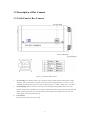
1.3 Description of Box Camera
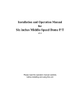
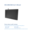
1.3.1 Side Panel of Box Camera
Figure 1.1 Side Panel of Box Camera
1.
Iris Lens Plug: The camera provides an iris lens plug in negative pattern with four square holes, and the
definition of pins is shown above. The plug of video drive auto iris adopts three pins, i.e. Power +, Video,
and GND; while the interface of DC drive auto iris adopts four pins, i.e. Damp+, Damp-, Drive+ and Drive-.
2.
Focus Adjusting: When it still fails to realize precise focusing after having confirmed the correct lens
interface, the back focus adjustment may be required. Operate the following steps: tighten the lens firstly and
then loosen the fixed back focus ring; rotate the lens slowly until the video image turns to be clear, and
finally tighten and lock the back focus ring.
3.
Lens Interface:
The lens interface adopts CS connector type.
2
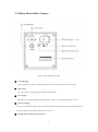
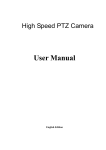
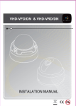
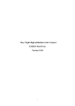
1.3.2 Rear Panel of Box Camera
Figure 1.2 Rear Panel of Box Camera
①
Level Adjusting:
The level adjusting is valid for iris adjusting in DC drive mode, while invalid for video drive mode.
②
Video output:
The video output is in 1Vp-p Composite Output (75-ohm /BNC).
③
Power supply:
During the power supply, make sure the input voltage is 12VDC +10%, ranging from 10.8V to 13.2V.
④
Auto Iris Selecting:
Auto iris lens of both video and DC drive modes can be adopted for this camera. Please select DD mode for DC
drive auto iris lens or VD mode for video drive auto iris lens.
⑤
SW Dial Switch Settings are listed as below:
3
NAGC
Normal AGC: Normal automatic gain control. The gain is about 30dB with this function
turned on.
SAGC
Super AGC: Super automatic gain control. The gain is about 60dB with this function turned
on.
FL
BLC
AI
AES
SHARP
SOFT
Use it to avoid the spot caused by different circuit power.
Backlight Compensation: Automatically adjust exposure value for backlight compensation.
Auto Iris: Turn the switch to AI to enable auto iris.
Auto Electronic Shutter: Turn the switch to AES for non-auto-iris mode.
Turn on the SHARP function to obtain sharper edge for images.
Turn on the SOFT function to obtain softer edge for images.
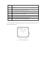
Note: The rear panel varies according to different models. E.g., the rear panel of DS-2CC132P(N) as shown
below is different from Figure1.2.
Figure 1.3 DS-2CC132P(N) Rear Panel
4
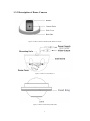
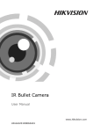
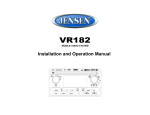
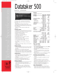
1.3.3 Description of Dome Camera
Bubble
Camera Drive
Side Cover
Back Box
Figure 1.4 DS-2CC502/512/592P(N)(-FB) DS-2CC532P(N)
Figure 1.5 DS-2CC511/591P(N)-A
Figure 1.6 DS-2CC502/512P(N)-FD1/FD2
5
Chapter 2 Installation
Prior to mounting, please make sure that the device in the package is in good condition and all the assembly parts
are complete.
2.1 Box Camera Mounting
Note: The lens must be the CS assembly type with the weight less than 1kg. The outshoot part behind the
mounting surface must be less than 5mm. Please adopt C-type adapter for C assembly lens mounting.
Two mounting methods are selectable for box camera: wall mounting and in-ceiling mounting. The dome camera
generally adopts the in-ceiling mounting. Please refer to the following steps (take the in-ceiling mounting for
example, and the wall mounting steps keep the same).
1.
Select the mounting mode and mount the corresponding camera bracket. For cement wall application, the
expansion screws must be installed firstly (the mounting holes of the expansion screws should align with
those in the mounting bracket), and then install the mounting bracket, as shown as figure 2.1. For wood wall
application, directly use the self-tapping screws to install the mounting bracket to the wall. Please note that
the mounting wall must be capable of supporting three times the sum weight of camera and mounting
bracket.
2.
Install the camera. Use the mounting base on top of camera to screw the camera into the mounting bracket.
Figure 2.1 Install the Camera
3.
Adjust the camera to the desired monitoring location, and then tighten the screws on the mounting bracket to
secure the camera in position.
4.
Install the lens into the camera, and fasten the lens after having adjusted the focus.
6
Figure 2.2 Install the Lens
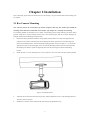
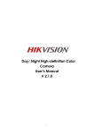
2.2 Dome Camera Mounting
The following section has described the DS-2CC511/591P(N)-A series dome camera installation as the example.
Note: the mounting wall must be with certain thickness and capable of supporting three times the weight of
dome camera.
1.
Use your hands to hold the back box of dome camera and then rotate the bubble in anti-clockwise
direction to remove it.
Figure 2.3 Remove the Bubble
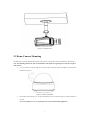
2.
By referring to the Figure 2.2.2, use the self-tapping screws to secure the back box of dome camera to
the wall.
Note: the expansion screws are required for the cement wall mounting application.
7
Figure 2.4 Secure Back Box to the Wall
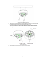
3.
Adjust the lens to the desired monitoring location and obtain the clear images. This series dome camera
has the pan movement range of 0~355°and the tilt movement range of 0~90°.
Note: Loosen the fixed screws on the lens before adjusting it; and after adjustment, tighten the
screws again.
Figure 2.5 Adjust Lens
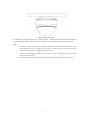
4.
Rotate the bubble in clockwise direction to replace it to the dome camera.
8
Figure 2.6 Replace the Bubble
The installation of DS-CC502/512P(N)(-A),
DS-2CC592P(N), DS-2CC502/512/592P(N)-FB, DS-2CD502/512
P(N)-FD1 /FD2 and DS-2CC532P(N) series dome camera keep the same with the instructions described above.
Note:
1.
The bubble of DS-CC502/512P(N)(-A), DS-2CC592P(N) and DS-2CC502/512/592P(N)-FB series
dome camera has two layers. Remove the outer layer by rotating it in anti-clockwise direction and
remove the internal layer by rotating in clockwise direction.
2.
Apply the hex screwdriver (provided) to loosen the screws on the vandal-proof enclosure for the
vandal-proof dome camera.
3.
Unscrew the fixed ring before installing the DS-2CD502/512P(N)-FD1/FD2 series dome camera.
9
Appendix
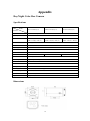
Day/Night Color Box Camera
Specifications
Model
Parameter
DS-2CC102P(N)(-A)
DS-2CC112P(N)(-A)
DS-2CC192P(N)(-A)
Image Sensor
1/3 inch SONY Super HAD CCD
Signal System
PAL / NTSC
Effective Pixels
PAL: 500 (H) × 582 (V)
PAL: 752 (H) × 582 (V)
PAL: 752 (H) × 582 (V)
NTSC: 510 (H) × 492 (V)
NTSC: 768 (H) × 494 (V)
NTSC: 768 (H) × 494 (V)
Min. Illumination
0.1Lux @ F1.2
Electronic Shutter
1/50 (1/60)s to 1/100,000s
Day & Night
Electronic
Auto Iris Lens
DC / Video
Lens Mount
C / CS mount
Horizontal Resolution
420 TVL
Synchronization
Internal synchronization
Video Output
1Vpp Composite Output
S/N Ratio
More than 48 dB
BLC
ON / OFF
Working Temperature
-10℃ ~ 60℃
Power Supply
12VDC, ±10%, “-A” series support12VDC / 24V AC, ±10%.
Power Consumption
2W MAX ("-A" series 3.5MAX)
Dimension (mm)
63 × 59 × 114(2.5” × 2.34”×4.52”)
Weight
550g (1.2lbs)
480TVL
Dimensions
10
540TVL
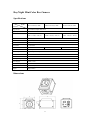
Day/Night Mini Color Box Camera
Specifications
Model
Parameter
DS-2CC102P (N) -MM
DS-2CC112P (N) -MM
DS-2CC192P (N) -MM
Image Sensor
1/3 inch SONY Super HAD CCD
Signal System
PAL / NTSC
Effective Pixels
PAL: 500 (H) × 582 (V)
PAL: 752 (H) × 582 (V)
PAL: 752 (H) × 582 (V)
NTSC: 510 (H) × 492 (V)
NTSC: 768 (H) × 494 (V)
NTSC: 768 (H) × 494 (V)
Min. Illumination
0.1Lux @ F1.2
Electronic Shutter
1/50 (1/60) s to 1/100,000s
Auto Iris Lens
DC / Video
Lens Mount
C / CS mount
Horizontal Resolution
420 TVL
Synchronization
Internal synchronization
Video Output
1Vpp Composite Output
S/N Ratio
More than 48 dB
BLC
ON / OFF
Working Temperature
-10℃ ~ 60℃
Power Supply
12VDC, ±10%
Power Consumption
1.5W MAX
Dimension (mm)
48 × 52 × 70(1.9” ×2.05”×2.76”)
Weight
400g (0.88lbs)
480TVL
Dimensions
11
540TVL
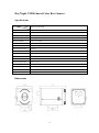
Day/Night CMOS-based Color Box Camera
Specifications
Parameter
Model
DS-2CC132P/132N
Image Sensor
1/4 inch CMOS
Signal System
PAL / NTSC
Effective Pixels
640 (H) × 480 (V)
Min. Illumination
0.1Lux @ F1.2
Electronic Shutter
1/25 s to 1/15,000 s
Auto Iris Lens
----
Lens Mount
C / CS
mount
Horizontal Resolution
480TVL
Synchronization
Internal Synchronization
Video Output
1Vp-p Composite Output (75Ω/BNC)
S/N Ratio
More than 48dB
BLC
ON / OFF
Working Temperature
-10℃ ~ 60℃
Power Supply
12V DC, ±10%
Power Consumption
2W MAX
Dimension (mm)
63 × 59 × 114(2.5” × 2.34”×4.52”)
Weight
550g (1.2lbs)
Dimensions
12
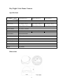
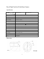
Day/Night Color Dome Camera
Specifications
Parameter
Model
DS-2CC502P (N)(-A)
DS-2CC512P (N)(-A)
DS-2CC592P (N)
Image Sensor
1/3 inch SONY Super HAD CCD
Signal System
PAL / NTSC
Effective Pixels
PAL: 500 (H) × 582 (V)
PAL: 752 (H) × 582 (V)
PAL: 752 (H) × 582 (V)
NTSC: 510 (H) × 492 (V)
NTSC: 768(H) × 494 (V)
NTSC: 768 (H) × 494 (V)
Min. Illumination
0.1Lux @ F1.2
Electronic Shutter
1/50 (1/60)s to 1/100,000s
Lens
3.6mm @ F2.0 (2.8mm, 6mm, 8mm, 12mm, 16mm optional)
Horizontal Resolution
420 TVL
Synchronization
Internal Synchronization
Video Output
1Vp-p Composite Output (75Ω / BNC)
S/N Ratio
More than 48 dB
BLC
ON
Working Temperature
-10℃ ~ 60℃
Power Supply
12VDC, ±10% , (-A) Support 24VAC / 12VDC
Power Consumption
2W MAX
Dimension (mm)
Φ138 x 87 (Φ5.5” x 3.45”)
Weight
380g (0.83lbs
480TVL
Dimensions
13
540TVL
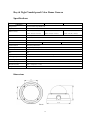
Day & Night Vari-focal Color Dome Camera
Specifications
Parameter
Model
DS-2CC511P (N)-A
DS-2CC591P (N)-A
Image Sensor
1/3 inch SONY Super HAD CCD
Signal System
PAL / NTSC
Effective Pixels
PAL: 752 (H) × 582 (V)
Min. Illumination
0.1Lux @ F1.2
Electronic Shutter
1/50 (60)s to 1/100,000s
Lens
3.5~9mm Auto Iris Lens (2.8-11mm auto iris lens optional)
Pan Rotation
0°~355°
Tilt Rotation
0°- 90°
Horizontal Resolution
480 TVL
Synchronization
Internal Synchronization
Video Output
1Vp-p Composite Output (75Ω / BNC)
S/N Ratio
More than 48 dB
White Balance
Auto
BLC
ON/OFF
Working Temperature
-10℃~60℃
Power Supply
24VAC / 12VDC, ±10%
Power Consumption
3.5W MAX
Dimension (mm)
φ124 × 109.1(φ 4.9” ×4.3” )
Weight
400g(0.88lbs)
NTSC: 768 (H) × 494 (V)
540TVL
Dimensions
14
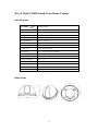
Day & Night Vandal-proof Color Dome Camera
Specifications
Parameter
Model
DS-2CC502P (N)-FB
DS-2CC512P (N)-FB
Image Sensor
1/3 inch SONY Super HAD CCD
Signal System
PAL / NTSC
Effective Pixels
DS-2CC592P (N)-FB
PAL: 500 (H) × 582 (V)
PAL: 752 (H) × 582 (V)
PAL: 752 (H) × 582 (V)
NTSC: 510 (H) × 492 (V)
NTSC: 768 (H) × 494 (V)
NTSC: 768 (H) × 494 (V)
Min. Illumination
0.1Lux @ F1.2
Electronic Shutter
1/50 (1/60)s to 1/100,000s
Lens
3.5 ~ 8mm (4 ~ 9mm optional)
Horizontal Resolution
420TVL
Synchronization
Internal Synchronization
Video Output
1Vp-p Composite Output (75Ω/BNC)
S/N Ratio
More than 48dB
BLC
ON
Impact Protection
IEC60068-275 test, Eh, 50J; EN50102, exceeding IK10.
Working Temperature
-10℃ ~ 60℃
Power Supply
12VDC, ±10%
Power Consumption
2W MAX
Dimensions (mm)
φ140 × 92 (φ5.55” × 3.65”)
Weight
660g (1.45lbs)
480TVL
Dimensions
15
540TVL
Day & Night COMS-based Color Dome Camera
Specifications
Parameter
Model
DS-2CC532P/N
Image Sensor
1/4 inch CMOS
Signal System
PAL / NTSC
Effective Pixels
640 (H) × 480 (V)
Min. Illumination
0.1Lux @ F1.2
Electronic Shutter
1/25s to 1/15,000s
Lens
3.6mm @ F2.0 (6mm, 8mm, 12mm, 16mm optional)
Horizontal Resolution
480TVL
Synchronization
Internal Synchronization
Video Output
1Vp-p Composite Output (75Ω/BNC)
S/N Ratio
More than 48dB
BLC
ON
Working Temperature
-10℃ ~ 60℃
Power Supply
12V DC, ±10%
Power
2W MAX
Consumption
Dimension (mm)
Φ110 × 62 (Φ4.36” × 2.46”)
Weight
330g (0.72lbs)
Dimensions
16
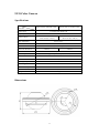
UFO Color Camera
Specifications
Model
Parameter
DS-2CC502P / 502N-FD1 / FD2
DS-2CC512P / 512N-FD1 / FD2
Image Sensor
1/3"SONY Super HAD CCD
Signal System
PAL / NTSC
Effective Pixels
PAL:500 (H) × 582 (V)
PAL:752 (H) × 582 (V)
NTSC:510 (H) × 492( V)
NTSC:768 (H) × 494 (V)
Min. Illumination
0.1Lux @ F1.2
Electronic Shutter
1/50 (1/60s ~ 1/100,000s
Lens
Horizontal Resolution
3.6mm (6mm,8mm optional)
420TVL
Synchronization
Video Output
480TVL
Internal Synchronization
1Vp-p Composite Output (75Ω/BNC)
S/N Ratio
More than 48dB
BLC
ON
-10℃ ~ 60℃
Working Temperature
Power Supply
DC12±10%
Power Consumption
1.5W MAX
Dimensions (mm)
φ54
Weight
240g
Dimensions
17