1
Machine Automation Controller
CJ-series
Analog I/O Units
Operation Manual
for NJ-series CPU Unit
CJ1W-AD0@@-@@
CJ1W-DA0@@@
CJ1W-MAD42
Analog I/O Units
W490-E1-03
OMRON, 2011
All rights reserved. No part of this publication may be reproduced, stored in a retrieval system, or transmitted, in any form, or
by any means, mechanical, electronic, photocopying, recording, or otherwise, without the prior written permission of
OMRON.
No patent liability is assumed with respect to the use of the information contained herein. Moreover, because OMRON is
constantly striving to improve its high-quality products, the information contained in this manual is subject to change without
notice. Every precaution has been taken in the preparation of this manual. Nevertheless, OMRON assumes no responsibility
for errors or omissions. Neither is any liability assumed for damages resulting from the use of the information contained in
this publication.
Introduction
Introduction
Thank you for purchasing an CJ-series Analog I/O Unit.
This manual contains information that is necessary to use with the NJ-series CPU Unit. Please read
this manual and make sure you understand the functionality and performance of the NJ-series CPU
Unit before you attempt to use it in a control system.
Keep this manual in a safe place where it will be available for reference during operation.
Intended Audience
This manual is intended for the following personnel, who must also have knowledge of electrical systems (an electrical engineer or the equivalent).
• Personnel in charge of introducing FA systems.
• Personnel in charge of designing FA systems.
• Personnel in charge of installing and maintaining FA systems.
• Personnel in charge of managing FA systems and facilities.
For programming, this manual is intended for personnel who understand the programming language
specifications in international standard IEC 61131-3 or Japanese standard JIS B3503.
Applicable Products
This manual covers the following products.
• CJ-series Analog I/O Units
• CJ1W-AD041-V1/081-V1/042
• CJ1W-DA021/041/08V/08C/042V
• CJ1W-MAD42
CJ-series Analog I/O Units Operation Manual for NJ-series CPU Unit(W490)
1
Relevant Manuals
Relevant Manuals
There are three manuals that provide basic information on the NJ-series CPU Units: the NJ-series CPU
Unit Hardware User’s Manual, the NJ-series CPU Unit Software User’s Manual, and the NJ-series
Instructions Reference Manual.
Most operations are performed from the Sysmac Studio Automation Software. Refer to the Sysmac
Studio Version 1 Operation Manual (Cat. No. W504) for information on the Sysmac Studio.
Other manuals are necessary for specific system configurations and applications.
Read all of the manuals that are relevant to your system configuration and application to make the most
of the NJ-series CPU Unit.
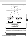
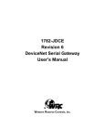
NJ-series User’s Manuals
CJ-series Special Unit Operation
Manuals for NJ-series CPU Unit
NJ-series Troubleshooting Manual
NJ-series CPU Unit Built-in
EtherNet/IP Port User´s Manual
NJ-series Motion Control
Instructions Reference Manual
NJ-series CPU Unit Built-in
EtherCAT Port User´s Manual
NJ-series CPU Unit Motion
Control User´s Manual
NJ-series Instructions
Reference Manual
NJ-series CPU Unit
Software User´s Manual
NJ-series CPU Unit
Hardware User´s Manual
Basic information
Introduction to NJ-series Controllers
Setting devices and hardware
Using motion control
Using EtherCAT
Using EtherNet/IP
Using CJ-series Units
Software settings
Using motion control
Using EtherCAT
Using EtherNet/IP
Programming
Using motion control
Using EtherCAT
Using CJ-series Units
Programming error processing
Testing operation and debugging
Using motion control
Using EtherCAT
Using EtherNet/IP
Troubleshooting and managing
errors in an NJ-series Controller
Use the
relevant
manuals for
references
according to
any error that
occurs.
Maintenance
Using EtherCAT
Using EtherNet/IP
Using CJ-series Units
2
CJ-series Analog I/O Units Operation Manual for NJ-series CPU Unit(W490)
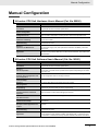
Manual Configuration
Manual Configuration
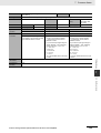
NJ-series CPU Unit Hardware User’s Manual (Cat. No. W500)
Section
Description
Section 1
Introduction
This section provides an introduction to the NJ-series Controllers and their features,
and gives the NJ-series Controller specifications.
Section 2
System Configuration
This section describes the system configuration used for NJ-series Controllers.
Section 3
Configuration Units
This section describes the parts and functions of the configuration devices in the NJseries Controller configuration, including the CPU Unit and Configuration Units.
Section 4
Installation and Wiring
This section describes where and how to install the CPU Unit and Configuration Units
and how to wire them.
Section 5
Troubleshooting
This section describes the event codes, error confirmation methods, and corrections
for errors that can occur.
Section 6
Inspection and Maintenance
This section describes the contents of periodic inspections, the service life of the Battery and Power Supply Units, and replacement methods for the Battery and Power
Supply Units.
Appendices
The appendices provide the specifications of the Basic I/O Units, Unit dimensions,
load short-circuit protection detection, line disconnection detection, and measures for
EMC Directives.
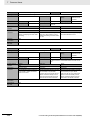
NJ-series CPU Unit Software User’s Manual (Cat. No. W501)
Section
Description
Section 1
Introduction
This section provides an introduction to the NJ-series Controllers and their features,
and gives the NJ-series Controller specifications.
Section 2
CPU Unit Operation
This section provides information that is necessary to use the CPU Unit, including
how the CPU Unit works and the operations that it performs depending on the status
of the CPU Unit.
Section 3
I/O Ports, Slave Configuration, and
Unit Configuration
This section describes how to use I/O ports, how to create the slave configuration
and unit configuration and how to assign functions.
Section 4
Controller Setup
This section describes the initial settings of the function modules.
Section 5
Designing Tasks
This section describes the task system and types of tasks.
Section 6
Programming
This section describes programming, including the programming languages and the
variables and instructions that are used in programming.
Section 7
Checking Operation and Actual
Operation
This section describes the items and procedures for checking the operation of an NJseries Controller, including offline debugging procedures.
Section 8
CPU Unit Functions
This section describes the functionality provided by the CPU Unit.
Section 9
Communications Setup
This section describes how to go online with the CPU Unit and how to connect to
other devices.
Section 10
Example of Actual Application Procedures
This section describes the procedures that are used to actually operate an NJ-series
Controller.
Section 11
Troubleshooting
This section describes the event codes, error confirmation methods, and corrections
for errors that can occur.
Appendices
The appendices provide the CPU Unit specifications, task execution times, specifications of individual system-defined variables, data attribute lists, CJ-series Unit memory information, CJ-series Unit memory allocation methods, and version information.
CJ-series Analog I/O Units Operation Manual for NJ-series CPU Unit(W490)
3
Manual Configuration
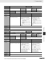
Sysmac Studio Version 1 Operation Manual (Cat. No. W504)
Section
Description
Section 1
Introduction
This section provides an overview and lists the specifications of the Sysmac Studio
and describes its features and components.
Section 2
Installation and Uninstallation
This section describes how to install and uninstall the Sysmac Studio.
Section 3
System Design
This section describes the basic concepts for designing an NJ-series System with the
Sysmac Studio and the basic operating procedures.
Section 4
Programming
This section describes how to create programs with the Sysmac Studio.
Section 5
Online Connections to a Controller
This section describes how to go online with a Controller.
Section 6
Debugging
This section describes how to debug the programs online on the Controller or debug
it offline with the Simulator.
Section 7
Other Functions
This section describes other functions that are supported by the Sysmac Studio,
including security functions and troubleshooting functions.
Section 8
Reusing Programming
This section describes how to reuse the programs that you create with the Sysmac
Studio.
Section 9
Support Software Provided with the
Sysmac Studio
This section describes the Support Software that is provided with the Sysmac Studio.
Section 10
Troubleshooting
This section describes the error messages that are displayed when you check a program on the Sysmac Studio and how to correct those errors.
Appendices
The appendices describe the following:
Driver Installation for Direct USB Cable Connection
Specifying One of Multiple Ethernet Interface Cards
Online Help
Simulation Instructions
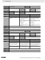
CJ-series Analog I/O Units Operation Manual for NJ-series CPU Unit
(Cat. No. W490) (This Manual)
Section
4
Description
Section 1
System Design
This section provides a brief description of the features and the functionality of the
Analog I/O Units and describes where and how to install the Units.
Section 2
CJ-series Analog Input Units
(CJ1W-AD041-V1/081-V1)
This section provides the specifications of the CJ1W-AD041-V1/081-V1 Analog Input
Units, and describes how to wire and use the Units.
Section 3
CJ-series Analog Input Units
(CJ1W-AD042)
This section provides the specifications of the CJ1W-AD042 Analog Input Units, and
describes how to wire and use the Units.
Section 4
CJ-series Analog Output Unit
(CJ1W-DA021/041/08V/08C)
This section provides the specifications of the CJ1W-DA021/041/08V/08C Analog
Output Units, and describes how to wire and use the Units.
Section 5
CJ-series Analog Output Unit
(CJ1W-DA042V)
This section provides the specifications of the CJ1W-DA042V Analog Output Units,
and describes how to wire and use the Units.
Section 6
CJ-series Analog I/O Unit
(CJ1W-MAD42)
This section provides the specifications of the CJ1W-MAD42 Analog I/O Units, and
describes how to wire and use the Units.
Section 7
Common Items
This chapter explains the operating procedure common among Analog Input Units,
Output Units and I/O Units.
Appendices
---
CJ-series Analog I/O Units Operation Manual for NJ-series CPU Unit(W490)
Manual Configuration
CS/CJ-series Analog I/O Units Operation Manual (Cat. No. W345)
Section
Description
Section 1
System Design
This section provides a brief description of the features and the functionality of the
Analog I/O Units and describes where and how to install the Units.
Section 2
CS-series Analog Input Units
(CS1W-AD041-V1/081-V1/161)
This section provides the specifications of the CS1W-AD041-V1/081-V1/161 Analog
Input Units, and describes how to wire and use the Units.
Section 3
CJ-series Analog Input Units
(CJ1W-AD041-V1/081-V1)
This section provides the specifications of the CJ1W-AD041-V1/081-V1 Analog Input
Units, and describes how to wire and use the Units.
Section 4
CJ-series Analog Input Units
(CJ1W-AD042)
This section provides the specifications of the CJ1W-AD042 Analog Input Units, and
describes how to wire and use the Units.
Section 5
CS-series Analog Output Units
(CS1W-DA041/08V/08C)
This section provides the specifications of the CS1W-DA041/08V/08C Analog Output
Units, and describes how to wire and use the Units.
Section 6
CJ-series Analog Output Unit
(CJ1W-DA051/041/08V/08C)
This section provides the specifications of the CJ1W-DA051/041/08V/08C Analog
Output Units, and describes how to wire and use the Units.
Section 7
CJ-series Analog Output Unit
(CJ1W-DA042V)
This section provides the specifications of the CJ1W-DA042V Analog Output Units,
and describes how to wire and use the Units.
Section 8
CS-series Analog I/O Unit
(CS1W-MAD44)
This section provides the specifications of the CS1W-MAD44 Analog I/O Units, and
describes how to wire and use the Units.
Section 9
CJ-series Analog I/O Unit
(CJ1W-MAD42)
This section provides the specifications of the CJ1W-MAD42 Analog I/O Units, and
describes how to wire and use the Units.
Appendices
---
CJ-series Analog I/O Units Operation Manual for NJ-series CPU Unit(W490)
5
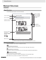
Manual Structure
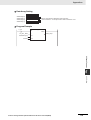
Manual Structure
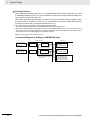
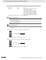
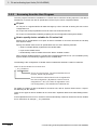
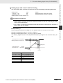
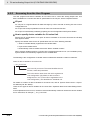
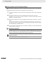
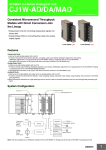
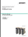
Page Structure
The following page structure is used in this manual.
Mounting Units
Level 1 heading
Level 2 heading
Level 3 heading
Connecting Controller Components
Gives the current
headings.
4 Installation and Wiring
Level 2 heading
4-3
Level 3 heading
4-3-1
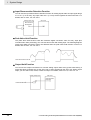
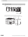
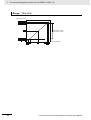
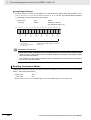
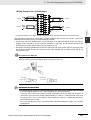
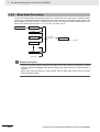
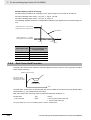
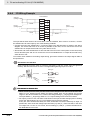
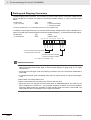
The Units that make up an NJ-series Controller can be connected simply by pressing the Units together
and locking the sliders by moving them toward the back of the Units. The End Cover is connected in the
same way to the Unit on the far right side of the Controller.
A step in a procedure
1
Join the Units so that the connectors fit exactly.
Hook
Indicates a procedure.
Hook holes
Connector
4-3 Mounting Units
4
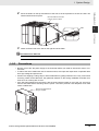
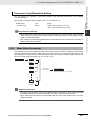
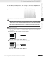
The yellow sliders at the top and bottom of each Unit lock the Units together. Move the sliders
toward the back of the Units as shown below until they click into place.
Move the sliders toward the back
until they lock into place.
Lock
Release
Slider
Gives the number
of the main section.
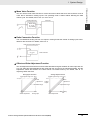
Precautions for Correct Use
Special information
The sliders on the tops and bottoms of the Powe r Supply Unit, CPU Unit, I/O Units, Special I/O
Units, and CPU Bus Units must be completely locked (until they click into place) after connecting
the adjacent Unit connectors.
Icons indicate
precautions, additional
information, or reference
information.
Manual name
4-3-1 Connecting Controller Components
2
Page tab
NJ-series CPU Unit Hardware User’s Manual (W500)
4-9
This illustration is provided only as a sample. It may not literally appear in this manual.
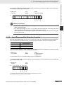
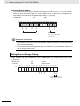
Special Information
Special information in this manual is classified as follows:
Precautions for Safe Use
Precautions on what to do and what not to do to ensure safe usage of the product.
Precautions for Correct Use
Precautions on what to do and what not to do to ensure proper operation and performance.
Additional Information
Additional information to read as required.
This information is provided to increase understanding or make operation easier.
Note References are provided to more detailed or related information.
6
CJ-series Analog I/O Units Operation Manual for NJ-series CPU Unit(W490)
Manual Structure
Precaution on Terminology
In this manual, “download” refers to transferring data from the Sysmac Studio to the physical Controller
and “upload” refers to transferring data from the physical Controller to the Sysmac Studio.
For the Sysmac Studio, synchronization is used to both upload and download data. Here, “synchronize”
means to automatically compare the data for the Sysmac Studio on the computer with the data in the
physical Controller and transfer the data in the direction that is specified by the user.
CJ-series Analog I/O Units Operation Manual for NJ-series CPU Unit(W490)
7
Manual Structure
8
CJ-series Analog I/O Units Operation Manual for NJ-series CPU Unit(W490)
Sections in this Manual
Sections in this Manual
1
2
1
System Design
3
2
CJ-series Analog Input Units
(CJ1W-AD041-V1/081-V1)
4
3
CJ-series Analog Input Units
(CJ1W-AD042)
5
4
CJ-series Analog Output Unit
(CJ1W-DA021/041/08V/08C)
6
5
CJ-series Analog Output Unit
(CJ1W-DA042V)
7
A
6
CJ-series Analog I/O Unit
(CJ1W-MAD42)
I
7
Common Items
A
Appendices
I
Index
CJ-series Analog I/O Units Operation Manual for NJ-series CPU Unit(W490)
9
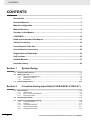
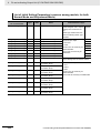
CONTENTS
CONTENTS
Introduction ............................................................................................................... 1
Relevant Manuals ...................................................................................................... 2
Manual Configuration ............................................................................................... 3
Manual Structure ....................................................................................................... 6
Sections in this Manual ............................................................................................ 9
CONTENTS............................................................................................................... 10
Read and Understand this Manual ........................................................................ 15
Safety Precautions .................................................................................................. 18
Precautions for Safe Use........................................................................................ 23
Precautions for Correct Use................................................................................... 29
Regulations and Standards.................................................................................... 32
Unit Versions ........................................................................................................... 35
Related Manuals ...................................................................................................... 37
Revision History ...................................................................................................... 38
Section 1
1-1
1-2
System Design
Features and Functions .......................................................................................................... 1-2
Mouting the Unit ...................................................................................................................... 1-7
1-2-1
1-2-2
1-2-3
1-3
Function Applications ........................................................................................................... 1-10
Section 2
2-1
CJ-series Analog Input Units (CJ1W-AD041-V1/081-V1)
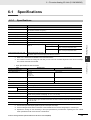
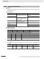
Specifications .......................................................................................................................... 2-2
2-1-1
2-1-2
2-1-3
2-2
2-3
Specifications .............................................................................................................................. 2-2
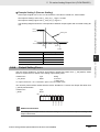
Input Function Block Diagram ..................................................................................................... 2-4
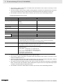
Input Specifications ..................................................................................................................... 2-4
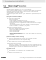
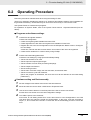
Operating Procedure ............................................................................................................... 2-7
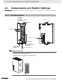
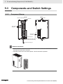
Components and Switch Settings.......................................................................................... 2-9
2-3-1
2-3-2
2-3-3
2-3-4
2-3-5
10
Basic System Configuration ........................................................................................................ 1-7
Mounting Procedure.................................................................................................................... 1-8
Precautions ................................................................................................................................. 1-9
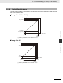
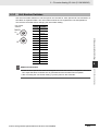
Component Names ..................................................................................................................... 2-9
Indicators................................................................................................................................... 2-10
Unit Number Switches............................................................................................................... 2-11
Operating Mode Switch............................................................................................................. 2-11
Voltage/Current Switch.............................................................................................................. 2-12
CJ-series Analog I/O Units Operation Manual for NJ-series CPU Unit(W490)
CONTENTS
2-4
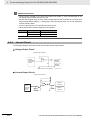
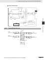
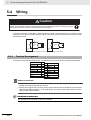
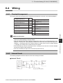
Wiring ..................................................................................................................................... 2-13
2-4-1
2-4-2
2-4-3
2-4-4
2-4-5
2-5
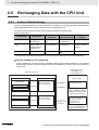
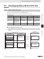
Exchanging Data with the CPU Unit .................................................................................... 2-18
2-5-1
2-5-2
2-5-3
2-6
Outline of Data Exchange......................................................................................................... 2-18
Accessing from the User Program............................................................................................ 2-19
Allocating Device Variable for CJ-series Unit............................................................................ 2-20
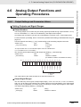
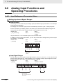
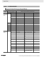
Analog Input Functions and Operating Procedures .......................................................... 2-25
2-6-1
2-6-2
2-6-3
2-6-4
Section 3
3-1
Terminal Arrangement .............................................................................................................. 2-13
Internal Circuit .......................................................................................................................... 2-14
Voltage Input Disconnection ..................................................................................................... 2-15
Input Wiring Example ............................................................................................................... 2-16
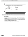
Input Wiring Considerations ..................................................................................................... 2-17
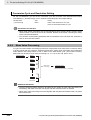
Input Settings and Conversion Values ...................................................................................... 2-25
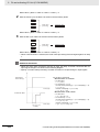
Mean Value Processing ............................................................................................................ 2-27
Peak Value Hold Function......................................................................................................... 2-31
Input Disconnection Detection Function ................................................................................... 2-32
CJ-series Analog Input Units (CJ1W-AD042)
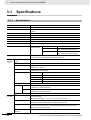
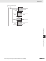
Specifications .......................................................................................................................... 3-2
3-1-1
3-1-2
3-1-3
Specifications.............................................................................................................................. 3-2
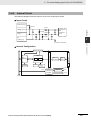
Input Function Block Diagram..................................................................................................... 3-3
Inputs Specifications................................................................................................................... 3-3
3-2
Operating Procedure ............................................................................................................... 3-6
3-3
Components and Switch Settings ......................................................................................... 3-8
3-3-1
3-3-2
3-3-3
3-4
Wiring ..................................................................................................................................... 3-10
3-4-1
3-4-2
3-4-3
3-4-4
3-4-5
3-5
Section 4
Input Settings and Conversion Values ...................................................................................... 3-20
Mean Value Processing ............................................................................................................ 3-22
Input Scaling Function .............................................................................................................. 3-24
Peak Value Hold Function......................................................................................................... 3-26
Input Disconnection Detection Function ................................................................................... 3-27
CJ-series Analog Output Unit
(CJ1W-DA021/041/08V/08C)
Specifications .......................................................................................................................... 4-2
4-1-1
4-1-2
4-1-3
4-2
Outline of Data Exchange......................................................................................................... 3-15
Accessing from the User Program............................................................................................ 3-16
Allocating Device Variable for CJ-series Unit............................................................................ 3-17
Analog Input Functions and Operating Procedures .......................................................... 3-20
3-6-1
3-6-2
3-6-3
3-6-4
3-6-5
4-1
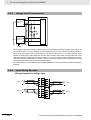
Terminal Arrangement .............................................................................................................. 3-10
Internal Circuit .......................................................................................................................... 3-11
Voltage Input Disconnection ..................................................................................................... 3-12
Input Wiring Example ............................................................................................................... 3-12
Input Wiring Considerations ..................................................................................................... 3-14
Exchanging Data with the CPU Unit .................................................................................... 3-15
3-5-1
3-5-2
3-5-3
3-6
Component Names..................................................................................................................... 3-8
Indicators .................................................................................................................................... 3-9
Unit Number Switches ................................................................................................................ 3-9
Specifications.............................................................................................................................. 4-2
Output Function Block Diagram.................................................................................................. 4-3
Output Specifications.................................................................................................................. 4-4
Operating Procedure ............................................................................................................... 4-6
4-2-1
4-2-2
CJ1W-DA021/041 ....................................................................................................................... 4-6
CJ1W-DA08V/08C ...................................................................................................................... 4-8
CJ-series Analog I/O Units Operation Manual for NJ-series CPU Unit(W490)
11
CONTENTS
4-3
Components and Switch Settings........................................................................................ 4-10
4-3-1
4-3-2
4-3-3
4-3-4
4-4
Wiring ..................................................................................................................................... 4-13
4-4-1
4-4-2
4-4-3
4-4-4
4-5
Section 5
5-3
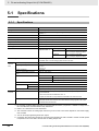
Specifications .......................................................................................................................... 5-2
Components and Switch Settings.......................................................................................... 5-8
Section 6
12
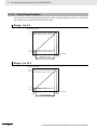
Output Settings and Conversion Values.................................................................................... 5-17
Output Hold Function ................................................................................................................ 5-18
Output Scaling Function............................................................................................................ 5-19
Output Setting Errors ................................................................................................................ 5-21
CJ-series Analog I/O Unit (CJ1W-MAD42)
Specifications .......................................................................................................................... 6-3
6-1-1
6-1-2
6-1-3
6-1-4
6-2
Outline of Data Exchange ......................................................................................................... 5-13
Accessing from the User Program ............................................................................................ 5-14
Allocating Device Variables for CJ-series Unit .......................................................................... 5-15
Analog Output Functions and Operating Procedures ....................................................... 5-17
5-6-1
5-6-2
5-6-3
5-6-4
6-1
Terminal Arrangement............................................................................................................... 5-10
Internal Circuit........................................................................................................................... 5-11
Output Wiring Example ............................................................................................................. 5-11
Output Wiring Considerations ................................................................................................... 5-12
Exchanging Data with the CPU Unit .................................................................................... 5-13
5-5-1
5-5-2
5-5-3
5-6
Component Names ..................................................................................................................... 5-8
Indicators..................................................................................................................................... 5-9
Unit Number Switches................................................................................................................. 5-9
Wiring ..................................................................................................................................... 5-10
5-4-1
5-4-2
5-4-3
5-4-4
5-5
Specifications .............................................................................................................................. 5-2
Output Function Block Diagram .................................................................................................. 5-3
Output Specifications .................................................................................................................. 5-4
Operating Procedure ............................................................................................................... 5-6
5-3-1
5-3-2
5-3-3
5-4
Output Settings and Conversion Values.................................................................................... 4-25
Output Hold Function ................................................................................................................ 4-28
Output Scaling Function (CJ1W-DA08V/08C Only) .................................................................. 4-29
Output Set Value Error .............................................................................................................. 4-31
CJ-series Analog Output Unit (CJ1W-DA042V)
5-1-1
5-1-2
5-1-3
5-2
Outline of Data Exchange ......................................................................................................... 4-17
Accessing from the User Program ............................................................................................ 4-18
Allocating Device Variable for CJ-series Unit ............................................................................ 4-19
Analog Output Functions and Operating Procedures ....................................................... 4-25
4-6-1
4-6-2
4-6-3
4-6-4
5-1
Terminal Arrangement............................................................................................................... 4-13
Internal Circuit........................................................................................................................... 4-14
Output Wiring Example ............................................................................................................. 4-15
Output Wiring Considerations ................................................................................................... 4-16
Exchanging Data with the CPU Unit .................................................................................... 4-17
4-5-1
4-5-2
4-5-3
4-6
Component Names ................................................................................................................... 4-10
Indicators................................................................................................................................... 4-11
Unit Number Switches............................................................................................................... 4-11
Operating Mode Switch............................................................................................................. 4-12
Specifications .............................................................................................................................. 6-3
I/O Function Block Diagram ........................................................................................................ 6-5
Input Specifications ..................................................................................................................... 6-5
Output Specifications .................................................................................................................. 6-7
Operating Procedure ............................................................................................................... 6-9
CJ-series Analog I/O Units Operation Manual for NJ-series CPU Unit(W490)
CONTENTS
6-3
Components and Switch Settings ....................................................................................... 6-11
6-3-1
6-3-2
6-3-3
6-3-4
6-4
Wiring ..................................................................................................................................... 6-15
6-4-1
6-4-2
6-4-3
6-4-4
6-4-5
6-5
6-6
6-7
Input Settings and Conversion Values ...................................................................................... 6-26
Mean Value Processing ............................................................................................................ 6-28
Peak Value Hold Function......................................................................................................... 6-31
Input Scaling Function .............................................................................................................. 6-32
Input Disconnection Detection Function ................................................................................... 6-34
Analog Output Functions and Operating Procedures ....................................................... 6-35
6-7-1
6-7-2
6-7-3
6-7-4
6-8
Output Settings and Conversion Values ................................................................................... 6-35
Output Hold Function................................................................................................................ 6-39
Output Scaling Function ........................................................................................................... 6-40
Output Setting Errors ................................................................................................................ 6-42
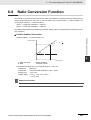
Ratio Conversion Function ................................................................................................... 6-43
Section 7
Common Items
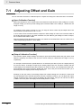
Adjusting Offset and Gain ...................................................................................................... 7-2
7-1-1
7-1-2
7-1-3
Adjustment Mode Operational Flow............................................................................................ 7-3
Input Offset and Gain Adjustment Procedures ........................................................................... 7-4
Output Offset and Gain Adjustment Procedures ........................................................................ 7-9
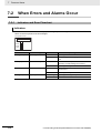
When Errors and Alarms Occur ........................................................................................... 7-14
7-2-1
7-2-2
7-2-3
7-2-4
7-2-5
7-3
Outline of Data Exchange......................................................................................................... 6-20
Accessing from the User Program............................................................................................ 6-21
Allocating Device Variables for CJ-series Unit.......................................................................... 6-22
Analog Input Functions and Operating Procedures .......................................................... 6-26
6-6-1
6-6-2
6-6-3
6-6-4
6-6-5
7-2
Terminal Arrangement .............................................................................................................. 6-15
Internal Circuit .......................................................................................................................... 6-15
Voltage Input Disconnection ..................................................................................................... 6-17
I/O Wiring Example................................................................................................................... 6-18
I/O Wiring Considerations......................................................................................................... 6-19
Exchanging Data with the CPU Unit .................................................................................... 6-20
6-5-1
6-5-2
6-5-3
7-1
Component Names................................................................................................................... 6-11
Indicators .................................................................................................................................. 6-12
Unit Number Switches .............................................................................................................. 6-13
Voltage/Current Switch ............................................................................................................. 6-14
Indicators and Error Flowchart ................................................................................................. 7-14
Alarms Occurring at the Unit .................................................................................................... 7-16
Errors in the CPU Unit .............................................................................................................. 7-19
Restarting Special I/O Units ..................................................................................................... 7-20
Troubleshooting ........................................................................................................................ 7-20
Event Logs ............................................................................................................................. 7-23
7-3-1
7-3-2
7-3-3
Overview of the Event Logs...................................................................................................... 7-23
Error Table ................................................................................................................................ 7-24
Error Descriptions ..................................................................................................................... 7-26
Appendices
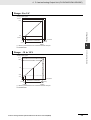
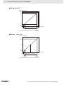
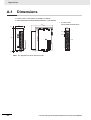
A-1 Dimensions ..............................................................................................................................A-2
A-2 Sample Programs ....................................................................................................................A-3
A-2-1
A-2-2
A-2-3
A-2-4
A-2-5
A-2-6
Upper and Lower-limit Alarm (Constant Monitoring) .................................................................. A-3
Upper and Lower-limit Alarm (with Standby Sequence) ............................................................. A-4
Scaling ........................................................................................................................................ A-7
Square Root Calculation........................................................................................................... A-10
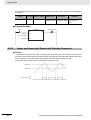
Mean Value Processing ............................................................................................................ A-12
Limit .......................................................................................................................................... A-14
CJ-series Analog I/O Units Operation Manual for NJ-series CPU Unit(W490)
13
CONTENTS
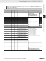
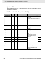
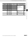
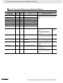
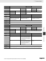
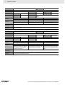
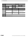
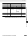
A-3 Functional Differences due to CPU Units (NJ/CJ-series) to be Connected .....................A-16
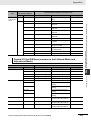
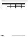
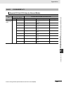
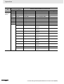
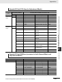
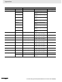
A-4 Correspondence Tables for Device Variables for CJ-series Units
and Memory Addresses for CJ-series Units .....................................................................A-17
A-4-1
A-4-2
A-4-3
A-4-4
A-4-5
A-4-6
A-4-7
A-4-8
CJ1W-AD041-V1.......................................................................................................................A-18
CJ1W-AD081-V1.......................................................................................................................A-21
CJ1W-AD042 ............................................................................................................................A-25
CJ1W-DA021 ............................................................................................................................A-27
CJ1W-DA041 ............................................................................................................................A-28
CJ1W-DA08V/08C ....................................................................................................................A-30
CJ1W-DA042V ..........................................................................................................................A-34
CJ1W-MAD42 ...........................................................................................................................A-36
Index
14
CJ-series Analog I/O Units Operation Manual for NJ-series CPU Unit(W490)
Read and Understand this Manual
Read and Understand this Manual
Please read and understand this manual before using the products. Please consult your OMRON
representative if you have any questions or comments.
Warranty and Limitations of Liability
WARRANTY
OMRON's exclusive warranty is that the products are free from defects in materials and workmanship for a
period of one year (or other period if specified) from date of sale by OMRON.
OMRON MAKES NO WARRANTY OR REPRESENTATION, EXPRESS OR IMPLIED, REGARDING NONINFRINGEMENT, MERCHANTABILITY, OR FITNESS FOR PARTICULAR PURPOSE OF THE
PRODUCTS. ANY BUYER OR USER ACKNOWLEDGES THAT THE BUYER OR USER ALONE HAS
DETERMINED THAT THE PRODUCTS WILL SUITABLY MEET THE REQUIREMENTS OF THEIR
INTENDED USE. OMRON DISCLAIMS ALL OTHER WARRANTIES, EXPRESS OR IMPLIED.
LIMITATIONS OF LIABILITY
OMRON SHALL NOT BE RESPONSIBLE FOR SPECIAL, INDIRECT, OR CONSEQUENTIAL DAMAGES,
LOSS OF PROFITS OR COMMERCIAL LOSS IN ANY WAY CONNECTED WITH THE PRODUCTS,
WHETHER SUCH CLAIM IS BASED ON CONTRACT, WARRANTY, NEGLIGENCE, OR STRICT
LIABILITY.
In no event shall the responsibility of OMRON for any act exceed the individual price of the product on which
liability is asserted.
IN NO EVENT SHALL OMRON BE RESPONSIBLE FOR WARRANTY, REPAIR, OR OTHER CLAIMS
REGARDING THE PRODUCTS UNLESS OMRON'S ANALYSIS CONFIRMS THAT THE PRODUCTS
WERE PROPERLY HANDLED, STORED, INSTALLED, AND MAINTAINED AND NOT SUBJECT TO
CONTAMINATION, ABUSE, MISUSE, OR INAPPROPRIATE MODIFICATION OR REPAIR.
CJ-series Analog I/O Units Operation Manual for NJ-series CPU Unit(W490)
15
Read and Understand this Manual
Application Considerations
SUITABILITY FOR USE
OMRON shall not be responsible for conformity with any standards, codes, or regulations that apply to the
combination of products in the customer's application or use of the products.
At the customer's request, OMRON will provide applicable third party certification documents identifying
ratings and limitations of use that apply to the products. This information by itself is not sufficient for a
complete determination of the suitability of the products in combination with the end product, machine,
system, or other application or use.
The following are some examples of applications for which particular attention must be given. This is not
intended to be an exhaustive list of all possible uses of the products, nor is it intended to imply that the uses
listed may be suitable for the products:
• Outdoor use, uses involving potential chemical contamination or electrical interference, or conditions or
uses not described in this manual.
• Nuclear energy control systems, combustion systems, railroad systems, aviation systems, medical
equipment, amusement machines, vehicles, safety equipment, and installations subject to separate
industry or government regulations.
• Systems, machines, and equipment that could present a risk to life or property.
Please know and observe all prohibitions of use applicable to the products.
NEVER USE THE PRODUCTS FOR AN APPLICATION INVOLVING SERIOUS RISK TO LIFE OR
PROPERTY WITHOUT ENSURING THAT THE SYSTEM AS A WHOLE HAS BEEN DESIGNED TO
ADDRESS THE RISKS, AND THAT THE OMRON PRODUCTS ARE PROPERLY RATED AND
INSTALLED FOR THE INTENDED USE WITHIN THE OVERALL EQUIPMENT OR SYSTEM.
PROGRAMMABLE PRODUCTS
OMRON shall not be responsible for the user's programming of a programmable product, or any
consequence thereof.
16
CJ-series Analog I/O Units Operation Manual for NJ-series CPU Unit(W490)
Read and Understand this Manual
Disclaimers
CHANGE IN SPECIFICATIONS
Product specifications and accessories may be changed at any time based on improvements and other
reasons.
It is our practice to change model numbers when published ratings or features are changed, or when
significant construction changes are made. However, some specifications of the products may be changed
without any notice. When in doubt, special model numbers may be assigned to fix or establish key
specifications for your application on your request. Please consult with your OMRON representative at any
time to confirm actual specifications of purchased products.
DIMENSIONS AND WEIGHTS
Dimensions and weights are nominal and are not to be used for manufacturing purposes, even when
tolerances are shown.
PERFORMANCE DATA
Performance data given in this manual is provided as a guide for the user in determining suitability and does
not constitute a warranty. It may represent the result of OMRON's test conditions, and the users must
correlate it to actual application requirements. Actual performance is subject to the OMRON Warranty and
Limitations of Liability.
ERRORS AND OMISSIONS
The information in this manual has been carefully checked and is believed to be accurate; however, no
responsibility is assumed for clerical, typographical, or proofreading errors, or omissions.
CJ-series Analog I/O Units Operation Manual for NJ-series CPU Unit(W490)
17
Safety Precautions
Safety Precautions
Definition of Precautionary Information
The following notation is used in this manual to provide precautions required to ensure safe usage of a
CJ-series Analog I/O Unit. The safety precautions that are provided are extremely important to safety.
Always read and heed the information provided in all safety precautions.
The following notation is used.
WARNING
Caution
Indicates a potentially hazardous situation which, if not avoided,
could result in death or serious injury. Additionally, there may be
severe property damage.
Indicates a potentially hazardous situation which, if not avoided,
may result in minor or moderate injury, or property damage.
Precautions for Safe Use
Indicates precautions on what to do and what not to do to ensure safe usage of the product.
Precautions for Correct Use
Indicates precautions on what to do and what not to do to ensure proper operation and performance.
18
CJ-series Analog I/O Units Operation Manual for NJ-series CPU Unit(W490)
Safety Precautions
Symbols
The circle and slash symbol indicates operations that you must not do.
The specific operation is shown in the circle and explained in text.
This example indicates prohibiting disassembly.
The triangle symbol indicates precautions (including warnings).
The specific operation is shown in the triangle and explained in text.
This example indicates a precaution for electric shock.
The triangle symbol indicates precautions (including warnings).
The specific operation is shown in the triangle and explained in text.
This example indicates a general precaution.
The filled circle symbol indicates operations that you must do.
The specific operation is shown in the circle and explained in text.
This example shows a general precaution for something that you must do.
CJ-series Analog I/O Units Operation Manual for NJ-series CPU Unit(W490)
19
Safety Precautions
WARNING
During Power Supply
Do not touch any of the terminals or terminal blocks while the power is being
supplied. Doing so may result in electric shock.
Do not attempt to take any Unit apart. In particular, high-voltage parts are
present in the Power Supply Unit while power is supplied or immediately
after power is turned OFF. Touching any of these parts may result in electric
shock. There are sharp parts inside the Unit that may cause injury.
Fail-safe Measures
Provide safety measures in external circuits to ensure safety in the system if
an abnormality occurs due to malfunction of the CPU Unit, other Units, or
slaves or due to other external factors affecting operation. Not doing so may
result in serious accidents due to incorrect operation.
Emergency stop circuits, interlock circuits, limit circuits, and similar safety
measures must be provided in external control circuits.
The Controller outputs may remain ON or OFF due to deposition or burning
of the output relays or destruction of the output transistors. As a countermeasure for such problems, external safety measures must be provided to
ensure safe operation of the system.
The CPU Unit will turn OFF all outputs from Basic Output Units in the following cases. The remote I/O slaves will operate according to the settings in the
slaves.
•
•
•
•
•
If an error occurs in the power supply
If the power supply connection becomes faulty
If a CPU watchdog timer error or CPU reset occurs
If a major fault level Controller error occurs
While the CPU Unit is on standby until RUN mode is entered after the
power is turned ON
External safety measures must be provided to ensure safe operation of the
system in such cases.
If external power supplies for slaves or other devices are overloaded or
short-circuited, the voltage will drop, outputs will turn OFF, and the system
may be unable to read inputs. Provide external safety measures in controls
with monitoring of external power supply voltage as required so that the system operates safely in such a case.
20
CJ-series Analog I/O Units Operation Manual for NJ-series CPU Unit(W490)
Safety Precautions
WARNING
Fail-safe Measures
Unintended outputs may occur when an error occurs in variable memory or
in memory used for CJ-series Units. As a countermeasure for such problems, external safety measures must be provided to ensure safe operation of
the system.
Provide measures in the communications system and user program to
ensure safety in the overall system even if errors or malfunctions occur in
data link communications or remote I/O communications.
If there is interference in remote I/O communications or if a major fault level
error occurs, output status will depend on the products that are used.
Confirm the operation that will occur when there is interference in communications or a major fault level error, and implement safety measures.
Correctly set all of the EtherCAT slaves.
The NJ-series Controller continues normal operation for a certain period of
time when a momentary power interruption occurs. This means that the NJseries Controller may receive incorrect signals from external devices that are
also affected by the power interruption. Accordingly, take suitable actions,
such as external fail-safe measures and interlock conditions, to monitor the
power supply voltage of the external device as required.
You must take fail-safe measures to ensure safety in the event of incorrect,
missing, or abnormal signals caused by broken signal lines, momentary
power interruptions, or other causes. Not doing so may result in serious accidents due to incorrect operation.
Voltage and Current Inputs
Make sure that the voltages and currents that are input to the Units and
slaves are within the specified ranges.
Inputting voltages or currents that are outside of the specified ranges may
cause accidents or fire.
Downloading
Always confirm safety at the destination before you transfer a user program,
configuration data, setup data, device variables, or values in memory used
for CJ-series Units from the Sysmac Studio. The devices or machines may
perform unexpected operation regardless of the operating mode of the CPU
Unit.
CJ-series Analog I/O Units Operation Manual for NJ-series CPU Unit(W490)
21
Safety Precautions
Caution
Application
Do not touch any Unit when power is being supplied or immediately after the
power supply is turned OFF. Doing so may result in burn injury.
Wiring
Be sure that all terminal screws and cable connector screws are tightened to
the torque specified in the relevant manuals. The loose screws may result in
fire or malfunction.
Online Editing
Execute online editing only after confirming that no adverse effects will be
caused by deviations in the timing of I/O. If you perform online editing, the
task execution time may exceed the task period, I/O may not be refreshed
with external devices, input signals may not be read, and output timing may
change.
Using Analog I/O Units
With the CJ1W-AD042/-DA042V, always connect surge suppressors to
inductive loads in the system (e.g., magnetic contactors, relays, and solenoids). Always separate devices that generate surge from the Analog I/O
Units.
Faulty Unit operation may cause unexpected system operation.
22
CJ-series Analog I/O Units Operation Manual for NJ-series CPU Unit(W490)
Precautions for Safe Use
Precautions for Safe Use
Disassembly and Dropping
• Do not attempt to disassemble, repair, or modify any Units. Doing so may result in malfunction or fire.
• Do not drop any Unit or subject it to abnormal vibration or shock. Doing so may result in Unit malfunction or burning.
Mounting
• The sliders on the tops and bottoms of the Power Supply Unit, CPU Unit, I/O Units, and other Units
must be completely locked (until they click into place) after connecting the adjacent Unit connectors.
Installation
• Always connect to a ground of 100 Ω or less when installing the Units. A ground of 100 Ω or less
must be installed when shorting the GR and LG terminals on the Power Supply Unit.
Wiring
• Follow the instructions in this manual to correctly perform wiring.
Double-check all wiring and switch settings before turning ON the power supply.
• Use crimp terminals for wiring.
Do not connect bare stranded wires directly to terminals.
• Do not pull on the cables or bend the cables beyond their natural limit.
Do not place heavy objects on top of the cables or other wiring lines. Doing so may break the cables.
• Mount terminal blocks and connectors only after checking the mounting location carefully.
• Be sure that the terminal blocks, expansion cables, and other items with locking devices are properly
locked into place.
• Always remove any dustproof labels that are on the top of the Units when they are shipped before
you turn ON the power supply. If the labels are not removed, heat will accumulate and malfunctions
may occur.
• Before you connect a computer to the CPU Unit, disconnect the power supply plug of the computer
from the AC outlet. Also, if the computer has an FG terminal, make the connections so that the FG
terminal has the same electrical potential as the GR terminal on the Power Supply Unit. A difference
in electric potential between the computer and Controller may cause failure or malfunction.
• If the external power supply to an Output Unit or slave has polarity, connect it with the correct polarity. If the polarity is reversed, current may flow in the reverse direction and damage the connected
devices regardless of the operation of the Controller.
Power Supply Design
• Do not exceed the rated supply capacity of the Power Supply Units in the NJ-series Controller. The
rated supply capacities are given in the NJ-series CPU Unit Hardware User’s Manual (Cat. No.
W500).
If the capacity is exceeded, operation may stop, malfunctions may occur, or data may not be backed
up normally for power interruptions.
Use NJ-series Power Supply Units for both the NJ-series CPU Rack and Expansion Racks.
Operation is not possible if a CJ-series Power Supply Unit is used with an NJ-series CPU Unit or an
NJ-series Power Supply Unit is used with a CJ-series CPU Unit.
CJ-series Analog I/O Units Operation Manual for NJ-series CPU Unit(W490)
23
Precautions for Safe Use
• Do not apply voltages or connect loads to the Output Units or slaves in excess of the maximum ratings.
• Surge current occurs when the power supply is turned ON. When selecting fuses or breakers for
external circuits, consider the above precaution and allow sufficient margin in shut-off performance.
Refer to the relevant manuals for surge current specifications. Refer to the NJ-series CPU Unit Hardware User’s Manual (Cat. No. W500) for surge current specifications.
• If the full dielectric strength voltage is applied or turned OFF using the switch on the tester, the generated impulse voltage may damage the Power Supply Unit. Use the adjustment on the tester to gradually increase and decrease the voltage.
• Apply the voltage between the Power Supply Unit's L1 or L2 terminal and the GR terminal when testing insulation and dielectric strength.
• Do not supply AC power from an inverter or other device with a square-wave output. Internal temperature rise may result in smoking or burning. Always input a sinusoidal wave with the frequency that is
given in the NJ-series CPU Unit Hardware User’s Manual (Cat. No. W500).
• Install external breakers and take other safety measures against short-circuiting in external wiring.
Turning ON the Power Supply
• It takes up to approximately 10 to 20 s to enter RUN mode after the power is turned ON. During that
time, outputs will be OFF or will be the values specified in the Unit or slave settings, and external
communications cannot be performed. Use the RUN output on the Power Supply Unit, for example,
to implement fail-safe circuits so that external devices do not operate incorrectly.
• Configure the external circuits so that the power supply to the control system turns ON only after the
power supply to the Controller has turned ON. If the power supply to the Controller is turned ON after
the control power supply, temporary errors may result in incorrect control system signals because the
output terminals on Output Units may momentarily turn ON when power supply is turned ON to the
Controller.
• If you transfer data from a backup file on an SD Memory Card to the Controller when the power supply is turned ON, properly select the data groups to transfer. If the data for an unintended data group
is transferred to the Controller, it may cause the equipment to operate unpredictably.
Actual Operation
• Check the user program, data, and parameter settings for proper execution before you use them for
actual operation.
Turning OFF the Power Supply
• Never turn OFF the power supply to the Controller when the BUSY indicator is flashing. While the
BUSY indicator is lit, the user program and settings in the CPU Unit are being backed up in the builtin non-volatile memory. This data will not be backed up correctly if the power supply is turned OFF.
Also, a major fault level Controller error will occur the next time you start operation, and operation will
stop.
• Do not turn OFF the power supply or remove the SD Memory Card while SD Memory Card access is
in progress (i.e., while the SD BUSY indicator flashes). Data may become corrupted, and the Controller will not operate correctly if it uses corrupted data. To remove the SD Memory Card from the CPU
Unit while the power supply is ON, press the SD Memory Card power supply switch and wait for the
SD BUSY indicator to turn OFF before you remove the SD Memory Card.
• Do not disconnect the cable or turn OFF the power supply to the Controller when downloading data
or the user program from Support Software.
• Always turn OFF the power supply to the Controller before you attempt any of the following.
• Mounting or removing I/O Units or the CPU Unit
• Assembling the Units
• Setting DIP switches or rotary switches
24
CJ-series Analog I/O Units Operation Manual for NJ-series CPU Unit(W490)
Precautions for Safe Use
• Connecting cables or wiring the system
• Connecting or disconnecting the connectors
The Power Supply Unit may continue to supply power to the rest of the Controller for a few seconds
after the power supply turns OFF. The PWR indicator is lit during this time. Confirm that the PWR
indicator is not lit before you perform any of the above.
Operation
• Confirm that no adverse effect will occur in the system before you attempt any of the following.
• Changing the operating mode of the CPU Unit (including changing the setting of the Operating
Mode at Startup)
• Changing the user program or settings
• Changing set values or present values
• Forced refreshing
• Always sufficiently check the safety at the connected devices before you change the settings of an
EtherCAT slave or Special Unit.
• If two different function modules are used together, such as when you use CJ-series Basic Output
Units and EtherCAT slave outputs, take suitable measures in the user program and external controls
to ensure that safety is maintained in the controlled system if one of the function modules stops. The
relevant outputs will stop if a partial fault level error occurs in one of the function modules.
• Always confirm safety at the connected equipment before you reset Controller errors with an event
level of partial fault or higher for the EtherCAT Master Function Module.
When the error is reset, all slaves that were in any state other than Operational state due to a Controller error with an event level of partial fault or higher (in which outputs are disabled) will go to Operational state and the outputs will be enabled.
Before you reset all errors, confirm that no Controller errors with an event level of partial fault have
occurred for the EtherCAT Master Function Module.
• Always confirm safety at the connected equipment before you reset Controller errors for a CJ-series
Special Unit. When a Controller error is reset, the Unit where the Controller error with an event level
of observation or higher will be restarted.
Before you reset all errors, confirm that no Controller errors with an event level of observation or
higher have occurred for the CJ-series Special Unit. Observation level events do not appear on the
Controller Error Tab Page, so it is possible that you may restart the CJ-series Special Unit without
intending to do so.
You can check the status of the _CJB_UnitErrSta[0,0] to _CJB_UnitErrSta[3,9] error status variables
on a Watch Tab Page to see if an observation level Controller error has occurred.
Battery Backup
• The user program and initial values for the variables are stored in non-volatile memory in the CPU
Unit. The present values of variables with the Retain attribute and the values of the Holding, DM, and
EM Areas in the memory used for CJ-series Units are backed up by a Battery. If the Battery is not
connected or the Battery is exhausted, the CPU Unit detects a Battery-backup Memory Check Error.
If that error is detected, variables with a Retain attribute are set to their initial values and the Holding,
DM, and EM Areas in memory used for CJ-series Units are cleared to all zeros. Perform thorough
verifications and provide sufficient measures to ensure that the devices perform safe operation for
the initial values of the variables with Retain attributes and the resulting operation.
Debugging
• Forced refreshing ignores the results of user program execution and refreshes I/O with the specified
values. If forced refreshing is used for inputs for which I/O refreshing is not supported, the inputs will
first take the specified values, but they will then be overwritten by the user program. This operation
differs from the force-set/reset functionality of the CJ-series PLCs.
CJ-series Analog I/O Units Operation Manual for NJ-series CPU Unit(W490)
25
Precautions for Safe Use
• You cannot upload or download information for forced refreshing with the Sysmac Studio.
After downloading data that contains forced refreshing, change to RUN mode and then use the Sysmac Studio to perform the operation for forced refreshing.
Depending on the difference in the forced status, the control system may operate unexpectedly.
• Do not specify the same address for the AT specification for more than one variable.
Doing so would allow the same entity to be accessed with different variable names, which would
make the user program more difficult to understand and possibly cause programming mistakes.
General Communications
• When you use data link communications, check the error information that is given in ErrSta (Controller Error Status) to make sure that no error has occurred in the source device. Write the user program
to use the received data only if there is no error. If there is an error in the source device, the data for
the data link may contain incorrect values.
• Unexpected operation may result if inappropriate data link tables are set. Even if appropriate data link
tables have been set, confirm that the controlled system will not be adversely affected before you
transfer the data link tables. The data links start automatically after the data link tables are transferred.
• All CPU Bus Units are restarted when routing tables are transferred from Support Software to the
CPU Unit. Confirm that the system will not be adversely affected by restarting before you transfer the
routing tables.
• Tag data links will stop between related nodes while tag data link parameters are transferred during
Controller operation. Confirm that the system will not be adversely affected before you transfer the
tag data link parameters.
EtherNet/IP Communications
• All related EtherNet/IP nodes are reset when you transfer settings for the built-in EtherNet/IP port
(including IP addresses and tag data links settings). Confirm that the system will not be adversely
affected by resetting nodes before you transfer the settings.
• If EtherNet/IP tag data links (cyclic communications) are used with a repeating hub, the communications load on the network will increase. This will increase collisions and may prevent stable communications. Do not use repeating hubs on networks where tag data links are used. Use an Ethernet
switch instead.
EtherCAT Communications
• Make sure that the communications distance, number of nodes connected, and method of connection
for EtherCAT are within specifications.
Do not connect EtherCAT communications to EtherNet/IP, a standard in-house LAN, or other networks. An overload may cause the network to fail or malfunction.
• Malfunctions or unexpected operation may occur for some combinations of EtherCAT revisions of the
master and slaves. If you disable the revision check in the network settings, use the Sysmac Studio
to check the slave revision settings in the master and the actual slave revisions, and then make sure
that functionality is compatible in the slave manuals or other references. You can check the actual
slave revisions from the Sysmac Studio or on slave nameplates.
• After you transfer the user program, the CPU Unit is restarted and communications with the EtherCAT slaves are cut off. During that period, the slave outputs behave according to the slave settings.
The time that communications are cut off depends on the EtherCAT network configuration. If the
EtherCAT network configuration contains only OMRON EtherCAT slaves, communications are cut off
for a maximum of 45 seconds.
Before you transfer the user program, confirm that the system will not be adversely affected.
26
CJ-series Analog I/O Units Operation Manual for NJ-series CPU Unit(W490)
Precautions for Safe Use
• If the Fail-soft Operation parameter is set to stop operation, process data communications will stop
for all slaves when an EtherCAT communications error is detected in a slave. For this reason, if
Servo Drives are connected, the Servos for all axes will be turned OFF. Make sure that the Fail-soft
Operation parameter setting results in safe operation when a device error occurs.
• EtherCAT communications are not always established immediately after the power supply is turned
ON. Use the system-defined variables in the user program to confirm that communications are established before attempting control operations.
• If frames sent to EtherCAT slaves are lost due to noise or other causes, slave I/O data is not communicated, and the intended operation is sometimes not achieved. If noise countermeasures are
required, use the _EC_InDataInvalid (Input Data Disable) system-defined variable as an interlock
condition in the user program.
Refer to the NJ-series CPU Unit Built-in EtherCAT Port User’s Manual (Cat. No. W505) for details.
The slave outputs behave according to the slave settings. Refer to the manuals for the slaves for
details.
• When an EtherCAT slave is disconnected, communications will stop and control of the outputs will be
lost not only for the disconnected slave, but for all slaves connected after it. Confirm that the system
will not be adversely affected before you disconnect a slave.
• If you disconnect the cable from an EtherCAT slave to disconnect it from the network, any current
communications frames may be lost. If frames are lost, slave I/O data is not communicated, and the
intended operation is sometimes not achieved. Perform the following processing for a slave that
needs to be replaced.
Program the _EC_InDataInvalid (Input Data Disable) system-defined variable as an interlock condition.
Set the Impermissible Number of Continuous Timeouts setting in the EtherCAT master to at least
2.
Refer to the NJ-series CPU Unit Built-in EtherCAT Port User’s Manual (Cat. No. W505) for details.
Motion Control
• Confirm the axis number carefully before you perform an MC Test Run.
• The motor is stopped if communications are interrupted between the Sysmac Studio and the CPU
Unit during an MC Test Run. Connect the communications cable between the computer and CPU
Unit securely and confirm that the system will not be adversely affected before you perform an MC
Test Run.
• Always execute the Save Cam Table instruction if you change any of the cam data from the user program in the CPU Unit or from the Sysmac Studio. If the cam data is not saved, the previous condition
will be restored when the power is turned ON again, possibly causing unexpected machine operation.
• The positive drive prohibit input (POT), negative drive prohibit input (NOT), and home proximity input
(DEC) of the Servo Drive are used by the MC Function Module as the positive limit input, negative
limit input, and home proximity input. Make sure that the signal widths for all of these input signals
are longer than the control period of the MC Function Module. If the input signal widths are shorter
than the control period, the MC Function Module may not be able to detect the input signals, resulting
in incorrect operation.
Battery Replacement
• The Battery may leak, rupture, heat, or ignite. Never short-circuit, charge, disassemble, heat, or
incinerate the Battery or subject it to strong shock.
• Dispose of any Battery that has been dropped on the floor or otherwise subjected to excessive
shock. Batteries that have been subjected to shock may leak if they are used.
• UL standards require that only an experienced engineer replace the Battery. Make sure that an experienced engineer is in charge of Battery replacement.
CJ-series Analog I/O Units Operation Manual for NJ-series CPU Unit(W490)
27
Precautions for Safe Use
• Apply power for at least five minutes before changing the Battery. Install a new Battery within five
minutes (at 25°C) of turning OFF the power supply. If power is not supplied for at least 5 minutes, the
saved data may be lost.
Unit Replacement
• We recommend replacing the Battery with the power turned OFF to prevent the CPU Unit’s sensitive
internal components from being damaged by static electricity and to prevent malfunctions. The Battery can be replaced without turning OFF the power supply. To do so, always touch a grounded piece
of metal to discharge static electricity from your body before you start the procedure.
After you replace the Battery, connect the Sysmac Studio and clear the Low Battery Voltage error.
• Make sure that the required data, including the user program, configurations, settings, variables, and
memory used for CJ-series Units, is transferred to a CPU Unit that was replaced and to externally
connected devices before restarting operation.
Be sure to include the routing tables, network parameters, and other CPU Bus Unit data, which are
stored in the CPU Unit.
Disposal
• Dispose of the product and Batteries according to local ordinances as they apply.
• The following information must be displayed for all products that contain primary lithium batteries with
a perchlorate content of 6 ppb or higher when shipped to or transported through the State of California, USA.
Perchlorate Material - special handling may apply.
See www.dtsc.ca.gov/hazardouswaste/perchlorate.
• The CPU Unit contains a primary lithium battery with a perchlorate content of 6 ppb or higher. Place
the above information on the individual boxes and shipping boxes when shipping finished products
that contain a CPU Unit to the State of California, USA.
28
CJ-series Analog I/O Units Operation Manual for NJ-series CPU Unit(W490)
Precautions for Correct Use
Precautions for Correct Use
Storage, Mounting, and Wiring
• Do not operate or store the Controller in the following locations. Operation may stop or malfunctions
may occur.
• Locations subject to direct sunlight
• Locations subject to temperatures or humidity outside the range specified in the specifications
• Locations subject to condensation as the result of severe changes in temperature
• Locations subject to corrosive or flammable gases
• Locations subject to dust (especially iron dust) or salts
• Locations subject to exposure to water, oil, or chemicals
• Locations subject to shock or vibration
• Take appropriate and sufficient countermeasures when installing the Controller in the following locations.
• Locations subject to strong, high-frequency noise
• Locations subject to static electricity or other forms of noise
• Locations subject to strong electromagnetic fields
• Locations subject to possible exposure to radioactivity
• Locations close to power lines
• Before touching a Unit, be sure to first touch a grounded metallic object in order to discharge any
static build-up.
• Install the Controller away from sources of heat and ensure proper ventilation. Not doing so may
result in malfunction, in operation stopping, or in burning.
• An I/O bus check error will occur and the Controller will stop if an I/O Connecting Cable’s connector is
disconnected from the Rack. Be sure that the connectors are secure.
• Do not allow foreign matter to enter the openings in the Unit. Doing so may result in Unit burning,
electric shock, or failure.
• Do not allow wire clippings, shavings, or other foreign material to enter any Unit. Otherwise, Unit
burning, failure, or malfunction may occur. Cover the Units or take other suitable countermeasures,
especially during wiring work.
• For EtherCAT and EtherNet/IP, use the connection methods and cables that are specified in the NJseries CPU Unit Built-in EtherCAT Port User’s Manual (Cat. No. W505) and the NJ-series CPU Unit
Built-in EtherNet/IP Port User’s Manual (Cat. No. W506). Otherwise, communications may be faulty.
• Use the rated power supply voltage for the Power Supply Units. Take appropriate measures to
ensure that the specified power with the rated voltage and frequency is supplied in places where the
power supply is unstable.
• Make sure that the current capacity of the wire is sufficient. Otherwise, excessive heat may be generated. When cross-wiring terminals, the total current for all the terminals will flow in the wire. When
wiring cross-overs, make sure that the current capacity of each of the wires is not exceeded.
• Do not touch the terminals on the Power Supply Unit immediately after turning OFF the power supply. Residual voltage may cause electrical shock.
• If you use reed switches for the input contacts for AC Input Units, use switches with a current capacity of 1 A or greater.
If the capacity of the reed switches is too low, surge current may fuse the contacts.
CJ-series Analog I/O Units Operation Manual for NJ-series CPU Unit(W490)
29
Precautions for Correct Use
Error Processing
• In applications that use the results of instructions that read the error status, consider the affect on the
system when errors are detected and program error processing accordingly. For example, even the
detection of a minor error, such as Battery replacement during operation, can affect the system
depending on how the user program is written.
• If you change the event level of a Controller error, the output status when the error occurs may also
change. Confirm safety before you change an event level.
Restoring and Automatically Transferring Data
• When you edit the restore command file or the automatic transfer command file, do not change anything in the file except for the “yes” and “no” specifications for the selectable data groups. If you
change anything else in the file, the Controller may perform unexpected operation when you restore
or automatically transfer the data.
Unit Replacement
• If you replace a CPU Bus Unit or Special I/O Unit, refer to operation manual for the Unit for information on the data required for individual Units and redo the necessary settings.
• The absolute encoder home offset is backed up with a Battery in the CPU Unit.
When you change the combination of the CPU Unit and Servomotor, e.g., when you add or replace a
Servomotor, define home again.
To restore the information without changing the CPU Unit-Servomotor combination, remove the
absolute encoder home offset from the data to restore.
Task Settings
• If a Task Period Exceeded error occurs, shorten the programs to fit in the task period or increase the
setting of the task period.
Motion Control
• Use the system-defined variable in the user program to confirm that EtherCAT communications are
established before you attempt to execute motion control instructions. Motion control instructions are
not executed normally if EtherCAT communications are not established.
• Use the system-defined variables to monitor for errors in communications with the slaves that are
controlled by the motion control function module. Motion control instructions are not executed normally if an error occur in slave communications.
• Before you start an MC Test Run, make sure that the operation parameters are set correctly.
• Do not download motion control settings during an MC Test Run.
EtherCAT Communications
• Do not disconnect the EtherCAT slave cables during operation. The outputs will become unstable.
• Set the Servo Drives to stop operation if an error occurs in EtherCAT communications between the
Controller and a Servo Drive.
• Make sure that all of the slaves to be restored are participating in the network before you reset a Network Configuration Verification Error, Process Data Communications Error, or Link OFF Error in the
EtherCAT Master Function Module. If any slave is not participating when any of these errors is reset,
the EtherCAT Master Function Module may access slave with a different node address than the specified node address or the error may not be reset correctly.
30
CJ-series Analog I/O Units Operation Manual for NJ-series CPU Unit(W490)
Precautions for Correct Use
Battery Replacement
• Be sure to install a replacement Battery within two years of the production date shown on the Battery
label.
• Turn ON the power after replacing the Battery for a CPU Unit that has been unused for a long time.
Leaving the CPU Unit unused again without turning ON the power even once after the Battery is
replaced may result in a shorter Battery life.
• When you replace the Battery, use the CJ1W-BAT01 Battery Set.
SD Memory Cards
• Insert the SD Memory Card all the way.
• Do not turn OFF the power supply to the Controller during SD Memory Card access. The files may be
corrupted.
If there is a corrupted file in the SD Memory Card, the file is automatically deleted by the restoration
function when the power supply is turned ON.
CJ-series Analog I/O Units Operation Manual for NJ-series CPU Unit(W490)
31
Regulations and Standards
Regulations and Standards
Conformance to EC Directives
Applicable Directives
• EMC Directives
• Low Voltage Directive
Concepts
z EMC Directive
OMRON devices that comply with EC Directives also conform to the related EMC standards so that
they can be more easily built into other devices or the overall machine. The actual products have
been checked for conformity to EMC standards.*
Whether the products conform to the standards in the system used by the customer, however, must
be checked by the customer. EMC-related performance of the OMRON devices that comply with EC
Directives will vary depending on the configuration, wiring, and other conditions of the equipment or
control panel on which the OMRON devices are installed. The customer must, therefore, perform
the final check to confirm that devices and the overall machine conform to EMC standards.
* Applicable EMC (Electromagnetic Compatibility) standards are as follows:
EMS (Electromagnetic Susceptibility): EN 61131-2 and EN 61000-6-2
EMI (Electromagnetic Interference): EN 61131-2 and EN 61000-6-4 (Radiated emission: 10-m regulations)
z Low Voltage Directive
Always ensure that devices operating at voltages of 50 to 1,000 VAC and 75 to 1,500 VDC meet the
required safety standards. The applicable directive is EN 61131-2.
z Conformance to EC Directives
The NJ-series Controllers comply with EC Directives. To ensure that the machine or device in which
the NJ-series Controller is used complies with EC Directives, the Controller must be installed as follows:
• The NJ-series Controller must be installed within a control panel.
• You must use reinforced insulation or double insulation for the DC power supplies connected to
DC Power Supply Units and I/O Units.
• NJ-series Controllers that comply with EC Directives also conform to the Common Emission Standard (EN 61000-6-4). Radiated emission characteristics (10-m regulations) may vary depending
on the configuration of the control panel used, other devices connected to the control panel, wiring, and other conditions.
You must therefore confirm that the overall machine or equipment complies with EC Directives.
32
CJ-series Analog I/O Units Operation Manual for NJ-series CPU Unit(W490)
Regulations and Standards
Conditions for Conforming to EMC Directives
The following immunity test conditions apply to CS/CJ-series Analog I/O Units.
Overall Accuracy
Analog Input Unit
Analog Output
Units
Analog I/O Unit
CS1W-AD161
+4%/−6%
CJ1W-AD041-V1/AD081-V1
+3%/−6%
CJ1W-AD042
+6%/−6%
CJ1W-DA021/DA041
+4%/−1%
CJ1W-DA08V/DA08C
+4%/−4%
CJ1W-DA042V
+4.5%/−4.5%
CS1W-MAD44
+2%/−1%
CJ1W-MAD42
+4%/−4%
Use shielded twisted-pair cable to connect analog inputs and connect the shield on the input line to the
AG terminal.
CJ-series Analog I/O Units Operation Manual for NJ-series CPU Unit(W490)
33
Regulations and Standards
Conformance to Shipbuilding Standards
The NJ-series Controllers comply with the following shipbuilding standards. Applicability to the shipbuilding standards is based on certain usage conditions. It may not be possible to use the product in
some locations. Contact your OMRON representative before attempting to use a Controller on a
ship.
Usage Conditions for NK and LR Shipbuilding Standards
• The NJ-series Controller must be installed within a control panel.
• Gaps in the door to the control panel must be completely filled or covered with gaskets or other
material.
• The following noise filter must be connected to the power supply line.
Noise Filter
Manufacturer
Cosel Co., Ltd.
Model
TAH-06-683
Trademarks
• Sysmac and SYSMAC are trademarks or registered trademarks of OMRON Corporation in Japan
and other countries for OMRON factory automation products.
• Windows, Windows 98, Windows XP, Windows Vista, and Windows 7 are registered trademarks of
Microsoft Corporation in the USA and other countries.
• EtherCAT is registered trademark and patented technology, licensed by Beckhoff Automation
GmbH, Germany.
• The SD logo is a trademark of SD-3C, LLC.
Other company names and product names in this document are the trademarks or registered trademarks of their respective companies.
34
CJ-series Analog I/O Units Operation Manual for NJ-series CPU Unit(W490)
Unit Versions
Unit Versions
Unit Versions
A “unit version” has been introduced to manage CPU Units in the NJ Series according to differences in
functionality accompanying Unit upgrades.
Notation of Unit Versions on Products
The unit version is given on the ID information label of the products for which unit versions are managed, as shown below.
Example for NJ-series NJ501-@@@@ CPU Unit:
ID information label
Unit model
NJ501 - 1500
Unit version
Ver.1.@@
PORT1 MAC ADDRESS: @@@@@@@@@@@@
PORT2 MAC ADDRESS: @@@@@@@@@@@@
Lot No. DDMYY@
xxxx
Lot number and serial number
MAC address
The following information is provided on the ID information label.
Item
Description
Unit model
Gives the model of the Unit.
Unit version
Gives the unit version of the Unit.
Lot number and
serial number
Gives the lot number and serial number of the Unit.
DDMYY: Lot number, @: For use by OMRON, xxxx: Serial number
“M” gives the month (1 to 9: January to September, X: October, Y: November, Z: December)
MAC address
Gives the MAC address of the built-in port on the Unit.
Confirming Unit Versions with Sysmac Studio
You can use the Unit Production Information on the Sysmac Studio to check the unit version of the CPU
Unit, CJ-series Special I/O Units, CJ-series CPU Bus Units, and EtherCAT slaves. The unit versions of
CJ-series Basic I/O Units cannot be checked from the Sysmac Studio.
z CPU Unit and CJ-series Units
1
Double-click CPU/Expansion Racks under Configurations and Setup in the Multiview
Explorer. Or, right-click CPU/Expansion Racks under Configurations and Setup and select
Edit from the menu.
The Unit Editor is displayed for the Controller Configurations and Setup layer.
CJ-series Analog I/O Units Operation Manual for NJ-series CPU Unit(W490)
35
Unit Versions
2
Right-click any open space in the Unit Editor and select Production Information.
The Production Information Dialog Box is displayed.
Simple Display
Detailed Display
In this example, “Ver.1.00” is displayed next to the unit model.
The following items are displayed.
CPU Unit
CJ-series Units
Unit model
Unit model
Unit version
Unit version
Lot number
Lot number
Rack number, slot number, and unit number
z EtherCAT Slaves
1
Double-click EtherCAT under Configurations and Setup in the Multiview Explorer. Or, rightclick EtherCAT under Configurations and Setup and select Edit from the menu.
The EtherCAT Configuration Tab Page is displayed for the Controller Configurations and Setup
layer.
2
Right-click the master in the EtherCAT Configurations Editing Pane and select Display Production Information.
The Production Information Dialog Box is displayed.
The following items are displayed.
Node address
Type information*
Serial number
* If the model number cannot be determined (such as when there is no ESI file), the vendor ID, product
code, and revision number are displayed.
36
CJ-series Analog I/O Units Operation Manual for NJ-series CPU Unit(W490)
Related Manuals
Related Manuals
The following manuals are related to the NJ-series Controllers. Use these manuals for reference.
Manual name
NJ-series CPU Unit
Hardware User’s Manual
Cat. No.
W500
Model numbers
NJ501-@@@@
NJ301-@@@@
Application
Description
Learning the basic specifications of the NJ-series
CPU Units, including introductory information,
designing, installation, and
maintenance. Mainly hardware information is provided.
An introduction to the entire NJ-series system is
provided along with the following information on
the CPU Unit.
• Features and system configuration
• Introduction
• Part names and functions
• General specifications
• Installation and wiring
• Maintenance and inspection
Use this manual together with the NJ-series
CPU Unit Software User’s Manual (Cat. No.
W501).
NJ-series CPU Unit Software User’s Manual
W501
NJ501-@@@@
NJ301-@@@@
Learning how to program
and set up an NJ-series
CPU Unit. Mainly software
information is provided.
The following information is provided on a Controller built with an NJ501 CPU Unit.
• CPU Unit operation
• CPU Unit features
• Initial settings
• Programming based on IEC 61131-3 language specifications
Use this manual together with the NJ-series
CPU Unit Hardware User’s Manual (Cat. No.
W500).
Sysmac Studio Version 1
Operation Manual
W504
SYSMACSE2@@@
Learning about the operating procedures and functions of the Sysmac Studio.
Describes the operating procedures of the Sysmac Studio.
CJ-series Analog I/O
Units Operation Manual
for NJ-series CPU Unit
(This Manual)
W490
CJ1W-AD0@@-@@
Learning about the functions and usage of CJseries Analog Input Units,
Analog Output Units, and
Analog I/O Units for using
them in an NJ-series configuration.
The functions and usage of the CJ-series Analog Input Units, Analog Output Units, and Analog I/O Units for using them in an NJ-series
configuration are described.
CS/CJ Series Analog I/O
Units Operation Manual
W345
Learning about the functions and usage of CJseries Analog Input Units,
Analog Output Units, and
Analog I/O Units.
The functions and usage of the CJ-series Analog Input Units, Analog Output Units, and Analog I/O Units for using them in a CJ-series
configuration are described.
CJ1W-DA0@@@
CJ1W-MAD42
CS1W-AD041-V1/
081-V1/161
CS1W-DA041/08V/
08C
CS1W-MAD44
CJ1W-AD041-V1/
081-V1/042
CJ1W-DA021/041/
08V/08C/042V
CJ1W-MAD42
CJ-series Analog I/O Units Operation Manual for NJ-series CPU Unit(W490)
37
Revision History
Revision History
A manual revision code appears as a suffix to the catalog number on the front and back covers of the
manual.
Cat. No. W490-E1-03
Revision code
Revision code
01
02
03
38
Date
July 2011
March 2012
August 2012
Revised content
Original production
Corrected errors.
Made changes accompanying release of unit version 1.03 of
the CPU Unit.
CJ-series Analog I/O Units Operation Manual for NJ-series CPU Unit(W490)
1
System Design
This section describes the features and system configurations of the CJ-series Analog
I/O Units which you can connect to the NJ-series CPU Unit.
1-1 Features and Functions . . . . . . . . . . . . . . . . . . . . . . . . . . . . . . . . . . . . . . . . . 1-2
1-2 Mouting the Unit . . . . . . . . . . . . . . . . . . . . . . . . . . . . . . . . . . . . . . . . . . . . . . . 1-7
1-2-1
1-2-2
1-2-3
Basic System Configuration . . . . . . . . . . . . . . . . . . . . . . . . . . . . . . . . . . . . . . . 1-7
Mounting Procedure . . . . . . . . . . . . . . . . . . . . . . . . . . . . . . . . . . . . . . . . . . . . 1-8
Precautions . . . . . . . . . . . . . . . . . . . . . . . . . . . . . . . . . . . . . . . . . . . . . . . . . . . 1-9
1-3 Function Applications . . . . . . . . . . . . . . . . . . . . . . . . . . . . . . . . . . . . . . . . . 1-10
CJ-series Analog I/O Units Operation Manual for NJ-series CPU Unit(W490)
1-1
1 System Design
1-1
Features and Functions
CJ-series Analog I/O Units
Analog Input Unit
Analog Output Unit
CJ1W-AD041-V1
CJ1W-AD081-V1
CJ1W-DA021
CJ1W-DA041
AD081
RUN
ERC
ERH
ADJ
CJ1W-DA08V
CJ1W-DA08C
DA041
B1
RUN
ERC
ERH
ADJ
A1
Analog I/O Unit
CJ1W-MAD42
DA08V
B1
RUN
ERC
ERH
ADJ
A1
MAD42
B1
RUN
ERC
ERH
ADJ
A1
MACH
MACH
MACH
MACH
No.
1
x10
No.
1
x10
No.
1
x10
No.
1
x10
x10
0
x10
0
x10
1 2
1 2
MODE
MODE
x10
A1
0
CJ1W-DA042V
CJ1W-AD042
DA042V
AD042
R
R
B1
B1
A1
A1
MACH
MACH
No.
1
x10
No.
1
x10
x10
0
B1
x10
0
0
The CJ Series includes CJ1W-AD041-V1, CS1W-AD081-V1, and CJ1W-AD042 Analog Input Units that
convert analog signals to digital signals and transfer them to CJ-series CPU Units. It also includes
CJ1W-DA041, CS1W-DA021, CJ1W-DA042V, CJ1W-DA08V, and CJ1W-DA08C Analog Output Units
that convert digital data from CJ-series CPU Units into analog signals for output, and CJ1W-MAD42
Analog I/O Units that have both analog input and output function.
The main specifications are listed in the following table.
Analog input
Analog
Input
Units
1-2
Unit
Maximum
input points
CJ1W-AD041-V1
4
CJ1W-AD081-V1
8
CJ1W-AD042
4
Input signal
range *
–10 to 10 V
0 to 10 V
0 to 5 V
1 to 5 V
4 to 20 mA
–10 to 10 V
0 to 10 V
–5 to 5 V
1 to 5 V
4 to 20 mA
Analog output
Maximum
output
points
---
Output
signal range *
---
Conversion cycle
1 ms/point
(Can be set to 250
µs/point.)
20 µs for 1 point
25 µs for 2 points
30 µs for 3 points
35 µs for 4 points
CJ-series Analog I/O Units Operation Manual for NJ-series CPU Unit(W490)
1 System Design
Analog
Output
Units
Analog I/O
Units
Unit
Maximum
input points
CJ1W-DA021
---
Analog output
Maximum
output
points
Input signal
range *
---
2
Output
signal range *
Conversion cycle
–10 to 10 V
0 to 10 V
0 to 5 V
1 to 5 V
4 to 20 mA
1 ms/point
1 ms/point
(Can be set to 250
µs/point.)
CJ1W-DA041
4
CJ1W-DA08V
8
–10 to 10 V
0 to 10 V
0 to 5 V
1 to 5 V
CJ1W-DA08C
8
4 to 20 mA
CJ1W-DA042V
4
–10 to 10 V
0 to 10 V
1 to 5 V
20 µs for 1 point
25 µs for 2 points
30 µs for 3 points
35 µs for 4 points
2
–10 to 10 V
0 to 10 V
0 to 5 V
1 to 5 V
4 to 20 mA
1 ms/point
(Can be set to 500
µs/point.)
CJ1W-MAD42
4
–10 to 10 V
0 to 10 V
0 to 5 V
1 to 5 V
4 to 20 mA
1-1 Features and Functions
Analog input
1
* You can separately set the input signal range or output signal range for each input or output.
Unit support for functions is shown in the following table.
Unit
Input
Peak
disconnection
value hold
detection
Output
hold
Mean value
processing
Proportional
conversion
Offset and
gain
adjustment
Scaling
Analog
Input
Units
CJ1W-AD041-V1
Supported. Supported. Not supported. Supported. Not supported. Supported. Not supported.
CJ1W-AD081-V1
Supported. Supported. Not supported. Supported. Not supported. Supported. Not supported.
CJ1W-AD042
Supported. Supported. Not supported. Supported. Not supported. Not supported. Supported.
Analog
Output
Units
CJ1W-DA041
Not supported. Not supported. Supported. Not supported. Not supported. Supported. Not supported.
CJ1W-DA021
Not supported. Not supported. Supported. Not supported. Not supported. Supported. Not supported.
CJ1W-DA08V
Not supported. Not supported. Supported. Not supported. Not supported. Supported. Supported.
CJ1W-DA08C
Not supported. Not supported. Supported. Not supported. Not supported. Supported. Supported.
CJ1W-DA042V
Not supported. Not supported. Supported. Not supported. Not supported. Not supported. Supported.
CJ1W-MAD42
Supported. Supported. Supported. Supported. Supported. Supported. Supported.
Analog
I/O Units
CJ-series Analog I/O Units Operation Manual for NJ-series CPU Unit(W490)
1-3
1 System Design
z Input Disconnection Detection Function
You can use the input disconnection detection function for analog inputs within an input signal range
of 1 to 5 V (4 to 20 mA). Any input under 0.3 V (1.2 mA) will be regarded as a disconnection. For
details, refer to 2-6-4, 3-6-5 or 6-6-5.
Analog Input Unit
CPU Unit
Disconnection
Detected Bit
z Peak Value Hold Function
The peak value hold function holds the maximum digital conversion value for every input (this
includes mean value processing). You can use this function with analog input. The following diagram
shows how digital conversion values are affected when the peak value hold function is used. For
details, refer to 2-6-3, 3-6-4 or 6-6-3.
Peak Value Hold Execution bit
z Output Hold Function
You can use the output hold function to hold the analog output value at any preset value during a
major fault level Controller error at the CPU Unit or when specified by the CPU Unit. When output
stops, you can select CLR, HOLD, or MAX for output. For details, refer to 4-6-2, 5-6-2 or 6-7-2.
Analog Output Unit
CPU Unit
Output Enable
Flag OFF
CLR/HOLD/MAX
1-4
CJ-series Analog I/O Units Operation Manual for NJ-series CPU Unit(W490)
1 System Design
You can use the mean value function to remove erroneous values that occur due to factors such as
noise that is included in analog inputs. The operating mean is taken without affecting the data
refresh cycle. For details, refer to 2-6-2, 3-6-2 or 6-6-2.
Analog Input Unit
CPU Unit
Mean value
of "n" history buffers
1
z Ratio Conversion Function
The CJ1W-MAD42 Analog I/O Unit can output in analog format the results of analog inputs calculated for ratio and bias. For details, refer to 6-8.
Ratio and bias setting device
Ax +B
Ratio and bias
z Offset and Gain Adjustment Function
You can adjust the A/D and D/A converter offset deviation and gain deviation for each input and output. The offset and gain adjustments are made with the Unit set for the Adjustment Mode, and the
adjustment values are stored in the Unit's built-in non-volatile memory. For details, refer to 7-1
Adjusting Offset and Gain.
Analog Input Function
Analog Output Function
(Input signal range: 0 to 10 V)
(Output signal range: 0 to 10 V)
10 V
4000 (8000)
Gain
adjustment
Analog
output
Adjustable range
Offset adjustment
1-1 Features and Functions
z Mean Value Function
10 V
Analog input
Gain
adjustment
Adjustable range
4000 (8000)
Offset adjustment
CJ-series Analog I/O Units Operation Manual for NJ-series CPU Unit(W490)
1-5
1 System Design
z Scaling Function
With CJ1W-AD042 Analog Input Units (*1), CJ1W-DA08V/08C/042V Analog Output Units (*1), and
CJ1W-MAD42 Analog I/O Units, you can automatically convert input analog values and output analog set values into user-specified units.
When upper and lower limit parameters are preset in the CPU Unit's initial setting parameters, within
a decimal range of −32,000 to +32,000, you can automatically convert input analog values and output analog set values into user-specified industrial units. (*2)
*1 Only input scaling is supported by CJ1W-AD042 Analog Input Units.
Only output scaling is supported by CJ1W-DA08V/08C/042V Analog Output Units.
*2 With the CJ1W-DA08V/08C Analog Output Unit and CJ1W-MAD42 Analog I/O Unit, you can scale only for a
conversion cycle of 1 ms and a resolution of 4,000. The scaling function is not enabled for a conversion cycle of
250 µs (500 µs for the CJ1W-MAD42) and a resolution of 8,000.
Refer to 3-6-3, 4-6-3, 5-6-3, 6-6-4 or 6-7-3.
Conceptual Diagram of Scaling (CJ1W-MAD42 Only)
Analog I/O Unit
CPU Unit
Input analog value
(temperature,
flowrate, etc.)
A/D conversion
Scaling
Converted analog
input value
(in engineering units)
Output analog value
(current, voltage)
D/A conversion
Scaling
Analog output setting
value
(in engineering units)
Set when controller reset or
Unit restarted
1-6
Scaling setting value
Input scaling lower limit
Input scaling upper limit
Output scaling lower limit
Output scaling upper limit
CJ-series Analog I/O Units Operation Manual for NJ-series CPU Unit(W490)
1 System Design
Mouting the Unit
1-2-1
1-2 Mouting the Unit
1-2
Basic System Configuration
Analog Input Unit
CPU Unit
1
Analog Output Unit
AD081
ADJ
DA041
B1
A1
ADJ
MACH
No.
1
x10
No.
1
x10
x10
0
x10
A1
1-2-1 Basic System Configuration
MACH
B1
0
1 2
1 2
MODE
MODE
Sensor
Regulator
Temperature
Pressure
Velocity
Flow rate
Preamp
Servocontroller
Voltage
Current
Power
Power factor
Transducer
(Temperature control)
(Position control)
Variable speed
controller
Chart
recorder
(Speed control)
Sensor
Note The above diagram is an installation example for the CJ1W-AD081-V1 Analog Input Unit and CJ1W-DA041
Analog Output Unit.
Mounting Restrictions
CJ-series Analog I/O Units are Special I/O Units of the NJ-series Controllers.
You can mount these Analog I/O Units to the CJ-series CPU Rack or Expansion Racks. The number
of Analog I/O Units that you can mount to each Rack will depend on the current consumption of the
other Units in the Rack. The number of Analog I/O Units that you can mount to one Rack (i.e., a CPU
Rack or Expansion Rack) depends on the current consumption of other Units.
CJ-series Analog I/O Units Operation Manual for NJ-series CPU Unit(W490)
1-7
1 System Design
1-2-2
Mounting Procedure
Analog I/O Units are connected as I/O Units at the location of the Configuration Unit, as shown
below.
CPU Rack
AD081
RUN
ERC
ERH
ADJ
DA041
B1
MACH
No.
1
x10
x10
0
x10
A1
0
1 2
CPU Unit
B1
MACH
No.
1
x10
1 2
Power Supply Unit
RUN
ERC
ERH
ADJ
A1
MODE
MODE
I/O Units (10 max.)
End Cover
(included with CPU Unit)
Use the following procedure to connect Analog I/O Units to a CJ-series Rack.
1
Align the connectors and press in firmly on the Units to connect them completely.
Hooks
1-8
Connector
Hook holes
CJ-series Analog I/O Units Operation Manual for NJ-series CPU Unit(W490)
1 System Design
Move the sliders on the top and bottom of the Unit to the lock position to secure the Units. The
sliders should click into place.
Move the sliders to the back
until they click into place.
Slider
1-2 Mouting the Unit
2
1
Lock
Release
1-2-3 Precautions
3
Attach an End Cover to the Unit on the right end of the Rack.
Precautions for Safe Use
The NJ-series function may not operate properly if the sliders are not locked firmly into place.
1-2-3
Precautions
• Be sure to turn OFF the power supply to the Controller before you install or disconnect Units or connect lines.
• To reduce the risk of malfunction due to electrical noise, wire input and output lines in separate ducts
from high-voltage and power lines.
• Prevent wire clippings, cutting chips or other materials from getting inside the Unit. They could cause
scorching, failure, and malfunction. Pay particular attention to this during installation and take measures such as covering with a cover.
• If the Unit was shipped from the factory with the dust protection label on top of the unit, be sure to
remove that label before switching ON the power. The label prevents heat dissipation and could
cause a malfunction.
Remove the label after the
wiring is complete.
81
AD0 RUCN
ER
ERH
ADJ
H
MAC
No. 1
x10
0
x10
1 2
DE
MO
CJ-series Analog I/O Units Operation Manual for NJ-series CPU Unit(W490)
1-9
1 System Design
1-3
Function Applications
Function
Mean value processing
Application
Performs a smooth conversion when the input fluctuation is too extreme.
Example: Removes noise interference from data such as flow/pressure.
Peak value hold
Holds the maximum value that was read.
Holds the data that is less than the maximum value.
Section
2-6-2, 3-6-2,
6-6-2
2-6-3, 3-6-4,
6-6-3
Disconnection detection
Detects disconnection of input signals.
2-6-4, 3-6-5,
6-6-5
Output hold function
Holds the output signal at the previous value for certain conditions, such as
errors.
4-6-2, 5-6-2,
6-7-2
Holds the output signal in the lower-limit value or 0 V for certain conditions,
such as errors.
Holds the output signal in the upper-limit value for certain conditions, such
as errors.
Ratio conversion
Uses the Analog I/O Unit as a gradient setting device for setting ratio and
bias.
Offset and gain adjustment Adjusts the offset and gain, and uses the I/O functions.
1-10
6-8
7-1
CJ-series Analog I/O Units Operation Manual for NJ-series CPU Unit(W490)
CJ-series Analog Input Units
(CJ1W-AD041-V1/081-V1)
2
This section explains how to use the CJ1W-AD041-V1/081-V1 Analog Input Units.
2-1 Specifications . . . . . . . . . . . . . . . . . . . . . . . . . . . . . . . . . . . . . . . . . . . . . . . . . 2-2
2-1-1
2-1-2
2-1-3
Specifications . . . . . . . . . . . . . . . . . . . . . . . . . . . . . . . . . . . . . . . . . . . . . . . . . . 2-2
Input Function Block Diagram . . . . . . . . . . . . . . . . . . . . . . . . . . . . . . . . . . . . . 2-4
Input Specifications . . . . . . . . . . . . . . . . . . . . . . . . . . . . . . . . . . . . . . . . . . . . . 2-4
2-2 Operating Procedure . . . . . . . . . . . . . . . . . . . . . . . . . . . . . . . . . . . . . . . . . . . 2-7
2-3 Components and Switch Settings . . . . . . . . . . . . . . . . . . . . . . . . . . . . . . . . 2-9
2-3-1
2-3-2
2-3-3
2-3-4
2-3-5
Component Names . . . . . . . . . . . . . . . . . . . . . . . . . . . . . . . . . . . . . . . . . . . . . 2-9
Indicators . . . . . . . . . . . . . . . . . . . . . . . . . . . . . . . . . . . . . . . . . . . . . . . . . . . . 2-10
Unit Number Switches . . . . . . . . . . . . . . . . . . . . . . . . . . . . . . . . . . . . . . . . . . 2-11
Operating Mode Switch . . . . . . . . . . . . . . . . . . . . . . . . . . . . . . . . . . . . . . . . . 2-11
Voltage/Current Switch . . . . . . . . . . . . . . . . . . . . . . . . . . . . . . . . . . . . . . . . . 2-12
2-4 Wiring . . . . . . . . . . . . . . . . . . . . . . . . . . . . . . . . . . . . . . . . . . . . . . . . . . . . . . 2-13
2-4-1
2-4-2
2-4-3
2-4-4
2-4-5
Terminal Arrangement . . . . . . . . . . . . . . . . . . . . . . . . . . . . . . . . . . . . . . . . . .
Internal Circuit . . . . . . . . . . . . . . . . . . . . . . . . . . . . . . . . . . . . . . . . . . . . . . . .
Voltage Input Disconnection . . . . . . . . . . . . . . . . . . . . . . . . . . . . . . . . . . . . .
Input Wiring Example . . . . . . . . . . . . . . . . . . . . . . . . . . . . . . . . . . . . . . . . . .
Input Wiring Considerations . . . . . . . . . . . . . . . . . . . . . . . . . . . . . . . . . . . . . .
2-13
2-14
2-15
2-16
2-17
2-5 Exchanging Data with the CPU Unit . . . . . . . . . . . . . . . . . . . . . . . . . . . . . . 2-18
2-5-1
2-5-2
2-5-3
Outline of Data Exchange . . . . . . . . . . . . . . . . . . . . . . . . . . . . . . . . . . . . . . . 2-18
Accessing from the User Program . . . . . . . . . . . . . . . . . . . . . . . . . . . . . . . . . 2-19
Allocating Device Variable for CJ-series Unit . . . . . . . . . . . . . . . . . . . . . . . . . 2-20
2-6 Analog Input Functions and Operating Procedures . . . . . . . . . . . . . . . . . 2-25
2-6-1
2-6-2
2-6-3
2-6-4
Input Settings and Conversion Values . . . . . . . . . . . . . . . . . . . . . . . . . . . . . .
Mean Value Processing . . . . . . . . . . . . . . . . . . . . . . . . . . . . . . . . . . . . . . . . .
Peak Value Hold Function . . . . . . . . . . . . . . . . . . . . . . . . . . . . . . . . . . . . . . .
Input Disconnection Detection Function . . . . . . . . . . . . . . . . . . . . . . . . . . . .
CJ-series Analog I/O Units Operation Manual for NJ-series CPU Unit(W490)
2-25
2-27
2-31
2-32
2-1
2 CJ-series Analog Input Units (CJ1W-AD041-V1/081-V1)
2-1
Specifications
2-1-1
Specifications
Item
CJ1W-AD041-V1
CJ1W-AD081-V1
Unit type
CJ-series Special I/O Unit
Isolation *1
Between inputs and internal signals: Photocoupler
(No isolation between input signals.)
External connection terminal
18-point detachable terminal block (M3 screws)
Current consumption
420 mA at 5 VDC
Dimensions (mm) *2
31 × 90 × 65 (W × H × D)
Weight
140 g max.
General specifications
Conforms to general specifications for NJ Series.
Mounting position
NJ-Series CPU Rack or NJ-Series Expansion Rack
Maximum number of Units
Per CPU Rack or Expansion Rack *3
Data exchange with the CPU Unit
Power Supply Unit
No. of mountable Units
NJ-PA3001
Max. 10 units on CPU Rack
Max. 10 units per Expansion
Rack
NJ-PD3001
Max. 3 units on CPU Rack
Max. 4 units per Expansion
Rack
Data exchange with I/O ports
Refer to 2-5 Exchanging Data with the CPU Unit.
Inputs
specifications
Inputs
functions
Number of analog inputs
4
8
Input signal range *4
1 to 5 V
0 to 5 V
0 to 10 V
–10 to 10 V
4 to 20 mA *5
Maximum rated input *6
Voltage Input: ±15 V
Current Input: ±30 mA
Input impedance
Voltage Input: 1 MΩ min.
Current Input: 250 Ω (rated value)
Resolution *7
4,000/8,000
Converted output data
16-bit integer (INT)
Accuracy *8
23±2°C
Voltage Input: ±0.2% of full scale
Current Input: ±0.4% of full scale
0°C to
55°C
Voltage Input:±0.4% of full scale
Current Input: ±0.6% of full scale
4,000/8,000
A/D conversion cycle *9
1 ms/250 µs *7
1 ms/250 µs *7
Mean value processing
Stores the last "n" sampling data in the buffer, and stores the mean value of
the conversion values. (Number of samplings: n = 2, 4, 8, 16, 32, 64)
Peak value hold
Stores the maximum conversion value while the specified Peak Value Hold
Execution bit is ON.
Input disconnection detection
Detects the disconnection and turns ON the Disconnection Detected Bit. *10
*1 Do not apply a voltage higher than 600 V to the terminal block when you perform a withstand voltage test on
this Unit. Otherwise, internal elements may deteriorate.
*2 Refer to A-1 Dimensions for details on the Unit's dimensions.
2-2
CJ-series Analog I/O Units Operation Manual for NJ-series CPU Unit(W490)
2 CJ-series Analog Input Units (CJ1W-AD041-V1/081-V1)
*3 The maximum number of Analog Input Units that you can mount to one Rack depends on the current consumption of other units that are mounted.
*4 You can set input signal ranges for each input.
*5 Use the voltage/current switch at the back of the terminal block to choose voltage input or current input.
*7 With Analog Input Units, the resolution can be set to 8,000 and the conversion cycle to 250 µs in the initial setting parameter. Note that the settings for resolution and conversion cycle are changed simultaneously.
*8 The accuracy is given for full scale. For example, when resolution is 4,000, an accuracy of ±0.2% means a
maximum error of ±8 (BCD).
The default setting is adjusted for voltage input. To use current input, perform the offset and gain adjustments
as required.
*9 The A/D conversion cycle is the time it takes for an analog signal to be stored in the Analog Input Unit memory
as conversion data after it has been input. It takes at least one task period before the conversion data is read
by the CPU Unit.
CJ-series Analog I/O Units Operation Manual for NJ-series CPU Unit(W490)
2-3
2
2-1-1 Specifications
*10 Line disconnection detection is supported only when the range is set to 1 to 5 V or 4 to 20 mA. If there is no
input signal when the 1 to 5-V or 4 to 20-mA range is set, the Line Disconnection Flag will turn ON.
2-1 Specifications
*6 Use within the specified input range. Exceeding the specified range may result in failure.
2 CJ-series Analog Input Units (CJ1W-AD041-V1/081-V1)
2-1-2
Input Function Block Diagram
CPU Unit
Analog Input Unit
Analog input 1
A/D
Conversion
Input disconnection
detection
Analog input 2
Same as above.
Analog input 3
Same as above.
Analog input 4
Same as above.
Analog input 5
Same as above.
Analog input 6
Same as above.
Analog input 7
Same as above.
Analog input 8
Same as above.
I/O port
Mean value
processing
Peak value
hold function
Ch1_RdAI
Input 1 Conversion Data
I/O refresh
Note There are only four analog inputs for the CJ1W-AD041-V1.
2-1-3
Input Specifications
If signals that are outside the specified range provided below are input, the conversion values (16-bit
integer) used will be either the maximum or minimum value.
Range: 1 to 5 V (4 to 20 mA)
Conversion value
Resolution: 4,000
(Resolution: 8,000)
Analog input signal
2-4
CJ-series Analog I/O Units Operation Manual for NJ-series CPU Unit(W490)
2 CJ-series Analog Input Units (CJ1W-AD041-V1/081-V1)
Range: 0 to 10 V
Conversion value
2-1 Specifications
Resolution: 4,000
(Resolution: 8,000)
2
2-1-3 Input Specifications
Analog input signal
Range: 0 to 5 V
Conversion value
Resolution: 4,000
(Resolution: 8,000)
Analog input signal
CJ-series Analog I/O Units Operation Manual for NJ-series CPU Unit(W490)
2-5
2 CJ-series Analog Input Units (CJ1W-AD041-V1/081-V1)
Range: −10 to 10 V
Conversion value
Resolution: 4,000
(Resolution: 8,000)
Analog input signal
2-6
CJ-series Analog I/O Units Operation Manual for NJ-series CPU Unit(W490)
2 CJ-series Analog Input Units (CJ1W-AD041-V1/081-V1)
2-2
Operating Procedure
There is no restriction regarding the sequence of "Programs and software settings" and "Hardware setting and Rack assembly." These tasks may be carried out concurrently or in the reverse order.
Use Sysmac Studio to create and set programs.
For operations of Sysmac Studio, refer to the Sysmac Studio Version 1 Operation Manual (Cat. No.
W504).
2
z Programs and software settings
1
Create POU and global variables
Create Unit Configuration
• Create and register global variables and each POU.
• Create algorithms for each POU and register local variables of each POU.
• Register the Unit in the Unit Configuration on the CPU/Expansion Racks screen in Configuration and Setup.
At this time, set both the device name and the unit number of the unit to be registered.
• Create device variable for CJ-series Unit by using I/O Map.
2
Create Unit initial setting parameters
Create the Unit settings by using Special Unit Setup Editing.
• Set the input numbers to be used.
• Set the input signal ranges.
• Set the number of mean value processing samplings.
• Set the conversion cycle and resolution.
(When the program is transferred, the items set here will be reflected in the initial setting
parameters.)
z Hardware setting and Rack assembly
1
2
3
4
5
Set the operating mode to Normal Mode.
Set DIP switch on the front panel to Normal Mode.
Set the voltage/current switch at the back of the terminal block.
Use the unit number switches on the front panel of the Unit to set the unit number.
Set the same unit number as in the Unit Configuration settings.
Mount and wire the Unit to either a CPU Rack or Expansion Rack.
Turn ON the power to the Controller.
At this time, an I/O Setting Check Error occurs when there is a Unit Configuration in the CPU
Unit which does not match the actual Unit Configuration. In this case, with the step Turn OFF the
power to the Controller, turn off the power to the Controller or reset the Controller to cancel the
error.
CJ-series Analog I/O Units Operation Manual for NJ-series CPU Unit(W490)
2-2 Operating Procedure
Follow the procedures outlined below when using the Analog Input Unit.
2-7
2 CJ-series Analog Input Units (CJ1W-AD041-V1/081-V1)
z Program transfer and adjustment
1
Transfer programs, Unit Configuration and Setup and variable information.
2
Turn OFF the power to the Controller.
• Reset the Controller if adjusting offset and gain is not required.
The power need not be cycled.
3
4
Set the operating mode switch to Adjustment Mode.
Set DIP switch on the front panel to Adjustment Mode.
Turn the power to the Controller OFF and ON.
• The Special Unit is restarted and operates in the Adjustment Mode. In the Adjustment Mode,
the ADJ indicator flashes.
• Set the CPU Unit to PROGRAM mode.
5
6
7
8
Adjust the offset and gain.
Adjusting Offset and Gain is performed if the input must be calibrated for the connected device.
Turn OFF the power to the Controller.
Set the operating mode switch to Normal Mode.
Set DIP switch on the front panel to Normal Mode.
Turn the power to the Controller OFF and ON.
• The Special Unit is restarted and operates in the Normal Mode.
• In the Normal Mode, the ADJ indicator remains unlit.
z Main operation
1
2-8
Main operation
Read or write set values from the user program.
Acquire conversion value and status (disconnection detection and error flag)
Specify the peak value hold function.
CJ-series Analog I/O Units Operation Manual for NJ-series CPU Unit(W490)
2 CJ-series Analog Input Units (CJ1W-AD041-V1/081-V1)
2-3-1
2-3 Components and Switch Settings
2-3
Components and Switch Settings
Component Names
CJ1W-AD041-V1/CJ1W-AD081-V1
z Front
With Terminal Block
With Terminal Block Removed
Indicators
456
No.
x10 1
B1
A1
78
456
MACH
78
23
456
456
x10 0
Voltage/current
switch
23
ON
1
2
ON
1
2
23
901
x10 0
78
901
78
ON
1
23
x10 1
901
No.
A1
Terminal block
2-3-1 Component Names
MACH
B1
RUN
ERC
ERH
ADJ
901
Unit number
switches
2
AD081
RUN
ERC
ERH
ADJ
2
AD081
O
N
O
N
ON
MODE
1
2
1 2
1 2
MODE
Terminal block
DIN Track
mounting pin
Terminal block lock lever
(pull down to release terminal block)
Operating mode switch
z Side
Slider
Expansion connector
Slider
CJ-series Analog I/O Units Operation Manual for NJ-series CPU Unit(W490)
2-9
2 CJ-series Analog Input Units (CJ1W-AD041-V1/081-V1)
Additional Information
• Use a connector to attach the terminal block. Lower the lever at the bottom of the terminal
block to remove the connector.
• Normally keep the lever in the raised position. Confirm this before operation.
81
AD0 RUCN
A1
B1
2
ERH
ERJ
AD
ON
1
H
MAC
No. 1
10
2
0
ON
1
1 2
2
ON
1
2
ON
1
10
DE
MO
2-3-2
Indicators
The indicators show the operating status of the Unit. The following table shows the meanings of the
indicators.
Indicator
RUN
(green)
Operating
ERC (red)
Error
detected by
Unit
ERH (red)
ADJ (yellow)
2-10
Meaning
Error in the
CPU Unit
Adjusting
Indicator
status
Operating status
Lit
Operating in Normal Mode.
Not lit
Unit has stopped exchanging data with
the CPU Unit.
Lit
Alarm has occurred (such as disconnection detection) or initial settings are incorrect.
Not lit
Operating normally.
Lit
Error has occurred during data exchange
with the CPU Unit.
Not lit
Operating normally.
Flashing
Operating in offset/gain Adjustment
Mode.
Not lit
Other than the above.
CJ-series Analog I/O Units Operation Manual for NJ-series CPU Unit(W490)
2 CJ-series Analog Input Units (CJ1W-AD041-V1/081-V1)
Unit Number Switches
Use the unit number switches to set the specific unit number for each Special I/O Unit mounted in a
CPU Rack or Expansion Rack. The unit number must be the one registered in Unit Configurations.
Turn OFF the Controller before changing the unit number setting.
MACH
456
23
10
1
901
No.
Switch setting
78
456
23
10
0
901
78
Unit number
Unit #0
1
Unit #1
2
Unit #2
3
Unit #3
4
Unit #4
5
Unit #5
6
Unit #6
7
Unit #7
8
Unit #8
9
Unit #9
10
Unit #10
to
to
n
Unit #n
to
to
95
Unit #95
2
2-3-3 Unit Number Switches
0
Additional Information
• If two or more Special I/O Units are assigned the same unit number, a "Duplicate Unit Number" major fault level Controller error is generated and the Controller will not operate.
• After correcting the unit number setting, cycle the power to the Controller.
2-3-4
Operating Mode Switch
The operating mode switch on the front panel of the Unit is used to set the operating mode to either
Normal Mode or Adjustment Mode (to adjust offset and gain).
Even if the Normal Mode is set, you can set Operating Mode Settings (*_MdCfg) to the Adjustment
Mode (16#C1) and transfer the data setup file to switch to the Adjustment Mode.
O
N
1 2
MODE
Pin number
1
Mode
2
OFF
OFF
Normal Mode
ON
OFF
Adjustment Mode
Note The default settings for SW1 and SW2 are both OFF.
CJ-series Analog I/O Units Operation Manual for NJ-series CPU Unit(W490)
2-3 Components and Switch Settings
2-3-3
2-11
2 CJ-series Analog Input Units (CJ1W-AD041-V1/081-V1)
Precautions for Safe Use
Be sure to turn OFF the power of the Controller before operating the operating mode switch.
Precautions for Correct Use
• Do not set the pins to any combination other than those shown in the above table.
• Be sure to set pin 2 to OFF.
2-3-5
Voltage/Current Switch
Change the pin settings on the voltage/current switch located on the back of the terminal block to switch
the analog conversion input from voltage input to current input.
OFF: Voltage input
ON: Current input
AD081
B1
A1
ON
1
2
RUN
ERC
ERH
ADJ
2
901
456
78
Input 4
Input 3
1
ON
ON
1
2
2
ON
1
2
ON
1
23
x10 0
ON
1
2
78
456
x10 1
901
No.
23
MACH
Input 2
Input 1
Input 6
Input 5
O
N
2
ON
1
ON
1
2
1 2
MODE
Input 8
Input 7
Note There are only four inputs for the CJ1W-AD041-V1.
Precautions for Safe Use
Be sure to turn OFF the power to the Controller before you mount or remove the terminal block.
2-12
CJ-series Analog I/O Units Operation Manual for NJ-series CPU Unit(W490)
2 CJ-series Analog Input Units (CJ1W-AD041-V1/081-V1)
2-4
2-4-1
Wiring
Terminal Arrangement
z CJ1W-AD041-V1
Input 2 (+)
B1
Input 2 (–)
B2
B3
Input 4 (–)
B4
AG
B5
N.C.
B6
N.C.
B7
N.C.
B8
N.C.
B9
Input 1 (+)
A2
Input 1 (–)
A3
Input 3 (+)
A4
Input 3 (–)
A5
AG
A6
N.C.
A7
N.C.
A8
N.C.
A9
N.C.
A1
Input 1 (+)
A2
Input 1 (–)
A3
Input 3 (+)
A4
Input 3 (–)
A5
AG
A6
Input 5 (+)
A7
Input 5 (–)
A8
Input 7 (+)
A9
Input 7 (–)
2
2-4-1 Terminal Arrangement
Input 4 (+)
A1
z CJ1W-AD081-V1
Input 2 (+)
B1
Input 2 (–)
B2
Input 4 (+)
B3
Input 4 (–)
B4
AG
B5
Input 6 (+)
B6
Input 6 (–)
B7
Input 8 (+)
B8
Input 8 (–)
B9
Additional Information
• Use the device variable for CJ-series Unit Input Use Settings (Ch#_InChUseCfg) to set the
analog input number that you can use.
• Use the device variable for CJ-series Unit Input Signal Range Settings (*_InRngCfg) to set the
input signal range for each analog input. The input signal range can be set separately for each
input number.
• The AG terminals are connected to the 0-V analog circuit in the Unit. Connect the input line
shield to improve noise resistance.
Precautions for Correct Use
Do not make any connections to the N.C. terminals.
CJ-series Analog I/O Units Operation Manual for NJ-series CPU Unit(W490)
2-4 Wiring
The signal names that correspond to the connecting terminals are as shown in the following diagram.
2-13
2 CJ-series Analog Input Units (CJ1W-AD041-V1/081-V1)
2-4-2
Internal Circuit
The following diagrams show the internal circuit of the analog input section.
z Input Circuit
15 kΩ
Input (+)
15 kΩ
Input circuit
and
conversion
circuit
250 Ω
1 MΩ
15 kΩ
15 kΩ
Input (–)
AG
(analog
0 V)
Voltage/
current
input switch
1 MΩ
AG (common to all inputs)
z Internal Configuration
Photocoupler insulation
Indicators/Switch
MPU
Bus
interface
RAM ROM
A/D
converter
Multiplexer
and
amplifier
External
connection
terminal
INPUT
Non-volatile
Memory
Oscillator
Division
+5 V
Insulation-type
DC-to-DC
converter
Regulator
I/O Bus
2-14
CJ-series Analog I/O Units Operation Manual for NJ-series CPU Unit(W490)
2 CJ-series Analog Input Units (CJ1W-AD041-V1/081-V1)
2-4-3
Voltage Input Disconnection
B
2-4 Wiring
Connected
device #1
C
2
2-4-3 Voltage Input Disconnection
Connected
device #2
24 VDC
(Example)
If the connected device #2 in the above example outputs 5 V and the power supply is shared by 2 channels as shown in the above diagram, approximately one-third of the voltage, or 1.6 V, will be input at
input 1.
When voltage inputs are used and a disconnection occurs, separate the power supply at the side of the
connected devices or use an insulating device (isolator) for each input to avoid the following problems.
When the power supply at the connected devices is shared and section A or B is disconnected, power
will flow in the direction of the broken line and the output voltage of the other connected devices will be
reduced to between a third to a half of the voltage. If 1 to 5 V is used and the reduced voltage output,
disconnection may not be detectable. If section C is disconnected, the power at the (-) input terminal will
be shared and disconnection will not be detectable.
For current inputs, you can share the power supply between the connected devices without causing any
problems.
CJ-series Analog I/O Units Operation Manual for NJ-series CPU Unit(W490)
2-15
2 CJ-series Analog Input Units (CJ1W-AD041-V1/081-V1)
2-4-4
Input Wiring Example
CJ1W-AD081-V1
+
B1
−
B2
+
B3
−
B4
Input 2
Input 4
A1
+
A2
−
A3
+
A4
−
Input 1
Input 3
B5
+
(*)
A5
B6
Input 6
−
(*)
A6
+
A7
−
A8
+
A9
−
B7
+
B8
−
B9
Input 8
Input 5
Input 7
* There are only four inputs for the CJ1W-AD041-V1. Inputs 5 to 8 are not used.
The AG terminal need not be connected in normal conditions, but if noise is of concern, connect the
shielded wire for each input by one of the following methods:
• Connect the end of the shielded wire* on AD Unit side, to the AG terminals, as shown in the above
diagram. Use a wire that is 30 cm or shorter if possible. In this case, do not connect the end of the
shielded wire on output device side to any other device or FG.
• Ground the end of the shielded wire on AD Unit side to the FG on the control panel. In this case, keep
the AG terminal open and do not connect the end of the shielded wire on output device side to any
other device or FG.
Precautions for Safe Use
Crimp-type terminals must be used for terminal connections, and the screws must be tightened
securely. Use M3 screws and tighten them to a torque of 0.5 N·m.
Fork type
M3 screw
6.2 mm max.
Round type
6.2 mm max.
Precautions for Correct Use
• When you use current inputs, turn ON the voltage/current switches. Refer to 2-3-5 Voltage/Current Switch for further details.
• For inputs you do not use, set them to Not Used in the input number settings (refer to Setting
Use Settings and Input Signal Ranges in 2-6-1 Input Settings and Conversion Values).
If they are set to Used and actually not used, unintended conversion data may be input. To
prevent this, short-circuit the voltage input terminals (V+) and (V−). Take note that, in the case
of a range from 1 to 5-V or 4 to 20-mA, short-circuiting (V+) and (V−) causes the Disconnection Detected bit to turn ON.
• Do not connect anything to N.C. terminals shown in the wiring diagram on 2-4-1 Terminal
Arrangement.
2-16
CJ-series Analog I/O Units Operation Manual for NJ-series CPU Unit(W490)
2 CJ-series Analog Input Units (CJ1W-AD041-V1/081-V1)
2-4-5
Input Wiring Considerations
When you wire inputs, apply the following points to avoid noise interference and optimize Analog Input
Unit performance.
• Use two-core shielded twisted-pair cables for input connecting lines.
• If there is noise interference from power lines (for example, the power supply is shared with electrical
welding devices or electrical discharge machines, or there is a high-frequency generation source
nearby) install a noise filter at the power supply input area.
2-4 Wiring
• Route input cables separately from the AC cable, and do not run the Unit's cables near a main circuit
cable, high voltage cable, or a non-PLC load cable.
2
2-4-5 Input Wiring Considerations
CJ-series Analog I/O Units Operation Manual for NJ-series CPU Unit(W490)
2-17
2 CJ-series Analog Input Units (CJ1W-AD041-V1/081-V1)
2-5
2-5-1
Exchanging Data with the CPU Unit
Outline of Data Exchange
The CPU Unit and Analog Input Unit CJ1W-AD041-V1/AD081-V1 exchange operation data and initial
setting parameters via the I/O port generated for this Analog Input Unit.
The table and figure below show the data exchange method for each data type.
Data exchange type
Unit data type
AT specification
destination
Data contents
How to access
from user program
Timing of data
exchange
Operation data
Analog input conver- I/O port (operation
sion value, etc.
data)
Device variable for
CJ-series Unit
At I/O refreshing
Initial setting parameters
Analog input signal
range, number of
operational mean
samplings, etc.
I/O port (initial setting parameters) *
Device variable for
CJ-series Unit
When the Controller
is reset or the Unit
restarts
Unit Restart Bit, etc.
Unit Restart Bit, etc.
None
System-defined vari- At I/O refreshing
able
* The initial setting parameters are retained in the CPU Unit by the battery even during power interruptions.
z Device Variable for CJ-series Unit
Device variables for CJ-series Unit are variables used for data exchange between a user program
and Special I/O Units. The user program uses device variables for CJ-series Unit to control the Analog I/O Unit.
Analog Input Units
CJ1W-AD041-V1/
CJ1W-AD081-V1
NJ-series CPU Unit
I/O port
User program
[Operation Data]
Operation data
Device variable for CJ-series Unit
AT
specification
Operation data
Automatic creation
with Unit registration
I/O refresh
I/O refresh
Device variable for CJ-series Unit
Conversion values
of analog input, etc.
Refer to Operation Data in
2-5-3 Allocating Device
Variable for CJ-series Unit.
[Initial setting parameters]
Initial setting parameters
Device variable for CJ-series Unit
2-18
AT
specification
Initial setting parameters
Automatic creation
with Unit registration
Controller is reset
or
Unit restart
Analog input signal range,
number of operational mean
samplings, conversion
cycle/resolution or
operating mode, etc.
Refer to Initial Setting Parameters in 2-5-3 Allocating Device
Variable for CJ-series Unit.
CJ-series Analog I/O Units Operation Manual for NJ-series CPU Unit(W490)
2 CJ-series Analog Input Units (CJ1W-AD041-V1/081-V1)
Accessing from the User Program
The user program uses device variables for CJ-series Unit to control the Analog Input Unit.
z I/O port
An "I/O port" is a logical interface for data exchange by a CPU Unit with an Analog I/O Unit or other
configuration unit.
An I/O port has a unique predefined name for each unit model and function.
An I/O port is automatically created by preparing the Unit Configuration with Sysmac Studio.
2
z How to specify device variables for CJ-series Unit
Specify the variable name for the AT specification with one of the following methods.
1. Select a variable already registered in the variable table
2. Input a new variable name
3. Automatically create a variable name with "Device variable creation"
When a device variable name for CJ-series Unit is assigned with method 2 or 3, the variable input by
Sysmac Studio is automatically registered in the variable table.
The following is the configuration of variable names created with automatic creation in method 3.
Name of device variable for CJ-series Unit
*_ Ch1_PkHdCmd
This is an I/O port name. The name identifies the unit
function, status and parameter.
This is the device name when this Unit is registered in
the Unit Configuration. (By default, a device name is
assigned from "J01" in the order of registration in the
Unit Configuration.) This identifies the individual unit.
For details on creation of device variables for CJ-series Unit, refer to Sysmac Studio Version 1 Operation Manual (Cat. No. W504).
There are two types of device variables for CJ-series Unit: "Operation Data" and "Initial Setting Parameters".
In the explanations from here on, the device name automatically created is used as the device variable
for CJ-series Unit, for example *_ Ch1_PkHdCmd.
2-19
2-5-2 Accessing from the User Program
Specify the AT specifications to I/O ports for device variables for CJ-series Unit with the I/O Map
from Sysmac Studio.
CJ-series Analog I/O Units Operation Manual for NJ-series CPU Unit(W490)
2-5 Exchanging Data with the CPU Unit
2-5-2
2 CJ-series Analog Input Units (CJ1W-AD041-V1/081-V1)
Switching Operating Mode
You can switch between the Normal Mode and Adjustment Mode (during offset and gain adjustments,
etc.) with the operating mode switch on the front panel of the Unit or Operating Mode Settings
(*_MdCfg).
You can also use Operating Mode Settings (*_MdCfg) to switch to the Adjustment Mode even when in
the Normal Mode.
Setting method
Normal Mode
Adjustment Mode
AND
OR
"*_MdCfg"=16#00
"*_MdCfg"=16#C1
Set the front DIP switch
Set device variables for CJseries Unit
2-5-3
Allocating Device Variable for CJ-series Unit
Initial Setting Parameters
Perform Unit settings such as the analog input signal range, number of operational mean samplings,
etc.
Initial setting parameters settings are set from Special Unit Setup Editing of Sysmac Studio.
Unit settings can also be performed by setting the values in the device variables for CJ-series Unit.
Unit settings are reflected only when the Controller is reset, or when the Unit restarts. The initial setting parameters are retained in the CPU Unit by the battery even during power interruptions.
Precautions for Safe Use
• When initial setting parameters are set and transferred from Sysmac Studio, Sysmac Studio
checks whether or not the Unit must be restarted. Restart the Unit after confirming the safety
of the connected destination.
• The contents of initial setting parameters will be transferred to the Unit when the Controller
reset or when the Unit restarts.
2-20
CJ-series Analog I/O Units Operation Manual for NJ-series CPU Unit(W490)
2 CJ-series Analog Input Units (CJ1W-AD041-V1/081-V1)
Name of device
variable for
CJ-series Unit
*_InChUseCfg
Type
R/W
Name
WORD
RW
Input Use Settings
Feature/reference page
Refer to 2-6-1 Input Settings and
Conversion Values.
Bit
Number
WORD-type variable that combines the following BOOL-type
variables:
BOOL
RW
Input 1 Use Setting
*_Ch2_InChUseCfg
BOOL
RW
Input 2 Use Setting
*_Ch3_InChUseCfg
BOOL
RW
Input 3 Use Setting
BOOL-type variable that specifies
each input for use setting.
0: Not used.
1: Used
2
00
01
02
*_Ch4_InChUseCfg
BOOL
RW
Input 4 Use Setting
*_Ch5_InChUseCfg
BOOL
RW
Input 5 Use Setting
*_Ch6_InChUseCfg
BOOL
RW
Input 6 Use Setting
05
*_Ch7_InChUseCfg
BOOL
RW
Input 7 Use Setting
06
*_Ch8_InChUseCfg
BOOL
RW
Input 8 Use Setting
07
WORD
RW
Input Signal Range Settings
Refer to 2-6-1 Input Settings and Conversion
Values.
*_Ch1_AveCfg
UINT
RW
Input 1 Number of Samplings
for Mean Value Processing
Refer to 2-6-2 Mean Value Processing.
*_Ch2_AveCfg
UINT
RW
Input 2 Number of Samplings
for Mean Value Processing
1: No mean value processing
*_Ch3_AveCfg
UINT
RW
Input 3 Number of Samplings
for Mean Value Processing
3: Number of samplings 8
*_Ch4_AveCfg
UINT
RW
Input 4 Number of Samplings
for Mean Value Processing
5: Number of samplings 32
*_Ch5_AveCfg
UINT
RW
Input 5 Number of Samplings
for Mean Value Processing
*_Ch6_AveCfg
UINT
RW
Input 6 Number of Samplings
for Mean Value Processing
*_Ch7_AveCfg
UINT
RW
Input 7 Number of Samplings
for Mean Value Processing
*_Ch8_AveCfg
UINT
RW
Input 8 Number of Samplings
for Mean Value Processing
*_MdCfg
BYTE
RW
Operating Mode Settings
*_InRngCfg
Ch5 to Ch8 are used only for
AD081-V1.
03
04
0: Number of samplings 2
2: Number of samplings 4
4: Number of samplings 16
6: Number of samplings 64
Ch5 to Ch8 are used only for AD081-V1.
Refer to 2-3-4 Operating Mode Switch.
16#00: Normal Mode
16#C1: Adjustment Mode
*_ResolutionCfg
BYTE
RW
Resolution/Conversion Time
Settings
Refer to Conversion Cycle/Resolution Setting
in 2-6-1 Input Settings and Conversion Values.
16#00: 4,000 resolutions/1 ms cycle
16#C1: 8,000 resolutions/250 µs cycle
CJ-series Analog I/O Units Operation Manual for NJ-series CPU Unit(W490)
2-21
2-5-3 Allocating Device Variable for CJ-series Unit
*_Ch1_InChUseCfg
2-5 Exchanging Data with the CPU Unit
List of Initial Setting Parameters (common to both Normal Mode and
Adjustment Mode)
2 CJ-series Analog Input Units (CJ1W-AD041-V1/081-V1)
Operation Data
Operation data includes data such as analog input conversion value, etc. Operation data is exchanged
constantly during I/O refreshing.
List of operation data (during Normal Mode)
Name of device
variable for
CJ-series Unit
Type
R/W
Name
*_Ch1_RdAI
INT
R
Input 1 Conversion Data
*_Ch2_RdAI
INT
R
Input 2 Conversion Data
*_Ch3_RdAI
INT
R
Input 3 Conversion Data
*_Ch4_RdAI
INT
R
Input 4 Conversion Data
*_Ch5_RdAI
INT
R
Input 5 Conversion Data
*_Ch6_RdAI
INT
R
Input 6 Conversion Data
*_Ch7_RdAI
INT
R
Input 7 Conversion Data
*_Ch8_RdAI
INT
R
Input 8 Conversion Data
*_PkHdCmd
WORD
RW
Feature/reference page
Refer to 2-6-1 Input Settings and Conversion Values.
Input 5 to 8 are used only for AD081-V1
Peak Value Hold Execution Set- Refer to 2-6-3 Peak Value Hold
tings
Function.
Bit
Number
WORD-type variable that combines the following BOOL-type
variables:
*_Ch1_PkHdCmd
BOOL
RW
Input 1 Peak Value Hold Execution
*_Ch2_PkHdCmd
BOOL
RW
Input 2 Peak Value Hold Execution
*_Ch3_PkHdCmd
BOOL
RW
Input 3 Peak Value Hold Execution
BOOL-type variable that instructs
each input for execution of peak
value hold.
0: Do not perform peak value
hold
00
01
02
1: Perform peak value hold
Ch5 to Ch8 are used only for
AD081-V1.
*_Ch4_PkHdCmd
BOOL
RW
Input 4 Peak Value Hold Execution
*_Ch5_PkHdCmd
BOOL
RW
Input 5 Peak Value Hold Execution
04
*_Ch6_PkHdCmd
BOOL
RW
Input 6 Peak Value Hold Execution
05
*_Ch7_PkHdCmd
BOOL
RW
Input 7 Peak Value Hold Execution
06
*_Ch8_PkHdCmd
BOOL
RW
Input 8 Peak Value Hold Execution
07
BYTE
R
*_SensErr
Disconnection Detected
Refer to 2-6-4 Input Disconnection Detection Function.
03
Bit
Number
BYTE-type variable that combines the following BOOL-type
variables:
2-22
CJ-series Analog I/O Units Operation Manual for NJ-series CPU Unit(W490)
2 CJ-series Analog Input Units (CJ1W-AD041-V1/081-V1)
Type
R/W
Name
*_Ch1_SensErr
BOOL
R
Input 1 Disconnection Detected
*_Ch2_SensErr
BOOL
R
Input 2 Disconnection Detected
Feature/reference page
BOOL-type variable that checks
each input for disconnection.
0: No disconnection
00
01
*_Ch3_SensErr
BOOL
R
Input 3 Disconnection Detected
*_Ch4_SensErr
BOOL
R
Input 4 Disconnection Detected
*_Ch5_SensErr
BOOL
R
Input 5 Disconnection Detected
*_Ch6_SensErr
BOOL
R
Input 6 Disconnection Detected
05
*_Ch7_SensErr
BOOL
R
Input 7 Disconnection Detected
06
*_Ch8_SensErr
BOOL
R
Input 8 Disconnection Detected
07
BYTE
R
Error Flags
*_UnitErr
2-5 Exchanging Data with the CPU Unit
Name of device
variable for
CJ-series Unit
1: Disconnection
Ch5 to Ch8 are used only for
AD081-V1.
Refer to 7-2-2 Alarms Occurring
at the Unit.
02
03
04
Bit
Number
2-5-3 Allocating Device Variable for CJ-series Unit
BYTE-type variable that combines the following BOOL-type
variables:
*_AveErr
BOOL
R
Mean Value Processing Setting
Error
CJ-series Analog I/O Units Operation Manual for NJ-series CPU Unit(W490)
0: No error
2
03
1: Error in initial setting parameters
2-23
2 CJ-series Analog Input Units (CJ1W-AD041-V1/081-V1)
List of Operation Data (during Adjustment Mode)
Name of device
variable for
CJ-series Unit
Type
R/W
*_AdjCh
BYTE
RW
Inputs to Be Adjusted
Refer to 7-1 Adjusting Offset and Gain.
*_AdjOfs
BOOL
RW
Offset Flag
*_AdjGain
BOOL
RW
Gain Flag
Setting and instruction flag for input adjustments.
*_AdjDwn
BOOL
RW
Adjustment Value Down Flag
*_AdjUp
BOOL
RW
Adjustment Value Up Flag
*_AdjSet
BOOL
RW
Adjustment Value Set Flag
*_AdjClr
BOOL
RW
Adjustment Value Clear Flag
*_AdjPV
INT
R
Conversion value for adjustment
BYTE
R
Error Flags
*_AdjUnitErr
Name
Feature/reference page
Refer to7-2-2 Alarms Occurring
at the Unit.
Bit
Number
BYTE-type variable that combines the following BOOL-type
variables:
*_AdjAveErr
*_AdjInErr
*_AdjInNoErr
*_AdjMemErr
BOOL
BOOL
BOOL
BOOL
R
R
R
R
Mean Value Processing Setting
Error
0: No error
Input Value Adjustment Range
Exceeded
0: No error
Input Value Adjustment Number
Setting Error
0: No error
Non-volatile Memory Error
0: No error
03
1: Error in initial setting parameters
04
1: Input outside adjustable range
05
1: Setting "*_AdjCh" is out of
range
06
1: Adjustment data could not be
written properly
*_AdjMd
BOOL
R
Starting Adjustment Mode
0: Running in the Normal Mode
07
1: Running in the Adjustment
Mode
2-24
CJ-series Analog I/O Units Operation Manual for NJ-series CPU Unit(W490)
2 CJ-series Analog Input Units (CJ1W-AD041-V1/081-V1)
2-6 Analog Input Functions and Operating
Procedures
2-6
Analog Input Functions and
Operating Procedures
2-6-1
Input Settings and Conversion Values
Setting Use Settings and Input Signal Ranges
2
z Input Use Settings
Accordingly, the conversion cycle per unit is calculated by conversion cycle × used input points.
For the conversion cycle setting, refer to 2-6-2 Mean Value Processing on page 2-27.
Use the Input # Use Setting (*_Ch#_InChUseCfg) to set the analog inputs to be used.
Variable name
*_Ch#_InChUseCfg
Type
BOOL
0: Not used
1: Used
An input number from 1 to 8 is included in place of # in the variable name.
You can also perform batch settings with Input Use Setting (*_InChUseCfg).
07
06
05
04
03 02
01
00
Input 1
09 08
Input 2
10
Input 4
11
Input 5
12
Input 6
13
Setting
16#0000 to 16#00FF
(To 16#000F for AD041-V1)
Input 7
Bit 15 14
Type
WORD
Input 8
Variable name
*_InChUseCfg
Input 3
D(m)
0: Not used
1: Used
Additional Information
The input conversion value set to "Not used" will be "0" at all times.
CJ-series Analog I/O Units Operation Manual for NJ-series CPU Unit(W490)
2-25
2-6-1 Input Settings and Conversion Values
Analog Input Unit converts only the analog inputs specified among input numbers 1 to 8 (1 to 4 for
AD041-V1). The Unit skips samplings with unused input.
2 CJ-series Analog Input Units (CJ1W-AD041-V1/081-V1)
z Input Signal Ranges
For input numbers 1 to 8 (1 to 4 for AD041-V1), select from four types of input signal ranges: −10 to
+10 V, 0 to 10 V, 1 to 5 V/4 to 20 mA, and 0 to 5 V. Use the Input Signal Range Settings
(*_InRngCfg) to set the used input signal ranges.
07
00: −10 to 10V
01: 0 to 10 V
10: 1 to 5 V/4 to 20 mA
11: 0 to 5 V
06
05
04
03 02
01
00
Input 1
09 08
Input 2
10
Input 3
11
Setting
16#0000 to 16#FFFF
(To 16#00FF for AD041-V1)
Input 4
12
Input 6
13
Input 7
Input 8
Bit 15 14
Type
WORD
Input 5
Variable name
*_InRngCfg
Use the voltage/current switch to switch
between input signal ranges 1 to 5 V and
4 to 20 mA.
Precautions for Safe Use
• When initial setting parameters are set and transferred from Sysmac Studio, Sysmac Studio
checks whether or not the Unit must be restarted. Restart the Unit after confirming the safety
of the connected destination.
• The contents of initial setting parameters will be transferred to the Unit when the Controller
reset or when the Unit restarts.
Reading Conversion Values
Analog input conversion values are output to the device variable for CJ-series Unit Input # Conversion
Data (*_Ch#_RdAI) shown below.
Variable name
Type
*_Ch#1_RdAI
INT
An input number from 1 to 8 is included in place of # in the variable name (1 to 4 for AD041-V1).
2-26
CJ-series Analog I/O Units Operation Manual for NJ-series CPU Unit(W490)
2 CJ-series Analog Input Units (CJ1W-AD041-V1/081-V1)
You can switch the conversion cycle and resolution with Resolution/Conversion Time Settings
(*_ResolutionCfg).
This setting is common to analog inputs 1 to 8 (1 to 4 for AD041-V1).
Variable name
*_ResolutionCfg
Type
BYTE
Setting
16#00: 4,000 resolutions/1 ms cycle
16#C1: 8,000 resolutions/250 µs cycle
Precautions for Safe Use
• The contents of initial setting parameters will be transferred to the Unit when the Controller is
reset or when the Unit restarts.
2-6-2
Mean Value Processing
The Analog Input Unit can compute the mean value of the conversion values of analog inputs that were
previously sampled several times. Mean value processing involves an operational mean value in the
history buffers, so it has no effect on the data refresh cycle. (The number of history buffers that you can
set to use mean value processing is 2, 4, 8, 16, 32, or 64.)
Conversion data
Buffer 1
Buffer 2
Buffer 3
(Mean value
processing)
Buffer 4
Conversion value
Input # Conversion Data (*_Ch#_RdAI)
Buffer n
(Discarded)
Additional Information
• The first conversion data is stored for all buffers for the set number of mean value processing
immediately after data conversion has begun and after a disconnection is restored.
• When mean value processing is used together with the peak value hold function, the mean
value will be held.
CJ-series Analog I/O Units Operation Manual for NJ-series CPU Unit(W490)
2-27
2
2-6-2 Mean Value Processing
• When initial setting parameters are set and transferred from Sysmac Studio, Sysmac Studio
checks whether or not the Unit must be restarted. Restart the Unit after confirming the safety
of the connected destination.
2-6 Analog Input Functions and Operating
Procedures
Conversion Cycle/Resolution Setting
2 CJ-series Analog Input Units (CJ1W-AD041-V1/081-V1)
Use Input # Number of Samplings for Mean Value Processing (*_Ch#_AveCfg) to set whether to perform the mean value processing and the number of samplings in the case the process is performed.
Variable name
*_Ch#_AveCfg
Type
UINT
Setting
0: Mean value processing with 2 samplings
1: No mean value processing
2: Mean value processing with 4 samplings
3: Mean value processing with 8 samplings
4: Mean value processing with 16 samplings
5: Mean value processing with 32 samplings
6: Mean value processing with 64 samplings
Variable (name) # is input number 1 to 8 (1 to 4 for AD041-V1).
Precautions for Safe Use
• When initial setting parameters are set and transferred from Sysmac Studio, Sysmac Studio
checks whether or not the Unit must be restarted. Restart the Unit after confirming the safety
of the connected destination.
• The contents of initial setting parameters will be transferred to the Unit when the Controller is
reset or when the Unit restarts.
Additional Information
• The history buffer moving average is calculated as shown below. (In this example, there are
four buffers.)
1
With the first cycle, data 1 is stored in all the history buffers.
Data 1
Data 1
(Mean value
processing)
Conversion value
Data 1
Data 1
Mean value = (Data 1 + Data 1 + Data 1 + Data 1) ÷ 4
2
With the second cycle, data 2 is stored in the first history buffer.
Data 2
Data 1
(Mean value
processing)
Conversion value
Data 1
Data 1
Mean value = (Data 2 + Data 1 + Data 1 + Data 1) ÷ 4
2-28
CJ-series Analog I/O Units Operation Manual for NJ-series CPU Unit(W490)
2 CJ-series Analog Input Units (CJ1W-AD041-V1/081-V1)
2-6 Analog Input Functions and Operating
Procedures
3
With the third cycle, data 3 is stored in the first history buffer.
Data 3
Data 2
(Mean value
processing)
Conversion value
Data 1
Data 1
Mean value = (Data 3 + Data 2 + Data 1 + Data 1) ÷ 4
4
With the fourth cycle, data 4 is stored in the first history buffer.
2
Data 4
2-6-2 Mean Value Processing
Data 3
(Mean value
processing)
Conversion value
Data 2
Data 1
Mean value = (Data 4 + Data 3 + Data 2 + Data 1) ÷ 4
5
With the fifth cycle, data 5 is stored in the first history buffer.
Data 5
Data 4
(Mean value
processing)
Conversion value
Data 3
Data 2
Mean value = (Data 5 + Data 4 + Data 3 + Data 2) ÷ 4
• When a disconnection is restored, the mean value processing function begins again from step
1.
CJ-series Analog I/O Units Operation Manual for NJ-series CPU Unit(W490)
2-29
2 CJ-series Analog Input Units (CJ1W-AD041-V1/081-V1)
Additional Information
• If the mean value processing function is used, the delay in the conversion data in comparison
to changes in the input signals will be as shown below.
• Specify "no mean value processing" to follow conversion of a rapid change in input signals.
For V = 20 V (−10 to 10 V)
1-ms Conversion cycle/4,000 Resolution
Input signal
to the Unit (V)
Using One Word
t = n + (2 to 3)
Using m Words (1 ≤ m ≤ 8)
No mean value processing (n = 1) or 2 samplings (n =
t = n x (m + 2)
Number of samplings = (4 ≤ n ≤ 64):
t = (n − 2) x m + 10.5
Time (ms)
250-µs Conversion cycle/8,000 Resolution
Conversion data
Using One Word
t = n + (2 to 3) x 1/4
Using m Words (1 ≤ m ≤ 8)
No mean value processing (n = 1) or 2 samplings (n =
t = n x (m + 2) x 1/4
Number of samplings = (4 ≤ n ≤ 64):
t = {(n − 2) x m + 10.5} x 1/4
Time (ms)
t: Delay
z Response Time at 1-ms Conversion cycle/4,000 Resolution
Unit: ms
n
m
64
32
16
8
4
2
1
8
506.5
250.5
122.5
58.5
26.5
20
10
7
444.5
220.5
108.5
52.5
24.5
18
9
6
382.5
190.5
94.5
46.5
22.5
16
8
5
320.5
160.5
80.5
40.5
20.5
14
7
4
258.5
130.5
66.5
34.5
18.5
12
6
3
196.5
100.5
52.5
28.5
16.5
10
5
2
134.5
70.5
38.5
22.5
14.5
8
4
1
67
35
19
11
7
5
3
z Response Time at 250-µs Conversion cycle/8,000 Resolution
Unit: ms
m
2-30
n
64
32
16
8
4
2
1
8
126.625
62.625
30.625
14.625
6.625
5
2.5
7
111.125
55.125
27.125
13.125
6.125
4.5
2.25
6
95.625
47.625
23.625
11.625
5.625
4
2
5
80.125
40.125
20.125
10.125
5.125
3.5
1.75
4
64.625
32.625
16.625
8.625
4.625
3
1.5
3
49.125
25.125
13.125
7.125
4.125
2.5
1.25
2
33.625
17.625
9.625
5.625
3.625
2
1
1
16.75
8.75
4.75
2.75
1.75
1.25
0.75
CJ-series Analog I/O Units Operation Manual for NJ-series CPU Unit(W490)
2 CJ-series Analog Input Units (CJ1W-AD041-V1/081-V1)
m: Number of input words used in initial setting parameters
n: Average number of samplings set for the input number for which to find the response time
z Calculation Example
The following example calculations are for a resolution of 8,000 with an application of inputs 1 and 8,
64 samplings set for input 1, and no mean value processing set for input 8.
• Response time for input 1: t = {(64 − 2) × 2 + 10.5} × 1/4 = 34 (ms)
• Response time for input 8: t = 1 × (2 + 2) × 1/4 = 1 (ms)
2-6-3
2
Peak Value Hold Function
Digital conversion value
Conversion value when
the peak value hold
function is used
Peak value hold
t (Time)
The peak value hold function is executed with the device variable for CJ-series Unit Input # Peak Value
Hold Execution (*_Ch#_PkHdCmd) shown below.
Peak value hold of the conversion value is performed while this variable is "1".
Type
BOOL
Setting
0: Do not perform peak value hold
1: Perform peak value hold
An input number from 1 to 8 is included in place of # in the variable name (1 to 4 for AD041-V1).
You can also perform batch settings with the device variable for CJ-series Unit Peak Value Hold Execution Settings (*_PkHdCmd) shown below.
Variable name
*_PkHdCmd
Type
WORD
Setting
16#0000 to 16#00FF
07
06
05
04 03
02
01
00
Input 2
Input 1
09 08
Input 3
10
Input 4
11
Input 5
12
Input 6
13
Input 7
Bit 15 14
Input 8
(To 16#000F for AD041-V1)
Additional Information
• When mean value processing is used together with the peak value hold function, the mean
value will be held.
• As long as the peak value hold function is executing, the peak value hold will be held even in
the event of a disconnection.
CJ-series Analog I/O Units Operation Manual for NJ-series CPU Unit(W490)
2-31
2-6-3 Peak Value Hold Function
The peak value hold function holds the maximum digital conversion value for every input (this includes
mean value processing). You can use this function with analog input. The following diagram shows how
digital conversion values are affected when the peak value hold function is used.
Variable name
*_Ch#_PkHdCmd
2-6 Analog Input Functions and Operating
Procedures
z Symbols
2 CJ-series Analog Input Units (CJ1W-AD041-V1/081-V1)
2-6-4
Input Disconnection Detection Function
When an input signal range of 1 to 5 V (4 to 20 mA) is used, you can detect input circuit disconnections.
The detection conditions for each of the input signal ranges are shown in the following table. The current/voltage level will fluctuate according to the offset/gain adjustment.
Voltage/current for disconnection
detection
Input signal range
1 to 5 V
Less than 0.3 V
4 to 20 mA
Less than 1.2 mA
The disconnection detection status of each input is output to the device variable for CJ-series Unit Input
# Disconnection Detected (*_Ch#_SensErr) shown below.
Variable name
*_Ch#_SensErr
Type
BOOL
Setting
0: No disconnection
1: Disconnection
An input number from 1 to 8 is included in place of # in the variable name (1 to 4 for AD041-V1).
You can also perform batch readout with the device variable for CJ-series Unit Disconnection Detected
(*_SensErr) shown below.
06
05
04
03
02
01 00
Input 6
Input 5
Input 4
Input 3
Input 2
Input 1
07
Input 7
Bit
Type
BYTE
Input 8
Variable name
*_SensErr
The respective bit turns ON when a
disconnection is detected for a given
input. When the disconnection is
restored, the bit turns OFF.
Additional Information
The conversion value during disconnection is 0.
2-32
CJ-series Analog I/O Units Operation Manual for NJ-series CPU Unit(W490)
CJ-series Analog Input Units
(CJ1W-AD042)
3
This section explains how to use the CJ1W-AD042 Analog Input Units.
3-1 Specifications . . . . . . . . . . . . . . . . . . . . . . . . . . . . . . . . . . . . . . . . . . . . . . . . . 3-2
3-1-1
3-1-2
3-1-3
Specifications . . . . . . . . . . . . . . . . . . . . . . . . . . . . . . . . . . . . . . . . . . . . . . . . . . 3-2
Input Function Block Diagram . . . . . . . . . . . . . . . . . . . . . . . . . . . . . . . . . . . . . 3-3
Inputs Specifications . . . . . . . . . . . . . . . . . . . . . . . . . . . . . . . . . . . . . . . . . . . . 3-3
3-2 Operating Procedure . . . . . . . . . . . . . . . . . . . . . . . . . . . . . . . . . . . . . . . . . . . 3-6
3-3 Components and Switch Settings . . . . . . . . . . . . . . . . . . . . . . . . . . . . . . . . 3-8
3-3-1
3-3-2
3-3-3
Component Names . . . . . . . . . . . . . . . . . . . . . . . . . . . . . . . . . . . . . . . . . . . . . 3-8
Indicators . . . . . . . . . . . . . . . . . . . . . . . . . . . . . . . . . . . . . . . . . . . . . . . . . . . . . 3-9
Unit Number Switches . . . . . . . . . . . . . . . . . . . . . . . . . . . . . . . . . . . . . . . . . . . 3-9
3-4 Wiring . . . . . . . . . . . . . . . . . . . . . . . . . . . . . . . . . . . . . . . . . . . . . . . . . . . . . . 3-10
3-4-1
3-4-2
3-4-3
3-4-4
3-4-5
Terminal Arrangement . . . . . . . . . . . . . . . . . . . . . . . . . . . . . . . . . . . . . . . . . .
Internal Circuit . . . . . . . . . . . . . . . . . . . . . . . . . . . . . . . . . . . . . . . . . . . . . . . .
Voltage Input Disconnection . . . . . . . . . . . . . . . . . . . . . . . . . . . . . . . . . . . . .
Input Wiring Example . . . . . . . . . . . . . . . . . . . . . . . . . . . . . . . . . . . . . . . . . .
Input Wiring Considerations . . . . . . . . . . . . . . . . . . . . . . . . . . . . . . . . . . . . . .
3-10
3-11
3-12
3-12
3-14
3-5 Exchanging Data with the CPU Unit . . . . . . . . . . . . . . . . . . . . . . . . . . . . . . 3-15
3-5-1
3-5-2
3-5-3
Outline of Data Exchange . . . . . . . . . . . . . . . . . . . . . . . . . . . . . . . . . . . . . . . 3-15
Accessing from the User Program . . . . . . . . . . . . . . . . . . . . . . . . . . . . . . . . . 3-16
Allocating Device Variable for CJ-series Unit . . . . . . . . . . . . . . . . . . . . . . . . . 3-17
3-6 Analog Input Functions and Operating Procedures . . . . . . . . . . . . . . . . . 3-20
3-6-1
3-6-2
3-6-3
3-6-4
3-6-5
Input Settings and Conversion Values . . . . . . . . . . . . . . . . . . . . . . . . . . . . . .
Mean Value Processing . . . . . . . . . . . . . . . . . . . . . . . . . . . . . . . . . . . . . . . . .
Input Scaling Function . . . . . . . . . . . . . . . . . . . . . . . . . . . . . . . . . . . . . . . . . .
Peak Value Hold Function . . . . . . . . . . . . . . . . . . . . . . . . . . . . . . . . . . . . . . .
Input Disconnection Detection Function . . . . . . . . . . . . . . . . . . . . . . . . . . . .
CJ-series Analog I/O Units Operation Manual for NJ-series CPU Unit(W490)
3-20
3-22
3-24
3-26
3-27
3-1
3 CJ-series Analog Input Units (CJ1W-AD042)
3-1
3-1-1
Specifications
Specifications
Unit model
CJ1W-AD042
Unit type
CJ-series Special I/O Unit
Isolation *1
Between inputs and internal signals: Digital isolator (No isolation between input
signals.)
External connection terminal
18-point detachable terminal block (M3 screws)
Current consumption
520 mA at 5 VDC
Dimensions (mm) *2
31 × 90 × 65 (W × H × D)
Weight
150 g max.
General specifications
Conforms to general specifications for NJ Series.
Mounting position
NJ-series CPU Rack or NJ-series Expansion Rack
Maximum number of Units
Per CPU Rack or
Expansion Rack
*3
Data exchange with CPU Unit
Power Supply Unit
No. of mountable Units
NJ-PA3001
Max. 7 units on CPU Rack
Max. 9 units per Expansion Rack
NJ-PD3001
Max. 7 units on CPU Rack
Max. 9 units per Expansion Rack
Data exchange with I/O ports
For details, see 3-5 Exchanging Data with the CPU Unit
Inputs
specifications
Input
functions
3-2
Number of analog
inputs
4
Input signal range *4
1 to 5 V/0 to 10 V/−5 to 5 V/−10 to 10 V/4 to 20 mA *5
Maximum rated input *6
Voltage Input: ±15 V
Current Input: ±30 mA
Input impedance
Voltage Input: 1 MΩ min.
Current Input: 250 Ω (typical)
Resolution
1 to 5 V
1/10,000 (full scale)
0 to 10 V
1/20,000 (full scale)
−5 to 5 V
1/20,000 (full scale)
−10 to 10 V
1/40,000(full scale)
4 to 20 mA
1/10,000(full scale)
A/D conversion data
16-bit integer (INT)
Accuracy
25°C
Voltage Input: ±0.2% of full scale
Current Input: ±0.4% of full scale
0 to 55°C
Voltage Input: ±0.4% of full scale
Current Input: ±0.6% of full scale
Conversion cycle *7
20 µs for 1 point, 25 µs for 2 points, 30 µs for 3 points, 35 µs for 4 points
Mean value processing
Stores the last "n" sampling data in the buffer, and stores the mean value of the
conversion values.
(Number of samplings: n = 2, 4, 8, 16, 32, 64, 128, 256, 512)
Peak value hold
Stores the maximum conversion value (includes value after mean value processing) while the specified Peak Value Hold Execution bit is ON.
Scaling
Set values in any specified Unit within a range of ±32,000 as the upper and lower
limits to allow A/D conversion to be executed and analog signals to be output
using the set values as full scale.
Input disconnection
detection
Detects a disconnection and turns ON the Disconnection Detected Bit. *8
CJ-series Analog I/O Units Operation Manual for NJ-series CPU Unit(W490)
3 CJ-series Analog Input Units (CJ1W-AD042)
*1 Do not apply a voltage higher than 600 VAC to the terminal block when you perform a withstand voltage test on
this Unit. Otherwise, internal elements may deteriorate.
*2 For the dimensions, refer to A-1 Dimensions.
*3 The maximum number of Analog Input Units that you can mount to one Rack depends on the current consumption of other units that are mounted.
*4 You can set input signal ranges for each input.
*5 To use a current input, connect the positive current input terminal and positive voltage input terminal with the
enclosed short bar.
*7 The A/D conversion cycle is the time it takes for an analog signal to be stored in the Analog Input Unit memory
as conversion data after it has been input. It takes at least one task period before the conversion data is read
by the CPU Unit.
*8 Line disconnection detection is supported only when the range is set to 1 to 5 V or 4 to 20 mA. If there is no
input signal when the 1 to 5-V or 4 to 20-mA range is set, the Line Disconnection Flag will turn ON.
3-1-2
3
Input Function Block Diagram
3-1-2 Input Function Block Diagram
CPU Unit
Analog Input Units
I/O port
Analog input 1
A/D
Conversion
Input
disconnection
detection
Mean value
processing
Scaling
Peak
value
hold
Ch1_RdAI
Input 1 Conversion Data
Analog input 2
Same as above.
Analog input 3
Same as above.
Analog input 4
Same as above.
I/O refresh
3-1-3
Inputs Specifications
If signals that are outside the specified range provided below are input, the conversion values (16-bit
integer) used will be either the maximum or minimum value.
Range: 1 to 5 V
Conversion value
+10500
+10000
Resolution: 10,000
0
-500
1V
0.8 V
5V
5.2 V
3-1 Specifications
*6 Use within the specified input range. Operation of the Unit outside these specifications may result in failure.
Analog input signal
CJ-series Analog I/O Units Operation Manual for NJ-series CPU Unit(W490)
3-3
3 CJ-series Analog Input Units (CJ1W-AD042)
Range: 0 to 10 V
Conversion value
+21000
+20000
Resolution: 20,000
0
-1000
+10 V
Analog input signal
+10.5 V
0V
−0.5 V
Range: −5 to 5 V
Conversion value
+11000
+10000
0
Resolution: 20,000
-10000
-11000
−5 V
−5.5 V
0V
+5 V
+5.5 V
Analog input signal
Range: −10 to 10 V
Conversion value
+22000
+20000
Resolution: 40,000
0
-20000
-22000
−10 V
−11 V
3-4
0V
+10 V
+11 V
Analog input signal
CJ-series Analog I/O Units Operation Manual for NJ-series CPU Unit(W490)
3 CJ-series Analog Input Units (CJ1W-AD042)
Range: 4 to 20 mA
Conversion value
+10500
+10000
3-1 Specifications
Resolution: 10,000
0
-500
4 mA
3.2 mA
20 mA
20.8 mA
3
Analog input signal
3-1-3 Inputs Specifications
CJ-series Analog I/O Units Operation Manual for NJ-series CPU Unit(W490)
3-5
3 CJ-series Analog Input Units (CJ1W-AD042)
3-2
Operating Procedure
Follow the procedures outlined below when using the Analog Input Unit.
There is no restriction regarding the sequence of "Programs and software settings" and "Hardware setting and Rack assembly." These tasks may be carried out concurrently or in the reverse order.
Use Sysmac Studio to create and set programs.
For operations of Sysmac Studio, refer to the Sysmac Studio Version 1 Operation Manual (Cat. No.
W504).
z Programs and software settings
1
Create POU and global variables
Create Unit Configuration
• Create and register global variables and each POU.
• Create algorithms for each POU and register local variables of each POU.
• Register the Unit in the Unit Configuration on the CPU/Expansion Racks screen in Configuration and Setup.
At this time, set both the device name and the unit number of the unit to be registered.
• Create device variable for CJ-series Unit by using I/O Map.
2
Create Unit initial setting parameters
Create the Unit settings by using Special Unit Setup Editing.
• Set the number of analog inputs to be used.
• Set the input signal ranges.
• Set the number of mean value processing samplings.
• Set upper and lower limits for scaling.
(When the program is transferred, the items set here will be reflected in the initial setting parameters.)
z Hardware setting and Rack assembly
1
2
3
Use the unit number switches on the front panel of the Unit to set the unit number.
Set the same unit number as in the Unit Configuration settings.
Mount and wire the Unit to either a CPU Rack or Expansion Rack.
Turn ON the power to the Controller.
At this time, an I/O Setting Check Error occurs when there is a Unit Configuration in the CPU
Unit which does not match the actual Unit Configuration. In this case, reset the Controller in step
2 Reset the Controller or restart the Unit of the following process to cancel the error.
z Program transfer
3-6
1
Transfer programs, Unit Configuration and Setup and variable information.
2
Reset the Controller or restart the Unit.
CJ-series Analog I/O Units Operation Manual for NJ-series CPU Unit(W490)
3 CJ-series Analog Input Units (CJ1W-AD042)
z Main operation
1
Main operation
• Read or write set values from the user program.
Acquire conversion value and status (disconnection detection and error flag)
3-2 Operating Procedure
• Specify the peak value hold function.
3
CJ-series Analog I/O Units Operation Manual for NJ-series CPU Unit(W490)
3-7
3 CJ-series Analog Input Units (CJ1W-AD042)
3-3
Components and Switch Settings
Procedure Examples
3-3-1
Component Names
Side
Front
With Terminal Block
Indicators
Slider
AD042
RUN
ERC
ERH
456
78
456
78
23
x10 0
901
Unit number
switches
x10 1
90 1
No.
A1
23
MACH
B1
Expansion
connector
Terminal block
Terminal block lock
lever (pull down to
release terminal block)
Slider
DIN Track mounting pin
Additional Information
• Use a connector to attach the terminal block. Lower the lever at the bottom of the terminal
block to remove the connector.
• Normally, the lever should be in the raised position.
42
AD0 RUCN
ERH
ER
A1
B1
H
MAC
No. 1
10
0
10
3-8
CJ-series Analog I/O Units Operation Manual for NJ-series CPU Unit(W490)
3 CJ-series Analog Input Units (CJ1W-AD042)
3-3-2
Indicators
Lit
Operation normal.
Not lit
Unit has stopped exchanging
data with the CPU Unit.
Lit
Alarm has occurred (such as
disconnection detection) or
initial settings are incorrect.
Not lit
Operating normally.
3-3 Components and Switch Settings
Lit
Error has occurred during
data exchange with the CPU
Unit.
3
The indicators show the operating status of the Unit. The following table shows the meanings of the
indicators.
Indicator
Meaning
RUN (green)
Indicator status
Operating
ERC (red)
Error detected
by Unit
ERH (red)
Error in the
CPU Unit
Not lit
Operating normally.
Unit Number Switches
Use the unit number switches to set the specific unit number for each Special I/O Unit mounted in a
CPU Rack or Expansion Rack. The unit number must be the one registered in Unit Configurations.
Turn OFF the Controller before changing the unit number setting.
Unit number
switches
456
10 1
78
901
No.
23
MACH
Switch setting
456
23
10
0
901
78
Unit number
0
0
1
1
2
2
3
3
4
4
5
5
6
6
7
7
8
8
9
9
10
10
to
to
n
n
to
to
95
95
Additional Information
• If two or more Special I/O Units are assigned the same unit number, a "Duplicate Unit Number" major fault level Controller error is generated and the Controller will not operate.
• After correcting the unit number setting, cycle the power to the Controller.
CJ-series Analog I/O Units Operation Manual for NJ-series CPU Unit(W490)
3-9
3-3-2 Indicators
3-3-3
Operating status
3 CJ-series Analog Input Units (CJ1W-AD042)
3-4
Wiring
Precautions for Safe Use
Always connect surge suppressors to inductive loads in the system (e.g., magnetic contactors,
relays, and solenoids). Always separate devices that generate surge from the Analog Input Unit.
Faulty Unit operation may cause unexpected system operation.
If inductive loads are connected to output signals from Relay Contact Output Units, connect a surge
suppressor in an AC circuit and a diode in a DC circuit close to the inductive load to absorb the counterelectromotive force.
Inductive
load
Inductive
load
Output
Unit
Output
Unit
Connect a surge suppressor in an AC circuit and a diode in a DC circuit.
3-4-1
Terminal Arrangement
The signal names that correspond to the connecting terminals are as shown in the following diagram.
Current input 2 (+) *
B1
Voltage input 2 (+)
B2
B3
AG
Current input 4 (+) *
Voltage input 4 (+)
B4
B5
B6
B7
AG
B8
N.C.
B9
A1
Current input 1 (+) *
A2
Voltage input 1 (+)
A3
A4
AG
A5
Current input 3 (+) *
A6
Voltage input 3 (+)
A7
A8
AG
A9
N.C.
* To use a current input, connect the positive current input terminal and positive voltage input terminal
with the enclosed short bar.
Additional Information
• The number of analog inputs that can be used is set in the device variable for CJ-series Unit
Input Use Setting "*_InChUseCfg".
• Set the input signal range for each analog input with the device variable for CJ-series Unit
Input Signal Range Settings "*_Ch#_InRngCfg".
• The AG terminals are connected to the 0-V analog circuit in the Unit. Connect the input line
shield to improve noise resistance.
Precautions for Correct Use
Do not make any connections to the NC terminals.
3-10
CJ-series Analog I/O Units Operation Manual for NJ-series CPU Unit(W490)
3 CJ-series Analog Input Units (CJ1W-AD042)
3-4-2
Internal Circuit
The following diagrams show the internal circuit of the analog input section.
z Input Circuit
Current input (+)
250 Ω
2.2 kΩ
Voltage input (+)
510 kΩ
2.2 kΩ
Input (−)
3-4 Wiring
Input circuit
and
conversion
circuit
510 kΩ
AG
(analog 0 V)
3
AG
(common to all inputs)
3-4-2 Internal Circuit
z Internal Configuration
Oscillator
RAM
Oscillator
Digital isolator
MPU
Bus
interface
ROM
A/D
converter
Input External connection
terminal
Indicators/Switch
Input
circuit
Nonvolatile
memory
+15 V
+5 V
Insulating
DC-to-DC
converter
Regulator
+5 V
−15 V
I/O Bus
CJ-series Analog I/O Units Operation Manual for NJ-series CPU Unit(W490)
3-11
3 CJ-series Analog Input Units (CJ1W-AD042)
3-4-3
Voltage Input Disconnection
Connected
device 1
Connected
device 2
24 VDC
When voltage inputs are used and a disconnection occurs, separate the power supply at the side of the
connected devices or use an insulating device (isolator) for each input to avoid the following problems.
When the power supply at the connected devices is shared and section a or b is disconnected, power
will flow in the direction of the dotted line and the output voltage of the other connected devices will be
reduced to between a third to a half of the voltage. If 1 to 5 V is used and reduced voltage occurs, disconnection may not be detectable. If section c is disconnected, the power at the negative input terminal
will be shared and disconnection will not be detectable.
For current inputs, you can share the power supply between the connected devices without causing any
problems.
3-4-4
Input Wiring Example
Wiring Example for a Voltage Input
Input 2
Input 1
*
*
Input 4
Input 3
*
3-12
*
CJ-series Analog I/O Units Operation Manual for NJ-series CPU Unit(W490)
3 CJ-series Analog Input Units (CJ1W-AD042)
Wiring Example for a Current Input
Input 2
Input 1
*
*
Input 4
Input 3
3-4 Wiring
*
*
* Connect the positive current input terminal and positive voltage input terminal with the enclosed short bar.
The AG terminal need not be connected in normal conditions, but if noise is of concern, connect the
shielded wire for each input by one of the following methods:
• Ground the end of the shielded wire on AD Unit side to the FG on the control panel. In this case, keep
the AG terminal open and do not connect the end of the shielded wire on output device side to any
other device or FG.
Precautions for Safe Use
Crimp terminals must be used for terminal connections, and the screws must be tightened
securely. Use M3 screws and tighten them to a torque of 0.5 N·m.
M3 screw
Fork type
6.2 mm max.
Round type
6.2 mm max.
Precautions for Correct Use
• For inputs you do not use, set them to Not Used in the input number settings (refer to Setting
Inputs and Signal Ranges in 3-6-1 Input Settings and Conversion Values).
If they are set to Used and actually not used, unintended conversion data may be input. To
prevent this, short-circuit the voltage input terminals (V+) and (V−). Take note that, in the case
of a range from 1 to 5-V or 4 to 20-mA, short-circuiting (V+) and (V−) causes the Disconnection Detected bit to turn ON.
• Do not connect anything to N.C. terminals shown in the wiring diagram on page 3-4-1 Terminal
Arrangement.
CJ-series Analog I/O Units Operation Manual for NJ-series CPU Unit(W490)
3-13
3-4-4 Input Wiring Example
• Connect the end of the shielded wire* on AD Unit side, to the AG terminals, as shown in the above
diagram. Use a wire that is 30 cm or shorter if possible. In this case, do not connect the end of the
shielded wire on output device side to any other device or FG.
3
3 CJ-series Analog Input Units (CJ1W-AD042)
3-4-5
Input Wiring Considerations
When you wire inputs, apply the following points to avoid noise interference and optimize Analog Input
Unit performance.
• Use two-core shielded twisted-pair cables for input connecting lines.
• Route input cables separately from the power cables (e. g., AC and three-phase lines) and do not run
the Unit's cables near a main circuit cable, high voltage cable. Do not insert these cables into the
same duct.
• If there is noise interference from power lines (for example, the power supply is shared with electrical
welding devices or electrical discharge machines, or there is a high-frequency generation source
nearby) install a noise filter at the power supply input area.
3-14
CJ-series Analog I/O Units Operation Manual for NJ-series CPU Unit(W490)
3 CJ-series Analog Input Units (CJ1W-AD042)
3-5
Outline of Data Exchange
The CPU Unit and Analog Input Unit CJ1W-AD042 exchange operation data and initial setting parameters via the I/O port generated for this Analog Input Unit.
The table and figure below show the data exchange method for each data type.
Data exchange type
Unit data type
Data contents
AT specification
destination
How to access
from user program
Timing of data
exchange
Analog input conver- I/O port (operation
sion value, etc.
data)
Device variable for
CJ-series Unit
At I/O refreshing
Initial setting parameters
Analog input signal
range, operational
mean samplings,
etc.
I/O port (initial setting parameters) *
Device variable for
CJ-series Unit
When the Controller
is reset or the Unit
restarts
Unit Restart Bit, etc.
Unit Restart Bit, etc.
None
System-defined vari- At I/O refreshing
able
* The initial setting parameters are retained in the CPU Unit by the battery even during power interruptions.
z Device Variable for CJ-series Unit
Device variables for CJ-series Unit are variables used for data exchange between a user program
and Special I/O Units. The user program uses device variables for CJ-series Unit to control the Analog I/O Unit.
Analog Input Units
CJ1W-AD042
NJ-series CPU Unit
I/O port
User program
[Operation Data]
Operation data
Device variable for CJ-series Unit
AT
specification
Operation data
Automatic creation
with Unit registration
I/O refresh
I/O refresh
Device variable for CJ-series Unit
Conversion values
of analog input, etc.
Refer to Operation Data in
3-5-3 Allocating Device Variable for CJ-series Unit.
[Initial setting parameters]
Initial setting parameters
Device variable for CJ-series Unit
AT
specification
Initial setting parameters
Automatic creation
with Unit registration
CJ-series Analog I/O Units Operation Manual for NJ-series CPU Unit(W490)
Controller is reset
or
Unit restarts
Analog input signal range,
operational mean
samplings, etc.
Refer to Initial Setting Parameters in 3-5-3 Allocating Device
Variable for CJ-series Unit.
3-15
3
3-5-1 Outline of Data Exchange
Operation data
3-5 Exchanging Data with the CPU Unit
3-5-1
Exchanging Data with the CPU Unit
3 CJ-series Analog Input Units (CJ1W-AD042)
3-5-2
Accessing from the User Program
The user program uses device variables for CJ-series Unit to control the Analog Input Unit. Use device
variables for CJ-series Unit with AT specification for the I/O port, which is explained below.
z I/O port
An "I/O port" is a logical interface for data exchange by a CPU Unit with an Analog I/O Unit or other
configuration unit.
An I/O port has a unique predefined name for each unit model and function.
An I/O port is automatically created by preparing the Unit Configuration with Sysmac Studio.
z How to specify device variables for CJ-series Unit
Specify the AT specifications to I/O ports for device variables for CJ-series Unit with the I/O Map
from Sysmac Studio.
Specify the variable name for the AT specification with one of the following methods.
1. Select a variable already registered in the variable table
2. Input a new variable name
3. Automatically create a variable name with "Device variable creation"
When a device variable name for CJ-series Unit is assigned with method 2 or 3, the variable input by
Sysmac Studio is automatically registered in the variable table.
The following is the configuration of variable names created with automatic creation in method 3.
Name of device variable for CJ-series Unit
*_ Ch1_PkHdCmd
This is an I/O port name. The name identifies the unit
function, status and parameter.
This is the device name when this unit is registered in
the Unit Configuration. (By default, a device name is
assigned from "J01" in the order of registration in the
Unit Configuration.) This identifies the individual unit.
For details on creation of device variables for CJ-series Unit, refer to Sysmac Studio Version 1 Operation Manual (Cat. No. W504).
There are two types of device variables for CJ-series Unit: "Operation Data" and "Initial Setting Parameters".
In the explanations from here on, the device name automatically created is used as the device variable
for CJ-series Unit, for example *_ Ch1_PkHdCmd.
3-16
CJ-series Analog I/O Units Operation Manual for NJ-series CPU Unit(W490)
3 CJ-series Analog Input Units (CJ1W-AD042)
3-5-3
Allocating Device Variable for CJ-series Unit
Perform Unit settings such as the analog input signal range, number of operational mean samplings,
etc.
Initial setting parameters settings are set from Special Unit Setup Editing of Sysmac Studio.
Unit settings can also be performed by setting the values in the device variables for CJ-series Unit.
Unit settings are reflected only when the Controller is reset, or when the Unit restarts. The initial setting
parameters are retained in the CPU Unit by the battery even during power interruptions.
3-5 Exchanging Data with the CPU Unit
Initial Setting Parameters
Precautions for Safe Use
• When initial setting parameters are set and transferred from Sysmac Studio, Sysmac Studio
checks whether or not the Unit must be restarted. Restart the Unit after confirming the safety
of the connected destination.
3
• The contents of initial setting parameters will be transferred to the Unit when the Controller
reset or when the Unit restarts.
3-5-3 Allocating Device Variable for CJ-series Unit
List of Initial Setting Parameters
Name of device variable for
CJ-series Unit
*_InChUseCfg
Type
R/W
USINT
RW
Name
Input Use Settings
Feature/reference page
Refer to Setting Inputs and Signal
Ranges in 3-6-1 Input Settings
and Conversion Values.
0: No inputs used.
1: 1 input used.
2: 2 inputs used.
3: 3 inputs used.
4: 4 inputs used.
*_Ch1_InRngCfg
USINT
RW
Input 1 Input Signal Range Setting
*_Ch2_InRngCfg
USINT
RW
Input 2 Input Signal Range Setting
*_Ch3_InRngCfg
USINT
RW
Input 3 Input Signal Range Setting
2: 0 to 10 V
*_Ch4_InRngCfg
USINT
RW
Input 4 Input Signal Range Setting
6: −5 to +5 V
CJ-series Analog I/O Units Operation Manual for NJ-series CPU Unit(W490)
Refer to Input Signal Ranges in 36-1 Input Settings and Conversion Values.
0: −10 to +10 V
3: 4 to 20 mA
7: 1 to 5 V
3-17
3 CJ-series Analog Input Units (CJ1W-AD042)
Name of device variable for
CJ-series Unit
Type
R/W
Name
*_Ch1_AveCfg
UINT
RW
Input 1 Number of Samplings for
Mean Value Processing
*_Ch2_AveCfg
UINT
RW
Input 2 Number of Samplings for
Mean Value Processing
0: No mean value processing
*_Ch3_AveCfg
UINT
RW
Input 3 Number of Samplings for
Mean Value Processing
2: Number of samplings 4
*_Ch4_AveCfg
UINT
RW
Input 4 Number of Samplings for
Mean Value Processing
4: Number of samplings 16
Feature/reference page
Refer to 3-6-2 Mean Value Processing.
1: Number of samplings 2
3: Number of samplings 8
5: Number of samplings 32
6: Number of samplings 64
7: Number of samplings 128
8: Number of samplings 256
9: Number of samplings 512
*_Ch1_Scl_L_Cfg
INT
RW
Input 1 Scaling Lower Limit
*_Ch1_Scl_H_Cfg
INT
RW
Input 1 Scaling Upper Limit
*_Ch2_Scl_L_Cfg
INT
RW
Input 2 Scaling Lower Limit
*_Ch2_Scl_H_Cfg
INT
RW
Input 2 Scaling Upper Limit
*_Ch3_Scl_L_Cfg
INT
RW
Input 3 Scaling Lower Limit
*_Ch3_Scl_H_Cfg
INT
RW
Input 3 Scaling Upper Limit
*_Ch4_Scl_L_Cfg
INT
RW
Input 4 Scaling Lower Limit
*_Ch4_Scl_H_Cfg
INT
RW
Input 4 Scaling Upper Limit
Refer to 3-6-3 Input Scaling
Function.
−32000 to +32000
Set lower limit ≠ upper limit.
(Can also set lower limit >
upper limit.)
Operation Data
Operation data includes data such as analog input conversion value, etc. Operation data is exchanged
constantly during I/O refreshing.
List of Operation Data
Name of device
variable for
CJ-series Unit
Type
R/W
Name
*_Ch1_RdAI
INT
R
Input 1 Conversion Data
*_Ch2_RdAI
INT
R
Input 2 Conversion Data
*_Ch3_RdAI
INT
R
Input 3 Conversion Data
*_Ch4_RdAI
INT
R
Input 4 Conversion Data
*_PkHdCmd
WORD
RW
Peak Value Hold Execution
Settings
Feature/reference page
Refer to 3-6-1 Input Settings and Conversion
Values.
Refer to 3-6-4 Peak Value Hold
Function.
Bit
Number
WORD-type variable that combines the following BOOL-type
variables:
*_Ch1_PkHdCmd
BOOL
RW
Input 1 Peak Value Hold Execution
*_Ch2_PkHdCmd
BOOL
RW
Input 2 Peak Value Hold Execution
*_Ch3_PkHdCmd
BOOL
RW
Input 3 Peak Value Hold Execution
*_Ch4_PkHdCmd
BOOL
RW
Input 4 Peak Value Hold Execution
3-18
BOOL-type variable that instructs
each input for execution of peak
value hold.
00
01
0: Do not perform peak value hold
1: Perform peak value hold
02
03
CJ-series Analog I/O Units Operation Manual for NJ-series CPU Unit(W490)
3 CJ-series Analog Input Units (CJ1W-AD042)
*_SensErr
Type
R/W
BYTE
R
Name
Disconnection Detected
Feature/reference page
Refer to 3-6-5 Input Disconnection
Detection Function.
Bit
Number
BYTE-type variable that combines
the following BOOL-type variables:
*_Ch1_SensErr
BOOL
R
Input 1 Disconnection
Detected
BOOL-type variable that checks
each input for disconnection.
00
*_Ch2_SensErr
BOOL
R
Input 2 Disconnection
Detected
0: No disconnection
01
*_Ch3_SensErr
BOOL
R
Input 3 Disconnection
Detected
02
*_Ch4_SensErr
BOOL
R
Input 4 Disconnection
Detected
03
*_UnitErr
BYTE
R
Error Flags
1: Disconnection
Refer to 7-2-2 Alarms Occurring at
the Unit.
Bit
Number
*_SclErr
BOOL
R
Scaling Data Setting Error
0: No error
*_CfgErr
BOOL
R
Input Signal Range Setting
Error or Error in Number of
Inputs Setting
1: Error in initial setting parameters 01
*_AveErr
BOOL
R
Mean Value Processing Setting Error
03
*_MdErr
BOOL
R
Error in Setting of Conversion
Mode
04
*_ConvMd
BOOL
R
Direct Conversion Mode *
0: Cyclic Conversion Mode
00
05
1: (Direct Conversion Mode)
*_ConvErr
BOOL
R
A/D Conversion Error
0: No error
06
1: A/D conversion error
* The Direct Conversion Mode cannot be used with the NJ-series CPU Unit. On the Special Unit Setup Editing of
Sysmac Studio, set "Conversion Mode Setting" to "Cyclic Conversion Mode".
CJ-series Analog I/O Units Operation Manual for NJ-series CPU Unit(W490)
3
3-5-3 Allocating Device Variable for CJ-series Unit
BYTE-type variable that combines
the following BOOL-type variables:
3-5 Exchanging Data with the CPU Unit
Name of device
variable for
CJ-series Unit
3-19
3 CJ-series Analog Input Units (CJ1W-AD042)
3-6
Analog Input Functions and
Operating Procedures
3-6-1
Input Settings and Conversion Values
Setting Inputs and Signal Ranges
z Number of Inputs
The Analog Input Unit performs conversion processing only for the specified number of analog
inputs. Use Number of Analog Inputs Used (*_InChUseCfg) to set the analog inputs to be used.
Variable name
*_InChUseCfg
Type
USINT
Setting
0: No inputs used.
1: One input used (input 1 used).
2: Two inputs used (inputs 1 and 2 used).
3: Three inputs used (inputs 1, 2, and 3 used).
4: Four inputs used (inputs 1, 2, 3, and 4 used).
The sampling interval per Unit changes according to this setting.
To use 1 point: 20 µs, to use 2 points: 25 µs, to use 3 points: 30 µs, to use 4 points: 35 µs
Additional Information
The conversion value for unused analog input number will be 0 at all times.
3-20
CJ-series Analog I/O Units Operation Manual for NJ-series CPU Unit(W490)
3 CJ-series Analog Input Units (CJ1W-AD042)
You can set each of inputs 1 to 4 to one of the following input signal ranges:
−10 to 10 V, 0 to 10 V, 4 to 20 mA, −5 to 5 V, 1 to 5 V. Use Input # Input Signal Range Settings
(*Ch#_InRngCfg) to set the used input signal ranges.
Variable name
*_Ch#_InRngCfg
Type
USINT
Setting
0: −10 to +10 V
2: 0 to 10 V
3: 4 to 20 mA
6: −5 to +5 V
7: 1 to 5 V
An input number from 1 to 4 is included in place of # in the variable name.
3-6 Analog Input Functions and Operating Procedures
z Input Signal Ranges
Precautions for Safe Use
• The contents of initial setting parameters will be transferred to the Unit when the Controller is
reset or when the Unit restarts.
Reading Conversion Values
Analog input conversion values are output to the device variable for CJ-series Unit Input # Conversion
Data (*_Ch#_RdAI) shown below.
Variable name
Type
*_Ch#_RdAI
INT
An input number from 1 to 4 is included in place of # in the variable name.
CJ-series Analog I/O Units Operation Manual for NJ-series CPU Unit(W490)
3-21
3
3-6-1 Input Settings and Conversion Values
• When initial setting parameters are set and transferred from Sysmac Studio, Sysmac Studio
checks whether or not the Unit must be restarted. Restart the Unit after confirming the safety
of the connected destination.
3 CJ-series Analog Input Units (CJ1W-AD042)
3-6-2
Mean Value Processing
In Cyclic Conversion Mode, the Analog Input Unit can compute the mean value of the conversion values
of previously sampled analog inputs. Mean value processing involves an operational mean value in the
history buffers, so it has no effect on the data refresh cycle. (The number of history buffers that you can
set for mean value processing is 2, 4, 8, 16, 32, 64, 128, 256, or 512.)
Conversion data
Buffer 1
Buffer 2
Buffer 3
(Mean value
processing)
Conversion value
Input # Conversion Data (*_Ch#_RdAI)
Buffer 4
Buffer n
(Discarded)
Additional Information
• The first conversion data is stored for all buffers for the set number of samplings for mean
value processing immediately after data conversion has begun and after a disconnection is
restored.
• When mean value processing is used together with the peak value hold function, the peak
mean value will be held.
3-22
CJ-series Analog I/O Units Operation Manual for NJ-series CPU Unit(W490)
3 CJ-series Analog Input Units (CJ1W-AD042)
Variable name
*_Ch#_AveCfg
Type
UINT
Setting
0: No mean value processing
1: Mean value processing with 2 buffers
2: Mean value processing with 4 buffers
3: Mean value processing with 8 buffers
4: Mean value processing with 16 buffers
5: Mean value processing with 32 buffers
6: Mean value processing with 64 buffers
7: Mean value processing with 128 buffers
8: Mean value processing with 256 buffers
3-6 Analog Input Functions and Operating Procedures
Use Input # Number of Samplings for Mean Value Processing (*_Ch#_AveCfg) to set whether to perform the mean value processing and the number of samplings in the case the process is performed.
9: Mean value processing with 512 buffers
An input number from 1 to 4 is included in place of # in the variable name.
3
Precautions for Safe Use
• The contents of initial setting parameters will be transferred to the Unit when the Controller is
reset or when the Unit restarts.
Additional Information
• The mean value is calculated as shown in the following diagram. (In this example, there are
four buffers.)
1
With the first cycle, data 1 is stored in all the history buffers.
Data 1
Data 1
Data 1
(Mean value
processing)
Conversion value
Data 1
Mean value = (Data 1 + Data 1 + Data 1 + Data 1) ÷ 4
2
With the second cycle, data 2 is stored in the first history buffer.
Data 2
Data 1
Data 1
(Mean value
processing)
Conversion value
Data 1
Mean value = (Data 2 + Data 1 + Data 1 + Data 1) ÷ 4
CJ-series Analog I/O Units Operation Manual for NJ-series CPU Unit(W490)
3-23
3-6-2 Mean Value Processing
• When initial setting parameters are set and transferred from Sysmac Studio, Sysmac Studio
checks whether or not the Unit must be restarted. Restart the Unit after confirming the safety
of the connected destination.
3 CJ-series Analog Input Units (CJ1W-AD042)
3
With the third cycle, data 3 is stored in the first history buffer.
Data 3
Data 2
Data 1
(Mean value
processing)
Conversion value
Data 1
Mean value = (Data 3 + Data 2 + Data 1 + Data 1) ÷ 4
4
With the fourth cycle, data 4 is stored in the first history buffer.
Data 4
Data 3
Data 2
(Mean value
processing)
Conversion value
Data 1
Mean value = (Data 4 + Data 3 + Data 2 + Data 1) ÷ 4
5
With the fifth cycle, data 5 is stored in the first history buffer.
Data 5
Data 4
Data 3
(Mean value
processing)
Conversion value
Data 2
Mean value = (Data 5 + Data 4 + Data 3 + Data 2) ÷ 4
• When a disconnection is restored, the mean value processing function begins again from step
1.
3-6-3
Input Scaling Function
When upper and lower limits (within a range of −32,000 to +32,000) are preset, analog input values can
then be automatically converted into a user-specified industrial unit, with the upper and lower limits
taken as full scale based on that resolution value.
Additional Information
• The upper limit is normally set to be greater than the lower limit, but it is also possible to set
the lower limit to be greater than the upper limit for reverse scaling.
• Actual A/D conversion is executed at up to −5% to +105% of full scale.
Precautions for Correct Use
If the scaling upper limit equals the scaling lower limit, or if the scaling upper limit or scaling lower
limit is outside the range of ±32,000, a scaling data setting error will occur and scaling will not be
executed. Normal operation is performed without scaling if both the upper and lower limits are
set to 0.
3-24
CJ-series Analog I/O Units Operation Manual for NJ-series CPU Unit(W490)
3 CJ-series Analog Input Units (CJ1W-AD042)
The input scaling upper and lower limit values are set with the following initial setting parameters.
Variable name
Type
*_Ch#_Scl_L_Cfg
INT
*_Ch#_Scl_H_Cfg
INT
Variable (name) # is input number 1 to 4.
Setting
Scaling lower limit (−32,000 to +32,000)
Scaling upper limit (−32,000 to +32,000)
Precautions for Safe Use
• When initial setting parameters are set and transferred from Sysmac Studio, Sysmac Studio
checks whether or not the Unit must be restarted. Restart the Unit after confirming the safety
of the connected destination.
• The contents of initial setting parameters will be transferred to the Unit when the Controller is
reset or when the Unit restarts.
3-6 Analog Input Functions and Operating Procedures
z Setting Upper and Lower Limits for Scaling
3
Example Setting 1
Set Input 1 Scaling Lower Limit (*_Ch1_Scl_L_Cfg) to 0.
Set Input 1 Scaling Upper Limit (*_Ch1_Scl_H_Cfg) to +10,000.
The following diagram shows the correspondence between input signals and converted scaling values.
Offset upper limit 10,500 (2904)
Scaling upper limit 10,000 (2710)
Scaling line
Scaling lower limit
0 (0000)
Offset lower limit −500 (FE0C)
0V
+10.0 V
−0.5 V
Input signal range
+10.5 V
The conversion results
shown in parentheses are
16-bit binary data.
0V
0
10 V
10,000
−0.5 V
−500
10.5 V
10,500
CJ-series Analog I/O Units Operation Manual for NJ-series CPU Unit(W490)
3-25
3-6-3 Input Scaling Function
Set the following conditions for scaling 0 to 10 V signal of input 1 in set value of 0 to 10,000:
3 CJ-series Analog Input Units (CJ1W-AD042)
Example Setting 2 (Reverse Scaling)
Set the following conditions for scaling 0 to 10 V signal of input 2 in set value of 10,000 to 0:
Set Input 2 Scaling Lower Limit (*_Ch2_Scl_L_Cfg) to +10,000.
Set Input 2 Scaling Upper Limit (*_Ch2_Scl_H_Cfg) to 0.
The following diagram shows the correspondence between input signals and converted scaling values.
Offset lower limit 10,500 (2904)
Scaling lower limit 10,000 (2710)
Scaling line
0 (0000)
Scaling upper limit
Offset upper limit −500 (FE0C)
0V
−0.5 V
+10.0 V
+10.5 V
Input signal range
3-6-4
The conversion results
shown in parentheses are
16-bit binary data.
0V
10,000
10 V
0
−0.5 V
10,500
10.5 V
−500
Peak Value Hold Function
The peak value hold function holds the maximum digital conversion value for every input (this includes
mean value processing).
Digital conversion value
Conversion value
when the peak value
hold function is used
Peak value hold
Time
The peak value hold function is executed with the device variable for CJ-series Unit Input # Peak Value
Hold Execution (*_Ch#_PkHdCmd) shown below.
Peak value hold of the conversion value is performed while this variable is "1".
Variable name
*_Ch#_PkHdCmd
Type
BOOL
Setting
0: Do not perform peak value hold
1: Perform peak value hold
An input number from 1 to 4 is included in place of # in the variable name.
3-26
CJ-series Analog I/O Units Operation Manual for NJ-series CPU Unit(W490)
3 CJ-series Analog Input Units (CJ1W-AD042)
Variable name
*_PkHdCmd
Setting
16#0000 to 16#000F
Input 1
Input 2
Input 3
15 14 13 12 11 10 09 08 07 06 05 04 03 02 01 00
Input 4
Bit
Type
WORD
Additional Information
• When mean value processing is used together with the peak value hold function, the peak
mean value will be held.
3-6-5
Input Disconnection Detection Function
When an input signal range of 1 to 5 V or 4 to 20 mA is used, you can detect input wiring disconnections. The detection conditions for each of the input signal ranges are shown in the following table.
Input signal range
Voltage/current for disconnection detection
1 to 5 V
Less than 0.3 V
4 to 20 mA
Less than 1.2 mA
The disconnection detection status of each input is output to the device variable for CJ-series Unit Input
# Disconnection Detected (*_Ch#_SensErr) shown below.
Variable name
*_Ch#_SensErr
Type
BOOL
Setting
0: No disconnection
1: Disconnection
An input number from 1 to 4 is included in place of # in the variable name.
You can also perform batch readout with the device variable for CJ-series Unit Disconnection Detected
(*_SensErr) shown below.
Variable name
*_SensErr
Input 1
Input 2
Input 3
07 06 05 04 03 02 01 00
Input 4
Bit
Type
BYTE
The corresponding bit turns ON when a disconnection is detected for a given input.
When the disconnection is restored, the bit turns OFF.
CJ-series Analog I/O Units Operation Manual for NJ-series CPU Unit(W490)
3-27
3
3-6-5 Input Disconnection Detection Function
• If an input signal range is 1 to 5 V or 4 to 20 mA and a disconnection occurs when the peak
value hold function is enabled, the conversion value will be +32767.
When the disconnection is restored, the peak value hold function will be executed by using the
previous peak value.
3-6 Analog Input Functions and Operating Procedures
You can also perform batch settings with the device variable for CJ-series Unit Peak Value Hold Execution Settings (*_PkHdCmd) shown below.
3 CJ-series Analog Input Units (CJ1W-AD042)
Additional Information
The conversion value during disconnection is +32767.
3-28
CJ-series Analog I/O Units Operation Manual for NJ-series CPU Unit(W490)
CJ-series Analog Output Unit
(CJ1W-DA021/041/08V/08C)
This section explains how to use the CJ1W-DA021/041/08V/08C Analog Output Units.
4
4-1 Specifications . . . . . . . . . . . . . . . . . . . . . . . . . . . . . . . . . . . . . . . . . . . . . . . . . 4-2
4-1-1
4-1-2
4-1-3
Specifications . . . . . . . . . . . . . . . . . . . . . . . . . . . . . . . . . . . . . . . . . . . . . . . . . . 4-2
Output Function Block Diagram . . . . . . . . . . . . . . . . . . . . . . . . . . . . . . . . . . . . 4-3
Output Specifications . . . . . . . . . . . . . . . . . . . . . . . . . . . . . . . . . . . . . . . . . . . . 4-4
4-2 Operating Procedure . . . . . . . . . . . . . . . . . . . . . . . . . . . . . . . . . . . . . . . . . . . 4-6
4-2-1
4-2-2
CJ1W-DA021/041 . . . . . . . . . . . . . . . . . . . . . . . . . . . . . . . . . . . . . . . . . . . . . . 4-6
CJ1W-DA08V/08C . . . . . . . . . . . . . . . . . . . . . . . . . . . . . . . . . . . . . . . . . . . . . . 4-8
4-3 Components and Switch Settings . . . . . . . . . . . . . . . . . . . . . . . . . . . . . . . 4-10
4-3-1
4-3-2
4-3-3
4-3-4
Component Names . . . . . . . . . . . . . . . . . . . . . . . . . . . . . . . . . . . . . . . . . . . .
Indicators . . . . . . . . . . . . . . . . . . . . . . . . . . . . . . . . . . . . . . . . . . . . . . . . . . . .
Unit Number Switches . . . . . . . . . . . . . . . . . . . . . . . . . . . . . . . . . . . . . . . . . .
Operating Mode Switch . . . . . . . . . . . . . . . . . . . . . . . . . . . . . . . . . . . . . . . . .
4-10
4-11
4-11
4-12
4-4 Wiring . . . . . . . . . . . . . . . . . . . . . . . . . . . . . . . . . . . . . . . . . . . . . . . . . . . . . . 4-13
4-4-1
4-4-2
4-4-3
4-4-4
Terminal Arrangement . . . . . . . . . . . . . . . . . . . . . . . . . . . . . . . . . . . . . . . . . .
Internal Circuit . . . . . . . . . . . . . . . . . . . . . . . . . . . . . . . . . . . . . . . . . . . . . . . .
Output Wiring Example . . . . . . . . . . . . . . . . . . . . . . . . . . . . . . . . . . . . . . . . .
Output Wiring Considerations . . . . . . . . . . . . . . . . . . . . . . . . . . . . . . . . . . . .
4-13
4-14
4-15
4-16
4-5 Exchanging Data with the CPU Unit . . . . . . . . . . . . . . . . . . . . . . . . . . . . . . 4-17
4-5-1
4-5-2
4-5-3
Outline of Data Exchange . . . . . . . . . . . . . . . . . . . . . . . . . . . . . . . . . . . . . . . 4-17
Accessing from the User Program . . . . . . . . . . . . . . . . . . . . . . . . . . . . . . . . . 4-18
Allocating Device Variable for CJ-series Unit . . . . . . . . . . . . . . . . . . . . . . . . . 4-19
4-6 Analog Output Functions and Operating Procedures . . . . . . . . . . . . . . . 4-25
4-6-1
4-6-2
4-6-3
4-6-4
Output Settings and Conversion Values . . . . . . . . . . . . . . . . . . . . . . . . . . . .
Output Hold Function . . . . . . . . . . . . . . . . . . . . . . . . . . . . . . . . . . . . . . . . . . .
Output Scaling Function (CJ1W-DA08V/08C Only) . . . . . . . . . . . . . . . . . . . .
Output Set Value Error . . . . . . . . . . . . . . . . . . . . . . . . . . . . . . . . . . . . . . . . . .
CJ-series Analog I/O Units Operation Manual for NJ-series CPU Unit(W490)
4-25
4-28
4-29
4-31
4-1
4 CJ-series Analog Output Unit (CJ1W-DA021/041/08V/08C)
4-1
Specifications
4-1-1
Specifications
Item
CJ1W-DA021
CJ1W-DA041
CJ1W-DA08V
Unit type
CJ-series Special I/O Unit
Isolation
Between outputs and internal signals: Photocoupler *1
(No isolation between output signals.)
External connection terminal
18-point detachable terminal block (M3 screws)
Current consumption
5 VDC, 120 mA max.
External power supply *2
24 VDC +10%, −15% (inrush current: 20 A max., pulse width: 1 ms min.)
Dimensions (mm) *3
31 × 90 × 65 (W × H × D)
Weight
150 g max.
General specifications
Conforms to general specifications for NJ Series.
5 VDC, 140 mA max.
140 mA max.
200 mA max.
Mounting position
NJ Series CPU Rack or Expansion Rack
Maximum number of Units
Per CPU Rack or
Expansion Rack *4
Data exchange with CPU Unit
CJ1W-DA08C
140 mA max.
170 mA max.
Power Supply Unit
No. of mountable Units
NJ-PA3001
Max. 10 units on CPU Rack
Max. 10 units per Expansion Rack
NJ-PD3001
Max. 10 units on CPU Rack
Max. 10 units per Expansion Rack
Data exchange with I/O ports
Output Specifications
For details, see 4-5 Exchanging Data with the CPU Unit.
Number of analog outputs
2
Output signal range *5
1 to 5 V/4 to 20 mA
0 to 5 V
0 to 10 V
−10 to +10 V
Output impedance
0.5 Ω max. (for voltage output)
Max. output current (for 1
point)
8
1 to 5 V
0 to 5 V
0 to 10 V
−10 to +10 V
4 to 20 mA
12 mA (for voltage output)
2.4 mA
(for voltage output)
---
Maximum permissible load
resistance
600 Ω (current output)
---
350 Ω
Resolution
4,000 (full scale)
4,000/8,000 *9
Data setup file
16-bit integer (INT)
Accuracy
25°C
Voltage output: ±0.3% of full scale
Current output: ±0.5% of full scale
±0.3% of full scale
±0.3% of full scale
0°C to 55°C
Voltage output: ±0.5% of full scale
Current output: ±0.8% of full scale
±0.5% of full scale
±0.6% of full scale
1.0 ms/point max.
1.0 ms or 250 µs max. per point
*6
D/A conversion cycle *7
Output functions
4
Output
hold
function
Outputs the specified output status (CLR, HOLD, or MAX) under any of the following circumstances.
• When the Conversion Enable Bit is OFF *8
• In Adjustment Mode, when a value other than the output number is output during adjustment
• When an output set value error occurs and CPU Unit operations stop
Scaling
function
Set values in any specified Unit within a range of ±32,000 as the
upper and lower limits to allow A/D conversion to be executed and
analog signals to be output using the set values as full scale.
(With the CJ1W-DA08V/DA08C, this function is enabled only for a
conversion cycle of 1.0 s and a resolution of 4,000.)
Available only when using conversion cycle of 1ms
and resolution of 4,000.
Set value in any specified Unit within a range of
±32,000 as the upper and lower limits to allow D/A
conversion to be executed and analog signals to
be output using the set values as full scale.
*1 Do not apply a voltage higher than 600 V to the terminal block when you perform a withstand voltage test on
this Unit.
4-2
CJ-series Analog I/O Units Operation Manual for NJ-series CPU Unit(W490)
4 CJ-series Analog Output Unit (CJ1W-DA021/041/08V/08C)
*2 Select a 24-VDC power supply based on the surge current. The following OMRON power supplies are recommended.
S82K-05024: 100 VAC, 50 W
S82K-10024: 100 VAC, 100 W
*3 Refer to A-1 Dimensions for details on the Unit's dimensions.
*4 The maximum number of Analog Output Units that you can mount to one Rack depends on the current consumption of other units that are mounted.
*5 You can set output signal ranges for each output.
*6 The accuracy is given for full scale. For example, an accuracy of ±0.3% means a maximum error of ±12 at a
resolution of 4,000. For the CJ1W-DA021/041, the accuracy is at the default setting for a current output. When
you use a voltage output, adjust the offset and gain as required.
*8 The Output Conversion Enable Flag turns OFF when the CPU Unit shifts from RUN Mode to PROGRAM
Mode, as well as when the Controller is reset including when the power turns ON.
*9 The resolution can be set to 8,000 and the conversion cycle to 250 µs initial setting parameter for CJ1WDA08V/08C.
4-1-2
Output Function Block Diagram
4
Analog Output Unit
Output value hold
D/A
Conversion
CPU Unit
4-1-2 Output Function Block Diagram
Analog output 1
I/O port
Scaling
Ch1_WrAO
Output 1 Set Value
Analog output 2
Same as above.
Analog output 3
Same as above.
Analog output 4
Same as above.
Analog output 5
Same as above.
Analog output 6
Same as above.
Analog output 7
Same as above.
Analog output 8
Same as above.
(With the CJ1W-DA021, output 1 and output 2 can
be used; with the DA041, outputs 1 to 4 can be
used.) Scaling can only be used with DA08V/08C.
CJ-series Analog I/O Units Operation Manual for NJ-series CPU Unit(W490)
4-1 Specifications
*7 The A/D conversion cycle is the time it takes for an analog signal to be stored in the Analog Output Unit memory as conversion data. It takes at least one task period before the conversion data is read by the CPU Unit.
I/O refresh
4-3
4 CJ-series Analog Output Unit (CJ1W-DA021/041/08V/08C)
4-1-3
Output Specifications
If the set value is outside the specified range provided below, an output setting error will occur, and the
output specified by the output hold function will be output.
Range: 1 to 5 V (4 to 20 mA)
Analog output signal
5.2V (20.8mA)
5V (20mA)
1V (4mA)
0.8V (3.2mA)
-200
(-400)
Resolution: 4,000/8,000
0
+4200
(+8400)
4000
(8000)
Set value
( ): Values in parentheses are for a resolution of 8,000. Only the CJ1WDA08V/08C
Range: 0 to 10 V
Analog output signal
+10.5V
+10V
0V
-0.5V
Set value
+4200
(+8400)
0
4000
(8000)
( ): Values in parentheses are for a resolution of 8,000. Only the
CJ1W-DA08V/08C
-200
(-400)
4-4
Resolution: 4,000/8,000
CJ-series Analog I/O Units Operation Manual for NJ-series CPU Unit(W490)
4 CJ-series Analog Output Unit (CJ1W-DA021/041/08V/08C)
Range: 0 to 5 V
Analog output signal
+5.25V
+5V
4-1 Specifications
0V
-0.25V
Set value
+4200
(+8400)
0
4000
(8000)
( ): Values in parentheses are for a resolution of 8,000. Only the
CJ1W-DA08V/08C
-200
(-400)
Resolution: 4,000/8,000
4
4-1-3 Output Specifications
Range: −10 to 10 V
Analog output signal
+11V
+10V
0V
-10V
-11V
Set value
0
+2200
-2200
Resolution: 4,000/8,000
(+4400)
(-4400)
-2000
+2000
(-4000)
(+4000)
( ): Values in parentheses are for a resolution of 8,000. Only the
CJ1W-DA08V/08C
CJ-series Analog I/O Units Operation Manual for NJ-series CPU Unit(W490)
4-5
4 CJ-series Analog Output Unit (CJ1W-DA021/041/08V/08C)
4-2
Operating Procedure
Follow the procedures outlined below when using the Analog Output Unit.
There is no restriction regarding the sequence of "Programs and software settings" and "Hardware setting and Rack assembly." These tasks may be carried out concurrently or in the reverse order.
Use Sysmac Studio to create and set programs.
For operations of Sysmac Studio, refer to the Sysmac Studio Version 1 Operation Manual (Cat. No.
W504).
The setting procedure and setting order differ between CJ1W-DA021/041 and CJ1W-DA08V/ 08C.
4-2-1
CJ1W-DA021/041
z Programs and software settings
1
Create POU and global variables
Create Unit Configuration
• Create and register global variables and each POU.
• Create algorithms for each POU and register local variables of each POU.
• Register the Unit in the Unit Configuration on the CPU/Expansion Racks screen in Configuration and Setup.
At this time, set both the device name and the unit number of the unit to be registered.
• Create device variable for CJ-series Unit by using I/O Map.
2
Create Unit initial setting parameters
Create the Unit settings by using Special Unit Setup Editing.
• Set the output numbers to be used.
• Set the output signal ranges.
• Set the output hold function.
(When the program is transferred, the items set here will be reflected in the initial setting
parameters.)
z Hardware setting and Rack assembly
1
2
3
4
5
Set the operating mode switch on the front panel of the Unit to Normal Mode.
Use the unit number switches on the front panel of the Unit to set the unit number.
Set the same unit number as in the Unit Configuration settings.
Mount and wire the Unit to either a CPU Rack or Expansion Rack.
Turn ON the power to the Controller.
At this time, an I/O Setting Check Error occurs when there is a Unit Configuration in the CPU
Unit which does not match the actual Unit Configuration. In this case, in steps 2 and 6 Turn the
external power OFF/Turn OFF the power to the Controller of the following process, turn off the
power to the Controller or reset the Controller to cancel the error.
Turn ON the power to the external devices.
z Program transfer and adjustment
1
2
4-6
Transfer programs, Unit Configuration and Setup and variable information.
Turn the external power OFF.
CJ-series Analog I/O Units Operation Manual for NJ-series CPU Unit(W490)
4 CJ-series Analog Output Unit (CJ1W-DA021/041/08V/08C)
Turn OFF the power to the Controller. (Reset the Controller from Sysmac Studio if adjusting offset and gain is not required. The power need not be cycled.)
3
Set the operating mode switch to Adjustment Mode.
Set DIP switch on the front panel to Adjustment Mode.
4
Turn the power to the Controller OFF and ON.
Turn the external power back ON.
• The Special Unit is restarted and operates in the Adjustment Mode. In the Adjustment Mode,
the ADJ indicator flashes.
5
Adjust the offset and gain.
Adjusting Offset and Gain is performed if the output must be calibrated for the connected device.
6
7
Turn the external power OFF.
Turn OFF the power to the Controller.
Set the operating mode switch to Normal Mode.
4
Set DIP switch on the front panel to Normal Mode.
Turn the power to the Controller OFF and ON.
Turn the external power back ON.
4-2-1 CJ1W-DA021/041
8
The Special Unit is restarted and operates in the Normal Mode.
In the Normal Mode, the ADJ indicator remains unlit.
z Main operation
1
4-2 Operating Procedure
• Set the CPU Unit to PROGRAM Mode.
Main operation
• Read or write set values from the user program.
• Write set values.
• Start and stop the conversion output.
• Obtain an error flag.
Note Turn external power ON or OFF while the Controller power is ON, or turn both power supplies
ON or OFF at the same time. Do not turn the external power ON or OFF while the Controller
is OFF.
CJ-series Analog I/O Units Operation Manual for NJ-series CPU Unit(W490)
4-7
4 CJ-series Analog Output Unit (CJ1W-DA021/041/08V/08C)
4-2-2
CJ1W-DA08V/08C
z Programs and software settings
1
Create POU and global variables
Create Unit Configuration
• Create and register global variables and each POU.
• Create algorithms for each POU and register local variables of each POU.
• Register the Unit in the Unit Configuration on the CPU/Expansion Racks screen in Configuration and Setup.
At this time, set both the device name and the unit number of the unit to be registered.
• Create device variable for CJ-series Unit by using I/O Map.
2
Create Unit initial setting parameters
Create the Unit settings by using Special Unit Setup Editing.
• Set the output numbers to be used.
• Set the output signal ranges (Not required for the CJ1W-DA08C).
• Set the output hold function.
• Set the conversion cycle and resolution.
• Set the scaling function.
(When the program is transferred, the items set here will be reflected in the initial setting parameters.)
z Hardware setting and Rack assembly
1
2
3
4
Use the unit number switches on the front panel of the Unit to set the unit number.
Set the same unit number as in the Unit Configuration settings.
Mount and wire the Unit to either a CPU Rack or Expansion Rack.
Turn ON the power to the Controller.
At this time, an I/O Setting Check Error occurs when there is a Unit Configuration in the CPU
Unit which does not match the actual Unit Configuration. In this case, reset the Controller in
steps 2, 4, and 7 Reset the Controller or restart the Unit to cancel the error.
Turn ON the power to the external devices.
z Program transfer and adjustment
1
Transfer programs, Unit Configuration and Setup and variable information.
2
Reset the Controller or restart the Unit.
3
Set Operating Mode Settings (*_MdCfg) to the Adjustment Mode (16#C1) and transfer the data
setup file.
Set the operating mode switch to Adjustment Mode.
4
Reset the Controller or restart the Unit.
• The Special Unit is restarted and operates in the Adjustment Mode. In the Adjustment Mode,
the ADJ indicator flashes.
• Set the CPU Unit to PROGRAM Mode.
4-8
CJ-series Analog I/O Units Operation Manual for NJ-series CPU Unit(W490)
4 CJ-series Analog Output Unit (CJ1W-DA021/041/08V/08C)
5
Adjust the offset and gain.
Adjusting Offset and Gain is performed if the input must be calibrated for the connected device.
6
Set Operating Mode Settings (*_MdCfg) to the Normal Mode (16#00) and transfer the data
setup file.
Set the operating mode switch to Normal Mode.
7
Reset the Controller or restart the Unit.
4-2 Operating Procedure
The Special Unit is restarted and operates in the Normal Mode.
In the Normal Mode, the ADJ indicator remains unlit.
z Main operation
1
Main operation
• Read or write set values from the user program.
• Write set values.
4
• Start and stop the conversion output.
• Obtain an error flag.
CJ-series Analog I/O Units Operation Manual for NJ-series CPU Unit(W490)
4-9
4-2-2 CJ1W-DA08V/08C
Note Turn external power ON or OFF while the Controller power is ON, or turn both power supplies
ON or OFF at the same time. Do not turn the external power ON or OFF while the Controller
is OFF.
4 CJ-series Analog Output Unit (CJ1W-DA021/041/08V/08C)
4-3
4-3-1
Components and Switch Settings
Component Names
CJ1W-DA021
CJ1W-DA041
CJ1W-DA08V
Front
CJ1W-DA08C
With Terminal Block
Side
Slider
Indicators
DA041
RUN
ERC
ERH
ADJ
x10 1
78
456
No.
23
MACH
A1
901
Unit number
switches
B1
901
456
78
23
x10 0
Expansion connector
O
N
1 2
MODE
Terminal block
Terminal block lock lever
(pull down to release
terminal block)
Operating mode switch
(not applicable to
DA08V)
Slider
DIN Track mounting pin
Additional Information
• Use a connector to attach the terminal block. Press down on the lever at the bottom of the terminal block to remove the connector.
• Normally, the lever should be in the raised position.
41
DA0 RUCN
ER
ERJH
AD
A1
B1
H
MAC
No. 1
10
0
10
1 2
DE
MO
4-10
CJ-series Analog I/O Units Operation Manual for NJ-series CPU Unit(W490)
4 CJ-series Analog Output Unit (CJ1W-DA021/041/08V/08C)
4-3-2
Indicators
The indicators show the operating status of the Unit. The following table shows the meanings of the
indicators.
Indicator
Meaning
Operating
ERC (red)
Error
detected by
Unit
Error in the
CPU Unit
ADJ (yellow)
Adjusting
Operating status
Lit
Operating in Normal Mode.
Not lit
Unit has stopped exchanging data with
the CPU Unit.
Lit
Alarm has occurred (such as disconnection detection) or initial settings are incorrect.
Not lit
Operating normally.
Lit
Error has occurred during data exchange
with the CPU Unit.
Not lit
Operating normally.
Flashing
Operating in offset/gain Adjustment
Mode.
Not lit
Other than the above.
4-3 Components and Switch Settings
RUN
(green)
ERH (red)
4
Unit Number Switches
Use the unit number switches to set the specific unit number for each Special I/O Unit mounted in a
CPU Rack or Expansion Rack. The unit number must be the one registered in Unit Configurations.
Turn OFF the Controller before changing the unit number setting.
Switch setting
2
Unit #2
3
Unit #3
4
Unit #4
78
5
Unit #5
6
Unit #6
7
Unit #7
8
Unit #8
9
Unit #9
10
Unit #10
to
to
n
Unit #n
to
to
95
Unit #95
456
456
901
10 0
Unit #1
23
10
1
1
78
901
No.
Unit #0
23
MACH
Unit number
0
Additional Information
• If two or more Special I/O Units are assigned the same unit number, a "Duplicate Unit Number" major fault level Controller error is generated and the Controller will not operate.
• After correcting the unit number setting, cycle the power to the Controller.
CJ-series Analog I/O Units Operation Manual for NJ-series CPU Unit(W490)
4-11
4-3-2 Indicators
4-3-3
Indicator
status
4 CJ-series Analog Output Unit (CJ1W-DA021/041/08V/08C)
4-3-4
Operating Mode Switch
The operating mode switch on the front panel of the Unit is used to set the operating mode to either
Normal Mode or Adjustment Mode (to adjust offset and gain).
In the case of CJ1W-DA08V/08C, you can set Operating Mode Settings (*_MdCfg) to the Adjustment
Mode (16#C1) and transfer the data setup file to switch to the Adjustment Mode. Refer to Switching
Operating Mode in 4-5-2 Accessing from the User Program.
z CJ1W-DA021/041
O
N
1 2
MODE
Pin number
1
Mode
2
OFF
OFF
Normal Mode
ON
OFF
Adjustment Mode
Note The default settings for SW1 and SW2 are both OFF.
Precautions for Safe Use
Be sure to turn OFF the power of the Controller before operating the operating mode switch.
Precautions for Correct Use
• Do not set the pins to any combination other than those shown in the above table.
• Be sure to set pin 2 to OFF.
4-12
CJ-series Analog I/O Units Operation Manual for NJ-series CPU Unit(W490)
4 CJ-series Analog Output Unit (CJ1W-DA021/041/08V/08C)
4-4
4-4-1
Wiring
Terminal Arrangement
The signal names that correspond to the connecting terminals are as shown in the following diagram.
z CJ1W-DA021
Output 2 (–)
B2
Current output 2 (+)
B3
N.C.
B4
N.C.
B5
N.C.
B6
N.C.
B7
N.C.
B8
0V
B9
A1
Voltage output 1 (+)
A2
Output 1 (–)
A3
Current output 1 (+)
A4
N.C.
A5
N.C.
A6
N.C.
A7
N.C.
A8
N.C.
A9
24 V
A1
Voltage output 1 (+)
A2
Output 1 (–)
A3
Current output 1 (+)
A4
Voltage output 3 (+)
A5
Output 3 (–)
A6
Current output 3 (+)
A7
N.C.
A8
N.C.
A9
24 V
A1
Output 1 (+)
A2
Output 1 (−)
A3
Output 3 (+)
A4
Output 3 (−)
A5
Output 5 (+)
A6
Output 5 (−)
A7
Output 7 (+)
A8
Output 7 (−)
A9
24 V
4
4-4-1 Terminal Arrangement
B1
4-4 Wiring
Voltage output 2 (+)
z CJ1W-DA041
Voltage output 2 (+)
B1
Output 2 (–)
B2
Current output 2 (+)
B3
Voltage output 4 (+)
B4
Output 4 (–)
B5
Current output 4 (+)
B6
N.C.
B7
N.C.
B8
0V
B9
z CJ1W-DA08V (Voltage Output)
and CJ1W-DA08C (Current Output)
Output 2 (+)
B1
Output 2 (−)
B2
Output 4 (+)
B3
Output 4 (−)
B4
Output 6 (+)
B5
Output 6 (−)
B6
Output 8 (+)
B7
Output 8 (−)
B8
0V
B9
CJ-series Analog I/O Units Operation Manual for NJ-series CPU Unit(W490)
4-13
4 CJ-series Analog Output Unit (CJ1W-DA021/041/08V/08C)
Additional Information
• Use the device variable for CJ-series Unit Output Use Setting (*_Ch#_OutChUseCfg) to set
the analog output number that you can use.
• Set the output signal range for each analog output with the device variable for CJ-series Unit
Output Signal Range Setting (*_OutRngCfg). The output signal range can be set separately
for each output number.
• The N.C. terminals are not connected to internal circuit.
• We recommend the following external power supplies.
Maker
OMRON
4-4-2
Model number
Specifications
S82K-05024
100 VAC, 50 W
S82K-10024
100 VAC, 100 W
Internal Circuit
The following diagrams show the internal circuit of the analog output section.
z Voltage Output Circuit
Voltage output section
Output
switch and
conversion
circuit
AMP
Voltage
output (+)
Voltage
output (–)
AG (common to all outputs)
z Current Output Circuit
Current output section
Output
switch
and conversion
circuit
4-14
AMP
AMP
Current
output (+)
Current
output (−)
CJ-series Analog I/O Units Operation Manual for NJ-series CPU Unit(W490)
4 CJ-series Analog Output Unit (CJ1W-DA021/041/08V/08C)
z Internal Configuration
Photocoupler insulation
Indicators/Switch
MPU
Bus
interface
RAM ROM
OUTPUT
Multiplexer
and
amplifier
D/A
converter
External
connection
terminal
4-4 Wiring
Non-volatile
Memory
Oscillator
Division
+15 V
Regulator
+24 V
Insulation-type
DC-to-DC
converter
+5 V
4
−15 V
4-4-3 Output Wiring Example
External power
supply (24 VDC)
I/O Bus
4-4-3
Output Wiring Example
CJ1W-DA041
Output 2
(voltage output)
B1
+
–
B2
B3
B4
Output 4
(current output)
B5
–
+
B6
B7
B8
0V
B9
A1
A2
+
–
Output 1
(voltage output)
–
+
Output 3
(current output)
A3
A4
A5
A6
A7
A8
A9
24 VDC
External
power supply
CJ-series Analog I/O Units Operation Manual for NJ-series CPU Unit(W490)
4-15
4 CJ-series Analog Output Unit (CJ1W-DA021/041/08V/08C)
Precautions for Safe Use
Crimp terminals must be used for terminal connections, and the screws must be tightened
securely. M3 terminal screws are used. The applicable tightening torque is 0.5 N·m.
Fork type
M3 screw
6.2 mm max.
Round type
6.2 mm max.
Additional Information
To minimize output wiring noise, ground the output signal line to the input device.
4-4-4
Output Wiring Considerations
When you wire outputs, apply the following points to avoid noise interference and optimize Analog Output Unit performance.
• Use two-core shielded twisted-pair cables for output connecting lines.
• Route output cables separately from the power cables (e. g., AC and three-phase lines) and do not
run the Unit's cables near a main circuit cable or a high voltage cable. Do not insert these cables into
the same duct.
• If there is noise interference from power lines (for example, the power supply is shared with electrical
welding devices or electrical discharge machines, or there is a high-frequency generation source
nearby) install a noise filter at the power supply input area.
• Use a separate power supply for the external power supply from the one used for Basic I/O Units. If
the same power supply is used, noise may cause Units to malfunction.
4-16
CJ-series Analog I/O Units Operation Manual for NJ-series CPU Unit(W490)
4 CJ-series Analog Output Unit (CJ1W-DA021/041/08V/08C)
4-5
Outline of Data Exchange
The CPU Unit and Analog Output Unit CJ1W-DA021/041/08V/08C exchange operation data and initial
setting parameters via the I/O port generated for this Analog Output Unit.
The table and figure below show the data exchange method for each data type.
Data exchange type
Data contents
AT specification
destination
Operation data
Analog output setting values, etc.
I/O port (operation
data)
Device variable for
CJ-series Unit
At I/O refreshing
Initial setting parameters
Analog output signal range, output
status when conversion stops, etc.
I/O port (initial setting parameters) *
Device variable for
CJ-series Unit
When the Controller
is reset or the Unit
restarts
Unit Restart Bit, etc.
Unit Restart Bit, etc.
None
System-defined vari- At I/O refreshing
able
Unit data type
How to access
from user program
Timing of data
exchange
4
z Device Variable for CJ-series Unit
Device variables for CJ-series Unit are variables used for data exchange between a user program
and Special I/O Units. The user program uses device variables for CJ-series Unit to control the Analog I/O Unit.
CJ1W-DA021/041/08V/08C
Analog Output Unit
NJ-series CPU Unit
I/O port
[Operation Data]
Operation data
Device variable for CJ-series Unit
AT
specification
Operation data
Automatic creation
with Unit registration
I/O refresh
I/O refresh
Device variable for CJ-series Unit
Set values of analog
output, etc.
Refer to Operation Data in
4-5-3 Allocating Device
Variable for CJ-series Unit.
[Initial setting parameters]
Initial setting parameters
Device variable for CJ-series Unit
AT
specification
Initial setting parameters
Automatic creation
with Unit registration
CJ-series Analog I/O Units Operation Manual for NJ-series CPU Unit(W490)
Controller is reset
or
Unit restarts
Analog output signal
range, output status
when conversion stops,
etc.
Refer to Initial Setting Parameters in 4-5-3 Allocating Device
Variable for CJ-series Unit.
4-17
4-5-1 Outline of Data Exchange
* The initial setting parameters are retained in the CPU Unit by the battery even during power interruptions.
User program
4-5 Exchanging Data with the CPU Unit
4-5-1
Exchanging Data with the CPU Unit
4 CJ-series Analog Output Unit (CJ1W-DA021/041/08V/08C)
4-5-2
Accessing from the User Program
The user program uses device variables for CJ-series Unit to control the Analog Output Unit. Use
device variables for CJ-series Unit with AT specification for the I/O port, which is explained below.
z I/O port
An "I/O port" is a logical interface for data exchange by a CPU Unit with an Analog I/O Unit or other
configuration unit.
An I/O port has a unique predefined name for each unit model and function.
An I/O port is automatically created by preparing the Unit Configuration with Sysmac Studio.
z How to specify device variables for CJ-series Unit
Specify the AT specifications to I/O ports for device variables for CJ-series Unit with the I/O Map
from Sysmac Studio.
Specify the variable name for the AT specification with one of the following methods.
1. Select a variable already registered in the variable table
2. Input a new variable name
3. Automatically create a variable name with "Device variable creation"
When a device variable name for CJ-series Unit is assigned with method 2 or 3, the variable input by
Sysmac Studio is automatically registered in the variable table.
The following is the configuration of variable names created with automatic creation in method 3.
Name of device variable for CJ-series Unit
*_ Ch1_ConvCmd
This is an I/O port name. The name identifies the unit
function, status and parameter.
This is the device name when this unit is registered in
Unit Configuration. (By default, a device name is
assigned from "J01" in the order of registration in the
Unit Configuration.) This identifies the individual unit.
For details on creation of device variables for CJ-series Unit, refer to Sysmac Studio Version 1 Operation Manual (Cat. No. W504).
There are two types of device variables for CJ-series Unit: "Operation Data" and "Initial Setting Parameters"
In the explanations from here on, the device name automatically created is used as the device variable
for CJ-series Unit, for example *_ Ch1_ConvCmd".
4-18
CJ-series Analog I/O Units Operation Manual for NJ-series CPU Unit(W490)
4 CJ-series Analog Output Unit (CJ1W-DA021/041/08V/08C)
Switching Operating Mode
You can switch between the Normal Mode and Adjustment Mode (during offset and gain adjustments,
etc.) depending on the model as follows.
4-5-3
Setting method
CJ1W-DA021/041
Set the front DIP switch
CJ1W-DA08V/08C
Set device variable for CJ-series
Unit
Normal Mode
Adjustment Mode
*_MdCfg=16#00
*_MdCfg=16#C1
Allocating Device Variable for CJ-series Unit
4-5 Exchanging Data with the CPU Unit
Model
Initial Setting Parameters
4
Perform unit setting such as output use setting, analog output signal range, etc.
Initial setting parameters settings are set from Special Unit Setup Editing of Sysmac Studio.
Unit settings are reflected only when the Controller is reset, or when the Unit restarts. The initial setting
parameters are retained in the CPU Unit by the battery even during power interruptions.
Precautions for Safe Use
• When initial setting parameters are set and transferred from Sysmac Studio, Sysmac Studio
checks whether or not the Unit must be restarted. Restart the Unit after confirming the safety
of the connected destination.
• The contents of initial setting parameters will be transferred to the Unit when the Controller
reset or when the Unit restarts.
CJ-series Analog I/O Units Operation Manual for NJ-series CPU Unit(W490)
4-19
4-5-3 Allocating Device Variable for CJ-series Unit
Unit settings can also be performed by setting the values in the device variables for CJ-series Unit.
4 CJ-series Analog Output Unit (CJ1W-DA021/041/08V/08C)
List of Initial Setting Parameters (common among models, for both
Normal Mode and Adjustment Mode)
Name of device variable
for CJ-series Unit
*_OutChUseCfg
Type
R/W
WORD
RW
Name
Output Use Settings
Feature/reference page
Refer to Setting Outputs and
Signal Ranges in 4-6-1 Output
Settings and Conversion Values.
Bit
Number
WORD-type variable that combines the following BOOL-type
variables:
*_Ch1_OutChUseCfg
BOOL
RW
Output 1 Use Setting
*_Ch2_OutChUseCfg
BOOL
RW
Output 2 Use Setting
*_Ch3_OutChUseCfg
BOOL
RW
Output 3 Use Setting
*_Ch4_OutChUseCfg
BOOL
RW
Output 4 Use Setting
*_Ch5_OutChUseCfg
BOOL
RW
Output 5 Use Setting
*_Ch6_OutChUseCfg
BOOL
RW
Output 6 Use Setting
*_Ch7_OutChUseCfg
BOOL
RW
Output 7 Use Setting
*_Ch8_OutChUseCfg
BOOL
RW
Output 8 Use Setting
*_OutRngCfg
WORD
RW
Output Signal Range Setting
*_Ch1_HdMdCfg
USINT
RW
Output 1 Output Status When
Conversion Stops
Variable to specify usage in
Unit of bits per output.
0: Not used
1: Used
Ch3 and Ch4 are used only for
DA041/08V/08C.
Ch5 to Ch8 are used only for
DA08V/08C.
00
01
02
03
04
05
06
07
Refer to Output Signal Ranges in 4-6-1
Output Settings and Conversion Values.
Refer to 4-6-2 Output Hold Function.
0: CLR
*_Ch2_HdMdCfg
USINT
RW
Output 2 Output Status When
Conversion Stops
1: HOLD
*_Ch3_HdMdCfg
USINT
RW
Output 3 Output Status When
Conversion Stops
Ch3 and Ch4 are used only for
DA041/08V/08C.
*_Ch4_HdMdCfg
USINT
RW
Output 4 Output Status When
Conversion Stops
Ch5 to Ch8 are used only for DA08V/08C.
*_Ch5_HdMdCfg
USINT
RW
Output 5 Output Status When
Conversion Stops
*_Ch6_HdMdCfg
USINT
RW
Output 6 Output Status When
Conversion Stops
*_Ch7_HdMdCfg
USINT
RW
Output 7 Output Status When
Conversion Stops
*_Ch8_HdMdCfg
USINT
RW
Output 8 Output Status When
Conversion Stops
4-20
2: MAX
CJ-series Analog I/O Units Operation Manual for NJ-series CPU Unit(W490)
4 CJ-series Analog Output Unit (CJ1W-DA021/041/08V/08C)
List of Initial Setting Parameters (DA08V/DA08C unique parameters)
Name of device variable for
CJ-series Unit
R/W
Name
*_Ch1_Scl_L_Cfg
INT
RW
Output 1 Scaling Lower Limit
*_Ch1_Scl_H_Cfg
INT
RW
Output 1 Scaling Upper Limit
*_Ch2_Scl_L_Cfg
INT
RW
Output 2 Scaling Lower Limit
*_Ch2_Scl_H_Cfg
INT
RW
Output 2 Scaling Upper Limit
*_Ch3_Scl_L_Cfg
INT
RW
Output 3 Scaling Lower Limit
*_Ch3_Scl_H_Cfg
INT
RW
Output 3 Scaling Upper Limit
*_Ch4_Scl_L_Cfg
INT
RW
Output 4 Scaling Lower Limit
*_Ch4_Scl_H_Cfg
INT
RW
Output 4 Scaling Upper Limit
*_Ch5_Scl_L_Cfg
INT
RW
Output 5 Scaling Lower Limit
*_Ch5_Scl_H_Cfg
INT
RW
Output 5 Scaling Upper Limit
*_Ch6_Scl_L_Cfg
INT
RW
Output 6 Scaling Lower Limit
*_Ch6_Scl_H_Cfg
INT
RW
Output 6 Scaling Upper Limit
*_Ch7_Scl_L_Cfg
INT
RW
Output 7 Scaling Lower Limit
*_Ch7_Scl_H_Cfg
INT
RW
Output 7 Scaling Upper Limit
INT
RW
Output 8 Scaling Lower Limit
*_Ch8_Scl_H_Cfg
INT
RW
Output 8 Scaling Upper Limit
BYTE
RW
Operating Mode Settings
*_MdCfg
Refer to 4-6-3 Output Scaling
Function (CJ1W-DA08V/08C
Only) on page 4-29.
−32000 to +32000
Set lower limit ≠ upper limit. (Can
also set lower limit > upper limit.)
4
Refer to Switching Operating
Mode in 4-5-2 Accessing from the
User Program.
16#00: Normal Mode
16#C1: Adjustment Mode
*_ResolutionCfg
BYTE
RW
Resolution/Conversion Time Settings
Refer to Conversion Cycle/Resolution Setting (CJ1W-DA08V/08C
Only) in 4-6-1 Output Settings
and Conversion Values.
16#00: 4,000 resolutions/1 ms
cycle
16#C1: 8,000 resolutions/250 µs
cycle
Operation Data
Operation data includes data such as analog output conversion values, etc. Operation data is
exchanged constantly during I/O refreshing.
CJ-series Analog I/O Units Operation Manual for NJ-series CPU Unit(W490)
4-21
4-5-3 Allocating Device Variable for CJ-series Unit
*_Ch8_Scl_L_Cfg
Feature/reference page
4-5 Exchanging Data with the CPU Unit
Type
4 CJ-series Analog Output Unit (CJ1W-DA021/041/08V/08C)
List of Operation Data (during Normal Mode)
Name of device variable
for CJ-series Unit
Type
R/W
*_Ch1_WrAO
INT
RW
Output 1 Set Value
*_Ch2_WrAO
INT
RW
Output 2 Set Value
*_Ch3_WrAO
INT
RW
Output 3 Set Value
*_Ch4_WrAO
INT
RW
Output 4 Set Value
*_Ch5_WrAO
INT
RW
Output 5 Set Value
*_Ch6_WrAO
INT
RW
Output 6 Set Value
*_Ch7_WrAO
INT
RW
Output 7 Set Value
*_Ch8_WrAO
INT
RW
Output 8 Set Value
WORD
RW
Conversion Enable Settings
*_ConvCmd
Name
Feature/reference page
Refer to Writing Set Values in 4-6-1 Output Settings and Conversion Values.
Ch3 and Ch4 are used only for
DA041/08V/08C.
Ch5 to Ch8 are used only for DA08V/08C.
Refer to Starting and Stopping
Conversion in 4-6-1 Output
Settings and Conversion Values.
Bit
Number
WORD-type variable that combines the following BOOL-type
variables:
*_Ch1_ConvCmd
BOOL
RW
Output 1 Conversion Enable
*_Ch2_ConvCmd
BOOL
RW
Output 2 Conversion Enable
*_Ch3_ConvCmd
BOOL
RW
Output 3 Conversion Enable
*_Ch4_ConvCmd
BOOL
RW
Output 4 Conversion Enable
*_Ch5_ConvCmd
BOOL
RW
Output 5 Conversion Enable
*_Ch6_ConvCmd
BOOL
RW
Output 6 Conversion Enable
*_Ch7_ConvCmd
BOOL
RW
Output 7 Conversion Enable
*_Ch8_ConvCmd
BOOL
RW
Output 8 Conversion Enable
BYTE
R
*_MVErr
Output Set Value Error
BOOL-type variable that specifies each output for conversion
enable.
0: Stop conversion output
1: Start conversion output
Ch3 and Ch4 are used only for
DA041/08V/08C.
Ch5 to Ch8 are used only for
DA08V/08C.
00
01
02
03
04
05
06
07
Refer to 4-6-4 Output Set Value
Error.
Bit
Number
BYTE-type variable that combines the following BOOL-type
variables:
*_Ch1_MVErr
BOOL
R
Output 1 Output Set Value
Error
*_Ch2_MVErr
BOOL
R
Output 2 Output Set Value
Error
*_Ch3_MVErr
BOOL
R
Output 3 Output Set Value
Error
BOOL-type variable that
checks each output for error
condition.
0: No error
1: Setting error
Ch3 and Ch4 are used only for
DA041/08V/08C.
Ch5 to Ch8 are used only for
DA08V/08C.
00
01
02
*_Ch4_MVErr
BOOL
R
Output 4 Output Set Value
Error
*_Ch5_MVErr
BOOL
R
Output 5 Output Set Value
Error
04
*_Ch6_MVErr
BOOL
R
Output 6 Output Set Value
Error
05
*_Ch7_MVErr
BOOL
R
Output 7 Output Set Value
Error
06
*_Ch8_MVErr
BOOL
R
Output 8 Output Set Value
Error
07
4-22
03
CJ-series Analog I/O Units Operation Manual for NJ-series CPU Unit(W490)
4 CJ-series Analog Output Unit (CJ1W-DA021/041/08V/08C)
Name of device variable
for CJ-series Unit
Type
R/W
*_UnitErr
BYTE
R
Error Flags
Refer to 7-2-2 Alarms Occurring at the Unit.
BYTE-type variable that combines the following BOOL-type
variables:
Bit
Number
*_SclErr
BOOL
R
Scaling Data Setting Error
Used only for DA08V/08C.
0: No error
1: Error in initial setting parameters
00
*_HdErr
BOOL
R
Output Hold Setting Error
0: No error
1: Error in initial setting parameters
02
*_MdErr
BOOL
R
Conversion Time/Resolution
or Operation Mode Setting
Error
Used only for DA08V/08C.
0: No error
1: Error in initial setting parameters
04
Name
Feature/reference page
4-5 Exchanging Data with the CPU Unit
4
List of Operation Data (during Adjustment Mode)
Type
R/W
*_AdjCh
BYTE
RW
Outputs to Be Adjusted
Refer to 7-1 Adjusting Offset and Gain.
*_AdjOfs
BOOL
RW
Offset Flag
*_AdjGain
BOOL
RW
Gain Flag
Instruction setting and flag for output
adjustments.
Name
*_AdjDwn
BOOL
RW
Adjustment Value Down Flag
*_Adjup
BOOL
RW
Adjustment Value Up Flag
*_AdjSet
BOOL
RW
Adjustment Value Set Flag
*_AdjClr
BOOL
RW
Adjustment Value Clear Flag
*_AdjPV
INT
R
Conversion value for adjustment
BYTE
R
Error Flags
BOOL
R
Scaling Data Setting Error
*_AdjUnitErr
*_AdjSclErr
Feature/reference page
Refer to 7-2-2 Alarms Occurring at the Unit.
BYTE-type variable that combines the following BOOL-type
variables:
Bit
Number
Used only for DA08V/08C.
00
0: No error
1: Error in initial setting parameters
*_AdjHdErr
BOOL
R
Output Hold Setting Error
0: No error
02
1: Error in initial setting parameters
*_AdjMdErr
BOOL
R
Conversion Time/Resolution
or Operation Mode Setting
Error
CJ-series Analog I/O Units Operation Manual for NJ-series CPU Unit(W490)
Used only for DA08V/08C.
0: No error
1: Error in initial setting parameters
04
4-23
4-5-3 Allocating Device Variable for CJ-series Unit
Name of device variable
for CJ-series Unit
4 CJ-series Analog Output Unit (CJ1W-DA021/041/08V/08C)
Name of device variable
for CJ-series Unit
Type
R/W
*_AdjOutNoErr
BOOL
R
Output Value Adjustment
Number Setting Error
0: No error
1: "*_AdjCh" is outside setting
range
05
*_AdjMemErr
BOOL
R
Non-volatile Memory Error
0: No error
1: Adjustment data could not
be written properly
06
*_AdjMd
BOOL
R
Starting Adjustment Mode
0: Running in the Normal Mode 07
1: Running in the Adjustment
Mode
4-24
Name
Feature/reference page
CJ-series Analog I/O Units Operation Manual for NJ-series CPU Unit(W490)
4 CJ-series Analog Output Unit (CJ1W-DA021/041/08V/08C)
Analog Output Functions and
Operating Procedures
4-6-1
Output Settings and Conversion Values
Setting Outputs and Signal Ranges
z Output Numbers
The Analog Output Unit converts only the analog outputs specified among output numbers 1 to 8 (1
to 4 for CJ1W-DA041, or 1 and 2 for CJ1W-DA021), and skips unused outputs.
Accordingly, the conversion cycle per unit is calculated by conversion cycle × used output points.
For the conversion cycle setting, refer to Conversion Cycle/Resolution Setting (CJ1W-DA08V/08C Only) on
page 4-27.
Use the Output # Use Setting (*_Ch#_OutChUseCfg) to set the analog outputs to be used.
Type
BOOL
Setting
0: Not used
1: Used
An output number from 1 to 8 is included in place of # in the variable name.
(1 to 4 for DA041 and 1 to 2 for DA021)
You can also perform batch settings with Output Use Setting (*_OutChUseCfg).
Variable name
*_OutChUseCfg
Type
WORD
Setting
16#0000 to 16#00FF
06
05
04
03
02
01 00
Output 1
07
Output 2
09 08
Output 3
10
Output 4
11
Output 5
12
Output 6
13
Output 7
Bit 15 14
Output 8
(To 16#000F for DA041 and 16#0003 for DA021)
0: Not used
1: Used
The output value of the output number set to "Not used" will be 0 V.
z Output Signal Ranges
You can select any of four types of output signal range (–10 to 10 V, 0 to 10 V, 1 to 5 V, 4 to 20 mA,
and 0 to 5 V) for each of the outputs (only voltage output for the CJ1W-DA08V). (The output signal
range for the CJ1W-DA08C is 4 to 20 mA only.) To specify the output signal range for each output,
use Output Signal Range Setting (*_OutRngCfg).
Variable name
*_OutRngCfg
Type
WORD
Setting
16#0000 to 16#FFFF
CJ-series Analog I/O Units Operation Manual for NJ-series CPU Unit(W490)
4-25
4
4-6-1 Output Settings and Conversion Values
Variable name
*_Ch#_OutChUseCfg
4-6 Analog Output Functions and Operating Procedures
4-6
4 CJ-series Analog Output Unit (CJ1W-DA021/041/08V/08C)
06
05
04
03
02
01 00
Output 1
07
Output 2
09 08
Output 3
10
Output 4
11
Output 5
12
Output 6
13
Output 7
Output 8
Bit 15 14
DA08V/DA08C
00: −10 to +10 V
01: 0 to 10 V
10: 1 to 5 V/4 to 20 mA
11: 0 to 5 V
DA041
DA021
• For CJ1W-DA021/041, change the terminal connections to switch the output signal range 1 to 5 V and the
output signal range 4 to 20 mA.
• For CJ1W-DA08V, only the voltage output is valid. The output signal range 4 to 20 mA is invalid.
• For CJ1W-DA08C, only the output signal range 4 to 20 mA is valid. The voltage output is invalid.
Precautions for Safe Use
• When initial setting parameters are set and transferred from Sysmac Studio, Sysmac Studio
checks whether or not the Unit must be restarted. Restart the Unit after confirming the safety
of the connected destination.
• The contents of initial setting parameters will be transferred to the Unit when the Controller is
reset or when the Unit restarts.
Writing Set Values
Use the device variable for CJ-series Unit Output # Set Value (*_Ch#_WrAO) shown below to set analog output setting.
Variable name
Type
Setting
*_Ch#_WrAO
INT
Refer to 4-1-3 Output Specifications.
An output number from 1 to 8 is included in place of # in the variable name (1 to 4 for DA041 and 1 to 2 for DA021).
Additional Information
If the set value has been written outside the setting range, an output setting error will occur, and
the value set by the output hold function will be output.
4-26
CJ-series Analog I/O Units Operation Manual for NJ-series CPU Unit(W490)
4 CJ-series Analog Output Unit (CJ1W-DA021/041/08V/08C)
You can switch the conversion cycle and resolution with Resolution/Conversion Time Settings
(*_ResolutionCfg).
This setting is common to analog output 1 to 8.
Variable name
*_ResolutionCfg
Type
BYTE
Setting
16#00: 4,000 resolutions/1 ms cycle
16#C1: 8,000 resolutions/250 µs cycle
Precautions for Safe Use
• When initial setting parameters are set and transferred from Sysmac Studio, Sysmac Studio
checks whether or not the Unit must be restarted. Restart the Unit after confirming the safety
of the connected destination.
• The contents of initial setting parameters will be transferred to the Unit when the Controller is
reset or when the Unit restarts.
4-6 Analog Output Functions and Operating Procedures
Conversion Cycle/Resolution Setting (CJ1W-DA08V/08C Only)
4
Starting and Stopping Conversion
Variable name
*_Ch#_ConvCmd
Type
BOOL
Setting
0: Conversion disable
1: Conversion enable
An output number from 1 to 8 is included in place of # in the variable name (1 to 4 for DA041 and 1 to 2 for DA021).
You can also perform batch settings with the device variable for CJ-series Unit Conversion Enable Settings (*_ConvCmd) shown below.
Variable name
*_ConvCmd
Type
WORD
Setting
16#0000 to 16#00FF
06
05
04
03
02
01 00
Output 1
07
Output 2
09 08
Output 3
10
Output 4
11
Output 5
12
Output 6
13
Output 7
Bit 15 14
Output 8
(To 16#000F for DA041 and 16#0003 for DA021)
0: Conversion disable
1: Conversion enable
Additional Information
• The analog output when conversion is stopped will depend on the output signal range setting
and output hold setting. Refer to Output Signal Ranges on page 4-25 and 4-6-2 Output Hold
Function.
• Conversion will not begin under the following conditions even if the Conversion Enable is
turned ON. Refer to 4-6-2 Output Hold Function.
• In Adjustment Mode, when something other than the output number is output during
adjustment
• When there is an output setting error
CJ-series Analog I/O Units Operation Manual for NJ-series CPU Unit(W490)
4-27
4-6-1 Output Settings and Conversion Values
To start conversion of analog output, there is the need to set used output to conversion enable with the
device variables for CJ-series Unit Output # Conversion Enable (*_Ch#_ConvCmd) shown below.
4 CJ-series Analog Output Unit (CJ1W-DA021/041/08V/08C)
• When a major fault level Controller error occurs at the CPU Unit
• When the CPU Unit changes from the RUN Mode to PROGRAM Mode, all output for the
device variable for CJ-series Unit *_ConvCmd will change to the status of conversion disabled.
This also happens when the Controller is reset including when the power is turned ON. This
output status is set by the output hold function.
4-6-2
Output Hold Function
The Analog Output Unit stops conversion under the following conditions and outputs the value set for
the output hold function.
1
2
3
4
When the Conversion Enable Bit is OFF
Refer to Starting and Stopping Conversion in 4-6-1 Output Settings and Conversion Values.
In Adjustment Mode, when something other than the output number is output during adjustment
Refer to 4-3-4 Operating Mode Switch.
When there is an output setting error
Refer to 4-6-4 Output Set Value Error.
When a major fault level Controller error occurs.
You can select CLR, HOLD, or MAX for the output status when conversion stops.
Output
signal range
CLR
HOLD
MAX
0 to 10 V
–0.5 V (Min. –5% of
full scale)
Voltage that was output
just prior to stopping.
10.5 V (Max. +5% of
full scale)
–10 to 10 V
0.0 V
Voltage that was output
just prior to stopping.
11.0 V (Max. +5% of
full scale)
1 to 5 V
0.8 V (Min. –5% of
full scale)
Voltage that was output
just prior to stopping.
5.2 V (Max. +5% of
full scale)
0 to 5 V
–0.25 V (Min. –5% of
full scale)
Voltage that was output
just prior to stopping.
5.25 V (Max. +5% of
full scale)
4 to 20 mA
3.2 mA (Min. –5% of
full scale)
Current that was output
just prior to stopping.
20.8 mA (Max. +5%
of full scale)
The above values may fluctuate if offset/gain adjustment is applied.
Set the output hold function with Output # Output Status When Conversion Stops (*_Ch#_HdMdCfg).
Variable name
*_Ch#_HdMdCfg
Type
USINT
Setting
0: CLR
1: HOLD
2: MAX
An output number from 1 to 8 is included in place of # in the variable name. (1 to 4 for DA041 and 1 to 2 for DA021)
Precautions for Safe Use
• When initial setting parameters are set and transferred from Sysmac Studio, Sysmac Studio
checks whether or not the Unit must be restarted. Restart the Unit after confirming the safety
of the connected destination.
• The contents of initial setting parameters will be transferred to the Unit when the Controller is
reset or when the Unit restarts.
4-28
CJ-series Analog I/O Units Operation Manual for NJ-series CPU Unit(W490)
4 CJ-series Analog Output Unit (CJ1W-DA021/041/08V/08C)
Output Scaling Function (CJ1W-DA08V/08C Only)
When upper and lower limits are preset within a decimal range of −32,000 to 32,000, D/A conversion of
analog output setting values is performed with the upper and lower limits taken as full scale.
This scaling eliminates the previous need to provide a numeric conversion program. It is only enabled,
however, for a conversion cycle of 1 ms and a resolution of 4,000. It is not enabled for a conversion
cycle of 250 µs and a resolution of 8,000.
Additional Information
• The upper limit is normally set to be greater than the lower limit, but it is also possible to set
the lower limit to be greater than the upper limit for reverse scaling.
• Actual D/A conversion is executed at up to −5% to +105% of full scale. If values that exceed
this range are set, an output setting value error will occur and the output hold function will
operate.
Precautions for Correct Use
4
• If both the upper limit and lower limit are 0, scaling is not performed.
z Setting Upper and Lower Limits for Output Scaling
Use the initial setting parameters shown below to set the output scaling upper and lower limit values.
Type
INT
Setting
Scaling lower limit (−32,000 to +32,000)
Scaling upper limit (−32,000 to +32,000)
Variable (name) # is output number 1 to 8 (1 to 4 for DA041 and 1 to 2 for DA021)
*_Ch#_Scl_H_Cfg
INT
Precautions for Safe Use
• When initial setting parameters are set and transferred from Sysmac Studio, Sysmac Studio
checks whether or not the Unit must be restarted. Restart the Unit after confirming the safety
of the connected destination.
• The contents of initial setting parameters will be transferred to the Unit when the Controller is
reset or when the Unit restarts.
CJ-series Analog I/O Units Operation Manual for NJ-series CPU Unit(W490)
4-29
4-6-3 Output Scaling Function (CJ1W-DA08V/08C Only)
• If the scaling upper limit equals the lower limit, or if the scaling upper limit or lower limit is outside the range of ±32,000, a scaling data setting error is generated and the Controller will not
operate.
Variable name
*_Ch#_Scl_L_Cfg
4-6 Analog Output Functions and Operating Procedures
4-6-3
4 CJ-series Analog Output Unit (CJ1W-DA021/041/08V/08C)
z Example Setting 1
If the output 1 signal of 0 to 10 V is to be scaled to a set value of 0 to 10000, set as follows:
Set Output 1 Scaling Lower Limit (*_Ch1_Scl_L_Cfg) to 0.
Set Output 1 Scaling Upper Limit (*_Ch1_Scl_H_Cfg) to +10,000.
The following diagram shows the correspondence between output signals and converted scaling values.
+10.5 V
+10 V
Scaling line
0V
−0.5 V
0
−500
+10500
+10000
Output set value
Output signal
0
0V
+10,000
10 V
−500
−0.5 V
+10,500
10.5 V
z Example Setting 2 (Reverse Scaling)
If the output 2 signal of 0 to 10 V is to be scaled to a set value of 10000 to 0, set as follows:
Set Output 2 Scaling Lower Limit (*_Ch2_Scl_L_Cfg) to +10,000.
Set Output 2 Scaling Upper Limit (*_Ch2_Scl_H_Cfg) to 0.
The following diagram shows the correspondence between output signals and converted scaling values.
+10.5 V
+10 V
Scaling line
0V
−0.5 V
0
+10500
−500
Conversion result
4-30
+10000
Output signal
+10,000
0V
0
10 V
+10,500
−0.5 V
−500
10.5 V
CJ-series Analog I/O Units Operation Manual for NJ-series CPU Unit(W490)
4 CJ-series Analog Output Unit (CJ1W-DA021/041/08V/08C)
Output Set Value Error
Acquire the error status of the analog output setting value with the device variable for CJ-series Unit
Output # Output Set Value Error (*_Ch#_MVErr) shown below.
Variable name
*_Ch#_MVErr
Type
BOOL
Setting
0: No error
1: Setting error
An output number from 1 to 8 is included in place of # in the variable name. (1 to 4 for DA041 and 1 to 2 for DA021)
You can also perform batch readout with the device variable for CJ-series Unit Output Set Value Error
(*_MVErr) shown below.
06
05
04
03 02
01
00
Output 5
Output 4
Output 2
Output 1
Output 3
07
Output 6
Bit
Output 7
Type
BYTE
Output 8
Variable name
*_MVErr
4
The output for an output number at which a setting error occurred will be output according to the
output hold function.
4-31
4-6-4 Output Set Value Error
Additional Information
CJ-series Analog I/O Units Operation Manual for NJ-series CPU Unit(W490)
4-6 Analog Output Functions and Operating Procedures
4-6-4
4 CJ-series Analog Output Unit (CJ1W-DA021/041/08V/08C)
4-32
CJ-series Analog I/O Units Operation Manual for NJ-series CPU Unit(W490)
CJ-series Analog Output Unit
(CJ1W-DA042V)
This section explains how to use the CJ1W-DA042V Analog Output Units.
5-1 Specifications . . . . . . . . . . . . . . . . . . . . . . . . . . . . . . . . . . . . . . . . . . . . . . . . . 5-2
5-1-1
5-1-2
5-1-3
Specifications . . . . . . . . . . . . . . . . . . . . . . . . . . . . . . . . . . . . . . . . . . . . . . . . . . 5-2
Output Function Block Diagram . . . . . . . . . . . . . . . . . . . . . . . . . . . . . . . . . . . . 5-3
Output Specifications . . . . . . . . . . . . . . . . . . . . . . . . . . . . . . . . . . . . . . . . . . . . 5-4
5-2 Operating Procedure . . . . . . . . . . . . . . . . . . . . . . . . . . . . . . . . . . . . . . . . . . . 5-6
5-3 Components and Switch Settings . . . . . . . . . . . . . . . . . . . . . . . . . . . . . . . . 5-8
5-3-1
5-3-2
5-3-3
Component Names . . . . . . . . . . . . . . . . . . . . . . . . . . . . . . . . . . . . . . . . . . . . . 5-8
Indicators . . . . . . . . . . . . . . . . . . . . . . . . . . . . . . . . . . . . . . . . . . . . . . . . . . . . . 5-9
Unit Number Switches . . . . . . . . . . . . . . . . . . . . . . . . . . . . . . . . . . . . . . . . . . . 5-9
5-4 Wiring . . . . . . . . . . . . . . . . . . . . . . . . . . . . . . . . . . . . . . . . . . . . . . . . . . . . . . 5-10
5-4-1
5-4-2
5-4-3
5-4-4
Terminal Arrangement . . . . . . . . . . . . . . . . . . . . . . . . . . . . . . . . . . . . . . . . . .
Internal Circuit . . . . . . . . . . . . . . . . . . . . . . . . . . . . . . . . . . . . . . . . . . . . . . . .
Output Wiring Example . . . . . . . . . . . . . . . . . . . . . . . . . . . . . . . . . . . . . . . . .
Output Wiring Considerations . . . . . . . . . . . . . . . . . . . . . . . . . . . . . . . . . . . .
5-10
5-11
5-11
5-12
5-5 Exchanging Data with the CPU Unit . . . . . . . . . . . . . . . . . . . . . . . . . . . . . . 5-13
5-5-1
5-5-2
5-5-3
Outline of Data Exchange . . . . . . . . . . . . . . . . . . . . . . . . . . . . . . . . . . . . . . . 5-13
Accessing from the User Program . . . . . . . . . . . . . . . . . . . . . . . . . . . . . . . . . 5-14
Allocating Device Variables for CJ-series Unit . . . . . . . . . . . . . . . . . . . . . . . . 5-15
5-6 Analog Output Functions and Operating Procedures . . . . . . . . . . . . . . . 5-17
5-6-1
5-6-2
5-6-3
5-6-4
Output Settings and Conversion Values . . . . . . . . . . . . . . . . . . . . . . . . . . . .
Output Hold Function . . . . . . . . . . . . . . . . . . . . . . . . . . . . . . . . . . . . . . . . . . .
Output Scaling Function . . . . . . . . . . . . . . . . . . . . . . . . . . . . . . . . . . . . . . . .
Output Setting Errors . . . . . . . . . . . . . . . . . . . . . . . . . . . . . . . . . . . . . . . . . . .
CJ-series Analog I/O Units Operation Manual for NJ-series CPU Unit(W490)
5-17
5-18
5-19
5-21
5-1
5
5 CJ-series Analog Output Unit (CJ1W-DA042V)
5-1
5-1-1
Specifications
Specifications
Unit model
CJ1W-DA042V
Unit type
CJ-series Special I/O Unit
Isolation
Between outputs and internal signals: Digital isolator (No isolation between output
signals.) *1
External connection terminal
18-point detachable terminal block (M3 screws)
Current consumption
400 mA max. at 5 VDC
Dimensions (mm) * 2
31 × 90 × 65 (W × H × D)
Weight
150 g max.
General specifications
Conforms to general specifications for NJ Series.
Mounting position
NJ Series CPU Rack or Expansion Rack
Maximum number of Units
Per CPU Rack or
Expansion Rack *3
Data exchange with the CPU Unit
Power Supply Unit
No. of mountable Units
NJ-PA3001
Max. 10 units on CPU Rack
Max. 10 units per Expansion Rack
NJ-PD3001
Max. 10 units on CPU Rack
Max. 10 units per Expansion Rack
Data exchange with I/O ports
For details, refer to 5-5 Exchanging Data with the CPU Unit.
Output
specifications
Number of analog outputs
4
Output signal range *4
1 to 5 V
0 to 10 V
−10 to 10 V
Output impedance
0.5 Ω max.
Maximum permissible load resistance
5 kΩ min. (per output)
Resolution
1 to 5 V
Set data
Accuracy
Output
functions
1/10,000 (full scale)
0 to 10 V
1/20,000 (full scale)
−10 to 10 V
1/40,000 (full scale)
16-bit integer (INT)
25°C
±0.3% (full scale)
0 to 55°C
±0.5% (full scale)
Conversion period *5
20 µs for 1 point, 25 µs for 2 points, 30 µs for 3 points, 35 µs for 4 points
Output hold function
Outputs the specified output status (CLR, HOLD, or MAX) under any of the following circumstances.
• When the Conversion Enable Bit is OFF. *6
• Output Set Value Error, major fault level Controller error of the CPU Unit
Scaling
Setting values in any specified unit within a range of ±32,000 as the upper and
lower limits allows D/A conversion to be executed and analog signals to be output
with these values as full scale.
*1 Do not apply a voltage higher than 600 V to the terminal block when you perform a withstand voltage test on
this Unit. Otherwise, internal elements may deteriorate.
*2 Refer to A-1 Dimensions for Unit dimensions.
*3 The maximum number of Analog Input Units that you can mount to one Rack depends on the Power Supply
Unit mounted.
*4 You can set output signal ranges for each output.
*5 Conversion time is the time required for converting and outputting the CPU Unit data. At least one task period
is required for CPU Unit data to be read into an Analog Output Unit.
5-2
CJ-series Analog I/O Units Operation Manual for NJ-series CPU Unit(W490)
5 CJ-series Analog Output Unit (CJ1W-DA042V)
*6 The Output Conversion Enable Flag turns OFF when the CPU Unit shifts from RUN Mode to PROGRAM
Mode, as well as when the Controller is reset including when the power turns ON. The output status specified
according to the output hold function will be output.
5-1-2
Output Function Block Diagram
Analog Output Unit
CPU Unit
I/O port
Analog output 1
D/A
Conversion
Output value hold
Same as above.
Analog output 3
Same as above.
Analog output 4
Same as above.
5-1 Specifications
Analog output 2
Ch1_WrAO
Output 1 Set Value
Scaling
I/O refresh
5
5-1-2 Output Function Block Diagram
CJ-series Analog I/O Units Operation Manual for NJ-series CPU Unit(W490)
5-3
5 CJ-series Analog Output Unit (CJ1W-DA042V)
5-1-3
Output Specifications
If the set value is outside the specified range given below, an output setting error will occur, and the output specified by the output hold function will be output.
Range: 1 to 5 V
Analog output signal
5.2 V
5V
1V
0.8 V
−500
0
+10,000
Resolution: 10,000
Set value
+10,500
Range: 0 to 10 V
Analog output signal
+10.5 V
+10 V
0V
−0.5 V
−1,000
5-4
0
Set value
+20,000
Resolution: 20,000
+21,000
CJ-series Analog I/O Units Operation Manual for NJ-series CPU Unit(W490)
5 CJ-series Analog Output Unit (CJ1W-DA042V)
Range: -10 to 10 V
Analog output signal
+11 V
+10 V
0V
−20,000
−22,000
0
+20,000
+22,000
Resolution: 40,000
5-1 Specifications
−10 V
−11 V
Set value
5
5-1-3 Output Specifications
CJ-series Analog I/O Units Operation Manual for NJ-series CPU Unit(W490)
5-5
5 CJ-series Analog Output Unit (CJ1W-DA042V)
5-2
Operating Procedure
Follow the procedures outlined below when using the Analog Output Unit.
There is no restriction regarding the sequence of "Programs and software settings" and "Hardware setting and Rack assembly." These tasks may be carried out concurrently or in the reverse order.
Use Sysmac Studio to create and set programs.
For operations of Sysmac Studio, refer to the Sysmac Studio Version 1 Operation Manual (Cat. No.
W504).
z Programs and software settings
1
Create POU and global variables
Create Unit Configuration
• Create and register global variables and each POU.
• Create algorithms for each POU and register local variables of each POU.
• Register the Unit in the Unit Configuration on the CPU/Expansion Racks screen in Configuration and Setup.
At this time, set both the device name and the unit number of the unit to be registered.
• Create device variable for CJ-series Unit by using I/O Map.
2
Create Unit initial setting parameters
Create the Unit settings by using Special Unit Setup Editing.
• Set the number of analog outputs to be used.
• Set the output signal ranges.
• Set the output hold function.
• Set upper and lower limits for scaling.
(When the program is transferred, the items set here will be reflected in the initial setting
parameters.)
z Hardware setting and Rack assembly
1
2
3
Use the unit number switches on the front panel of the Unit to set the unit number.
Set the same unit number as in the Unit Configuration settings.
Mount and wire the Unit to either a CPU Rack or Expansion Rack.
Turn ON the power to the Controller.
At this time, an I/O Setting Check Error occurs when there is a Unit Configuration in the CPU
Unit which does not match the actual Unit Configuration. In this case, reset the Controller in step
2 Reset the Controller or restart the Unit of the following process to cancel the error.
z Program transfer
5-6
1
Transfer programs, Unit Configuration and Setup and variable information.
2
Reset the Controller or restart the Unit.
CJ-series Analog I/O Units Operation Manual for NJ-series CPU Unit(W490)
5 CJ-series Analog Output Unit (CJ1W-DA042V)
z Main operation
1
Main operation
Read or write set values from the user program.
• Write set values.
• Start and stop the conversion output.
• Obtain an error flag.
5-2 Operating Procedure
5
CJ-series Analog I/O Units Operation Manual for NJ-series CPU Unit(W490)
5-7
5 CJ-series Analog Output Unit (CJ1W-DA042V)
5-3
5-3-1
Components and Switch Settings
Component Names
Front
With Terminal Block
Side
Slider
Indicators
DA042V
RUN
ERC
ERH
456
78
456
78
23
x10 0
90 1
Unit number
switches
x10 1
90 1
No.
A1
23
MACH
B1
Expansion
connector
Terminal block
Terminal block lock lever (pull
down to release terminal block)
Slider
DIN Track mounting pin
Additional Information
• Use a connector to attach the terminal block. Press down on the lever at the bottom of the terminal block to remove the connector.
• Normally put the lever in the raised position. Confirm this before operation.
42V
DA0 RUCN
ER
ERH
A1
B1
H
MAC
No. 1
10
0
10
5-8
CJ-series Analog I/O Units Operation Manual for NJ-series CPU Unit(W490)
5 CJ-series Analog Output Unit (CJ1W-DA042V)
5-3-2
Indicators
The indicators show the operating status of the Unit. The following table shows the meanings of the
indicators.
Indicator
Meaning
RUN (green)
Operating
ERH (red)
5-3-3
Operating status
Lit
Operation normal.
Not lit
Unit has stopped exchanging data with
the CPU Unit.
Error
detected by
Unit
Lit
Initial settings are incorrect.
Not lit
Operating normally.
Error in the
CPU Unit
Lit
Error has occurred during data exchange
with the CPU Unit.
Not lit
Operating normally.
Unit Number Switches
Use the unit number switches to set the specific unit number for each Special I/O Unit mounted in a
CPU Rack or Expansion Rack. The unit number must be the one registered in Unit Configurations.
5
Turn OFF the Controller before changing the unit number setting.
456
0
Unit #0
1
Unit #1
2
Unit #2
Unit #3
4
Unit #4
5
Unit #5
6
Unit #6
7
Unit #7
8
Unit #8
9
Unit #9
10
Unit #10
to
to
456
3
78
901
10 0
Unit
number
23
10
1
901
No.
78
23
MACH
Switch
setting
n
Unit #n
to
to
95
Unit #95
5-3-2 Indicators
Unit number
switches
Additional Information
• If two or more Special I/O Units are assigned the same unit number, a "Duplicate Unit Number" major fault level Controller error is generated and the Controller will not operate.
• After correcting the unit number setting, cycle the power to the Controller.
CJ-series Analog I/O Units Operation Manual for NJ-series CPU Unit(W490)
5-3 Components and Switch Settings
ERC (red)
Indicator
status
5-9
5 CJ-series Analog Output Unit (CJ1W-DA042V)
5-4
Wiring
Caution
Always connect surge suppressors to inductive loads in the system (e.g., magnetic contactors,
relays, and solenoids). Always separate devices that generate surge from the Analog I/O Units.
Faulty Unit operation may cause unexpected system operation.
If inductive loads are connected to output signals from Relay Contact Output Units, connect a surge
suppressor in an AC circuit and a diode in a DC circuit close to the inductive load to absorb the counterelectromotive force.
Inductive
load
Inductive
load
Output
Unit
Output
Unit
Connect a surge suppressor in an AC circuit and a diode in a DC circuit.
5-4-1
Terminal Arrangement
The signal names that correspond to the connecting terminals are as shown in the following diagram.
Output 2 (+)
N.C.
Output 4 (+)
N.C.
N.C.
N.C.
N.C.
B1
B2
B3
B4
B5
B6
B7
B8
B9
A1
A2
A3
A4
A5
A6
A7
A8
A9
Output 1 (+)
N.C.
Output 3 (+)
N.C.
N.C.
N.C.
N.C.
Additional Information
• Use the device variable for CJ-series Unit Output Use Settings (*_OutChUseCfg) to set the
number of analog outputs that you can use.
• Set the output signal range for each analog output with the device variable for CJ-series Unit
Output Signal Range Setting (*_Ch#_OutRngCfg). The output signal range can be set separately for each output number.
Precautions for Correct Use
Do not make any connections to the N.C. terminals.
5-10
CJ-series Analog I/O Units Operation Manual for NJ-series CPU Unit(W490)
5 CJ-series Analog Output Unit (CJ1W-DA042V)
5-4-2
Internal Circuit
The following diagrams show the internal circuit of the analog output section.
z Output circuits
Output
circuit and
conversion
circuit
Voltage output
AMP
Voltage output
AG
(common to all outputs)
z Internal Configuration
Indicators/Switch
D/A
Converter
Output External connection
terminal
Oscillator
ROM
Output
circuits
Nonvolatile
memory
5
5-4-2 Internal Circuit
Oscillator
RAM
Digital isolator
Bus
interface
5-4 Wiring
MPU
+15 V
+5 V
Insulating
DC-to-DC
converter
Regulator
+5 V
−15 V
I/O Bus
5-4-3
Output Wiring Example
Output 2
Output 4
CJ-series Analog I/O Units Operation Manual for NJ-series CPU Unit(W490)
Output 1
Output 3
5-11
5 CJ-series Analog Output Unit (CJ1W-DA042V)
Precautions for Safe Use
Crimp terminals must be used for terminal connections, and the screws must be tightened
securely. M3 terminal screws are used. The applicable tightening torque is 0.5 N·m.
M3 screw
Fork type
6.2 mm max.
Round type
6.2 mm max.
Additional Information
To increase noise resistance for analog output wiring, ground the shield on the output signal
cable at the input device.
5-4-4
Output Wiring Considerations
When you wire outputs, apply the following points to avoid noise interference and optimize Analog Output Unit performance.
• Use two-core shielded twisted-pair cables for output connecting lines.
• Route output cables separately from the power cables (e. g., AC and three-phase lines) and do not
run the Unit's cables near a main circuit cable, high voltage cable. Do not insert these cables into the
same duct.
• If there is noise interference from power lines (for example, the power supply is shared with electrical
welding devices or electrical discharge machines, or there is a high-frequency generation source
nearby), install a noise filter at the power supply input area.
5-12
CJ-series Analog I/O Units Operation Manual for NJ-series CPU Unit(W490)
5 CJ-series Analog Output Unit (CJ1W-DA042V)
5-5
5-5-1
Exchanging Data with the CPU Unit
Outline of Data Exchange
The CPU Unit and Analog Output Unit CJ1W-DA042V exchange operation data and initial setting
parameters via the I/O port generated for this Analog Output Unit.
Data exchange type
Data contents
AT specification
destination
Operation data
Analog output setting values, etc.
I/O port (operation
data)
Device variable for
CJ-series Unit
At I/O refreshing
Initial setting parameters
Analog output signal range, output
status when conversion stops, etc.
I/O port (initial setting parameters) *
Device variable for
CJ-series Unit
When the Controller
is reset or the Unit
restarts
Unit Restart Bit, etc.
Unit Restart Bit, etc.
None
System-defined vari- At I/O refreshing
able
Unit data type
How to access
from user program
Timing of data
exchange
5
* The initial setting parameters are retained in the CPU Unit by the battery even during power interruptions.
Device variables for CJ-series Unit are variables used for data exchange between a user program
and Special I/O Units. The user program uses device variables for CJ-series Unit to control the Analog I/O Unit.
CJ1W-DA042
Analog Output Unit
I/O port
User program
[Operation Data]
Operation data
Device variable for CJ-series Unit
AT
specification
Operation data
Automatic creation
with Unit registration
I/O refresh
I/O refresh
Device variable for CJ-series Unit
Set values of analog
output, etc.
Refer to Operation Data in
5-5-3 Allocating Device
Variables for CJ-series Unit.
[Initial setting parameters]
Initial setting parameters
Device variable for CJ-series Unit
AT
specification
Initial setting parameters
Automatic creation
with Unit registration
CJ-series Analog I/O Units Operation Manual for NJ-series CPU Unit(W490)
Controller is reset
or
Unit restarts
Analog output signal
range, output status
when conversion stops,
etc.
Refer to Initial Setting Parameters in 5-5-3 Allocating Device
Variables for CJ-series Unit.
5-13
5-5-1 Outline of Data Exchange
z Device Variable for CJ-series Unit
NJ-series CPU Unit
5-5 Exchanging Data with the CPU Unit
The table and figure below show the data exchange method for each data type.
5 CJ-series Analog Output Unit (CJ1W-DA042V)
5-5-2
Accessing from the User Program
The user program uses device variables for CJ-series Unit to control the Analog Output Unit. Use
device variables for CJ-series Unit with AT specification for the I/O port, which is explained below.
z I/O port
An "I/O port" is a logical interface for data exchange by a CPU Unit with an Analog I/O Unit or other
configuration unit.
An I/O port has a unique predefined name for each unit model and function.
An I/O port is automatically created by preparing the Unit Configuration with Sysmac Studio.
z How to specify device variables for CJ-series Unit
Specify the AT specifications to I/O ports for device variables for CJ-series Unit with the I/O Map
from Sysmac Studio.
Specify the variable name for the AT specification with one of the following methods.
1. Select a variable already registered in the variable table
2. Input a new variable name
3. Automatically create a variable name with "Device variable creation"
When a device variable name for CJ-series Unit is assigned with method 2 or 3, the variable input by
Sysmac Studio is automatically registered in the variable table.
The following is the configuration of variable names created with automatic creation in method 3.
Name of device variable for CJ-series Unit
*_ Ch1_ConvCmd
This is an I/O port name. The name identifies the unit
function, status and parameter.
This is the device name when this unit is registered in
the Unit Configuration. (By default, a device name is
assigned from "J01" in the order of registration in the
Unit Configuration.) This identifies the individual unit.
For details on creation of device variables for CJ-series Unit, refer to Sysmac Studio Version 1 Operation Manual (Cat. No. W504).
There are two types of device variables for CJ-series Unit: "Operation Data" and "Initial Setting Parameters".
In the explanations from here on, the device name automatically created is used as the device variable
for CJ-series Unit, for example "*_ Ch1_ConvCmd".
5-14
CJ-series Analog I/O Units Operation Manual for NJ-series CPU Unit(W490)
5 CJ-series Analog Output Unit (CJ1W-DA042V)
5-5-3
Allocating Device Variables for CJ-series Unit
Initial Setting Parameters
Perform Unit settings such as output usage setting, analog output signal range, etc.
Initial setting parameters settings are set from Special Unit Setup Editing of Sysmac Studio.
Unit settings can also be performed by setting the values in the device variables for CJ-series Unit.
Precautions for Safe Use
• When initial setting parameters are set and transferred from Sysmac Studio, Sysmac Studio
checks whether or not the Unit must be restarted. Restart the Unit after confirming the safety
of the connected destination.
• The contents of initial setting parameters will be transferred to the Unit when the Controller
reset or when the Unit restarts.
List of Initial Setting Parameters
5
Type
R/W
Name
Feature/reference page
*_OutChUseCfg
USINT
RW
Number of Analog Outputs Used
Refer to Number of Output in 5-61 Output Settings and Conversion
Values.
*_Ch1_OutRngCfg
USINT
RW
Output 1 Output Signal Range
Setting
*_Ch2_OutRngCfg
USINT
RW
Output 2 Output Signal Range
Setting
Refer to Output Signal Ranges in
5-6-1 Output Settings and Conversion Values.
*_Ch3_OutRngCfg
USINT
RW
Output 3 Output Signal Range
Setting
*_Ch4_OutRngCfg
USINT
RW
Output 4 Output Signal Range
Setting
*_Ch1_HdMdCfg
USINT
RW
Output 1 Output Status When
Conversion Stops
*_Ch2_HdMdCfg
USINT
RW
Output 2 Output Status When
Conversion Stops
*_Ch3_HdMdCfg
USINT
RW
Output 3 Output Status When
Conversion Stops
*_Ch4_HdMdCfg
USINT
RW
Output 4 Output Status When
Conversion Stops
*_Ch1_Scl_L_Cfg
INT
RW
Output 1 Scaling Lower Limit
*_Ch1_Scl_H_Cfg
INT
RW
Output 1 Scaling Upper Limit
*_Ch2_Scl_L_Cfg
INT
RW
Output 2 Scaling Lower Limit
*_Ch2_Scl_H_Cfg
INT
RW
Output 2 Scaling Upper Limit
*_Ch3_Scl_L_Cfg
INT
RW
Output 3 Scaling Lower Limit
*_Ch3_Scl_H_Cfg
INT
RW
Output 3 Scaling Upper Limit
*_Ch4_Scl_L_Cfg
INT
RW
Output 4 Scaling Lower Limit
*_Ch4_Scl_H_Cfg
INT
RW
Output 4 Scaling Upper Limit
CJ-series Analog I/O Units Operation Manual for NJ-series CPU Unit(W490)
0: 0 to 10V
3: −10 to +10V
6: 1 to 5V
Refer to 5-6-2 Output Hold Function.
0: CLR
1: HOLD
2: MAX
Refer to 5-6-3 Output Scaling
Function.
−32000 to +32000
Set lower limit value ≠ upper limit
value.
(Can also set lower limit value >
upper limit value.)
5-15
5-5-3 Allocating Device Variables for CJ-series Unit
Name of device variable for
CJ-series Unit
5-5 Exchanging Data with the CPU Unit
Unit settings are reflected only when the Controller is reset, or when the Unit restarts. The initial setting
parameters are retained in the CPU Unit by the battery even during power interruptions.
5 CJ-series Analog Output Unit (CJ1W-DA042V)
Operation Data
Operation data includes data such as analog output setting values, etc. Operation data is exchanged
constantly during I/O refreshing.
List of Operation Data
Device variables for
CJ-series Unit name
Type
R/W
*_Ch1_WrAO
INT
RW
Output 1 Set Value
*_Ch2_WrAO
INT
RW
Output 2 Set Value
*_Ch3_WrAO
INT
RW
Output 3 Set Value
*_Ch4_WrAO
INT
RW
Output 4 Set Value
WORD
RW
Conversion Enable Settings
*_ConvCmd
Name
Feature/reference page
Refer to Writing Set Values in 5-6-1 Output Settings and Conversion Values.
Refer to Starting and Stopping Conversion in 5-6-1 Output Settings and
Conversion Values.
Bit
Number
WORD-type variable that combines
the following BOOL-type variables:
*_Ch1_ConvCmd
BOOL
RW
*_Ch2_ConvCmd
BOOL
RW
Output 1 Conversion Enable BOOL-type variable that specifies
Output 2 Conversion Enable each output for conversion enable.
*_Ch3_ConvCmd
BOOL
RW
Output 3 Conversion Enable
*_Ch4_ConvCmd
BOOL
RW
Output 4 Conversion Enable
BYTE
R
*_MVErr
Output Set Value Error
0: Stop conversion output
1: Start conversion output
Refer to 5-6-4 Output Setting Errors.
BYTE-type variable that combines the
following BOOL-type variables:
00
01
02
03
Bit
Number
*_Ch1_MVErr
BOOL
R
Output 1 Output Set Value
Error
BOOL-type variable to check the error
status in Unit of bits per output
00
*_Ch2_MVErr
BOOL
R
Output 2 Output Set Value
Error
0: No error
01
1: Setting made
*_Ch3_MVErr
BOOL
R
Output 3 Output Set Value
Error
02
*_Ch4_MVErr
BOOL
R
Output 4 Output Set Value
Error
03
BYTE
R
Error Flags
*_UnitErr
Refer to 7-2-2 Alarms Occurring at
the Unit.
Bit
Number
BYTE-type variable that combines the
following BOOL-type variables:
*_SclErr
BOOL
R
Scaling Data Setting Error
0: No error
00
1: Error in initial setting parameters
01
*_CfgErr
BOOL
R
Output Signal Range Setting Error or Error In Number of Outputs Used Setting
*_HdErr
BOOL
R
Output Hold Setting Error
02
*_MdErr
BOOL
R
Error in Setting of Conversion Mode
04
*_ConvMd
BOOL
R
Direct Conversion Mode *
0: Cyclic Conversion Mode
05
1: (Direct Conversion Mode)
* The Direct Conversion Mode cannot be used with the NJ-series CPU Unit. On the Special Unit Setup Editing of
Sysmac Studio, set "Conversion Mode Setting" to "Cyclic Conversion Mode".
5-16
CJ-series Analog I/O Units Operation Manual for NJ-series CPU Unit(W490)
5 CJ-series Analog Output Unit (CJ1W-DA042V)
5-6
Analog Output Functions and
Operating Procedures
Output Settings and Conversion Values
Setting Outputs and Signal Ranges
z Number of Output
The Analog Output Unit performs conversion processing only for the specified number of analog outputs. Use Number of Analog Outputs Used (*_OutChUseCfg) to set the number of analog outputs.
Variable name
*_OutChUseCfg
Type
USINT
Setting
0: No outputs used.
1: One output used (output 1 used).
2: Two outputs used (outputs 1 and 2 used).
3: Three outputs used (outputs 1, 2, and 3 used).
5-6 Analog Output Functions and Operating Procedures
5-6-1
4: Four outputs used (outputs 1, 2, 3, and 4 used).
• In Cyclic Conversion Mode, set fewer analog outputs to shorten the conversion period for analog outputs (20 µs for 1 point, 25 µs for 2 points, 30 µs for 3 points, 35 µs for 4 points).
• Output numbers that you do not use will be output at 0 V.
You can set each of outputs 1 to 4 to one of the following output signal ranges: 1 to 5 V, 0 to 10 V, or
−10 to 10 V.
Use Output # Output Signal Range Setting (*_Ch#_OutRngCfg) to specify the output signal range
for each output.
Variable name
*_Ch#_OutRngCfg
Type
USINT
Setting
1: 0 to 10V
3: −10 to +10V
6: 1 to 5V
An output number from 1 to 4 is included in place of # in the variable name.
Precautions for Safe Use
• When initial setting parameters are set and transferred from Sysmac Studio, Sysmac Studio
checks whether or not the Unit must be restarted. Restart the Unit after confirming the safety
of the connected destination.
• The contents of initial setting parameters will be transferred to the Unit when the Controller is
reset or when the Unit restarts.
Writing Set Values
Use the device variable for CJ-series Unit Output # Set Value (*_Ch#_WrAO) shown below to set the
analog output setting values.
Variable name
Type
Setting
*_Ch#_WrAO
INT
Refer to 5-1-3 Output Specifications.
An output number from 1 to 4 is included in place of # in the variable name.
CJ-series Analog I/O Units Operation Manual for NJ-series CPU Unit(W490)
5-17
5-6-1 Output Settings and Conversion Values
z Output Signal Ranges
5
5 CJ-series Analog Output Unit (CJ1W-DA042V)
Starting and Stopping Conversion
To begin analog output conversion, it is necessary to set the output used to conversion enable with the
device variable for CJ-series Unit Output # Conversion Enable (*_Ch#_ConvCmd) shown below.
Variable name
*_Ch#_ConvCmd
Type
BOOL
Setting
0: Conversion disable
1: Conversion enable
An output number from 1 to 4 is included in place of # in the variable name.
You can also perform batch settings with the device variable for CJ-series Unit Conversion Enable Settings (*_ConvCmd) shown below.
Variable name
*_ConvCmd
Type
WORD
Output 1
Output 2
Output 3
15 14 13 12 11 10 09 08 07 06 05 04 03 02 01 00
Output 4
Bit
Setting
16#0000 to 16#000F
Additional Information
• The analog output when conversion is stopped depends on the output signal range setting and
output hold function setting. Refer to Output Signal Ranges on page 5-17, 5-6-2 Output Hold
Function.
• Conversion will not begin under the following conditions even if the Conversion enable function
is turned ON, and the output hold function will operate. Refer to 5-6-4 Output Setting Errors.
1. When there is an output setting error
2. When a major fault level Controller error occurs.
• When the CPU Unit changes from the RUN Mode to PROGRAM Mode, all output for the
device variable for CJ-series Unit *_ConvCmd will change to the status of conversion disabled.
This also happens when the Controller is reset including when the power is turned ON. The
output status at this time depends on the output hold function.
5-6-2
Output Hold Function
The Analog Output Unit stops conversion under the following conditions and outputs the value set for
the output hold function.
1
2
3
5-18
When the Conversion Enable Bit is OFF in Cyclic Conversion Mode
Refer to 5-6-1 Output Settings and Conversion Values.
When there is an output setting error
Refer to 5-6-4 Output Setting Errors on page 5-21.
When a major fault level Controller error occurs
CJ-series Analog I/O Units Operation Manual for NJ-series CPU Unit(W490)
5 CJ-series Analog Output Unit (CJ1W-DA042V)
You can select CLR, HOLD, or MAX for the output status when conversion stops.
Output signal
range
CLR
HOLD
MAX
0.8 V (−5% (full scale))
Voltage that was
output just prior
to stopping.
5.2 V (5% (full scale))
0 to 10 V
−0.5 V (−5% (full scale))
Voltage that was
output just prior
to stopping.
10.5 V (5% (full
scale))
−10 to 10 V
0.0 V
Voltage that was
output just prior
to stopping.
11.0 V (5% (full
scale))
Use Output # Output Status When Conversion Stops (*_Ch#_HdMdCfg) to set the output hold function.
Variable name
*_Ch#_HdMdCfg
Type
USINT
Setting
0: CLR
1: HOLD
2: MAX
An output number from 1 to 4 is included in place of # in the variable name.
Precautions for Safe Use
• When initial setting parameters are set and transferred from Sysmac Studio, Sysmac Studio
checks whether or not the Unit must be restarted. Restart the Unit after confirming the safety
of the connected destination.
5-6-3
Output Scaling Function
When upper and lower limits are preset within a decimal range of −32,000 to 32,000, D/A conversion of
analog output setting values is performed with the upper and lower limits taken as full scale.
This scaling eliminates the previous need to provide a numeric conversion program.
Additional Information
• The upper limit is normally set to be greater than the lower limit, but it is also possible to set
the lower limit to be greater than the upper limit for reverse scaling.
• Actual D/A conversion is executed at up to −5% to +105% of full scale. If values that exceed
this range are set, an output setting value error will occur and the output hold function will
operate.
Precautions for Correct Use
If the scaling upper limit equals the lower limit, or if the scaling upper limit or lower limit is outside
the range of −32,000, a scaling data setting error is generated and the Unit will not operate.
Operation is performed without scaling if both the upper and lower limits are set to 0 (the default
values).
CJ-series Analog I/O Units Operation Manual for NJ-series CPU Unit(W490)
5-19
5
5-6-3 Output Scaling Function
• The contents of initial setting parameters will be transferred to the Unit when the Controller is
reset or when the Unit restarts.
5-6 Analog Output Functions and Operating Procedures
1 to 5 V
5 CJ-series Analog Output Unit (CJ1W-DA042V)
z Setting Upper and Lower Limits for Output Scaling
Use the initial setting parameters shown below to set the output scaling upper and lower limit values.
Variable name
Type
Setting
*_Ch#_Scl_L_Cfg
INT
Scaling lower limit (−32,000 to +32,000)
*_Ch#_Scl_H_Cfg
INT
Scaling upper limit (−32,000 to +32,000)
An output number from 1 to 4 is included in place of # in the variable name.
Precautions for Safe Use
• When initial setting parameters are set and transferred from Sysmac Studio, Sysmac Studio
checks whether or not the Unit must be restarted. Restart the Unit after confirming the safety
of the connected destination.
• The contents of initial setting parameters will be transferred to the Unit when the Controller is
reset or when the Unit restarts.
z Example Setting 1
If the output 1 signal of 0 to 10 V is to be scaled to a set value of 0 to 10000, set as follows:
Set Output 1 Scaling Lower Limit (*_Ch1_Scl_L_Cfg) to 0.
Set Output 1 Scaling Upper Limit (*_Ch1_Scl_H_Cfg) to +10,000.
The following diagram shows the correspondence between output signals and converted scaling values.
+10.5 V
+10.0 V
Scaling line
0V
−0.5 V
0
10,000
−500
10,500
Conversion result
5-20
Output signal
0
0V
10,000
10 V
−500
−0.5 V
10,500
10.5 V
CJ-series Analog I/O Units Operation Manual for NJ-series CPU Unit(W490)
5 CJ-series Analog Output Unit (CJ1W-DA042V)
z Example Setting 2 (Reverse Scaling)
If the output 2 signal of 0 to 10 V is to be scaled to a set value of 10000 to 0, set as follows:
Set Output 2 Scaling Lower Limit (*_Ch2_Scl_L_Cfg) to +10,000.
The following diagram shows the correspondence between output signals and converted scaling values.
+10.5 V
+10.0 V
Scaling line
0V
−0.5 V
0
−500
10,000
10,500
Output signal
10,000
0V
5
0
10 V
10,500
−0.5 V
−500
10.5 V
Output Setting Errors
Use the device variable for CJ-series Unit Output # Output Set Value Error (*_Ch#_MVErr) shown
below to acquire the error status of the analog output setting value.
Variable name
*_Ch#_MVErr
Type
BOOL
Setting
0: No error
1: Setting error
An output number from 1 to 4 is included in place of # in the variable name.
You can also perform batch readout with the device variable for CJ-series Unit Output Set Value Error
(*_MVErr) shown below.
Type
BYTE
Output 1
Output 2
07 06 05 04 03 02 01 00
Output 4
Bit
Output 3
Variable name
*_MVErr
Additional Information
The voltage for an output number at which a setting error occurred will be output according to the
output hold function.
CJ-series Analog I/O Units Operation Manual for NJ-series CPU Unit(W490)
5-21
5-6-4 Output Setting Errors
5-6-4
Conversion result
5-6 Analog Output Functions and Operating Procedures
Set Output 2 Scaling Upper Limit (*_Ch2_Scl_H_Cfg) to 0.
5 CJ-series Analog Output Unit (CJ1W-DA042V)
5-22
CJ-series Analog I/O Units Operation Manual for NJ-series CPU Unit(W490)
CJ-series Analog I/O Unit
(CJ1W-MAD42)
This section explains how to use the CJ1W-MAD42 Analog I/O Unit.
6-1 Specifications . . . . . . . . . . . . . . . . . . . . . . . . . . . . . . . . . . . . . . . . . . . . . . . . . 6-3
6-1-1
6-1-2
6-1-3
6-1-4
Specifications . . . . . . . . . . . . . . . . . . . . . . . . . . . . . . . . . . . . . . . . . . . . . . . . . .
I/O Function Block Diagram . . . . . . . . . . . . . . . . . . . . . . . . . . . . . . . . . . . . . . .
Input Specifications . . . . . . . . . . . . . . . . . . . . . . . . . . . . . . . . . . . . . . . . . . . . .
Output Specifications . . . . . . . . . . . . . . . . . . . . . . . . . . . . . . . . . . . . . . . . . . . .
6-3
6-5
6-5
6-7
6-2 Operating Procedure . . . . . . . . . . . . . . . . . . . . . . . . . . . . . . . . . . . . . . . . . . . 6-9
6-3 Components and Switch Settings . . . . . . . . . . . . . . . . . . . . . . . . . . . . . . . 6-11
6-3-1
6-3-2
6-3-3
6-3-4
Component Names . . . . . . . . . . . . . . . . . . . . . . . . . . . . . . . . . . . . . . . . . . . .
Indicators . . . . . . . . . . . . . . . . . . . . . . . . . . . . . . . . . . . . . . . . . . . . . . . . . . . .
Unit Number Switches . . . . . . . . . . . . . . . . . . . . . . . . . . . . . . . . . . . . . . . . . .
Voltage/Current Switch . . . . . . . . . . . . . . . . . . . . . . . . . . . . . . . . . . . . . . . . .
6-11
6-12
6-13
6-14
6-4 Wiring . . . . . . . . . . . . . . . . . . . . . . . . . . . . . . . . . . . . . . . . . . . . . . . . . . . . . . 6-15
6-4-1
6-4-2
6-4-3
6-4-4
6-4-5
Terminal Arrangement . . . . . . . . . . . . . . . . . . . . . . . . . . . . . . . . . . . . . . . . . .
Internal Circuit . . . . . . . . . . . . . . . . . . . . . . . . . . . . . . . . . . . . . . . . . . . . . . . .
Voltage Input Disconnection . . . . . . . . . . . . . . . . . . . . . . . . . . . . . . . . . . . . .
I/O Wiring Example . . . . . . . . . . . . . . . . . . . . . . . . . . . . . . . . . . . . . . . . . . . .
I/O Wiring Considerations . . . . . . . . . . . . . . . . . . . . . . . . . . . . . . . . . . . . . . .
6-15
6-15
6-17
6-18
6-19
6-5 Exchanging Data with the CPU Unit . . . . . . . . . . . . . . . . . . . . . . . . . . . . . . 6-20
6-5-1
6-5-2
6-5-3
Outline of Data Exchange . . . . . . . . . . . . . . . . . . . . . . . . . . . . . . . . . . . . . . . 6-20
Accessing from the User Program . . . . . . . . . . . . . . . . . . . . . . . . . . . . . . . . . 6-21
Allocating Device Variables for CJ-series Unit . . . . . . . . . . . . . . . . . . . . . . . . 6-22
6-6 Analog Input Functions and Operating Procedures . . . . . . . . . . . . . . . . . 6-26
6-6-1
6-6-2
6-6-3
6-6-4
6-6-5
Input Settings and Conversion Values . . . . . . . . . . . . . . . . . . . . . . . . . . . . . .
Mean Value Processing . . . . . . . . . . . . . . . . . . . . . . . . . . . . . . . . . . . . . . . . .
Peak Value Hold Function . . . . . . . . . . . . . . . . . . . . . . . . . . . . . . . . . . . . . . .
Input Scaling Function . . . . . . . . . . . . . . . . . . . . . . . . . . . . . . . . . . . . . . . . . .
Input Disconnection Detection Function . . . . . . . . . . . . . . . . . . . . . . . . . . . .
6-26
6-28
6-31
6-32
6-34
6-7 Analog Output Functions and Operating Procedures . . . . . . . . . . . . . . . 6-35
6-7-1
6-7-2
6-7-3
6-7-4
Output Settings and Conversion Values . . . . . . . . . . . . . . . . . . . . . . . . . . . .
Output Hold Function . . . . . . . . . . . . . . . . . . . . . . . . . . . . . . . . . . . . . . . . . . .
Output Scaling Function . . . . . . . . . . . . . . . . . . . . . . . . . . . . . . . . . . . . . . . .
Output Setting Errors . . . . . . . . . . . . . . . . . . . . . . . . . . . . . . . . . . . . . . . . . . .
CJ-series Analog I/O Units Operation Manual for NJ-series CPU Unit(W490)
6-35
6-39
6-40
6-42
6-1
6
6 CJ-series Analog I/O Unit (CJ1W-MAD42)
6-8 Ratio Conversion Function . . . . . . . . . . . . . . . . . . . . . . . . . . . . . . . . . . . . . 6-43
6-2
CJ-series Analog I/O Units Operation Manual for NJ-series CPU Unit(W490)
6 CJ-series Analog I/O Unit (CJ1W-MAD42)
6-1
Specifications
6-1-1
Specifications
Item
CJ1W-MAD42
Unit type
CJ-series Special I/O Unit
Isolation
Between I/O and internal signals: Photocoupler
(No isolation between I/O signals.)
External connection terminal
18-point detachable terminal block (M3 screws)
Current consumption
580 mA max. at 5 V DC
Dimensions (mm) *1
31 × 90 × 65 (W × H × D)
Weight
150 g max.
General specifications
Conforms to general specifications for NJ Series.
NJ-series CPU Rack or Expansion Rack
Maximum number of Units
Per CPU Rack or Expansion
Rack *2
Data exchange with CPU Units
Power Supply Unit
No. of mountable Units
NJ-PA3001
Max. 7 units on CPU Rack
Max. 8 units per Expansion Rack
NJ-PD3001
Max. 7 units on CPU Rack
Max. 8 units per Expansion Rack
6-1 Specifications
Mounting position
Data exchange with I/O ports
For details, refer to 6-5 Exchanging Data with the CPU Unit.
*1 Refer to A-1 Dimensions for details on the Unit's dimensions.
*2 The maximum number of Analog I/O Units that you can mount to one Rack depends on the current consumption of other units that are mounted.
6-1-1 Specifications
• Input Specifications and Functions
Item
Voltage input
Current input
Number of analog inputs
4
Input signal range *1
1 to 5 V
0 to 5 V
0 to 10 V
–10 to 10 V
4 to 20 mA *2
Maximum rated input (for 1 point)
*3
±15 V
±30 mA
Input impedance
1 MΩ min.
250 Ω (rated value)
Resolution
4,000/8,000 (full scale) *6
Converted output data
16-bit integer (INT)
Accuracy *4
25°C
±0.2% of full scale
0°C to 55°C
±0.4% of full scale
A/D conversion cycle *5
1.0 ms/500 µs max. per point
Mean value processing
Sampling data for the past N times is stored in the buffer and the average value is stored as the conversion value. (Number of samplings: N = 2, 4, 8, 16, 32, 64)
Peak value hold
Stores the maximum conversion value while the specified Peak Value Hold Execution bit is ON.
Scaling
Enabled only for conversion cycle of 1 ms and resolution of 4,000. Setting any values within a range
of ±32,000 as the upper and lower limits allows the A/D conversion result to be output with these values as full scale.
Input disconnection detection
Detects the disconnection and turns ON the Disconnection Detected Bit.
*1 You can set input and output signal ranges for each input and output.
*2 Use the voltage/current switch at the back of the terminal block to choose voltage input or current input.
*3 Operate the Analog I/O Unit according to the input specifications provided here. Operating the Unit outside
these specifications will cause the Unit to malfunction.
CJ-series Analog I/O Units Operation Manual for NJ-series CPU Unit(W490)
6
6-3
6 CJ-series Analog I/O Unit (CJ1W-MAD42)
*4 The accuracy is given for full scale. For example, when the resolution is set to 4,000, an accuracy of ±0.2%
means a maximum error of ±8.
*5 The A/D conversion cycle is the time it takes for analog signals to be stored in the internal memory of the CPU
Unit to be converted and output. It takes at least one task period for data to be read into the CPU Unit.
*6 The resolution can be set to 8,000 and the conversion cycle to 250 µs in the initial setting parameter.
• Output Specifications and Functions
Item
Voltage output
Current output
Number of analog outputs
2
Output signal range *1
1 to 5 V
0 to 5 V
0 to 10 V
–10 to 10 V
4 to 20 mA
Output impedance
0.5 Ω max.
---
Maximum external output current (for 1 point)
2.4 mA
---
Maximum allowed load resistance
---
600 Ω
Resolution
4,000/8,000 (full scale) *5
Set data
16-bit integer (INT)
Accuracy *2
25°C
±0.3% of full scale
±0.3% of full scale
0°C to 55°C
±0.5% of full scale
±0.6% of full scale
D/A conversion cycle *3
1.0 ms/500 µs max. per point
Output hold function
Outputs the specified output status (CLR, HOLD, or MAX) under any of the following circumstances.
• When the Conversion Enable Bit is OFF *4
• In Adjustment Mode, when a value other than the output number is output during adjustment
• When an output setting error occurs and CPU Unit operations stops
Scaling
Enabled only for conversion cycle of 1 ms and resolution of 4,000. Set values in any specified Unit
within a range of ±32,000 as the upper and lower limits to allow D/A conversion to be executed and
analog signals to be output using the set values as full scale.
Ratio conversion function
Stores the results of positive and negative gradient analog inputs calculated for ratio and bias as
analog output values.
Positive gradient: Analog output = A × Analog input + B
(A = 0 to 99.99, B = 8,000 to 7FFF hex)
Negative gradient: Analog output = F – A × Analog input + B
(A: 0 to 99.99, B = 8,000 to 7FFF hex,
F: Output signal range maximum value
*1 You can set input and output signal ranges for each input and output.
*2 The accuracy is given for full scale. For example, when the resolution is set to 4,000, an accuracy of ±0.3%
means a maximum error of ±12.
*3 The D/A conversion time is the time it takes for data from the CPU Unit to be converted and output. It takes at
least 1 task period for the CPU Unit data to be read by the Analog Output Unit.
*4 The Output Conversion Enable Flag turns OFF when the CPU Unit shifts from RUN Mode to PROGRAM
Mode, as well as when the Controller is reset including when the power turns ON. The specified output status
is output in accordance with the output hold function.
*5 The resolution can be set to 8,000 and the conversion cycle to 250 µs in the initial setting parameter.
6-4
CJ-series Analog I/O Units Operation Manual for NJ-series CPU Unit(W490)
6 CJ-series Analog I/O Unit (CJ1W-MAD42)
6-1-2
I/O Function Block Diagram
CPU Unit
Analog I/O Unit
I/O port
Analog Input 1
A/D
Conversion
Analog Input 2
Same as above.
Analog Input 3
Same as above.
Analog Input 4
Same as above.
Analog output 1
Analog output 2
Disconnection
Detection
Output
value hold
Mean value
processing
D/A
Conversion
Scaling
Peak
value hold
Ch1_RdAI
Input 1 Conversion Data
Ratio
conversion
I/O port
Ch1_WrAO
Output 1 Set Value
Scaling
Same as above.
I/O refresh
Input Specifications
If signals that are outside the specified range provided below are input, the conversion values used will
be at either the maximum or minimum value.
z Range: 1 to 5 V (4 to 20 mA)
6-1 Specifications
6-1-3
6
Conversion value
+4200(+8400)
6-1-2 I/O Function Block Diagram
+4000(+8000)
Resolution:
4,000/8,000
0(0)
−200(−400)
1V/4mA
0.8V/3.2mA
Analog input signal
5V/20mA
5.2V/20.8mA
CJ-series Analog I/O Units Operation Manual for NJ-series CPU Unit(W490)
6-5
6 CJ-series Analog I/O Unit (CJ1W-MAD42)
z Range: 0 to 10 V
Conversion value
+4200(+8400)
+4000(+8000)
Resolution:
4,000/8,000
0(0)
−200(−400)
0V
−0.5V
Analog input signal
+10V
+10.5V
( ): Values in parentheses are for a resolution of 8,000.
z Range: 0 to 5 V
Conversion value
+4200(+8400)
+4000(+8000)
Resolution:
4,000/8,000
0(0)
−200(−400)
0V
−0.25V
Analog input signal
+5V
+5.25V
( ): Values in parentheses are for a resolution of 8,000.
z Range: −10 to 10 V
Conversion value
+2200(+4400)
+2000(+4000)
Resolution:
4,000/8,000
0(0)
−2000(−4000)
−2200(−4400)
−10V
−11V
6-6
+10V
+11V
Analog input signal
CJ-series Analog I/O Units Operation Manual for NJ-series CPU Unit(W490)
6 CJ-series Analog I/O Unit (CJ1W-MAD42)
6-1-4
Output Specifications
If the set value is outside the specified range provided below, the output setting will be fixed at the maximum or the minimum value.
z Range: 1 to 5 V (4 to 20mA)
Analog output signal
5.2V (20.8mA)
5V (20mA)
−200
(−400)
+4200
(+8400)
+4000
(+8000)
Resolution: 4,000/8,000
0
6-1 Specifications
1V (4mA)
0.8V (3.2mA)
Set value
( ): Values in parentheses are for a resolution of 8,000.
z Range: 0 to 10 V
6
Analog output signal
6-1-4 Output Specifications
+10.5V
+10V
0V
−0.5V
Set value
+4200
(+8400)
0
4000
(8000)
( ): Values in parentheses are for a resolution of 8,000.
−200
(−400)
Resolution: 4,000/8,000
CJ-series Analog I/O Units Operation Manual for NJ-series CPU Unit(W490)
6-7
6 CJ-series Analog I/O Unit (CJ1W-MAD42)
z Range: 0 to 5 V
Analog output signal
+5.25V
+5V
0V
−0.25V
−200
(−400)
Resolution: 4,000/8,000
0
Set value
+4200
(+8400)
4000
(8000)
( ): Values in parentheses are for a resolution of 8,000.
z Range: −10 to 10 V
Analog output signal
+11V
+10V
0V
−10V
−11V
Set value
0
+2200
−2200
Resolution: 4,000/8,000
(+4400)
(−4400)
−2000
+2000
(−4000)
(+4000)
( ): Values in parentheses are for a resolution of 8,000.
6-8
CJ-series Analog I/O Units Operation Manual for NJ-series CPU Unit(W490)
6 CJ-series Analog I/O Unit (CJ1W-MAD42)
6-2
Operating Procedure
Follow the procedures outlined below when using the Analog I/O Unit.
There is no restriction regarding the sequence of "Programs and software settings" and "Hardware setting and Rack assembly." These tasks may be carried out concurrently or in the reverse order.
Use Sysmac Studio to create and set programs.
For operations of Sysmac Studio, refer to the Sysmac Studio Version 1 Operation Manual (Cat. No.
W504).
z Programs and software settings
1
Create POU and global variables
Create Unit Configuration
• Create algorithms for each POU and register local variables of each POU.
• Register the Unit in the Unit Configuration on the CPU/Expansion Racks screen in Configuration and Setup.
At this time, set both the device name and the unit number of the unit to be registered.
• Create device variable for CJ-series Unit by using I/O Map.
2
Create Unit initial setting parameters
Create the Unit settings by using Special Unit Setup Editing.
6
• Set the I/O numbers to be used.
• Set the input and output signal ranges.
• Set the number of mean value processing samplings.
• Set the output hold function.
• Set the scaling function.
• Set the ratio conversion usage, the ratio set value, and the bias value.
• Set the conversion cycle and resolution.
(When the program is transferred, the items set here will be reflected in the initial setting
parameters.)
z Hardware setting and Rack assembly
1
2
3
4
Set the voltage/current switch at the back of the terminal block.
Mount and wire the Unit to either a CPU Rack or Expansion Rack.
Use the unit number switches on the front panel of the Unit to set the unit number.
Set the same unit number as in the Unit Configuration settings.
Turn ON the power to the Controller.
At this time, an I/O Setting Check Error occurs when there is a Unit Configuration in the CPU
Unit which does not match the actual Unit Configuration. In this case, reset the Controller in
steps 2, 4, and 7 Reset the Controller or restart the Unit of the following process to cancel the
error.
CJ-series Analog I/O Units Operation Manual for NJ-series CPU Unit(W490)
6-2 Operating Procedure
• Create and register global variables and each POU.
6-9
6 CJ-series Analog I/O Unit (CJ1W-MAD42)
z Program transfer and adjustment
1
2
3
Transfer programs, Unit Configuration and Setup and variable information.
Reset the Controller or restart the Unit.
Set Operating Mode Settings (*_MdCfg) to the Adjustment Mode (16#C1) and transfer the data
setup file.
Set the operating mode switch to Adjustment Mode.
4
Reset the Controller or restart the Unit.
• The Special Unit is restarted and operates in the Adjustment Mode. In the Adjustment Mode,
the ADJ indicator flashes.
• Set the CPU Unit to PROGRAM Mode.
5
Adjust the offset and gain.
Adjusting Offset and Gain is performed if the input must be calibrated for the connected device.
6
Set Operating Mode Settings (*_MdCfg) to the Normal Mode (16#00) and transfer the data
setup file.
Set the operating mode switch to Normal Mode.
7
Reset the Controller or restart the Unit.
The Special Unit is restarted and operates in the Normal Mode. In the Normal Mode, the ADJ
indicator remains unlit.
z Main Operation
1
Main Operation
• Read or write set values from the user program.
• Start and stop conversion output.
• Specify the peak value hold function.
• Obtain disconnection detection and error flag.
6-10
CJ-series Analog I/O Units Operation Manual for NJ-series CPU Unit(W490)
6 CJ-series Analog I/O Unit (CJ1W-MAD42)
6-3
6-3-1
Components and Switch Settings
Component Names
z Front
With Terminal Block
With Terminal Block Removed
Indicators
MAD42
MAD42
MACH
x10 1
456
456
x10 0
901
78
901
78
Voltage/current
switch
ON
1
2
ON
1
2
23
x10 0
78
456
No.
23
456
78
23
x10 1
Terminal block
A1
901
No.
B1
6-3 Components and Switch Settings
MACH
RUN
ERC
ERH
ADJ
A1
901
User
number
setting
switch
B1
23
RUN
ERC
ERH
ADJ
Terminal block
(M3 screws)
DIN Track
mounting pin
6
z Side
Slider
Expansion connector
Slider
CJ-series Analog I/O Units Operation Manual for NJ-series CPU Unit(W490)
6-11
6-3-1 Component Names
Terminal block lock lever
(pull down to release
terminal block)
6 CJ-series Analog I/O Unit (CJ1W-MAD42)
Additional Information
• Use a connector to attach the terminal block. Lower the lever at the bottom of the terminal
block to remove the connector.
• Normally put the lever in the raised position. Confirm this before operation.
42
MADRUCN
ERH
ERJ
AD
A1
B1
H
MAC
No. 1
10
0
ON
1
2
ON
1
2
10
6-3-2
Indicators
The indicators show the operating status of the Unit. The following table shows the meanings of the
indicators.
LED
RUN (green)
ERC (red)
ERH (red)
ADJ (yellow)
6-12
Meaning
Operating
Indicator
Operating status
Lit
Operating in Normal Mode.
Not lit
Unit has stopped exchanging data with the
CPU Unit.
Error
detected
by Unit
Lit
Alarm has occurred (such as disconnection
detection) or initial settings are incorrect.
Not lit
Operating normally.
Error in the
CPU Unit
Lit
Error has occurred during data exchange
with the CPU Unit.
Not lit
Operating normally.
Flashing
Operating in offset/gain Adjustment Mode.
Not lit
Other than the above.
Adjusting
CJ-series Analog I/O Units Operation Manual for NJ-series CPU Unit(W490)
6 CJ-series Analog I/O Unit (CJ1W-MAD42)
6-3-3
Unit Number Switches
Use the unit number switches to set the specific unit number for each Special I/O Unit mounted in a
CPU Rack or Expansion Rack. The unit number must be the one registered in Unit Configurations.
Turn OFF the Controller before changing the unit number setting.
Switch
setting
Unit number
switches
10
456
1
901
No.
78
23
MACH
456
0
Unit #0
1
Unit #1
2
Unit #2
3
Unit #3
4
Unit #4
5
Unit #5
6
Unit #6
7
Unit #7
8
Unit #8
9
Unit #9
10
Unit #10
to
to
n
Unit #n
to
to
95
Unit #95
6-3 Components and Switch Settings
23
10 0
901
78
Unit
number
6
Additional Information
• After correcting the unit number setting, cycle the power to the Controller.
CJ-series Analog I/O Units Operation Manual for NJ-series CPU Unit(W490)
6-13
6-3-3 Unit Number Switches
• If two or more Special I/O Units are assigned the same unit number, a "Duplicate Unit Number" major fault level Controller error is generated and the Controller will not operate.
6 CJ-series Analog I/O Unit (CJ1W-MAD42)
6-3-4
Voltage/Current Switch
Change the pin settings on the voltage/current switch located on the back of the terminal block to switch
the analog conversion input from voltage input to current input.
OFF: Voltage input
ON: Current input
MAD42
RUN
ERC
ERH
ADJ
78
456
x10 1
901
No.
A1
23
MACH
B1
456
901
78
ON
Input 2
Input 1
2
ON
1
ON
1
2
ON
1
1
2
2
23
x10 0
Input 4
Input 3
Precautions for Safe Use
Be sure to turn OFF the power to the Controller before you mount or remove the terminal block.
6-14
CJ-series Analog I/O Units Operation Manual for NJ-series CPU Unit(W490)
6 CJ-series Analog I/O Unit (CJ1W-MAD42)
6-4
6-4-1
Wiring
Terminal Arrangement
The signal names that correspond to the connecting terminals are as shown in the following diagram.
Voltage output 2 (+)
B1
Output 2 (–)
B2
Current output 2 (+)
B3
N.C.
B4
Input 2 (+)
B5
Input 2 (–)
B6
AG
B7
Input 4 (+)
B8
Input 4 (–)
B9
Voltage output 1 (+)
A2
Output 1 (–)
A3
Current output 1 (+)
A4
N.C.
A5
Input 1 (+)
A6
Input 1 (–)
A7
AG
A8
Input 3 (+)
A9
Input 3 (–)
6-4 Wiring
A1
Additional Information
• You can set the analog I/O numbers you use and each I/O signal range of analog I/O from the
Special Unit Setup Editing of Sysmac Studio.
• The AG terminal (A7, B7) is connected to the 0-V analog circuit in the Unit. Connect shielded
input lines to improve noise resistance.
• The N.C. terminals (A4, B4) are not connected to internal circuit.
6-4-2
Internal Circuit
The following diagrams show the internal circuit of the analog I/O section.
z Internal Circuit
15 kΩ
Input (+)
250 Ω
1 MΩ
Input (–)
AG
(analog
0 V)
15 kΩ
15 kΩ
15 kΩ
Input circuit
and
conversion
circuit
Voltage/
current
input switch
1 MΩ
AG (common to all inputs)
CJ-series Analog I/O Units Operation Manual for NJ-series CPU Unit(W490)
6-15
6
6-4-1 Terminal Arrangement
• They can also be set through a setting of appropriate values in the corresponding device variables for CJ-series Unit. The analog I/O numbers to be used are set in Input and Output Use
Settings (*_ChUseCfg) and the I/O signal ranges for analog I/Os are set in Range Settings
(*_RngCfg). The setting can be made for each I/O number.
6 CJ-series Analog I/O Unit (CJ1W-MAD42)
z Output Circuit
Output
switch and
conversion
circuit
AMP
Voltage
output (+)
Voltage
output (–)
AG (common to all outputs)
z Current Output Circuit
Output
switch
and conversion
circuit
AMP
Current
output (+)
AMP
Current
output (–)
z Internal Configuration
MPU
Bus
interface
RAM ROM
Non-volatile
memory
Oscillator
Photocoupler insulation
Indicators/Switch
D/A
converter
A/D
converter
Multiplexer
and
amplifier
Multiplexer
and
amplifier
OUTPUT
Externally connected
terminal
INPUT
Division
+15 V
5V
Insulation-type
DC-to-DC
converter
Regulator
+5 V
−15 V
I/O Bus
6-16
CJ-series Analog I/O Units Operation Manual for NJ-series CPU Unit(W490)
6 CJ-series Analog I/O Unit (CJ1W-MAD42)
6-4-3
Voltage Input Disconnection
Connected
device #1
6-4 Wiring
Connected
device #2
6
24 VDC
(Example)
When voltage inputs are used and a disconnection occurs, separate the power supply at the side of the
connected devices or use an insulating device (isolator) for each input to avoid the following problems.
When the power supply at the connected devices is shared and section A or B is disconnected, power
will flow in the direction of the broken line and the output voltage of the other connected devices will be
reduced to between a third to a half of the voltage. If 1 to 5 V is used and reduced voltage output, disconnection may not be detectable. If section C is disconnected, the power at the (–) input terminal will
be shared and disconnection will not be detectable.
For current inputs, you can share the power supply between the connected devices without causing any
problems.
CJ-series Analog I/O Units Operation Manual for NJ-series CPU Unit(W490)
6-17
6-4-3 Voltage Input Disconnection
If the connected device #2 in the above example outputs 5 V and the power supply is shared by 2 channels as shown in the above diagram, approximately one-third of the voltage, or 1.6 V, will be input at
input 1.
6 CJ-series Analog I/O Unit (CJ1W-MAD42)
6-4-4
I/O Wiring Example
CJ1W-MAD42
Output 2
(Voltage output)
B1
A1
B2
Shield
A2
B3
Input 2
(Voltage input)
A3
B4
+
B5
−
B6
Shield
Input 1
(Current input)
A4
A5
+
−
A6
B7
Shield
A7
*
B8
B9
A8
*
A9
The input AG terminal need not be connected in normal conditions, but if noise is of concern, connect
the shielded wire for each input by one of the following methods:
• Connect the end of the shielded wire * on AD Unit side, to the AG terminals, as shown in the above
diagram, use a wire that is 30 cm or shorter if possible. In this case, do not connect the end of the
shielded wire on output device side to any other device or FG.
• Ground the end of the shielded wire on AD Unit side to the FG on the control panel. In this case, keep
the AG terminal open and do not connect the end of the shielded wire on output device side to any
other device or FG.
To increase noise resistance for analog output wiring, ground the shield on the output signal cable at
the input device.
Precautions for Safe Use
Crimp terminals must be used for terminal connections, and the screws must be tightened
securely. M3 terminal screws are used. The applicable tightening torque is 0.5 N·m.
Fork type
M3 screw
6.2 mm max.
Round type
6.2 mm max.
Precautions for Correct Use
• When current inputs are used, pins IN1 to IN4 of the voltage/current switch must be set to ON.
Refer to 6-3-4 Voltage/Current Switch for further details. Also set the voltage and current
ranges in the device variable for CJ-series Unit Range Settings (*_RngCfg) and Voltage/Current Input Switch (*_RngVICfg). Refer to 6-7-1 Output Settings and Conversion Values.
• For inputs you do not use, set them to Not Used in the input number settings (refer to Setting
Inputs and Signal Ranges in 6-6-1 Input Settings and Conversion Values).
If they are set to Used and actually not used, unintended conversion data may be input. To
prevent this, short-circuit the voltage input terminals (V+) and (V−). Take note that, in the case
of a range from 1 to 5-V or 4 to 20-mA, short-circuiting (V+) and (V −) causes the Disconnection Detected bit to turn ON.
6-18
CJ-series Analog I/O Units Operation Manual for NJ-series CPU Unit(W490)
6 CJ-series Analog I/O Unit (CJ1W-MAD42)
6-4-5
I/O Wiring Considerations
When you wire inputs, apply the following points to avoid noise interference and optimize Analog I/O
Unit performance.
• Use two-core shielded twisted-pair cables for external connecting lines.
• Route I/O cables separately from the power cables (e. g., AC and three-phase lines) and do not run
the Unit's cables near a main circuit cable or a high voltage cable. Do not insert these cables into the
same duct.
• If there is noise interference from power lines (for example, the power supply is shared with electrical
welding devices or electrical discharge machines, or there is a high-frequency generation source
nearby) install a noise filter at the power supply input area.
6-4 Wiring
6
6-4-5 I/O Wiring Considerations
CJ-series Analog I/O Units Operation Manual for NJ-series CPU Unit(W490)
6-19
6 CJ-series Analog I/O Unit (CJ1W-MAD42)
6-5
6-5-1
Exchanging Data with the CPU Unit
Outline of Data Exchange
The CPU Unit and Analog I/O Unit CJ1W-MAD42 exchange operation data and initial setting parameters via the I/O port generated for this Analog I/O Unit.
The table and figure below show the data exchange method for each data type.
Data exchange type
Unit data type
AT specification
destination
Data contents
How to access
from user program
Timing of data
exchange
Operation data
Analog input conver- I/O port (operation
sion values, analog
data)
output setting values, etc.
Device variable for
CJ-series Unit
At I/O refreshing
Initial setting parameters
Analog input signal
I/O port (initial setrange, analog outting parameters) *
put signal range, etc.
Device variable for
CJ-series Unit
When the Controller
is reset or the Unit
restarts
Unit Restart Bit, etc.
Unit Restart Bit, etc.
System-defined vari- At I/O refreshing
able
None
* The initial setting parameters are retained in the CPU Unit by the battery even during power interruptions.
z Device Variable for CJ-series Unit
Device variables for CJ-series Unit are used for data exchange between a user program and Special
I/O Units. The user program uses device variables for CJ-series Unit to control the Analog I/O Unit.
CJ1W-MAD42
Analog I/O Unit
NJ-series CPU Unit
I/O port
User program
[Operation Data]
Operation data
Device variable for CJ-series Unit
AT
specification
Operation data
Automatic creation
with Unit registration
I/O refresh
I/O refresh
Device variable for CJ-series Unit
Conversion values of
analog input
Set values of
analog output, etc.
Refer to Operation Data in
6-5-3 Allocating Device
Variables for CJ-series Unit.
[Initial setting parameters]
Initial setting parameters
Device variable for CJ-series Unit
6-20
AT
specification
Initial setting parameters
Automatic creation
with Unit registration
Controller is reset
or
Unit restarts
Analog input signal range,
analog output signal range,
etc.
Refer to Initial Setting Parameters in 6-5-3 Allocating Device
Variables for CJ-series Unit.
CJ-series Analog I/O Units Operation Manual for NJ-series CPU Unit(W490)
6 CJ-series Analog I/O Unit (CJ1W-MAD42)
6-5-2
Accessing from the User Program
The user program uses device variables for CJ-series Unit to control the Analog I/O Unit. Use device
variables for CJ-series Unit with AT specification for the I/O port, which is explained below.
z I/O port
An "I/O port" is a logical interface for data exchange by a CPU Unit with an Analog I/O Unit or other
configuration unit.
An I/O port has a unique predefined name for each unit model and function.
An I/O port is automatically created by preparing the Unit Configuration with Sysmac Studio.
Specify the AT specifications to I/O ports for device variables for CJ-series Unit with the I/O Map
from Sysmac Studio.
Specify the variable name for the AT specification with one of the following methods.
1. Select a variable already registered in the variable table
2. Input a new variable name
3. Automatically create a variable name with "Device variable creation"
When a device variable name for CJ-series Unit is assigned with method 2 or 3, the variable input by
Sysmac Studio is automatically registered in the variable table.
The following is the configuration of variable names created with automatic creation in method 3.
6-5 Exchanging Data with the CPU Unit
z How to specify device variables for CJ-series Unit
6
Name of device variable for CJ-series Unit
This is an I/O port name. The name identifies the unit
function, status and parameter.
This is the device name when this unit is registered in
the Unit Configuration. (By default, a device name is
assigned from "J01" in the order of registration in the
Unit Configuration.) This identifies the individual unit.
For details on creation of device variables for CJ-series Unit, refer to Sysmac Studio Version 1 Operation Manual (Cat. No. W504).
There are two types of device variables for CJ-series Unit: "Operation Data" and "Initial Setting Parameters".
In the explanations from here on, the device name automatically created is used as the device variable
for CJ-series Unit, for example "*_ Ch1_ConvCmd".
Switching Operating Mode
You can switch between the Normal Mode and Adjustment Mode (during offset and gain adjustments,
etc.) with Operating Mode Settings (*_MdCfg).
Variable name
*_MdCfg
Type
BYTE
Setting
16#00: Normal Mode
16#C1: Adjustment Mode
CJ-series Analog I/O Units Operation Manual for NJ-series CPU Unit(W490)
6-21
6-5-2 Accessing from the User Program
*_ Ch1_ConvCmd
6 CJ-series Analog I/O Unit (CJ1W-MAD42)
6-5-3
Allocating Device Variables for CJ-series Unit
Initial Setting Parameters
Perform Unit settings such as output usage setting, analog output signal range, etc.
Initial setting parameters settings are set from Special Unit Setup Editing of Sysmac Studio.
Unit settings can also be performed by setting the values in the device variables for CJ-series Unit.
Unit settings are reflected only when the Controller is reset, or when the Unit restarts. The initial setting
parameters are retained in the CPU Unit by the battery even during power interruptions.
Precautions for Safe Use
• When initial setting parameters are set and transferred from Sysmac Studio, Sysmac Studio
checks whether or not the Unit must be restarted. Restart the Unit after confirming the safety
of the connected destination.
• The contents of initial setting parameters will be transferred to the Unit when the Controller
reset or when the Unit restarts.
List of Initial Setting Parameters (common to both Normal Mode and
Adjustment Mode)
Name of device
variable for CJ-series
Unit
Type
R/W
*_ChUseCfg
BYTE
RW
Input and Output Use Settings Refer to Input Numbers in 6-6-1
Input Settings and Conversion
Values, 6-7-1 Output Settings
and Conversion Values.
BYTE-type variable that combines the following BOOL-type
variables:
Bit
Number
*_Ch1_OutChUseCfg
BOOL
RW
Output 1 Use Setting
00
*_Ch2_OutChUseCfg
BOOL
RW
Output 2 Use Setting
*_Ch1_InChUseCfg
BOOL
RW
Input 1 Use Setting
*_Ch2_InChUseCfg
BOOL
RW
Input 2 Use Setting
05
*_Ch3_InChUseCfg
BOOL
RW
Input 3 Use Setting
06
*_Ch4_InChUseCfg
BOOL
RW
Input 4 Use Setting
07
*_RngCfg
WORD
RW
Range Settings
*_RngVICfg
WORD
RW
Voltage/Current Input Switch
*_Ch1_AveCfg
UINT
RW
Input 1 Number of Samplings
for Mean Value Processing
*_Ch2_AveCfg
UINT
RW
Input 2 Number of Samplings
for Mean Value Processing
*_Ch3_AveCfg
UINT
RW
Input 3 Number of Samplings
for Mean Value Processing
*_Ch4_AveCfg
UINT
RW
Input 4 Number of Samplings
for Mean Value Processing
6-22
Name
Feature/reference page
BOOL type variables to specify
usage per output and input.
0: Not used
1: Used
01
04
Refer to 6-6-1 Input Settings and Conversion
Values, 6-7-1 Output Settings and Conversion
Values.
Refer to 6-6-2 Mean Value Processing.
0: Number of samplings 2
1: No mean value processing
2: Number of samplings 4
3: Number of samplings 8
4: Number of samplings 16
5: Number of samplings 32
6: Number of samplings 64
CJ-series Analog I/O Units Operation Manual for NJ-series CPU Unit(W490)
6 CJ-series Analog I/O Unit (CJ1W-MAD42)
Name of device
variable for CJ-series
Unit
Type
R/W
Name
Feature/reference page
*_Ch1_Scl_L_Cfg
INT
RW
Output 1 Scaling Lower Limit
*_Ch1_Scl_H_Cfg
INT
RW
Output 1 Scaling Upper Limit
Refer to 6-7-3 Output Scaling Function.
−32000 to +32000
Set lower limit value ≠ upper limit value. (Can
also set lower limit value > upper limit value.)
*_Ch2_Scl_L_Cfg
INT
RW
Output 2 Scaling Lower Limit
*_Ch2_Scl_H_Cfg
INT
RW
Output 2 Scaling Upper Limit
*_Ch3_Scl_L_Cfg
INT
RW
Input 1 Scaling Lower Limit
*_Ch3_Scl_H_Cfg
INT
RW
Input 1 Scaling Upper Limit
INT
RW
Input 2 Scaling Lower Limit
*_Ch4_Scl_H_Cfg
INT
RW
Input 2 Scaling Upper Limit
*_Ch5_Scl_L_Cfg
INT
RW
Input 3 Scaling Lower Limit
*_Ch5_Scl_H_Cfg
INT
RW
Input 3 Scaling Upper Limit
6-5 Exchanging Data with the CPU Unit
*_Ch4_Scl_L_Cfg
Refer to 6-6-4 Input Scaling Function.
−32000 to +32000
Set lower limit value ≠ upper limit value. (Can
also set lower limit value > upper limit value.)
INT
RW
Input 4 Scaling Lower Limit
*_Ch6_Scl_H_Cfg
INT
RW
Input 4 Scaling Upper Limit
*_Ch1_HdMdCfg
USINT
RW
Output 1 Output Status When
Conversion Stops
*_Ch2_HdMdCfg
USINT
RW
Output 2 Output Status When
Conversion Stops
*_UseRatioBias
BYTE
RW
Ratio Conversion Use Setting
*_Ch1_Cfg_Const_A
WORD
RW
Loop 1 Ratio Conversion Con- Refer to Specifying Ratio Set Value and Bias
in 6-8 Ratio Conversion Function.
stant A
*_Ch1_Cfg_Const_B
INT
RW
Loop 1 Ratio Conversion Constant B
*_Ch2_Cfg_Const_A
WORD
RW
Loop 2 Ratio Conversion Constant A
*_Ch2_Cfg_Const_B
INT
RW
Loop 2 Ratio Conversion Constant B
*_MdCfg
BYTE
RW
Operating Mode Settings
Refer to Switching Operating Mode in 6-5-2
Accessing from the User Program.
16#00: Normal Mode
16#C1: Adjustment Mode
*_ResolutionCfg
BYTE
RW
Resolution/Conversion Time
Settings
Refer to Conversion Cycle and Resolution
Setting in 6-6-1 Input Settings and Conversion Values.
16#00: 4,000 resolutions/1 ms cycle
16#C1: 8,000 resolutions/500 µs cycle
Refer to 6-7-2 Output Hold Function.
0: CLR
1: HOLD
2: MAX
Refer to 6-8 Ratio Conversion Function.
16#00: Not used
16#01: Positive gradient conversion
16#10: Negative gradient conversion
16#11: Not used
Operation Data
Operation data includes data such as analog input conversion value, analog output setting, etc. Operation data is exchanged constantly during I/O refreshing.
CJ-series Analog I/O Units Operation Manual for NJ-series CPU Unit(W490)
6-23
6
6-5-3 Allocating Device Variables for CJ-series Unit
*_Ch6_Scl_L_Cfg
6 CJ-series Analog I/O Unit (CJ1W-MAD42)
Operation Data (during Normal Mode)
Name of device
variable for CJ-series
Unit
Type
R/W
Name
*_Ch1_WrAO
INT
RW
Output 1 Set Value
*_Ch2_WrAO
INT
RW
Output 2 Set Value
Feature/reference page
Refer to Setting Use Settings and Output Signal Ranges and Writing Set Values in 6-7-1
Output Settings and Conversion Values.
*_Ch1_RdAI
INT
R
Input 1 Conversion Data
*_Ch2_RdAI
INT
R
Input 2 Conversion Data
*_Ch3_RdAI
INT
R
Input 3 Conversion Data
*_Ch4_RdAI
INT
R
Input 4 Conversion Data
BYTE
RW
Peak Value Hold and Output
Conversion Enable Settings
BYTE-type variable that combines the following BOOL-type
variables:
Bit
Number
*_Ch1_ConvCmd
BOOL
RW
Output 1 Conversion Enable
00
*_Ch2_ConvCmd
BOOL
RW
Output 2 Conversion Enable
Refer to Starting and Stopping
Conversion in 6-7-1 Output Settings and Conversion Values.
0: Stop conversion output
1: Start conversion output
*_Ch1_PkHdCmd
BOOL
RW
Input 1 Peak Value Hold Execution
*_Ch2_PkHdCmd
BOOL
RW
Input 2 Peak Value Hold Execution
*_Ch3_PkHdCmd
BOOL
RW
Input 3 Peak Value Hold Execution
06
*_Ch4_PkHdCmd
BOOL
RW
Input 4 Peak Value Hold Execution
07
BYTE
R
Set value Errors and Disconnection Detected
BYTE-type variable that combines the following BOOL-type
variables:
Bit
Number
*_Ch1_MvErr
BOOL
R
Output 1 Output Set Value
Error
00
*_Ch2_MvErr
BOOL
R
Output 2 Output Set Value
Error
Refer to 6-7-4 Output Setting
Errors.
0: No error
1: Setting error
*_Ch1_SensErr
BOOL
R
Input 1 Disconnection
Detected
04
*_Ch2_SensErr
BOOL
R
Input 2 Disconnection
Detected
Refer to 6-6-5 Input Disconnection Detection Function.
0: No disconnection
1: Disconnection
*_Ch3_SensErr
BOOL
R
Input 3 Disconnection
Detected
06
*_Ch4_SensErr
BOOL
R
Input 4 Disconnection
Detected
07
BYTE
R
Error Flags
*_ConvPkHdCmd
*_MVSensErr
*_UnitErr
6-24
Refer to Reading Conversion Values in 6-6-1
Input Settings and Conversion Values.
01
Refer to 6-6-3 Peak Value Hold
04
Function.
0: Do not perform peak value hold 05
1: Perform peak value hold
Refer to 7-2-2 Alarms Occurring
at the Unit.
BYTE-type variable that combines the following BOOL-type
variables:
01
05
Bit
Number
CJ-series Analog I/O Units Operation Manual for NJ-series CPU Unit(W490)
6 CJ-series Analog I/O Unit (CJ1W-MAD42)
Name of device
variable for CJ-series
Unit
Type
R/W
Name
Feature/reference page
*_SclErr
BOOL
R
Scaling Data Setting
Error/Ratio Conversion Use
Setting Error
*_RatioCfgErr
BOOL
R
Ratio Set Value Error
01
*_HdErr
BOOL
R
Output Hold Setting Error
02
*_AveErr
BOOL
R
Mean Value Processing Setting Error
03
*_MdErr
BOOL
R
Conversion Time/Resolution
or Operation Mode Setting
Error
04
0: No error
1: Error in initial setting parameters
00
6-5 Exchanging Data with the CPU Unit
List of Operation Data (during Adjustment Mode)
Name of device
variable for CJ-series
Unit
Type
R/W
*_AdjCh
BYTE
RW
Input and Outputs to Be
Adjusted
*_AdjOfs
BOOL
RW
Offset Flag
*_AdjGain
BOOL
RW
Gain Flag
*_AdjDwn
BOOL
RW
Adjustment Value Down Flag
*_AdjUp
BOOL
RW
Adjustment Value Up Flag
*_AdjSet
BOOL
RW
Adjustment Value Set Flag
*_AdjClr
BOOL
RW
Adjustment Value Clear Flag
*_AdjPV
INT
R
Conversion value for adjustment
BYTE
R
Error Flags
Refer to 7-2-2 Alarms Occurring
at the Unit.
BYTE-type variable that combines the following BOOL-type
variables:
Bit
Number
*_AdjSclErr
BOOL
R
Scaling Data Setting
Error/Ratio Conversion Use
Setting Error
0: No error
1: Error in initial setting parameters
00
*_AdjRatioCfgErr
BOOL
R
Ratio Set Value Error
01
*_AdjHdErr
BOOL
R
Output Hold Setting Error
02
*_AdjAveErr
BOOL
R
Mean Value Processing Setting Error
03
*_AdjInMdErr
BOOL
R
Conversion Time/Resolution
or Operation Mode Setting
Error
04
*_AdjIONoErr
BOOL
R
Input/Output Value Adjustment Number Setting Error
0: No error
1: "AdjCh" is outside setting
range
05
*_AdjMemErr
BOOL
R
Non-volatile Memory Error
0: No error
1: Adjustment data could not be
written properly
06
*_AdjMd
BOOL
R
Starting Adjustment Mode
0: Running in the Normal Mode
1: Running in the Adjustment
Mode
07
CJ-series Analog I/O Units Operation Manual for NJ-series CPU Unit(W490)
Feature/reference page
Refer to 7-1 Adjusting Offset and Gain.
Instruction setting and flag for I/O adjustments.
6
6-25
6-5-3 Allocating Device Variables for CJ-series Unit
*_AdjUnitErr
Name
6 CJ-series Analog I/O Unit (CJ1W-MAD42)
6-6
Analog Input Functions and
Operating Procedures
6-6-1
Input Settings and Conversion Values
Setting Inputs and Signal Ranges
z Input Numbers
The Analog I/O Unit converts only the analog inputs specified among input numbers 1 to 4 and skips
unused inputs for sampling.
Accordingly, the conversion cycle per unit is calculated by conversion cycle × used input points.
For the conversion cycle setting, refer to Conversion Cycle and Resolution Setting on page 6-28.
Use Input # Use Setting (Ch#_InChUseCfg) to set the analog inputs to be used.
Variable name
*_Ch#_InChUseCfg
Type
BOOL
Setting
0: Not used
1: Used
An input number from 1 to 4 is included in place of # in the variable name.
In addition to output usage specification, you can also perform batch settings with Input and Output
Use Settings (*_ChUseCfg).
Variable name
*_ChUseCfg
Type
BYTE
Output 1
Output 2
Input 1
Input 2
Input 3
07 06 05 04 03 02 01 00
Input 4
Bit
Setting
16#00 to 16#F3
0: Not used
1: Used
z Input Signal Ranges
You can select any of four types of input signal range (−10 to 10 V, 0 to 10 V, 1 to 5 V, and 4 to 20
mA) for each of the inputs (i.e., input numbers 1 to 4). To specify the input signal range for each output along with the output range, use Range Settings (*_RngCfg).
Setting
16#0000 to 16#FF0F
Output 1
Output 2
10 09 08 07 06 05 04 03 02 01 00
Input 1
Input 3
15 14 13 12 11
Input 4
Bit
Type
WORD
Input 2
Variable name
*_RngCfg
00: −10 to 10 V
01: 0 to 10 V
10: 1 to 5 V/4 to 20 mA
11: 0 to 5 V
6-26
CJ-series Analog I/O Units Operation Manual for NJ-series CPU Unit(W490)
6 CJ-series Analog I/O Unit (CJ1W-MAD42)
Voltage/Current Range Setting
When 1 to 5 V/4 to 20 mA is selected for the input signal range settings, set the 1 to 5V or 4 to 20 mA
range for both the output voltage and current settings with Voltage/Current Input Switch (*_RngVICfg).
Variable name
*_RngVICfg
Type
WORD
14
13
12
11
10
09
08
07 06
05
04
03
02 01
00
Output 1
Output 2
Input 1
Input 2
Input 3
Input 4
Bit
0: Voltage: 1 V to 5 V
1: Current 4 mA to 20 mA
Additional Information
For the input signal ranges 1 to 5 V and 4 to 20 mA, it is necessary to set the voltage/current
switch according to the setting made with the device variables for CJ-series Unit.
Precautions for Safe Use
• When initial setting parameters are set and transferred from Sysmac Studio, Sysmac Studio
checks whether or not the Unit must be restarted. Restart the Unit after confirming the safety
of the connected destination.
Reading Conversion Values
Analog input conversion values are output to the device variable for CJ-series Unit Input # Conversion
Data (*_Ch#_RdAI) shown below.
Variable name
Type
*_Ch#_RdAI
INT
An input number from 1 to 4 is included in place of # in the variable name.
CJ-series Analog I/O Units Operation Manual for NJ-series CPU Unit(W490)
6-27
6
6-6-1 Input Settings and Conversion Values
• The contents of initial setting parameters will be transferred to the Unit when the Controller is
reset or when the Unit restarts.
6-6 Analog Input Functions and Operating Procedures
15
Setting
16#00 to 16#F3
6 CJ-series Analog I/O Unit (CJ1W-MAD42)
Conversion Cycle and Resolution Setting
For the CJ1W-MAD42, you can set the conversion cycle and resolution with Resolution/Conversion
Time Settings (*_ResolutionCfg). This is common to all analog input and output settings.
Variable name
*_ResolutionCfg
Type
BYTE
Setting
16#00: 4,000 resolutions/1 ms cycle
16#C1: 8,000 resolutions/500 µs cycle
Precautions for Safe Use
• When initial setting parameters are set and transferred from Sysmac Studio, Sysmac Studio
checks whether or not the Unit must be restarted. Restart the Unit after confirming the safety
of the connected destination.
• The contents of initial setting parameters will be transferred to the Unit when the Controller is
reset or when the Unit restarts.
6-6-2
Mean Value Processing
In Cyclic Conversion Mode, the Analog Input Unit can compute the mean value of the conversion values
of analog inputs that are previously sampled several times. Mean value processing uses operational
mean values in the history buffers. It has no effect on the data refresh cycle. (The number of history
buffers that can be set for mean value processing is 2, 4, 8, 16, 32, 64, 128, 256, or 512.)
Conversion data
Buffer 1
Buffer 2
Buffer 3
(Mean value
processing)
Buffer 4
Conversion value
Input # Conversion Data (*_Ch#_RdAI)
Buffer n
(Discarded)
Additional Information
• The first conversion data is stored for all buffers for the number of mean value processing set
immediately after data conversion has begun and after a disconnection is restored.
• When mean value processing set is used together with the peak value hold function, the mean
value will be held.
6-28
CJ-series Analog I/O Units Operation Manual for NJ-series CPU Unit(W490)
6 CJ-series Analog I/O Unit (CJ1W-MAD42)
Use Input # Number of Samplings for Mean Value Processing (*_Ch#_AveCfg) to set whether to perform mean value processing and the number of samplings
in the case the process is performed.
Variable name
*_Ch#_AveCfg
Type
UINT
Setting
0: Mean value processing with 2 samplings
1: No mean value processing
2: Mean value processing with 4 samplings
4: Mean value processing with 16 samplings
5: Mean value processing with 32 samplings
6: Mean value processing with 64 samplings
An input number from 1 to 4 is included in place of # in the variable name.
Precautions for Safe Use
• When initial setting parameters are set and transferred from Sysmac Studio, Sysmac Studio
checks whether or not the Unit must be restarted. Restart the Unit after confirming the safety
of the connected destination.
• The contents of initial setting parameters will be transferred to the Unit when the Controller is
reset or when the Unit restarts.
Additional Information
The history buffer moving average is calculated as shown in the following diagram. (In this example, there are four buffers.)
1
6-6-2 Mean Value Processing
Data 1
(Mean value
processing)
Conversion value
Data 1
Data 1
Mean value = (Data 1 + Data 1 + Data 1 + Data 1) ÷ 4
With the second cycle, Data 2 is stored in the first history buffer.
Data 2
Data 1
(Mean value
processing)
Conversion value
Data 1
Data 1
Mean value = (Data 2 + Data 1 + Data 1 + Data 1) ÷ 4
3
6
With the first cycle, Data 1 is stored in all the history buffers.
Data 1
2
6-6 Analog Input Functions and Operating Procedures
3: Mean value processing with 8 samplings
With the third cycle, Data 3 is stored in the first history buffer.
Data 3
Data 2
(Mean value
processing)
Conversion value
Data 1
Data 1
CJ-series Analog I/O Units Operation Manual for NJ-series CPU Unit(W490)
6-29
6 CJ-series Analog I/O Unit (CJ1W-MAD42)
Mean value = (Data 3 + Data 2 + Data 1 + Data 1) ÷ 4
4
With the fourth cycle, the Data 4 is stored in the first history buffer.
Data 4
Data 3
(Mean value
processing)
Conversion value
Data 2
Data 1
Mean value = (Data 4 + Data 3 + Data 2 + Data 1) ÷ 4
5
With the fifth cycle, Data 5 is stored in the first history buffer.
Data 5
Data 4
(Mean value
processing)
Conversion value
Data 3
Data 2
Mean value = (Data 5 + Data 4 + Data 3 + Data 2) ÷ 4
• When a disconnection is restored, the mean value processing function begins again from step
1.
Additional Information
• When the mean value processing function is used, the delay to refresh converted data for
input signal changes is as shown in the following diagram.
• Specify "no mean value processing" to follow conversion of a rapid change in input signals.
Input signal
to the Unit (V)
For V = 20 V (−10 to 10 V)
When Resolution is 1 ms/4,000
• For One Word
t = n + (2 to 3)
Time (ms)
• For m Words (1 < m ≤ 4)
No mean value processing (n = 1) or 2 samplings (n = 2):
t = n × (m + 2)
Number of samplings = n (4 ≤ n ≤ 64)
t = (n − 2) × m + 10.5
When Resolution is 500 µs/8,000
Conversion data
• For One Word
t = [n + (2 to 3)] × 1/2
Time (ms)
• For m Words (1 < m ≤ 4)
No mean value processing (n = 1) or 2 samplings (n = 2):
t = n × (m + 2) × 1/2
Number of samplings = n (4 ≤ n ≤ 64)
t = [(n − 2) × m + 10.5] × 1/2
t: Delay
6-30
CJ-series Analog I/O Units Operation Manual for NJ-series CPU Unit(W490)
6 CJ-series Analog I/O Unit (CJ1W-MAD42)
z Response Time for a Resolution of 1 ms/4,000
Unit: ms
m
n
32
8
4
258.5
130.5
66.5
16
34.5
18.5
12
2
6
1
3
196.5
100.5
52.5
28.5
16.5
10
5
2
134.5
70.5
38.5
22.5
14.5
8
4
1
67
35
19
11
7
5
3
6-6 Analog Input Functions and Operating Procedures
64
4
z Response Time for a Resolution of 500 µs/8,000
Unit: ms
m
n
64
4
129.25
32
16
8
4
65.25
33.25
17.25
9.25
2
6
1
3
3
98.25
50.25
26.25
14.25
8.25
5
2.5
2
67.25
35.25
19.25
11.25
7.25
4
2
1
33.5
17.5
9.5
5.5
3.5
2.5
1.5
The above response times are not affected by the number of analog I/O points that are used.
z Symbols
m: Number of input words used in initial setting parameters
n: Average number of samplings set for the input number for which to find the response time
6
z Calculation Example
• Response time for input 1: t = {(64 − 2) × 2 + 10.5} × 1/2 = 67.25 (ms)
• Response time for input 4: t = 1 × (2 + 2) × 1/2 = 2 (ms)
6-6-3
Peak Value Hold Function
The peak value hold function holds the maximum digital conversion value for every input (this includes
mean value processing).
Digital conversion value
Conversion value when
the peak value hold
function is used
Peak value hold
t (Time)
The peak value hold function is executed with the device variable for CJ-series Unit Input # Peak Value
Hold Execution Settings (*_Ch#_PkHdCmd) shown below.
Variable name
*_Ch#_PkHdCmd
Type
BOOL
Setting
0: Do not perform peak value hold
1: Perform peak value hold
An input number from 1 to 4 is included in place of # in the variable name.
CJ-series Analog I/O Units Operation Manual for NJ-series CPU Unit(W490)
6-31
6-6-3 Peak Value Hold Function
The following example calculations are for a resolution of 8,000 with an application using inputs 1
and 4, 64 samplings set for input 1, and no averaging set for input 4.
6 CJ-series Analog I/O Unit (CJ1W-MAD42)
In addition to output conversion enable, you can also perform batch settings with the device variable for
CJ-series Unit Peak Value Hold and Output Conversion Enable Settings (*_ConvPkHdCmd) shown
below.
Type
BYTE
Setting
16#00 to 16#F3
Output 1
Output 2
Input 1
Input 2
07 06 05 04 03 02 01 00
Input 4
Bit
Input 3
Variable name
*_ConvPkHdCmd
0: Do not perform peak value hold
1: Perform peak value hold
0: Output conversion disable
1: Output conversion enable
Additional Information
• When mean value processing is used together with the peak value hold function, the mean
value will be held.
• As long as the peak value hold function is executing, the peak value hold will be held even in
the event of a disconnection.
6-6-4
Input Scaling Function
When upper and lower limits (within a range of −32,000 to +32,000) are preset, analog input values can
then be automatically converted into a user-specified industrial unit, with the upper and lower limits
taken as full scale based on that resolution value.
The scaling function is enabled for only a conversion cycle of 1 ms and a resolution of 4,000 (and not for
a conversion time of 500 µs and a resolution of 8,000).
Additional Information
• The upper limit is normally set to be greater than the lower limit, but it is also possible to set
the lower limit to be greater than the upper limit for reverse scaling.
• Actual A/D conversion is executed at up to −5% to +105% of full scale.
Precautions for Correct Use
• You cannot use the scaling function when the ratio conversion function is used.
• If the scaling upper limit equals the lower limit, or if the scaling upper limit or lower limit is outside the range of ±32,000, a scaling data setting error is generated and the Unit will not operate. Operation is performed without scaling if both the upper and lower limits are set to 0.
z Setting Upper and Lower Limits for Input Scaling
Use the initial setting parameters shown below to set the input scaling upper and lower limit values.
Variable name
Type
Setting
*_Ch#_Scl_L_Cfg
INT
Scaling lower limit (−32,000 to +32,000)
*_Ch#_Scl_H_Cfg
INT
Scaling upper limit (−32,000 to +32,000)
The I/O number from 1 to 6 is included in place of # in the variable name (Output: 1 to 2, Input: 3 to 6).
6-32
CJ-series Analog I/O Units Operation Manual for NJ-series CPU Unit(W490)
6 CJ-series Analog I/O Unit (CJ1W-MAD42)
z Example Setting 1
If the input 1 signal of 0 to 10 V is to be scaled to 0 to 10000, set as follows:
Set Input 1 Scaling Lower Limit (*_Ch3_Scl_L_Cfg) to 0.
Set Input 1 Scaling Upper Limit (*_Ch3_Scl_H_Cfg) to +10,000.
The following diagram shows the correspondence between input signals and converted scaling values.
6-6 Analog Input Functions and Operating Procedures
Offset upper limit 10500
Scaling upper limit 10000
Scaling line
Scaling lower limit 0
Offset lower limit −500
0V
−0.5 V
+10.5 V
+10.0 V
Input signal
Conversion result
0V
0
10 V
10,000
−0.5 V
−500
10.5 V
10,500
z Example Setting 2 (Reverse Scaling)
6
If the input 2 signal of 0 to 10 V is to be scaled to 10000 to 0, set as follows:
6-6-4 Input Scaling Function
Set Input 2 Scaling Lower Limit (*_Ch4_Scl_L_Cfg) to +10,000.
Set Input 2 Scaling Upper Limit (*_Ch4_Scl_H_Cfg) to 0.
The following diagram shows the correspondence between input signals and converted
scaling values.
Offset lower limit 10500
Scaling lower limit 10000
Scaling line
Scaling upper limit 0
Offset upper limit −500
0V
−0.5 V
Input signal
Conversion result
0V
10,000
10 V
0
−0.5 V
10,500
10.5 V
−500
CJ-series Analog I/O Units Operation Manual for NJ-series CPU Unit(W490)
+10.5 V
+10 V
6-33
6 CJ-series Analog I/O Unit (CJ1W-MAD42)
6-6-5
Input Disconnection Detection Function
When an input signal range of 1 to 5 V (4 to 20 mA) is used, you can detect input circuit disconnections.
The detection conditions for each of the input signal ranges are shown in the following table.
Range
Current/voltage *
1 to 5 V
0.3 V max.
4 to 20 mA
1.2 mA max.
* The current/voltage level will fluctuate according to the offset/gain adjustment.
The disconnection detection status of each input is output to the device variable for CJ-series Unit Input
# Disconnection Detected (*_Ch#_SensErr) shown below.
Variable name
*_Ch#_SensErr
Type
BOOL
Setting
0: No disconnection
1: Disconnection
An input number from 1 to 4 is included in place of # in the variable name.
In addition to output set value error, you can also perform batch readout with the device variable for CJseries Unit Set value Errors and Disconnection Detected (*_MVSensErr) shown below.
Type
BYTE
Bit
Output 1
Output 2
Input 1
Input 2
Input 4
07 06 05 04 03 02 01 00
Input 3
Variable name
*_MvSensErr
0: No disconnection
1: Disconnection
0: No error
1: Output setting error
Additional Information
The conversion value during a disconnection will be 0.
6-34
CJ-series Analog I/O Units Operation Manual for NJ-series CPU Unit(W490)
6 CJ-series Analog I/O Unit (CJ1W-MAD42)
6-7
Analog Output Functions and
Operating Procedures
Output Settings and Conversion Values
Setting Use Settings and Output Signal Ranges
z Output Use Settings
The Analog I/O Unit converts only the analog outputs specified among output numbers 1 and 2 and
skips converting unused outputs.
Accordingly, the conversion cycle per unit is calculated by conversion cycle × number of output used.
For the conversion cycle setting, refer to Conversion Cycle and Resolution Setting on page 6-37.
Use the Output # Use Setting (*_Ch#_OutChUseCfg) to set the analog outputs to be used.
Variable name
*_Ch#_OutChUseCfg
Type
BOOL
Setting
0: Not used
1: Used
An input number from 1 to 2 is included in place of # in the variable name.
In addition to input use setting, you can also perform batch settings with Input and Output Use Settings (*_ChUseCfg).
Type
BYTE
Setting
16#00 to 16#F3
Output 1
Output 2
Input 1
Input 2
Input 4
07 06 05 04 03 02 01 00
0: Not used
1: Used
Additional Information
• The output value of the output number set to "Not used" will be 0 V.
• This value will be 500 µs when the setting is for 500 µs and a resolution of 8,000.
CJ-series Analog I/O Units Operation Manual for NJ-series CPU Unit(W490)
6
6-7-1 Output Settings and Conversion Values
Bit
Input 3
Variable name
*_ChUseCfg
6-7 Analog Output Functions and Operating Procedures
6-7-1
6-35
6 CJ-series Analog I/O Unit (CJ1W-MAD42)
z Output Signal Ranges
You can select any of four types of output signal range (−10 to 10 V, 0 to 10 V, 1 to 5 V/4 to 20 mA,
and 0 to 5 V) for each of the outputs (i.e., output numbers 1 to 4). To specify the output signal range,
also set the input signal range with Signal Range Settin gs (*_RngCfg).
Variable name
*_RngCfg
Setting
16#0000 to 16#FF0F
Output 1
Input 1
Output 2
10 09 08 07 06 05 04 03 02 01 00
Input 2
Input 3
15 14 13 12 11
Input 4
Bit
Type
WORD
00: −10 to 10 V
01: 0 to 10 V
10: 1 to 5 V/4 to 20 mA
11: 0 to 5 V
Precautions for Safe Use
• When initial setting parameters are set and transferred from Sysmac Studio, Sysmac Studio
checks whether or not the Unit must be restarted. Restart the Unit after confirming the safety
of the connected destination.
• The contents of initial setting parameters will be transferred to the Unit when the Controller is
reset or when the Unit restarts.
Voltage/Current Range Setting
When 1 to 5 V/4 to 20 mA is selected for the output signal range settings, set the 1 to 5 V or 4 to 20 mA
range for both the input voltage and current settings with the Voltage/Current Input Switch
(*_RngVICfg).
Variable name
*_RngVICfg
15
Type
BYTE
14
13
12
11
10
Setting
16#00 to 16#F3
09
08
07 06
05
04
03
02 01
00
Output 1
Output 2
Input 1
Input 2
Input 3
Input 4
Bit
0: Voltage: 1 V to 5 V
1: Current 4 mA to 20 mA
6-36
CJ-series Analog I/O Units Operation Manual for NJ-series CPU Unit(W490)
6 CJ-series Analog I/O Unit (CJ1W-MAD42)
Writing Set Values
Use the device variable for CJ-series Unit Output # Set Value (*_Ch#_WrAO) shown below to set the
analog output setting values.
Setting
Refer to 6-1-4 Output Specifications.
Additional Information
If the set value is written outside the specified range, an output setting error will occur and output
hold function will activate.
Conversion Cycle and Resolution Setting
You can use Resolution/Conversion Time Settings (*_ResolutionCfg) to set the conversion cycle and
resolution for the CJ1W-MAD42. This setting is common to all analog input and output settings.
Variable name
*_ResolutionCfg
Type
BYTE
Setting
16#00: 4,000 resolutions/1 ms cycle
16#C1: 8,000 resolutions/500 µs cycle
Precautions for Safe Use
• When initial setting parameters are set and transferred from Sysmac Studio, Sysmac Studio
checks whether or not the Unit must be restarted. Restart the Unit after confirming the safety
of the connected destination.
CJ-series Analog I/O Units Operation Manual for NJ-series CPU Unit(W490)
6-37
6
6-7-1 Output Settings and Conversion Values
• The contents of initial setting parameters will be transferred to the Unit when the Controller is
reset or when the Unit restarts.
6-7 Analog Output Functions and Operating Procedures
Variable name
Type
*_Ch#_WrAO
INT
Variable name # is output number 1 to 2
6 CJ-series Analog I/O Unit (CJ1W-MAD42)
Starting and Stopping Conversion
To begin analog output conversion, it is necessary to set the output used to conversion enable with the
device variable for CJ-series Unit Output # Conversion Enable Settings (*_Ch#_ConvCmd) shown
below.
Variable name
*_Ch#_ConvCmd
Type
BOOL
Setting
0: Conversion disable
1: Conversion enable
An output number from 1 to 2 is included in place of # in the variable name.
In addition to input peak value hold, you can also perform batch settings with the device variable for CJseries Unit Peak Value Hold and Output Conversion Enable Settings (*_ConvPkHdCmd) shown below.
Type
BYTE
Setting
16#00 to 16#F3
Output 1
Output 2
Input 1
Input 2
07 06 05 04 03 02 01 00
Input 4
Bit
Input 3
Variable name
*_ConvPkHdCmd
0: Do not perform peak value hold
1: Perform peak value hold
0: Output conversion disable
1: Output conversion enable
(n = 2000 + unit number × 10)
Additional Information
• The analog output when conversion is stopped will differ depending on the output signal range
setting and output hold setting. Refer to Output Signal Ranges on page 6-36, 6-7-2 Output
Hold Function.
• Conversion will not begin under the following conditions even if the Conversion Enable Bit is
turned ON.
1. In Adjustment Mode, when something other than the output number is output during adjustment.
2. When there is an output setting error
3. When a major fault level Controller error occurs at the CPU Unit.
• When the CPU Unit changes from the RUN Mode to PROGRAM Mode, all output for the
device variable for CJ-series Unit *_ConvCmd will change to the status of conversion disabled.
This also happens when the Controller is reset including when the power is turned ON. The
output status at this time depends on the output hold function.
6-38
CJ-series Analog I/O Units Operation Manual for NJ-series CPU Unit(W490)
6 CJ-series Analog I/O Unit (CJ1W-MAD42)
6-7-2
Output Hold Function
The Analog Output Unit stops conversion under the following circumstances and outputs the value set
by the output hold function.
1
3
4
5
In Adjustment Mode, when something other than the output number is output during adjustment.
Refer to 6-5-2 Accessing from the User Program.
When there is an output setting error.
Refer to 6-7-4 Output Setting Errors on page 6-42.
When a major fault level Controller error occurs.
When there is an input disconnection during ratio conversion.
You can select CLR, HOLD, or MAX for the output status when conversion is stopped.
Output signal
range
HOLD
MAX
0 to 10 V
–0.5 V
(Min. –5% of full scale)
Voltage that was output just prior to stop.
10.5 V
(Max. +5% of full scale)
–10 to 10 V
0.0 V
Voltage that was output just prior to stop.
11.0 V
(Max. +5% of full scale)
1 to 5 V
0.8 V
(Min. –5% of full scale)
Voltage that was output just prior to stop.
5.2 V
(Max. +5% of full scale)
0 to 5 V
–0.25 V
(Min. –5% of full scale)
Voltage that was output just prior to stop.
5.25 V
(Max. +5% of full scale)
4 to 20 mA
3.2 mA
Voltage that was output just prior to stop.
(Min. –0.5% of full scale)
20.8 mA
(Max. +5% of full scale)
The above values may fluctuate if offset/gain adjustment has been applied.
Use Output # Output Status When Conversion Stops (*_Ch#_HdMdCfg) to set the output hold function.
Variable name
*_Ch#_HdMdCfg
Type
USINT
Setting
0: CLR
1: HOLD
2: MAX
An output number from 1 to 2 is included in place of # in the variable name.
Precautions for Safe Use
• When initial setting parameters are set and transferred from Sysmac Studio, Sysmac Studio
checks whether or not the Unit must be restarted. Restart the Unit after confirming the safety
of the connected destination.
• The contents of initial setting parameters will be transferred to the Unit when the Controller is
reset or when the Unit restarts.
CJ-series Analog I/O Units Operation Manual for NJ-series CPU Unit(W490)
6-39
6
6-7-2 Output Hold Function
CLR
6-7 Analog Output Functions and Operating Procedures
2
When the Conversion Enable Bit is OFF.
Refer to 6-7-1 Output Settings and Conversion Values.
6 CJ-series Analog I/O Unit (CJ1W-MAD42)
6-7-3
Output Scaling Function
When upper and lower limits (within a range of −32,000 to +32,000) are preset, analog output setting
values with the upper and lower limits taken as full scale are converted from digital to analog.
This scaling eliminates the previous need to provide a numeric conversion program. It is only enabled,
however, for a conversion cycle of 1 ms and a resolution of 4,000 (and not for a conversion cycle of 500
µs and a resolution of 8,000.)
Additional Information
• Besides setting the upper limit > lower limit, it is also possible to set the lower limit < upper
limit. (Reverse scaling is supported.)
• Actual D/A conversion is executed at up to −5% to +105% of full scale.
• You cannot use the scaling function when the ratio conversion function is used.
• If the scaling upper limit equals the lower limit, or if the scaling upper limit or lower limit is outside the range of ±32,000, a scaling data setting error is generated and scaling cannot be executed. Operation starts normally when both the upper and lower limits are set to 0000 (the
default values).
z Setting Upper and Lower Limits for Output Scaling
Use the initial setting parameters shown below to set the output scaling upper and lower limit values.
Variable name
*_Ch#_Scl_L_Cfg
Type
INT
Setting
Scaling lower limit (−32,000 to +32,000)
Scaling upper limit (−32,000 to +32,000)
The I/O number is included in place of # in the variable name (Output = 1 to 2, Input = 3 to 6)
*_Ch#_Scl_H_Cfg
INT
Precautions for Safe Use
• When initial setting parameters are set and transferred from Sysmac Studio, Sysmac Studio
checks whether or not the Unit must be restarted. Restart the Unit after confirming the safety
of the connected destination.
• The contents of initial setting parameters will be transferred to the Unit when the Controller is
reset or when the Unit restarts.
6-40
CJ-series Analog I/O Units Operation Manual for NJ-series CPU Unit(W490)
6 CJ-series Analog I/O Unit (CJ1W-MAD42)
z Example Setting 1
If the output 1 signal of 0 to 10 V is to be scaled to a set value of 0 to 10000, set as follows:
Set Output 1 Scaling Lower Limit (*_Ch1_Scl_L_Cfg) to 0.
Set Output 1 Scaling Upper Limit (*_Ch1_Scl_H_Cfg) to +10,000.
The following diagram shows the correspondence between output signals and converted
scaling values.
6-7 Analog Output Functions and Operating Procedures
+10.5 V
+10 V
Scaling line
0V
−0.5 V
0
−500
10500
10000
Output set value
Output signal
0
0V
10,000
10 V
−500
−0.5 V
10,500
10.5 V
z Example Setting 2 (Reverse Scaling)
6
If the output 2 signal of 0 to 10 V is to be scaled to a set value of 10000 to 0, set as follows:
6-7-3 Output Scaling Function
Set Output 2 Scaling Lower Limit (*_Ch2_Scl_L_Cfg) to +10,000.
Set Output 2 Scaling Upper Limit (*_Ch2_Scl_H_Cfg) to 0.
The following diagram shows the correspondence between input signals and converted
scaling values.
+10.5 V
+10 V
Scaling line
0V
−0.5 V
0
10500
−500
10000
)
Conversion result
Output signal
10,000
0V
0
10 V
10,500
−0.5 V
−500
10.5 V
CJ-series Analog I/O Units Operation Manual for NJ-series CPU Unit(W490)
6-41
6 CJ-series Analog I/O Unit (CJ1W-MAD42)
6-7-4
Output Setting Errors
Use the device variable for CJ-series Unit Output # Output Set Value Error (*_Ch#_MVErr) shown
below to acquire the error status of the analog output setting value.
Variable name
*_Ch#_MVErr
Type
BOOL
Setting
0: No error
1: Setting error
An output number from 1 to 2 is included in place of # in the variable name.
In addition to input disconnection detected, you can perform batch readout with the device variable for
CJ-series Unit Set value Errors and Disconnection Detected (*_MVSensErr) shown below.
Type
BYTE
Bit
Output 1
Output 2
Input 1
Input 2
Input 4
07 06 05 04 03 02 01 00
Input 3
Variable name
*_MvSensErr
0: No disconnection
1: Disconnection
0: No error
1: Output setting error
Additional Information
The voltage for an output number at which a setting error occurred will be output according to the
output hold function.
6-42
CJ-series Analog I/O Units Operation Manual for NJ-series CPU Unit(W490)
6 CJ-series Analog I/O Unit (CJ1W-MAD42)
6-8
Ratio Conversion Function
The Analog I/O Unit has a ratio conversion function that enables it to perform analog-to-analog conversions by itself, without use of the PLC. It can use either Loop 1 (input number 1 → output number 1) or
Loop 2 (input number 2 → output number 2).
Input 1 → Ratio bias calculation → Output 1
Input 2 → Ratio bias calculation → Output 2
The relationship between the analog input and the analog output is expressed by the following conversion equations.
z Positive Gradient Conversion
6-8 Ratio Conversion Function
(Analog output) = A × (Analog input) + B
Analog output
Y
A=
Y
X
X
A
B
6
Analog input
A: Ratio set value
B: Bias
0 to 99.99 (BCD)
−32768 to +32767
The following example is for an I/O signal range of −10 to 10 V.
Constant A:
Constant B:
0050 (0.5)
+400 (400/4000 resolutions × 20V = 2.0V)
Analog input:
Analog output
−10 to 10 V
= 0.5 × (−10 to 10 V) + 2.0 V
= −3.0 to 7.0 V
Additional Information
You cannot use the scaling function simultaneously with the ratio conversion function.
CJ-series Analog I/O Units Operation Manual for NJ-series CPU Unit(W490)
6-43
6 CJ-series Analog I/O Unit (CJ1W-MAD42)
z Negative Gradient Conversion
(Analog output) = F – A x (Analog input) + B
F+B
A
A=
Y
X
Analog output
Y
X
Analog input
F: Output signal range maximum value
A: Ratio set value
0 to 99.99 (BCD)
B: Bias
−32768 to +32767
The following example is for an I/O range of 0 to 10 V.
Constant A:
Constant B:
F:
Analog input:
Analog output
1000 (10.0)
+200 (200/4000×10V=0.5V)
10 V
0 to 1 V
= 10 V – 10 × (0 to 1 V) + 0.5 V
= 10.5 to 0.5 V
Specifying Ratio Conversion Function
To specify the use of Loop 1 and Loop 2 and their I/O relationships, set Ratio Conversion Use Setting
(*_UseRatioBias).
Variable name
UseRatioBias
Type
BYTE
Loop 1
07 06 05 04 03 02 01 00
Loop 2
Bit
Setting
16#00 to 16#FF
00: Not used
01: Use positive gradient conversion
10: Use negative gradient conversion
11: Same as 00 above
Additional Information
The response time of ratio conversion (input-to-output conversion) is 850 µs for a resolution of
4,000 and 420 µs for a resolution of 8,000.
6-44
CJ-series Analog I/O Units Operation Manual for NJ-series CPU Unit(W490)
6 CJ-series Analog I/O Unit (CJ1W-MAD42)
Specifying Ratio Set Value and Bias
Set the initial setting parameters shown below for ratio conversion constant A (ratio set value) and ratio
conversion constant B (bias value).
z Ratio conversion constant A
Loop # Ratio Conversion Constant A (*_Ch#_Cfg_Const_A)
Variable name
*_Ch#_Cfg_Const_A
Variable name # is Loop 1 to 2
Type
WORD
Setting
16#0000 to 16#9999 (0.00 to 99.99)
z Ratio conversion constant B
Loop # Ratio Conversion Constant B (*_Ch#_Cfg_Const_B)
Type
INT
Setting
−32768 to +32767
Precautions for Safe Use
• When initial setting parameters are set and transferred from Sysmac Studio, Sysmac Studio
checks whether or not the Unit must be restarted. Restart the Unit after confirming the safety
of the connected destination.
• The contents of initial setting parameters will be transferred to the Unit when the Controller is
reset or when the Unit restarts.
6-8 Ratio Conversion Function
Variable name
*_Ch#_Cfg_Const_B
Variable name # is Loop 1 to 2
6
Additional Information
• During use of the ratio conversion function, the device variable for CJ-series Unit Input # Conversion Data (*_Ch#_RdAI) of the input conversion value outputs the calculation result.
• If the Conversion Enable Flag is set to "disabled", the analog output value will be sent according to the output hold function.
• If an input cable is disconnected, the calculation result will become 0, and the analog output
value will be output according to the output hold function.
• If the ratio conversion result exceeds the output signal range, the calculation result and analog
output value are scaled out to the upper limit or lower limit, whichever corresponds to the
direction of the limit exceeded by the ratio conversion result.
CJ-series Analog I/O Units Operation Manual for NJ-series CPU Unit(W490)
6-45
6 CJ-series Analog I/O Unit (CJ1W-MAD42)
6-46
CJ-series Analog I/O Units Operation Manual for NJ-series CPU Unit(W490)
Common Items
This chapter explains usage common among Analog Input Units, Output Units and I/O
Units.
7-1 Adjusting Offset and Gain . . . . . . . . . . . . . . . . . . . . . . . . . . . . . . . . . . . . . . . 7-2
7-1-1
7-1-2
7-1-3
Adjustment Mode Operational Flow . . . . . . . . . . . . . . . . . . . . . . . . . . . . . . . . . 7-3
Input Offset and Gain Adjustment Procedures . . . . . . . . . . . . . . . . . . . . . . . . 7-4
Output Offset and Gain Adjustment Procedures . . . . . . . . . . . . . . . . . . . . . . . 7-9
7-2 When Errors and Alarms Occur . . . . . . . . . . . . . . . . . . . . . . . . . . . . . . . . . 7-14
7-2-1
7-2-2
7-2-3
7-2-4
7-2-5
Indicators and Error Flowchart . . . . . . . . . . . . . . . . . . . . . . . . . . . . . . . . . . .
Alarms Occurring at the Unit . . . . . . . . . . . . . . . . . . . . . . . . . . . . . . . . . . . . .
Errors in the CPU Unit . . . . . . . . . . . . . . . . . . . . . . . . . . . . . . . . . . . . . . . . . .
Restarting Special I/O Units . . . . . . . . . . . . . . . . . . . . . . . . . . . . . . . . . . . . .
Troubleshooting . . . . . . . . . . . . . . . . . . . . . . . . . . . . . . . . . . . . . . . . . . . . . . .
7-14
7-16
7-19
7-20
7-20
7-3 Event Logs . . . . . . . . . . . . . . . . . . . . . . . . . . . . . . . . . . . . . . . . . . . . . . . . . . 7-23
7-3-1
7-3-2
7-3-3
Overview of the Event Logs . . . . . . . . . . . . . . . . . . . . . . . . . . . . . . . . . . . . . . 7-23
Error Table . . . . . . . . . . . . . . . . . . . . . . . . . . . . . . . . . . . . . . . . . . . . . . . . . . . 7-24
Error Descriptions . . . . . . . . . . . . . . . . . . . . . . . . . . . . . . . . . . . . . . . . . . . . . 7-26
CJ-series Analog I/O Units Operation Manual for NJ-series CPU Unit(W490)
7-1
7
7 Common Items
7-1
Adjusting Offset and Gain
You can use these functions to calibrate inputs or outputs according to the devices that are connected.
z [Input Calibration Function]
When the resolution is set to 4,000, this function takes an output device's offset voltage (or current)
and gain voltage (or current) as the analog input conversion data 0 and +4000 (or +2000 when the
range is ±10 V).
For example, when used in a range of 1 to 5 V, a range of 0.95 to 4.98 V may be output even if the
external device specifications are for 1 to 5 V.
In such cases, when the external device outputs an offset voltage of 0.95 V, the conversion data at
the Analog Input Unit will be −50 at the resolution of 4,000. When a gain voltage of 4.98 V is output,
the conversion data will be +3980.
With the offset and gain adjustment functions, the values are converted from 0.95 V to 4.98 V to 0 to
+4000 respectively (instead of −50 to 3980).
Output device offset and gain
voltage
Converted data before
adjustment
Converted data after
adjustment
100.0
−50 (−100)
0
500.0
+3980 (+7960)
+4000 (+8000)
Resolution: 8,000
z [Output Calibration Function]
This function adjusts output voltages according to input device offset values and gain values, and
takes the presently set values of the Unit to be 0 and +4000 (or +2000 when the range is ±10 V)
respectively.
For example, assume that the specifications for an external input device (such as a display device)
are 100.0 to 500.0. If voltage is output by the Analog Output Unit at a set value of 0000, and the
actual display at the external input device shows not 100.0 but 100.5, you can adjust the output voltage (lowered in this case) so that the display will show 100.0, and you can set the set value (−5 in
this case) when the display shows exactly 100.0 to 0.
Similarly, for the gain value, if the Analog Output Unit outputs voltage at a set value of +4000, and
the actual display at the external input device shows not 500.0 but 500.5, you can adjust the output
voltage (lowered in this case) so that the display will show 500.0, and you can set the set value
(+3995 in this case) when the display shows exactly 500.0 to +4000.
Display at external input device
Set value before adjustment
Set value after adjustment
100.0
−5 (−10)
0
500.0
+3995 (+7990)
+4000 (+8000)
Resolution: 8,000
7-2
CJ-series Analog I/O Units Operation Manual for NJ-series CPU Unit(W490)
7 Common Items
7-1-1
Adjustment Mode Operational Flow
The following diagram shows the flow of operations when using the Adjustment Mode to adjust offset
and gain.
Turn ON the Controller
Set the operating mode switch to
Adjustment Mode.
The method of switching to the Adjustment Mode varies
depending on the model.
Refer to the section of each model.
Restart the Unit.
To adjust another I/O number
Set the adjustment I/O number.
To adjust the same I/O number
Gain Adjustment
"*_AdjOfs" = "1"
"*_AdjGain" = "1"
Input adjustment Output adjustment
Input sampling
7-1 Adjusting Offset and Gain
Offset Adjustment
Input adjustment Output adjustment
Adjustment
value setting
Input sampling
Add inputs so that Operate "*_AdjDwn"
conversion value or
becomes 0.
"*_AdjUp"
Adjustment
value setting
Add inputs so that Operate "*_AdjDwn"
conversion value is or
maximized.
"*_AdjUp"
"*_AdjSet" = "1" ⇒ "0"
"*_AdjOfs" = "0"
"*_AdjGain" = "0"
7-1-1 Adjustment Mode Operational Flow
"*_AdjSet" = "1" ⇒ "0"
7
Set the operating mode switch to
Normal Mode.
The method of switching to the Normal Mode varies
depending on the model.
Refer to the section of each model.
Restart the Unit.
Precautions for Correct Use
• Set the CPU Unit to PROGRAM Mode when the Analog I/O Unit is used in Adjustment Mode.
If the CPU Unit is in RUN Mode, operation of the Unit stops, and the input and output values
that existed immediately before this stoppage will be retained.
• To make adjustments, be sure to perform both the offset adjustment and gain adjustment at
the same time.
Additional Information
You can perform input adjustments more accurately in conjunction with mean value processing.
CJ-series Analog I/O Units Operation Manual for NJ-series CPU Unit(W490)
7-3
7 Common Items
7-1-2
Input Offset and Gain Adjustment Procedures
Specifying Input Number to be Adjusted
Use the device variable for CJ-series Unit Inputs to Be Adjusted (*_AdjCh) shown below to specify the
input number to be adjusted.
Variable name
Type
Setting
*_AdjCh
BYTE
16#21 to 16#28
Bit
7 6 5 4 3 2 1 0
I/O specification
Input to be adjusted
2: Input
1 to 8
Bits Used for Adjusting Offset and Gain
Use the device variables for CJ-series Unit shown below to adjust offset and gain.
7-4
Variable name
Type
Function
*_AdjOfs
BOOL
Offset Flag
*_AdjGain
BOOL
Gain Flag
*_AdjSet
BOOL
Adjustment Value Set Flag: Confirm the adjustment (offset/gain).
*_AdjClr
BOOL
Adjustment Value Clear Flag: Cancel the adjusted value currently set and restore the original adjusted value.
CJ-series Analog I/O Units Operation Manual for NJ-series CPU Unit(W490)
7 Common Items
Offset Adjustment
The procedure to adjust the analog input offset is explained below. As shown in the following diagram,
the offset is adjusted by sampling inputs so that the conversion value becomes 0.
+4000
Input signal range:
0 to 10 V
0
10 V
Offset adjustment input range
The following example uses input number 1 adjustment.
2
Set the device variable for CJ-series Unit Inputs to Be Adjusted (*_AdjCh) to 16#21. (Adjustment
of input 1)
Set the device variable for CJ-series Unit Offset Flag (*_AdjOfs) to 1.
The device variable for CJ-series Unit Conversion value for adjustment (*_AdjPV) will monitor
the analog input's digital conversion values while the Offset Flag is ON.
3
Check whether the input devices are connected.
A1
A2
A5
Voltage input
+
Input 1
Current input
+
A1
A2
A5
Input 1
7-1 Adjusting Offset and Gain
1
7
For current input, check that the voltage/current switch is ON.
Input the voltage or current so that the conversion value becomes "0". The following table shows
the offset adjustment voltages and currents to be input according to the input signal range.
Input signal range
Input range
0 to 10 V
−0.5 V to +0.5 V
−10 V to +10 V
−1.0 V to +1.0 V
1 to 5 V
0.8 V to 1.2 V
0 to 5 V
−0.25 V to +0.25 V
4 to 20 mA
3.2 mA to 4.8 mA
"*_AdjPV" monitor value
−200 to +200
(−400 to +400)
(Values in parentheses are for a resolution of 8,000.)
5
After you input the voltage or current so that the conversion value for the analog input terminal is
0, set the device variable for CJ-series Unit Adjustment Value Set Flag (*_AdjSet) to 1, and then
return it to 0.
While the device variable for CJ-series Unit Offset Flag (*_AdjOfs) is set to 1, the offset value
will be saved to the Unit's non-volatile memory when Adjustment Value Set Flag (*_AdjSet)
turns ON.
6
To finish the offset adjustment, set the device variable for CJ-series Unit Offset Flag (*_AdjOfs)
to 0.
CJ-series Analog I/O Units Operation Manual for NJ-series CPU Unit(W490)
7-5
7-1-2 Input Offset and Gain Adjustment Procedures
4
7 Common Items
Precautions for Correct Use
• Do not turn OFF the power supply or restart the Unit while the Adjustment Value Set Flag is
ON (while data is written to the non-volatile memory). Otherwise, illegal data may be written in
the Unit's non-volatile memory and "Non-volatile Memory Error" may occur when the power
supply is turned ON or when the Unit is restarted, which will cause a malfunction.
• To make adjustments, be sure to perform both the offset adjustment and gain adjustment at
the same time.
Additional Information
• You can overwrite the non-volatile memory 50,000 times.
• While the Offset Flag or the Gain Flag is ON, the present conversion data displays in device
variable for CJ-series Unit Conversion value for adjustment (*_AdjPV).
If the Offset Flag is OFF, the value immediately before you turned the bit OFF is held.
Gain Adjustment
The procedure to adjust the analog input gain is explained below. As shown in the following diagram,
the gain is adjusted by sampling inputs so that the conversion value is maximized.
Gain adjustment
input range
+4000
Input signal range:
0 to 10 V
0
10 V
The following example uses input number 1 adjustment.
1
2
Set the device variable for CJ-series Unit Inputs to Be Adjusted (*_AdjCh) to 16#21. (Adjustment
of input 1)
Set the device variable for CJ-series Unit Gain Flag (*_AdjGain) to 1.
The device variable for CJ-series Unit Conversion value for adjustment (*_AdjPV) will monitor
the analog input's digital conversion values while the Gain Flag is ON.
3
Check whether the input devices are connected.
A1
A2
A5
Voltage input
+
Input 1
A1
A2
A5
Current input
+
Input 1
For current input, check that the voltage/current switch is ON.
7-6
CJ-series Analog I/O Units Operation Manual for NJ-series CPU Unit(W490)
7 Common Items
4
Input the voltage or current so that the conversion value is maximized (+4000 or +8000 (for a
resolution of 8,000)). The following table shows the gain adjustment voltages and currents to be
input according to the input signal range.
Input signal range
Input range
"*_AdjPV" monitor value
0 to +10 V
9.5 V to 10.5 V
+3800 to +4200 (+7600 to +8400)
−10 V to +10 V
9.0 V to 11.0 V
+1800 to +2200 (+3600 to +4400)
1 to 5 V
4.8 V to 5.2 V
+3800 to +4200 (+7600 to +8400)
0 to 5 V
4.75 V to 5.25 V
+3800 to +4200 (+7600 to +8400)
4 to 20 mA
19.2 mA to 20.8 mA
+3800 to 4200 (+7600 to +8400)
(Values in parentheses are for a resolution of 8,000.)
5
After inputting the voltage or current so that the conversion value is maximized (+4000 or +8000
(for a resolution of 8,000)), set the device variable for CJ-series Unit Adjustment Value Set Flag
(*_AdjSet) to 1 , and then return it to 0.
6
To finish the gain adjustment, set the device variable for CJ-series Unit Gain Flag (*_AdjGain) to
0.
Precautions for Correct Use
• Do not turn OFF the power supply or restart the Unit while the Adjustment Value Set Flag is
ON (while data is written to the non-volatile memory). Otherwise, illegal data may be written in
the Unit's non-volatile memory and "Non-volatile Memory Error" may occur when the power
supply is turned ON or when the Unit is restarted, which will cause a malfunction.
• To make adjustments, be sure to perform both the offset adjustment and gain adjustment at
the same time.
• You can overwrite the non-volatile memory 50,000 times.
• While the Offset Flag or the Gain Flag is ON, the present conversion data will be displayed in
the device variable for CJ-series Unit Conversion value for adjustment (*_AdjPV).
If the Gain Flag OFF, the value immediately before you turned the Bit OFF is held.
CJ-series Analog I/O Units Operation Manual for NJ-series CPU Unit(W490)
7-7
7
7-1-2 Input Offset and Gain Adjustment Procedures
Additional Information
7-1 Adjusting Offset and Gain
While the device variable for CJ-series Unit Gain Flag (*_AdjGain) is set to 1, the gain value will
be saved to the Unit's non-volatile memory when Adjustment Value Set Flag (*_AdjSet) turns
ON.
7 Common Items
Clearing Offset and Gain Adjusted Values
Follow the procedure outlined below to return the offset and gain adjusted values to their default settings.
The following example uses input number 1 adjustment. (The unit number is 0.)
1
2
Set the device variable for CJ-series Unit Inputs to Be Adjusted (*_AdjCh) to 16#21. (Adjustment
of input 1)
Set the device variable for CJ-series Unit Adjustment Value Clear Flag (*_AdjClr) to 1.
Regardless of the input value, the device variable for CJ-series Unit Conversion Value for
Adjustment (*_AdjPV) will monitor 0.
3
Set the device variable for CJ-series Unit Adjustment Value Set Flag (*_AdjSet) to 1 and return
it to 0.
While the device variable for CJ-series Unit Adjustment Value Clear Flag (*_AdjClr) is set to 1,
the adjustment value will be cleared and reset to the default offset and gain values when Adjustment Value Set Flag (*_AdjSet) turns ON.
4
To finish clearance of adjustment values, set the device variable for CJ-series Unit Adjustment
Value Clear Flag (*_AdjClr) to 0.
Precautions for Correct Use
Do not turn OFF the power supply or restart the Unit while the Adjustment Value Set Flag is ON
(while data is written to the non-volatile memory). Otherwise, illegal data may be written in the
Unit's non-volatile memory and "Non-volatile Memory Error" may occur when the power supply is
turned ON or when the Unit is restarted, which will cause a malfunction.
Additional Information
You can overwrite the non-volatile memory 50,000 times.
7-8
CJ-series Analog I/O Units Operation Manual for NJ-series CPU Unit(W490)
7 Common Items
7-1-3
Output Offset and Gain Adjustment Procedures
Specifying Output Number to be Adjusted
Use the device variable for CJ-series Unit Outputs to Be Adjusted (*_AdjCh) shown below to specify the
output number to be adjusted.
Variable name
Type
Setting
*_AdjCh
BYTE
16#11 to 16#18
Bit
7 6 5 4 3 2 1 0
I/O specification
Input to be adjusted
1: Output
1 to 8
Bits Used to Adjust Offset and Gain
Variable name
Type
Function
*_AdjOfs
BOOL
Offset Flag
*_AdjGain
BOOL
Gain Flag
*_AdjDwn
BOOL
Adjustment Value Down Flag: Decrease the adjusted value
by one resolution.
*_AdjUp
BOOL
Adjustment Value Up Flag: Increase the adjusted value by
one resolution.
*_AdjSet
BOOL
Adjustment Value Set Flag: Confirm the adjustment (offset/gain).
*_AdjClr
BOOL
Adjustment Value Clear Flag: Cancel the adjusted value currently set and restore the original adjusted value.
7
The procedure to adjust the analog output offset is explained below. As shown in the following diagram,
the set value is adjusted so that the analog output reaches the standard value (0 V/1 V/4 mA).
10 V
Output signal range:
0 to 10 V
0
+4000
Offset adjustment output range
The following example uses output number 1 adjustment.
2
Set the device variable for CJ-series Unit Outputs to Be Adjusted (*_AdjCh) to 16#11. (Adjustment of output 1)
Set the device variable for CJ-series Unit Offset Flag (*_AdjOfs) to 1.
CJ-series Analog I/O Units Operation Manual for NJ-series CPU Unit(W490)
7-9
7-1-3 Output Offset and Gain Adjustment Procedures
Offset Adjustment
1
7-1 Adjusting Offset and Gain
Use bit operation of the device variables for CJ-series Unit shown below to adjust offset and gain.
7 Common Items
3
Check whether the output devices are connected.
Current output
Voltage output
A1
A2
4
5
+
+
A2
A3
-
Output 1
-
Monitor the device variable for CJ-series Unit Conversion value for adjustment (*_AdjPV) and
check the output value while the Offset Flag is ON.
Change the output value so that the output voltage reaches the standard value. You can adjust
the output value within the indicated ranges in the following table.
Output signal range
Possible output voltage/
current adjustment
0 to 10 V
−0.5 to +0.5 V
−10 V to +10 V
−1.0 to +1.0 V
1 to 5 V
0.8 to 1.2 V
0 to 5 V
−0.25 to +0.25 V
4 to 20 mA
3.2 to 4.8 mA
Output range
−200 to +200
(−400 to +400)
Use bit operation of the device variables for CJ-series Unit shown below to adjust the output
value.
Variable name
Type
Function
*_AdjDwn
BOOL
Adjustment Value Down Flag: Decrease the adjusted value
by one resolution.
*_AdjUp
BOOL
Adjustment Value Up Flag: Increase the adjusted value by
one resolution.
With both the Up Flag and Down Flag, the output changes by one resolution every 0.5 second
while the flag is ON. If the Bit remains ON for 3 seconds, the output changes by one resolution
every 0.1 seconds.
6
Check the 0-V/1-V/4-mA output, and then set the device variable for CJ-series Unit Adjustment
Value Set Flag (*_AdjSet) to 1 and then return it to 0.
While the device variable for CJ-series Unit Offset Flag (*_AdjOfs) is set to 1, the offset value
will be save to the Unit's non-volatile memory when Adjustment Value Set Flag (*_AdjSet) turns
ON.
7
To finish the offset adjustment, set the device variable for CJ-series Unit Offset Flag (*_AdjOfs)
to 0.
Precautions for Correct Use
• Do not turn OFF the power supply or restart the Unit while the Adjustment Value Set Flag is
ON (while data is written to the non-volatile memory). Otherwise, illegal data may be written in
the Unit's non-volatile memory and "Non-volatile Memory Error" may occur when the power
supply is turned ON or when the Unit is restarted, which will cause a malfunction.
• To make adjustments, be sure to perform both the offset adjustment and gain adjustment at
the same time.
Additional Information
You can overwrite the non-volatile memory 50,000 times.
7-10
CJ-series Analog I/O Units Operation Manual for NJ-series CPU Unit(W490)
7 Common Items
Gain Adjustment
The procedure to adjust the analog output gain is explained below. As shown in the following diagram,
the set value is adjusted so that the analog output is maximized (to 10 V/5 V/20 mA).
Gain adjustment
output range
10 V
Output signal range:
0 to 10 V
0
+4000
The following example uses output number 1 adjustment.
Set the device variable for CJ-series Unit Outputs to Be Adjusted (*_AdjCh) to 16#11. (Adjustment of output 1)
2
Set the device variable for CJ-series Unit Gain Flag (*_AdjGain) to 1.
3
Check whether the output devices are connected.
Current output
+
Voltage output
A1
A2
4
+
-
Output 1
7
Monitor the device variable for CJ-series Unit Conversion value for adjustment (*_AdjPV) and
check the output value while the Gain Flag is ON.
Change the output value so that the output voltage reaches the standard value. You can adjust
the output value within the indicated ranges in the following table.
Output signal range
Possible output voltage/
current adjustment
Output range
0 to 10 V
9.5 to 10.5 V
+3800 to +4200 (+7600 to +8400)
−10 V to +10 V
9 to 11 V
+1800 to +2200 (+3600 to +4400)
1 to 5 V
4.8 to 5.2 V
+3800 to +4200 (+7600 to +8400)
0 to 5 V
4.75 to 5.25 V
+3800 to +4200 (+7600 to +8400)
4 to 20 mA
19.2 to 20.8 mA
+3800 to +4200 (+7600 to +8400)
(Values in parentheses are for a resolution of 8,000.)
Use bit operation of the device variables for CJ-series Unit shown below to adjust the output
value.
Variable name
Type
Function
*_AdjDwn
BOOL
Adjustment Value Down Flag: Decrease the adjusted value
by one resolution.
*_AdjUp
BOOL
Adjustment Value Up Flag: Increase the adjusted value by
one resolution.
CJ-series Analog I/O Units Operation Manual for NJ-series CPU Unit(W490)
7-11
7-1-3 Output Offset and Gain Adjustment Procedures
5
-
A2
A3
7-1 Adjusting Offset and Gain
1
7 Common Items
With both the Up Flag and Down Flag, the output changes by one resolution every 0.5 second
while the Bit is ON. If the Bit remains ON for 3 seconds, the output changes by one resolution
every 0.1 seconds.
6
Check the 10-V/5-V/20-mA output, and then set the device variable for CJ-series Unit Adjustment Value Set Flag (*_AdjSet) to 1 and then return it to 0.
While the device variable for CJ-series Unit Gain Flag (*_AdjGain) is set to 1, the gain value will
be saved to the Unit's non-volatile memory when Adjustment Value Set Flag (*_AdjSet) turns
ON.
7
To finish the offset adjustment, set the device variable for CJ-series Unit Offset Flag (*_AdjOfs)
to 0.
Precautions for Correct Use
• Do not turn OFF the power supply or restart the Unit while the Set Flag is ON (while data is
written to the non-volatile memory). Otherwise, illegal data may be written in the Unit's nonvolatile memory and "Non-volatile Memory Error" may occur when the power supply is turned
ON or when the Unit is restarted, which will cause a malfunction.
• To make adjustments, be sure to perform both the offset adjustment and gain adjustment at
the same time.
Additional Information
You can overwrite the non-volatile memory 50,000 times.
Clearing Offset and Gain Adjusted Values
Follow the procedure outlined below to return the offset and gain adjusted values to their default settings.
The following example uses output number 1 adjustment.
1
2
Set the device variable for CJ-series Unit Outputs to Be Adjusted (*_AdjCh) to 16#11. (Adjustment of output 1)
Set the device variable for CJ-series Unit Adjustment Value Clear Flag (*_AdjClr) to 1.
Regardless of the output value, the device variable for CJ-series Unit Conversion value for
adjustment (*_AdjPV) will monitor 0.
3
Set the device variable for CJ-series Unit Adjustment Value Set Flag (*_AdjSet) to 1 and return
it to 0.
While the device variable for CJ-series Unit Adjustment Value Clear Flag (*_AdjClr) is set to 1,
the adjustment value will be cleared and reset to the default offset and gain values when Adjustment Value Set Flag (*_AdjSet) turns ON.
4
7-12
To finish the clearance of adjustment values, set the device variable for CJ-series Unit Adjustment Value Clear Flag (*_AdjClr) to 0.
CJ-series Analog I/O Units Operation Manual for NJ-series CPU Unit(W490)
7 Common Items
Precautions for Correct Use
Do not turn OFF the power supply or restart the Unit while the Adjustment Value Set Flag is ON
(while data is written to the non-volatile memory). Otherwise, illegal data may be written in the
Unit's non-volatile memory and "Non-volatile Memory Error" may occur when the power supply is
turned ON or when the Unit is restarted, which will cause a malfunction.
Additional Information
You can overwrite the non-volatile memory 50,000 times.
7-1 Adjusting Offset and Gain
7
7-1-3 Output Offset and Gain Adjustment Procedures
CJ-series Analog I/O Units Operation Manual for NJ-series CPU Unit(W490)
7-13
7 Common Items
7-2
When Errors and Alarms Occur
7-2-1
Indicators and Error Flowchart
Indicators
If an alarm or error occurs in the Analog Input, Analog Output or Analog I/O Units, the ERC or ERH indicators on the front panel of the Unit will light.
Front panel of Unit
MAD42
RUN
ERC
ERH
ADJ
LED
RUN (green)
Meaning
Indicator
Operating
Lit
Not lit
ERC (red)
Error detected by Unit
Lit
Not lit
ERH (red)
Error in the CPU Unit
Lit
Not lit
ADJ (yellow)
Adjusting
Flashing
Not lit
7-14
Operating status
Operating in Normal Mode.
Unit has stopped exchanging data with the CPU
Unit.
Alarm has occurred (such as disconnection
detection) or initial settings are incorrect.
Operating normally.
Error has occurred during data exchange with
the CPU Unit.
Operating normally.
Operating in offset/gain Adjustment Mode.
Other than the above.
CJ-series Analog I/O Units Operation Manual for NJ-series CPU Unit(W490)
7 Common Items
Troubleshooting Procedure
Use the following procedure for troubleshooting the Unit errors.
Error occurs.
Is the ERC indicator
lit?
Yes
No
Is the RUN indicator
lit?
Yes
An alarm occurred at the Unit.
(Refer to 7-2-2 Alarms Occurring at the Unit.)
No
Check whether the initial settings for the Unit
are set correctly.
(Refer to 7-2-2 Alarms Occurring at the Unit.)
Is the ERH indicator
lit?
Yes
No
Is the RUN indicator
lit?
Yes
Error detected by CPU Unit.
Refer to 7-2-3 Errors in the CPU Unit.
7-2 When Errors and Alarms Occur
No
Check whether the unit number is set correctly.
Refer to 7-2-3 Errors in the CPU Unit.
Is the RUN indicator
lit?
Yes
Refer to 7-2-5 Troubleshooting.
No
Error in internal circuit has
occurred, preventing
operation from continuing.
Refer to 7-2-4 Restarting
Special I/O Units.
Error
cleared?
7
Yes
7-2-1 Indicators and Error Flowchart
No
Cycle the power supply
to the PLC.
Error
cleared?
No
Yes
Noise or other disturbances may cause
malfunctions. Check the operating
environment.
The Unit is damaged.
Replace the Unit.
CJ-series Analog I/O Units Operation Manual for NJ-series CPU Unit(W490)
7-15
7 Common Items
7-2-2
Alarms Occurring at the Unit
When an alarm occurs at the Unit, the ERC indicator lights and the error information is output to the
device variable for CJ-series Unit.
z ERC and RUN Indicators: Lit
MAD42
RUN
ERC
ERH
ADJ
: Lit
: Not lit
The ERC and RUN indicators will light if an error occurs while Unit operation is normal.
The alarm information is output to the device variable for CJ-series Unit shown below.
These alarm flags will turn OFF automatically when the error is cleared.
Variable name
(applicable model)
Alarm name
Error contents
I/O status
Countermeasure
*_Ch#_MVErr
(DA0@1/DA08@/DA0
42V/MAD42)
Output Set Value
Error
The output setting
range was
exceeded.
Output value set
by output hold
function.
Correct the set value.
*_Ch#_SensErr
(AD0@1-V1/AD042/
MAD42)
Disconnection
Detected
A disconnection
was detected. *
Conversion data
becomes 0.
The inputs may be
disconnected.
Restore any disconnected inputs.
*_AdjMemErr
(AD0@1-V1/DA0@1/
DA08@/MAD42)
(Adjustment
Mode) Non-volatile Memory Error
A Non-volatile
Memory Error
occurred while in
Adjustment Mode.
Output status
immediately prior
to error held.
• Operate the Adjustment Value Set
Flag again.
• If the error persists
even after rewriting
the adjustment
value, replace the
Unit.
*_ConvErr
(AD042)
A/D Conversion
Error
An error occurred
in the A/D converter or in A/D
conversion.
Values immediately prior to error
held. No data is
changed.
• If the error persists
even after the
power supply is
cycled or the Unit is
restarted, check for
a source of noise in
the environment.
• If the error persists
even when there is
no source of noise,
replace the Unit.
* Disconnection detection operates for input numbers used with a range of 1 to 5 V (4 to 20 mA).
7-16
CJ-series Analog I/O Units Operation Manual for NJ-series CPU Unit(W490)
7 Common Items
z ERC Indicator and RUN Indicator: Lit, ADJ Indicator: Flashing
MAD42
RUN
ERC
ERH
ADJ
: Lit
: Flashing
: Not lit
This alarm will occur in the case of incorrect operation while in the Adjustment Mode.
The alarm information is output to the device variables for CJ-series Unit shown below.
Variable name
(applicable model)
*_AjdInErr
(AD0@1-V1)
*_AdjInMdErr
(MAD42)
*_AdjOutNoErr
(DA0@1/DA08@)
*_AdjIONoErr
(MAD42)
Error contents
I/O status
Countermeasure
(Adjustment
Mode) Conversion Time/Resolution or Operation
Mode Setting
Error
In Adjustment
Mode, you cannot
adjust offset or
gain because
input value is out
of the permissible
range for adjustment.
Conversion data
that corresponds
to the input signal
is monitored in the
device variable for
CJ-series Unit
"*_AdjPV".
If you make the
adjustment by means
of a connected input
device, first adjust the
input device before
adjusting the Analog
I/O Unit.
(Adjustment
Mode) Input Value
Adjustment Number Setting Error
Output Value
Adjustment Number Setting Error
Input/Output Value
Adjustment Number Setting Error
In Adjustment
Mode, you cannot
perform adjustment because the
specified input or
output number is
not set for use or
because the
wrong input or output number is
specified.
Values immediately prior to error
held. No data is
changed.
• Check whether the
device variable for
CJ-series Unit
"*_AdjCh" is set
correctly.
• Check whether the
input or output number to be adjusted
is set for use by
means of the DM
setting.
7-2 When Errors and Alarms Occur
*_AdjInNoErr
(AD0@1-V1)
Alarm name
7
z ERC Indicator: Lit, RUN Indicator: Not Lit
7-2-2 Alarms Occurring at the Unit
MAD42
RUN
ERC
ERH
ADJ
: Lit
: Not lit
The ERC indicator will light when the initial settings for the Unit are not set correctly.
The alarm information is output to the device variables for CJ-series Unit shown below.
These alarm flags will turn OFF when the error is cleared and the Unit is restarted.
CJ-series Analog I/O Units Operation Manual for NJ-series CPU Unit(W490)
7-17
7 Common Items
Variable name
(applicable model)
*_SclErr
(AD042/DA08@/
DA042V/MAD42)
Alarm name
Error contents
I/O status
Countermeasure
Ratio Conversion
Use Setting Error
(MAD42 only)
The I/O number
for the ratio conversion function
has been to be not
used.
Conversion does
not start and data
becomes "0".
Scaling Data Setting Error
There is a mistake in the upper
or lower limit setting when scaling
is used.
Check the setting
ranges of initial setting parameters specified in the section of
each model and correct the settings.
*_AdjSclErr
(DA08@/MAD42)
The set value is
exceeded, the
upper limit equals
the lower limit (not
0000), etc.
*_RatioCfgErr
AdjRatioCfgErr
(MAD42)
Ratio Set Value
Error
Data outside the
setting range was
specified for the
ratio set value with
the ratio conversion function.
*_HdErr
(DA0@1/DA08@/
DA042V/MAD42)
Output Hold Setting Error
The wrong output
status for when
conversion is
stopped has been
specified.
Mean Value Processing Setting
Error
The wrong number of samplings
has been specified
for mean value
processing.
Input Signal
Range Setting
Error or Error in
Number of Inputs
Setting
The setting for the
number of analog
inputs used or the
input signal range
is wrong.
Output Signal
Range Setting
Error or Error In
Number of Outputs Used Setting
The number of
analog outputs
used or output signal range setting
is wrong.
*_MdErr
(DA08@/MAD42)
Conversion
Time/Resolution
or Operation Mode
Setting Error
The conversion
cycle/resolution
setting or Operation Mode setting
is incorrect.
*_MdErr
(AD042/DA042V)
Error in Setting of
Conversion Mode
The conversion
mode setting is
wrong.
*_AdjHdErr
(DA0@1/DA08@/MAD
42)
*_AveErr
(AD0@1-V1/AD042/
MAD42)
*_AdjAveErr
(AD0@1-V1/MAD42)
*_CfgErr
(AD042/DA042V)
7-18
On the Special Unit
Setup Editing of Sysmac Studio, set "Conversion Mode Setting"
to "Cyclic Conversion
Mode".
CJ-series Analog I/O Units Operation Manual for NJ-series CPU Unit(W490)
7 Common Items
7-2-3
Errors in the CPU Unit
When errors occur in the CPU Unit or I/O bus, and I/O refresh with the Special I/O Unit is not performed
correctly resulting in the Unit malfunctioning, the ERH indicator will light.
z ERH and RUN Indicators: Lit
MAD42
RUN
ERC
ERH
: Lit
ADJ
: Not lit
The ERH and RUN indicators will light if an error occurs in the I/O bus causing a WDT (watchdog
timer) error in the CPU Unit, resulting in incorrect I/O refresh with the Unit.
Correct the cause of error and then reset the Controller or cycle the power.
Error
Input status
Output status
An error occurred during
data transmission with the
CPU Unit.
Conversion data becomes
0000.
Output value set by output
hold function.
CPU Unit monitoring
error (see note)
No response from CPU
Unit during fixed period.
Maintains the condition
existing before the error.
Status from before error is
maintained.
CPU Unit WDT error
An error was generated in
CPU Unit.
Changes to undefined
state.
Output value set by output
hold function.
z ERH Indicator: Lit, RUN Indicator: Not Lit
7-2 When Errors and Alarms Occur
Error contents
I/O bus check error
MAD42
7
RUN
: Lit
ADJ
: Not lit
The unit number for the Unit has not been set correctly.
Error
Error contents
Duplicate Unit Number The same unit number
has been assigned to
more than one Unit or the
unit number was set to a
value other than 00 to 95.
I/O Setting Check
Error
Input status
Output status
Conversion does not start
and data becomes 0000.
The output value will be 0
V.
The Special I/O Units registered in the Unit Configuration in the CPU Unit
are different from the ones
actually mounted.
CJ-series Analog I/O Units Operation Manual for NJ-series CPU Unit(W490)
7-19
7-2-3 Errors in the CPU Unit
ERC
ERH
7 Common Items
7-2-4
Restarting Special I/O Units
To restart operation after you change initial setting parameters or remove the cause of an error, perform
the following to restart the Unit:
Initial setting parameters are reflected after restart.
• Reset the Controller from Sysmac Studio.
• Restart from Sysmac Studio when initial setting parameters are transferred from Sysmac Studio.
• Turn the Controller power supply OFF and ON to reset the Controller.
• Issue a ResetUnit instruction to restart from the program.
• Restart with system-defined variables. (Restart from 0 to 1.)
Variable name
Type
_CJB_SIO**Restart
BOOL
00 to 95 appears in place of ** to indicate the unit number.
Precautions for Correct Use
• If the error is not cleared even after restart, then replace the Unit.
• Input data will be 0000 and output will be 0 V or 0 mA during restart.
7-2-5
Troubleshooting
The following tables explain the probable causes of troubles that may occur, and the countermeasures
for dealing with them.
Troubleshooting for Analog Input
z Conversion Data Does Not Change
Probable cause
7-20
Countermeasure
Page
The input is not set to be used.
Set the input to be used.
Refer to 2-6-1 Input Settings and Conversion Values.
Refer to 3-6-1 Input Settings and Conversion Values.
Refer to 6-6-1 Input Settings and Conversion Values.
The peak value hold function is in
operation.
Turn OFF the peak value hold
function if it is not required.
Refer to 2-6-3 Peak Value Hold Function.
Refer to 3-6-4 Peak Value Hold Function.
Refer to 6-6-3 Peak Value Hold Function.
The input device does not work,
the input wiring is wrong, or there
is a disconnection.
Use a tester to check for changes
in the input voltage or current.
---
Use Unit's error flags to check for
a disconnection.
Refer to 2-6-4 Input Disconnection
Detection Function.
Refer to 3-6-5 Input Disconnection
Detection Function.
Refer to 6-6-5 Input Disconnection
Detection Function.
CJ-series Analog I/O Units Operation Manual for NJ-series CPU Unit(W490)
7 Common Items
z Value Does Not Change as Intended
Probable cause
Countermeasure
Page
The input device's signal range
does not match the input signal
range for the relevant input number at the Unit.
Check the specifications of the
input device, and match the input
signal range settings.
Refer to 2-6-1 Input Settings and Conversion Values.
Refer to 3-6-1 Input Settings and Conversion Values.
Refer to 6-6-1 Input Settings and Conversion Values.
The offset and gain are not
adjusted.
Adjust the offset and gain.
Refer to 7-1 Adjusting Offset and Gain.
The voltage/current switch is not
turned ON during use of the 4 mA
to 20 mA range.
Turn ON the voltage/current
switch.
Refer to 2-3-5 Voltage/Current Switch.
Refer to 6-3-4 Voltage/Current Switch.
The ratio conversion function is
set to be used, so the calculation
results are monitored.
Correct the conversion settings.
Refer to 6-8 Ratio Conversion Function.
Probable cause
The input signals are affected by
external noise.
Countermeasure
Page
Change the shielded cable connection to the Unit's COM terminal.
Refer to 2-4-4 Input Wiring Example.
Refer to 3-4-4 Input Wiring Example.
Refer to 6-4-4 I/O Wiring Example.
Insert a 0.01-µF to 0.1-µF
ceramic capacitor or film capacitor between the input's (+) and (–)
terminals.
---
Increase the number of mean
value processing samplings.
Refer to 2-6-2 Mean Value Processing.
Refer to 3-6-2 Mean Value Processing.
Refer to 6-6-2 Mean Value Processing.
z Analog Output Does Not Change
Probable Cause
Countermeasure
Page
The output is not set to be used.
Set the output to be used.
Refer to 4-6-1 Output Settings and Conversion Values.
Refer to 5-6-1 Output Settings and Conversion Values.
Refer to 6-7-1 Output Settings and Conversion Values.
The output hold function is in
operation.
Turn ON the Output Conversion
Enable Bit.
Refer to 4-6-2 Output Hold Function.
Refer to 5-6-2 Output Hold Function.
Refer to 6-7-2 Output Hold Function.
The conversion value is set outside of the permissible range.
Set the data within the range.
Refer to 4-6-1 Output Settings and Conversion Values.
Refer to 5-6-1 Output Settings and Conversion Values.
Refer to 6-7-1 Output Settings and Conversion Values.
CJ-series Analog I/O Units Operation Manual for NJ-series CPU Unit(W490)
7-21
7
7-2-5 Troubleshooting
Troubleshooting for Analog Output
7-2 When Errors and Alarms Occur
z Conversion Values are Inconsistent
7 Common Items
z Output Does Not Change as Intended
Probable Cause
Countermeasure
Page
The output signal range setting is
wrong.
Correct the output signal range
setting.
Refer to 4-6-1 Output Settings and Conversion Values.
Refer to 5-6-1 Output Settings and Conversion Values.
Refer to 6-7-1 Output Settings and Conversion Values.
The I/O specifications of the output device do not match those of
the Unit (e.g., input signal range,
input impedance).
Change the output device.
Refer to 4-1-1 Specifications.
Refer to 5-1-1 Specifications.
Refer to 6-1-1 Specifications.
The offset or gain is not adjusted. Adjust the offset or gain.
Refer to 7-1 Adjusting Offset and Gain.
The ratio conversion function is
set to be used.
Refer to 6-8 Ratio Conversion Function.
Correct the conversion settings.
z Outputs are Inconsistent
7-22
Probable Cause
Countermeasure
The output signals are affected by
external noise.
Change the shielded cable connection (e.g., the grounding at the
output device).
Page
---
CJ-series Analog I/O Units Operation Manual for NJ-series CPU Unit(W490)
7 Common Items
7-3
7-3-1
Event Logs
Overview of the Event Logs
You use the same methods to manage all of the events that occur on the NJ-series Controller. (The
events include errors and information.) You can use the Sysmac Studio or an NS-series PT to confirm
current Controller events and the logs of events that have occurred. These logs are called event logs.
Controller errors that occur for this Unit are also reported as events in the NJ-series CPU Unit.
Refer to the NJ-series CPU Unit Software User’s Manual (Cat. No. W501) for details on the event logs
in an NJ-series CPU Unit. Refer to the NJ-series Troubleshooting Manual (Cat. No. W503) for details on
Controller errors, confirmation methods, and corrections.
Check current Controller
events and the event log
of past events.
Sysmac Studio
CJ-series
Units
NJ-series CPU Unit
Event source
PLC Function
Module
Motion Control EtherCAT Master
Function Module Function Module
EtherNet/IP
Function Module
Errors in
Special Units
User program
Or
7-3 Event Logs
Create User-defined
Error instruction:
SetAlarm
Event logs
Create User-defined
Information
instruction: SetInfo
NS-series PT
Backup battery
Check current Controller
events and the event log
EtherCAT
slave
7
of past events.
CJ-series Analog I/O Units Operation Manual for NJ-series CPU Unit(W490)
7-23
7-3-1 Overview of the Event Logs
To use an NS-series PT to check events, connect the PT to the built-in EtherNet/IP port on the CPU
Unit.
7 Common Items
7-3-2
Error Table
The errors that may occur for this Unit are listed below.
The following abbreviations and symbols are used in the event level column.
Abbreviation
Name
Maj
Major fault level
Prt
Partial fault level
Min
Minor fault level
Obs
Observation
Info
Information
Symbol
Meaning
S
Event levels that are defined by the system.
U
Event levels that can be changed by the user.*
* This symbol appears only for events for which the user can change the event level.
A version in parentheses in the Event code column is the unit version of the CPU Unit when the event
was added.
Refer to the NJ-series Troubleshooting Manual (Cat. No. W503) for all of the event codes that may
occur in an NJ-series Controller.
Event code
04600000 hex
Event name
A/D Conversion Error
Meaning
An error occurred in
A/D conversion.
Assumed cause
• There is a source of noise
nearby.
Level
Maj
Prt
Min
Obs
S
U
Info
Reference
page 27
• A/D converter failed.
04620000 hex
Non-volatile
Memory
Error
An error occurred in
non-volatile memory.
• There is a source of noise
nearby.
34800000 hex
Mean Value
Processing
Setting Error
There is a mistake
in the setting of the
number of samplings for mean
value processing.
34830000 hex
Scaling Data
Setting Error
34840000 hex
S
page 27
• There is a mistake in the setting
of the number of samplings for
mean value processing.
S
page 28
There is a mistake
in the scaling data
settings.
• The upper or lower limit data for
scaling is outside the setting
range. Or, the maximum value
and minimum value are not 0
and they are the same.
S
page 28
Input Signal
Range Setting Error or
Error in Number of Inputs
Setting
There is a mistake
in the input signal
range setting or in
the number of
inputs setting.
• The settings of the input signal
range or the setting of the number of analog inputs that are
used is incorrect.
S
page 29
34850000 hex
Mean Value
Processing
Setting Error
There is a mistake
in the setting of the
number of samplings for mean
value processing.
• There is a mistake in the setting
of the number of samplings for
mean value processing.
S
page 30
34860000 hex
Error in Setting of Conversion Mode
There is a mistake
is the Conversion
Mode setting.
• The specification of the Cyclic
Conversion Mode or Direct
Conversion Mode is not correct.
S
page 30
34870000 hex
Output Hold
Setting Error
There is a mistake
in the output hold
setting.
• The setting for output status
when conversion stops is incorrect.
S
page 31
7-24
• Non-volatile memory failed.
CJ-series Analog I/O Units Operation Manual for NJ-series CPU Unit(W490)
7 Common Items
Level
Event code
Event name
Meaning
Assumed cause
3489 0000 hex
Conversion
Time/Resolution or Operation Mode
Setting Error
There is a mistake
in the conversion
time/resolution or
operation mode setting.
• There is a mistake in the conversion time/resolution or operation mode setting.
S
page 31
348A 0000 hex
Output Signal
Range Setting Error or
Error In Number of Outputs Used
Setting
There is a mistake
in the output signal
range setting or in
the number of outputs setting.
• There is a mistake in the output
signal range setting or in the
number of outputs setting.
S
page 32
3801 0000 hex
Scaling Data
Setting
Error/Ratio
Conversion
Use Setting
Error
There is an error in
the scaling data
setting or ratio conversion use setting.
• The upper or lower limit data for
scaling is outside the setting
range. Or, the maximum value
and minimum value are not 0
and they are the same.
S
page 32
3802 0000 hex
Ratio Set
Value Error
There is a mistake
is the ratio setting
for ratio conversion.
• A value other than 16#0000 to
16#9999 (0.00 to 99.99) was
specified for the ratio conversion A constant for ratio conversion.
S
page 33
6478 0000 hex
Input Disconnection
Detected
The input is disconnected.
• Input wiring is broken.
S
U
page 33
6479 0000 hex
Output Set
Value Error
The output setting
is out of range.
• An output set value setting is
out of range.
S
U
page 34
3481 0000 hex
Input Value
Exceeded
Adjustment
Range in
Adjustment
Mode
In Adjustment
Mode, the input
value exceeded the
range for which
adjustment is possible.
• In Adjustment Mode, the input
value exceeded the range for
which adjustment is possible,
so the offset and gain cannot
be adjusted.
U
S
page 34
Input Number
Specification
Error in
Adjustment
Mode
The input number
specified in Adjustment Mode is not
enabled or the input
number is wrong.
• The input number that was
specified in Adjustment Mode is
not enabled.
U
S
page 35
Output Number Specification Error
in Adjustment
Mode
The output number
specified in Adjustment Mode is not
enabled or the output number is
wrong.
• The output number that was
specified in Adjustment Mode is
not enabled.
U
S
page 35
I/O Number
Specification
Error in
Adjustment
Mode
The I/O numbers
• The I/O numbers that were
specified in Adjustspecified in Adjustment Mode
ment Mode are not
are not enabled.
enabled or the I/O
• The setting of the Adjustment
numbers are wrong.
I/O Number (device variable
*_AdjCh) is incorrect, so adjustment is not possible.
U
S
page 36
348C 0000 hex
Min
Obs
Info
Reference
• The I/O number for ratio conversion is set to Not used in the
I/O specifications.
• Input wiring disconnection
7
7-3-2 Error Table
3488 0000 hex
Prt
7-3 Event Logs
3482 0000 hex
Maj
• The setting of the Adjustment
Input Number (device variable
*_AdjCh) is incorrect, so adjustment is not possible.
• The setting of the Adjustment
Output Number (device variable
*_AdjCh) is incorrect, so adjustment is not possible.
CJ-series Analog I/O Units Operation Manual for NJ-series CPU Unit(W490)
7-25
7 Common Items
7-3-3
Error Descriptions
This section describes the information that is given for individual errors.
Controller Error Descriptions
The items that are used to describe individual errors (events) are described in the following copy of an
error table.
Event name
Gives the name of the error.
Meaning
Gives a short description of the error.
Event code
Gives the code of the error.
Source
Gives the source of the error.
Source details
Gives details on
the source of the
error.
Detection
timing
Tells when the
error is detected.
Error attributes
Level
Tells the level of
influence on control.*1
Recovery
Gives the recovery method.*2
Log category
Tells which log
the error is saved
in.*3
Effects
User program
Tells what will happen to execution of
the user program.*4
Operation
Provides special information on the operation that results
from the error (event).
System-defined
variables
Variable
Cause and correction
Assumed cause
Attached
information
This is the attached information that is displayed by the Sysmac Studio or an NS-series PT.
Precautions/
Remarks
Provides precautions, restrictions, and supplemental information. If the user can set the event level, the event levels
that can be set, the recovery method, operational information, and other information are also provided.
Data type
Name
Lists the variable names, data types, and meanings for system-defined variables that provide direct error notification,
that are directly affected by the error, or that contain settings that cause the error.
Correction
Prevention
Lists the possible causes, corrections, and preventive measures for the error.
*1 One of the following:
Major fault: Major fault level
Partial fault: Partial fault level
Minor fault: Minor fault level
Observation
Information
*2 One of the following:
Automatic recovery: Normal status is restored automatically when the cause of the error is removed.
Error reset: Normal status is restored when the error is reset after the cause of the error is removed.
Cycle the power supply: Normal status is restored when the power supply to the Controller is turned OFF and then back
ON after the cause of the error is removed.
Controller reset: Normal status is restored when the Controller is reset after the cause of the error is removed.
Depends on cause: The recovery method depends on the cause of the error.
*3 One of the following:
System: System event log
Access: Access event log
*4 One of the following:
Continues: Execution of the user program will continue.
Stops: Execution of the user program stops.
Starts: Execution of the user program starts.
7-26
CJ-series Analog I/O Units Operation Manual for NJ-series CPU Unit(W490)
7 Common Items
Error Descriptions
Event name
A/D Conversion Error
Event code
04600000 hex
Meaning
An error occurred in A/D conversion.
Source
PLC Function Module
Source details
CJ-series Unit
Detection
timing
Continuously
Error attributes
Level
Minor fault
Recovery
Cycle the power
supply.
Log category
System
Effects
User program
Continues.
Operation
Immediately previous values are held in the Unit and data
is not updated.
System-defined
variables
Variable
Data type
Name
None
---
---
Cause and
correction
Assumed cause
Correction
Prevention
There is a source of noise nearby.
Implement noise countermeasures.
Use the Unit away from sources of
noise. Implement noise countermeasures.
A/D converter failed.
If the above cause does not apply,
replace the Unit.
None
None
Precautions/
Remarks
AD042: If conversion can be performed normally, A/D conversion will be performed with the A/D Conversion Error Flag
turned ON. You can change the event level to the observation level. If you change the level to the observation level,
recovery procedures are not required.
Event name
Non-volatile Memory Error
Event code
04620000 hex
Meaning
An error occurred in non-volatile memory.
Source
PLC Function Module
Source details
CJ-series Unit
Detection
timing
Continuously
Error attributes
Level
Minor fault
Recovery
Cycle the power
supply.
Log category
System
Effects
User program
Continues.
Operation
The Unit will stop if this error is detected in self-diagnosis
when the power supply is turned ON. Operation continues
if the error occurs during operation.
System-defined
variables
Variable
Data type
Name
None
---
---
Cause and
correction
Assumed cause
Correction
Prevention
There is a source of noise nearby.
Implement countermeasures if there
are nearby sources of noise.
Use the Unit away from sources of
noise. Implement noise countermeasures.
Non-volatile memory failed.
If the above cause does not apply,
replace the Unit.
None
None
Precautions/
Remarks
None
CJ-series Analog I/O Units Operation Manual for NJ-series CPU Unit(W490)
7
7-27
7-3-3 Error Descriptions
Attached
information
7-3 Event Logs
Attached
information
7 Common Items
Event name
Mean Value Processing Setting Error
Event code
3480 0000 hex
Meaning
There is a mistake in the setting of the number of samplings for mean value processing.
Source
PLC Function Module
Source details
CJ-series Unit
Detection
timing
At power ON,
Controller reset,
or restart
Error attributes
Level
Minor fault
Recovery
Error reset
Log category
System
Effects
User program
Continues.
Operation
Conversion will not start for the Unit and the data will be 0.
System-defined
variables
Variable
Data type
Name
None
---
---
Cause and
correction
Assumed cause
Correction
Prevention
There is a mistake in the setting of the
number of samplings for mean value
processing.
Correct the number of average samplings to a value between 0 and 6.
Change the setting, and then restart
the Unit.
Set the number of average samplings
to a value between 0 and 6.
Attached
information
None
Precautions/
Remarks
None
Event name
Scaling Data Setting Error
Meaning
There is a mistake in the scaling data settings.
Source
PLC Function Module
Error attributes
Level
Effects
User program
System-defined
variables
Variable
None
---
---
Cause and
correction
Assumed cause
Correction
Prevention
The upper or lower limit data for scaling is outside the setting range. Or,
the maximum value and minimum
value are not 0 and they are the
same.
Correct the set values of the scaling
upper limit and scaling lower limit so
that they are within the setting range.
Set the ranges so that the upper limit
does not equal the lower limit.
Set the set values of the scaling
upper limit and scaling lower limit so
that they are within the setting range.
Set the ranges so that the upper limit
does not equal the lower limit.
Attached
information
None
Precautions/
Remarks
None
7-28
Event code
3483 0000 hex
Source details
CJ-series Unit
Detection
timing
At power ON,
Controller reset,
or restart
Minor fault
Recovery
Error reset
Log category
System
Continues.
Operation
Conversion will not start at the Unit. The output will be 0 V
for D/A conversion, and the data will be 0 for A/D conversion.
Data type
Name
CJ-series Analog I/O Units Operation Manual for NJ-series CPU Unit(W490)
7 Common Items
Event name
Input Signal Range Setting Error or Error in Number of
Inputs Setting
Meaning
There is a mistake in the input signal range setting or in the number of inputs setting.
Source
PLC Function Module
Source details
CJ-series Unit
Detection
timing
At power ON,
Controller reset,
or restart
Error attributes
Level
Minor fault
Recovery
Error reset
Log category
System
Effects
User program
Continues.
Operation
Conversion will not start for the Unit and the data will be 0.
System-defined
variables
Variable
Data type
Name
None
---
---
Cause and
correction
Assumed cause
Correction
Prevention
The settings of the input signal range
or the setting of the number of analog
inputs that are used is incorrect.
• If you set the number of analog
inputs to use in device variable
*_InChUseCfg, set the value to
between 0 and 4.
• If you set the number of analog
inputs to use in device variable
*_InChUseCfg, set the value to
between 0 and 4.
• If you set the input signal range in
device variable *_Ch#_InRngCfg,
set the value to 0, 2, 3, 6, or 7.
0: −10 to 10 V
2: 0 to 10 V
3: 4 to 20 mA
6: −5 to 5 V
7: 1 to 5 V
“#” in the variable name is the input
number.
• If you set the input signal range in
device variable *_Ch#_InRngCfg,
set the value to 0, 2, 3, 6, or 7.
0: −10 to 10 V
2: 0 to 10 V
3: 4 to 20 mA
6: −5 to 5 V
7: 1 to 5 V
“#” in the variable name is the input
number.
None
Precautions/
Remarks
None
34840000 hex
7-3 Event Logs
Attached
information
Event code
7
7-3-3 Error Descriptions
CJ-series Analog I/O Units Operation Manual for NJ-series CPU Unit(W490)
7-29
7 Common Items
Event name
Mean Value Processing Setting Error
Event code
34850000 hex
Meaning
There is a mistake in the setting of the number of samplings for mean value processing.
Source
PLC Function Module
Source details
CJ-series Unit
Detection
timing
At power ON,
Controller reset,
or restart
Error attributes
Level
Minor fault
Recovery
Error reset
Log category
System
Effects
User program
Continues.
Operation
Conversion will not start for the Unit and the data will be
0000 hex.
System-defined
variables
Variable
None
---
---
Cause and
correction
Assumed cause
Correction
Prevention
There is a mistake in the setting of the
number of samplings for mean value
processing.
Correct the number of average samplings to a value between 0 and 9.
Change the setting, and then restart
the Unit.
Set the number of average samplings
to a value between 0 and 9.
Attached
information
None
Precautions/
Remarks
None
Event name
Error in Setting of Conversion Mode
Meaning
There is a mistake is the Conversion Mode setting.
Source
PLC Function Module
Error attributes
Level
Effects
User program
System-defined
variables
Variable
None
---
---
Cause and
correction
Assumed cause
Correction
Prevention
The specification of the Cyclic Conversion Mode or Direct Conversion
Mode is not correct.
Set the Conversion Mode in the Special Unit Setup to Cyclic Mode.
Set the Conversion Mode in the Special Unit Setup to Cyclic Mode.
This error will not occur with A5 hex
(Direct Conversion Mode), but the
Direct Conversion Mode cannot be
used with an NJ-series Controller.
This error will not occur with A5 hex
(Direct Conversion Mode), but the
Direct Conversion Mode cannot be
used with an NJ-series Controller.
Attached
information
None
Precautions/
Remarks
None
7-30
Data type
Name
Event code
3486 0000 hex
Source details
CJ-series Unit
Detection
timing
At power ON,
Controller reset,
or restart
Minor fault
Recovery
Error reset
Log category
System
Continues.
Operation
Conversion will not start at the Unit. The output will be 0 V
for D/A conversion, and the data will be 0 for A/D conversion.
Data type
Name
CJ-series Analog I/O Units Operation Manual for NJ-series CPU Unit(W490)
7 Common Items
Event name
Output Hold Setting Error
Event code
34870000 hex
Meaning
There is a mistake in the output hold setting.
Source
PLC Function Module
Source details
CJ-series Unit
Detection
timing
At power ON,
Controller reset,
or restart
Error attributes
Level
Effects
User program
Minor fault
Recovery
Error reset
Log category
System
Continues.
Operation
Conversion will not start for the Unit and the output will be
0 V.
System-defined
variables
Variable
Data type
Name
None
---
---
Cause and
correction
Assumed cause
Correction
Prevention
The setting for output status when
conversion stops is incorrect.
Correct the setting of the Output Status When Conversion Stopped
(device variable *_Ch#_HdMdCfg) to
0, 1, or 2.
Set the Output Status When Conversion Stopped (device variable
*_Ch#_HdMdCfg) to 0, 1, or 2.
0: CLR (Output 0 or minimum
value of range.)
1: HOLD (Hold output value prior
to stop.)
2: MAX (Output maximum value of
range.)
“#” in the variable name is the output
number.
0: CLR (Output 0 or minimum
value of range.)
1: HOLD (Hold output value prior
to stop.)
2: MAX (Output maximum value of
range.)
“#” in the variable name is the output
number.
None
Precautions/
Remarks
None
Event name
Conversion Time/Resolution or Operation Mode Setting
Error
Meaning
There is a mistake in the conversion time/resolution or operation mode setting.
Source
PLC Function Module
Source details
CJ-series Unit
Detection
timing
At power ON,
Controller reset,
or restart
Error attributes
Level
Minor fault
Recovery
Error reset
Log category
System
Effects
User program
Continues.
Operation
Conversion will not start at the Unit. The output will be 0 V
for D/A conversion, and the data will be 0 for A/D conversion.
System-defined
variables
Variable
Data type
Name
None
---
---
Cause and
correction
Assumed cause
Correction
Prevention
There is a mistake in the conversion
time/resolution or operation mode setting.
• If you set the conversion time and
resolution in device variable
*_ResolutionCfg, set the value to
16#00 or 16#C1.
• If you set the conversion time and
resolution in device variable
*_ResolutionCfg, set the value to
16#00 or 16#C1.
16#00: 1 ms with resolution of
4,000
16#C1: 250 µs with resolution of
8,000
16#00: 1 ms with resolution of
4,000
16#C1: 250 µs with resolution of
8,000
• If you set the operation mode in
device variable *_MdCfg, set the
value to 16#00 or 16#C1.
• If you set the operation mode in
device variable *_MdCfg, set the
value to 16#00 or 16#C1.
Event code
Attached
information
None
Precautions/
Remarks
None
CJ-series Analog I/O Units Operation Manual for NJ-series CPU Unit(W490)
34890000 hex
16#00: Normal Mode
16#C1: Adjustment Mode
7-31
7
7-3-3 Error Descriptions
16#00: Normal Mode
16#C1: Adjustment Mode
7-3 Event Logs
Attached
information
7 Common Items
Event name
Output Signal Range Setting Error or Error In Number of
Outputs Used Setting
Meaning
There is a mistake in the output signal range setting or in the number of outputs setting.
Source
PLC Function Module
Source details
CJ-series Unit
Detection
timing
At power ON,
Controller reset,
or restart
Error attributes
Level
Minor fault
Recovery
Error reset
Log category
System
Effects
User program
Continues.
Operation
Conversion will not start for the Unit and the output will be
0 V.
System-defined
variables
Variable
Data type
Name
None
---
---
Cause and
correction
Assumed cause
Correction
Prevention
There is a mistake in the output signal
range setting or in the number of outputs setting.
• If you set the number of analog outputs to use in device variable
*_OutChUseCfg, set the value to
between 0 and 4.
• If you set the number of analog outputs to use in device variable
*_OutChUseCfg, set the value to
between 0 and 4.
• If you set the output range in device
variable *_Ch#_OutRngCfg, set the
value to 1, 3, or 6.
1: 0 to 10 V
3: −10 to 10 V
6: 1 to 5 V
“#” in the variable name is the output number.
• If you set the output range in device
variable *_Ch#_OutRngCfg, set the
value to 1, 3, or 6.
1: 0 to 10 V
3: −10 to 10 V
6: 1 to 5 V
“#” in the variable name is the output number.
Attached
information
None
Precautions/
Remarks
None
Event name
Scaling Data Setting Error/Ratio Conversion Use Setting
Error
Event code
Event code
348A 0000 hex
3801 0000 hex
Meaning
There is an error in the scaling data setting or ratio conversion use setting.
Source
PLC Function Module
Source details
CJ-series Unit
Detection
timing
At power ON,
Controller reset,
or restart
Error attributes
Level
Minor fault
Recovery
Error reset
Log category
System
Effects
User program
Continues.
Operation
Conversion will not start at the Unit. The output will be 0 V
for D/A conversion, and the data will be 0 for A/D conversion.
System-defined
variables
Variable
Data type
Name
None
---
---
Cause and
correction
Assumed cause
Correction
Prevention
The upper or lower limit data for scaling is outside the setting range. Or,
the maximum value and minimum
value are not 0 and they are the
same.
Correct the set values of the scaling
upper limit and scaling lower limit so
that they are within the setting range.
Set the ranges so that the upper limit
does not equal the lower limit.
Set the set values of the scaling
upper limit and scaling lower limit so
that they are within the setting range.
Set the ranges so that the upper limit
does not equal the lower limit.
The I/O number for ratio conversion is
set to Not used in the I/O specifications.
Set the I/O for use.
Set the I/O for use.
Attached
information
None
Precautions/
Remarks
None
7-32
CJ-series Analog I/O Units Operation Manual for NJ-series CPU Unit(W490)
7 Common Items
Event name
Ratio Set Value Error
Event code
38020000 hex
There is a mistake is the ratio setting for ratio conversion.
Source
PLC Function Module
Source details
CJ-series Unit
Detection
timing
At power ON,
Controller reset,
or restart
Error attributes
Level
Minor fault
Recovery
Error reset
Log category
System
Effects
User program
Continues.
Operation
Conversion will not start at the Unit. The output will be 0 V
for D/A conversion, and the data will be 0 for A/D conversion.
System-defined
variables
Variable
Data type
Name
None
---
---
Cause and
correction
Assumed cause
Correction
Prevention
A value other than 16#0000 to
16#9999 (0.00 to 99.99) was specified for the ratio conversion A constant for ratio conversion.
Correct the ratio conversion A constant to between 16#0000 and
16#9999 (0.00 to 99.99).
Set the ratio conversion A constant for
ratio conversion to between 16#0000
and 16#9999 (0.00 to 99.99).
Attached
information
None
Precautions/
Remarks
None
Event name
Input Disconnection Detected
Meaning
The input is disconnected.
Source
PLC Function Module
Error attributes
Level
Effects
User program
System-defined
variables
Variable
Data type
Name
None
---
---
Cause and
correction
Assumed cause
Correction
Prevention
Input wiring is broken.
Check the wiring for any inputs for
which the I/O Disconnection Detection error indicates a disconnection to
see if the line is broken. Replace the
cable if necessary.
Check to see if the wiring is broken.
Input wiring disconnection
Check the wiring for any inputs for
which the I/O Disconnection Detection error indicates a disconnection to
see if the lines are connected
securely. Reconnect any lines with
faulty connections.
Confirm that the wiring is connected
securely.
Event code
64780000 hex
Source details
CJ-series Unit
Detection
timing
Continuously
Minor fault
Recovery
Error reset
Log category
System
Continues.
Operation
The conversion value will be 0 or 32767 depending on the
model of Analog I/O Unit. Operation will continue and the
conversion value will return to normal when the connection is restored.
7
Attached information 1: Input number where error was detected
Precautions/
Remarks
Check the manual of the Unit for information on the conversion value when an error occurs. You can change the event
level to the observation level. If you change the level to the observation level, recovery procedures are not required.
7-33
7-3-3 Error Descriptions
Attached
information
CJ-series Analog I/O Units Operation Manual for NJ-series CPU Unit(W490)
7-3 Event Logs
Meaning
7 Common Items
Event name
Output Set Value Error
Event code
6479 0000 hex
Meaning
The output setting is out of range.
Source
PLC Function Module
Source details
CJ-series Unit
Detection
timing
Continuously
Error attributes
Level
Minor fault
Recovery
Error reset
Log category
System
Effects
User program
Continues.
Operation
The output values of the Unit will follow the output hold
function.
System-defined
variables
Variable
Data type
Name
None
---
---
Cause and
correction
Assumed cause
Correction
Prevention
An output set value setting is out of
range.
Correct the program so that the output set value is within range.
Make sure the set value does not
exceed the setting range.
Attached
information
Attached information 1: Output number where error was detected
Precautions/
Remarks
You can change the event level to the observation level. If you change the level to the observation level, recovery procedures are not required.
Event name
Input Value Exceeded Adjustment Range in Adjustment
Mode
Meaning
In Adjustment Mode, the input value exceeded the range for which adjustment is possible.
Source
PLC Function Module
Source details
CJ-series Unit
Detection
timing
When adjustment is started
Error attributes
Level
Observation
Recovery
---
Log category
System
Effects
User program
Continues.
Operation
The Unit stores the data converted from the input signal in
device variable *_AdjPV.
System-defined
variables
Variable
None
---
---
Cause and
correction
Assumed cause
Correction
Prevention
In Adjustment Mode, the input value
exceeded the range for which adjustment is possible, so the offset and
gain cannot be adjusted.
Adjust the input device so that the
input value does not exceed the range
for which adjustment is possible.
Adjust the input device in advance so
that the input value does not exceed
the range for which adjustment is possible.
Attached
information
None
Precautions/
Remarks
You can change the event level to the minor fault level. If you change the level to the minor fault level, the Recovery column above will be changed to “Error reset.”
7-34
Event code
Data type
3481 0000 hex
Name
CJ-series Analog I/O Units Operation Manual for NJ-series CPU Unit(W490)
7 Common Items
Event name
Input Number Specification Error in Adjustment Mode
Event code
34820000 hex
Meaning
The input number specified in Adjustment Mode is not enabled or the input number is wrong.
Source
PLC Function Module
Source details
CJ-series Unit
Detection
timing
When adjustment is started
Error attributes
Level
Observation
Recovery
---
Log category
System
Effects
User program
Continues.
Operation
The Unit retains the immediately previous input values
and does not update the data.
System-defined
variables
Variable
Data type
Name
None
---
---
Cause and
correction
Assumed cause
Correction
Prevention
The input number that was specified
in Adjustment Mode is not enabled.
Correct the use setting of the input
that is specified by the Adjustment
Input Number (device variable
*_AdjCh) to enable using the input.
Set the use setting of the input that is
used for adjustment to enable using
the input.
The setting of the Adjustment Input
Number (device variable *_AdjCh) is
incorrect, so adjustment is not possible.
Correct the Adjustment Input Number
(device variable *_AdjCh) to between
16#21 and 16#24 for the CJ1WAD041-V1 and to between 16#21 and
16#28 for other Units.
Set the Adjustment Input Number
(device variable *_AdjCh) to between
16#21 and 16#24 for the CJ1WAD041-V1 and to between 16#21 and
16#28 for other Units.
None
Precautions/
Remarks
You can change the event level to the minor fault level. If you change the level to the minor fault level, the Recovery column above will be changed to “Error reset.”
Event name
Output Number Specification Error in Adjustment Mode
Meaning
The output number specified in Adjustment Mode is not enabled or the output number is wrong.
Source
PLC Function Module
Source details
CJ-series Unit
Detection
timing
When adjustment is started
Error attributes
Level
Observation
Recovery
---
Log category
System
Effects
User program
Continues.
Operation
The output from the Unit is 0 V or 0 mA.
System-defined
variables
Variable
Data type
Name
None
---
---
Cause and
correction
Assumed cause
Correction
Prevention
The output number that was specified
in Adjustment Mode is not enabled.
Correct the use setting of the output
that is specified by the Adjustment
output Number (device variable
*_AdjCh) to enable using the output.
Set the use setting of the output that
is specified by the Adjustment Output
Number (device variable *_AdjCh) to
enable using the output.
The setting of the Adjustment Output
Number (device variable *_AdjCh) is
incorrect, so adjustment is not possible.
Correct the setting of the Adjustment
Set the Adjustment Output Number
Output Number (device variable
(device variable *_AdjCh) to within the
*_AdjCh) to within the following range. following range.
Event code
7
CJ1W-DA021: 16#11 to 16#12
CJ1W-DA041: 16#11 to 16#14
CJ1W-DA08V/DA08C: 16#11 to
16#18
Attached
information
None
Precautions/
Remarks
You can change the event level to the minor fault level. If you change the level to the minor fault level, the Recovery column above will be changed to “Error reset.”
CJ-series Analog I/O Units Operation Manual for NJ-series CPU Unit(W490)
7-35
7-3-3 Error Descriptions
CJ1W-DA021: 16#11 to 16#12
CJ1W-DA041: 16#11 to 16#14
CJ1W-DA08V/DA08C: 16#11 to
16#18
34880000 hex
7-3 Event Logs
Attached
information
7 Common Items
Event name
I/O Number Specification Error in Adjustment Mode
Event code
348C 0000 hex
Meaning
The I/O numbers specified in Adjustment Mode are not enabled or the I/O numbers are wrong.
Source
PLC Function Module
Source details
CJ-series Unit
Detection
timing
When adjustment is started
Error attributes
Level
Observation
Recovery
---
Log category
System
Effects
User program
Continues.
Operation
The Unit retains the immediately previous input values
and does not update the data. The output from the Unit
will be 0 V or 0 mA.
System-defined
variables
Variable
None
---
---
Cause and
correction
Assumed cause
Correction
Prevention
The I/O numbers that were specified
in Adjustment Mode are not enabled.
Correct the use setting of the
input/output that is specified by the
Adjustment I/O Number (device variable *_AdjCh) to enable using the
input/output.
Set the use setting of the input/output
that is specified by the Adjustment I/O
Number (device variable *_AdjCh) to
enable using the input/output.
The setting of the Adjustment I/O
Number (device variable *_AdjCh) is
incorrect, so adjustment is not possible.
Correct the Adjustment I/O Numbers
(device variable *_AdjCh) to 16#11,
16#12, or between 16#21 and 16#24.
Set the Adjustment I/O Numbers
(device variable *_AdjCh) to between
16#11, 16#12, or between 16#21 and
16#24.
Data type
Name
Attached
information
None
Precautions/
Remarks
You can change the event level to the minor fault level. If you change the level to the minor fault level, the Recovery column above will be changed to “Error reset.”
7-36
CJ-series Analog I/O Units Operation Manual for NJ-series CPU Unit(W490)
pp
Appendices
A-1 Dimensions . . . . . . . . . . . . . . . . . . . . . . . . . . . . . . . . . . . . . . . . . . . . . . . . . . . A-2
A-2 Sample Programs . . . . . . . . . . . . . . . . . . . . . . . . . . . . . . . . . . . . . . . . . . . . . . A-3
A-2-1
A-2-2
A-2-3
A-2-4
A-2-5
A-2-6
Upper and Lower-limit Alarm (Constant Monitoring) . . . . . . . . . . . . . . . . . . . . A-3
Upper and Lower-limit Alarm (with Standby Sequence) . . . . . . . . . . . . . . . . . A-4
Scaling . . . . . . . . . . . . . . . . . . . . . . . . . . . . . . . . . . . . . . . . . . . . . . . . . . . . . . . A-7
Square Root Calculation . . . . . . . . . . . . . . . . . . . . . . . . . . . . . . . . . . . . . . . . A-10
Mean Value Processing . . . . . . . . . . . . . . . . . . . . . . . . . . . . . . . . . . . . . . . . . A-12
Limit . . . . . . . . . . . . . . . . . . . . . . . . . . . . . . . . . . . . . . . . . . . . . . . . . . . . . . . . A-14
A-3 Functional Differences due to CPU Units (NJ/CJ-series) to be
Connected . . . . . . . . . . . . . . . . . . . . . . . . . . . . . . . . . . . . . . . . . . . . . . . . . . . A-16
A-4-1
A-4-2
A-4-3
A-4-4
A-4-5
A-4-6
A-4-7
A-4-8
CJ1W-AD041-V1 . . . . . . . . . . . . . . . . . . . . . . . . . . . . . . . . . . . . . . . . . . . . . .
CJ1W-AD081-V1 . . . . . . . . . . . . . . . . . . . . . . . . . . . . . . . . . . . . . . . . . . . . . .
CJ1W-AD042 . . . . . . . . . . . . . . . . . . . . . . . . . . . . . . . . . . . . . . . . . . . . . . . . .
CJ1W-DA021 . . . . . . . . . . . . . . . . . . . . . . . . . . . . . . . . . . . . . . . . . . . . . . . . .
CJ1W-DA041 . . . . . . . . . . . . . . . . . . . . . . . . . . . . . . . . . . . . . . . . . . . . . . . . .
CJ1W-DA08V/08C . . . . . . . . . . . . . . . . . . . . . . . . . . . . . . . . . . . . . . . . . . . . .
CJ1W-DA042V . . . . . . . . . . . . . . . . . . . . . . . . . . . . . . . . . . . . . . . . . . . . . . . .
CJ1W-MAD42 . . . . . . . . . . . . . . . . . . . . . . . . . . . . . . . . . . . . . . . . . . . . . . . .
CJ-series Analog I/O Units Operation Manual for NJ-series CPU Unit(W490)
A-18
A-21
A-25
A-27
A-28
A-30
A-34
A-36
A-1
App
A-4 Correspondence Tables for Device Variables for CJ-series Units and
Memory Addresses for CJ-series Units . . . . . . . . . . . . . . . . . . . . . . . . . . . A-17
Appendices
A-1
Dimensions
CJ-series Units: CJ1W-AD041-V1/AD081-V1/AD042,
CJ1W-DA021/DA041/DA08V/DA08C/DA042V, CJ1W-MAD42
• CJ-series Unit
Terminal Block Dimensions
89
31
65
2.7
17.5
8.2
AD081
RUN
ERC
ERH
ADJ
B1
A1
6.4
456
x10 1
7.62
901
No.
78
23
MACH
23
x10 0
901
90
456
78
74.77
O
N
1 2
MODE
2.7
Note The appearance varies with the model.
A-2
CJ-series Analog I/O Units Operation Manual for NJ-series CPU Unit(W490)
Appendices
A-2
Sample Programs
A-2-1
Upper and Lower-limit Alarm (Constant Monitoring)
z Outline
Comparisons are made to the upper and lower limits of the A/D conversion values or D/A output values from the beginning of operation. If they fall outside the specified range, the Alarm Flag will turn
ON.
In this example, the upper limit is 3,900 and the lower limit is 100.
Upper limit
Lower limit
ON
Alarm Flag
OFF
z Unit Settings
Setting target
Unit Configuration
Setting contents
CPU/Expansion Racks in Configura- Mount CJ1W-AD081-V1 in slot 0 of the
tion and Setup of Sysmac Studio
CPU Rack.
Device name of this unit
Unit number
Unit number switch and Unit Configuration (CPU/Expansion Racks
screen in Configuration and Setup of
Sysmac Studio)
Unit number 0 (×101:0, ×100:0)
Operating mode switch
Normal Mode
App
Operating mode
J01
Initial setting parameters
Initial setting parameters
4000/1 ms
Use settings
Use input 1.
Input signal range settings
0 to 10 V
z Defined-variables
System-defined variable
Name
P_On
Data type
BOOL
Factory setting
---
Comments
Always ON Flag
Contents
ON when the power is supplied.
User-defined variables (To be defined before or when creating a program)
Name
Data type
Factory setting
Allocated address
(AT)
Contents
OverUnderLimit
BOOL
False
---
Alarm Flag indicating value is
outside the range of upper/lower
limits.
MinLimit
INT
100
---
Sets the lower limit.
MaxLimit
INT
3900
---
Sets the upper limit.
CJ-series Analog I/O Units Operation Manual for NJ-series CPU Unit(W490)
A-3
A-2-1 Upper and Lower-limit Alarm (Constant Monitoring)
Resolution/conversion time
settings
A-2 Sample Programs
Name
Appendices
Device variables for CJ-series Unit (Create them on the I/O Map screen after the Unit Configuration
is created.)
Name
J01_Ch1_RdAI
Data type
Factory setting
INT
---
Allocated
address (AT)
Comments
IOBus://rack#0/
Input 1
slot#0/Ch1_RdAI Conversion Data
Contents
Indicates the input 1
A/D conversion
value.
z Program Example
P_On
EN
MinLimit
J01_Ch1_RdAI
MaxLimit
A-2-2
OverUnderLimit
ZoneCmp
Out
MN
In
MX
Upper and Lower-limit Alarm (with Standby Sequence)
z Outline
Comparisons are made to the upper and lower limits of the A/D conversion values or D/A output values after the value falls within the range between the upper limit and lower limit following the beginning of operation. If they fall outside the specified range, the Alarm Flag will turn ON.
In this example, the upper limit is 3,900 and the lower limit is 100.
Upper limit
Lower limit
ON
Alarm Flag
A-4
OFF
CJ-series Analog I/O Units Operation Manual for NJ-series CPU Unit(W490)
Appendices
z Unit Settings
Name
Setting target
Unit Configuration
Setting contents
CPU/Expansion Racks in Configura- Mount CJ1W-AD081-V1 in slot 0 of the
tion and Setup of Sysmac Studio
CPU Rack.
Device name of this unit
J01
Unit number
Unit number switch and Unit Configuration (CPU/Expansion Racks
screen in Configuration and Setup of
Sysmac Studio)
Unit number 0 (×101:0, ×100:0)
Operating mode
Operating mode switch
Normal Mode
Initial setting parameters
Resolution/conversion time
settings
Initial setting parameters
4000/1 ms
Use settings
Use input 1.
Input signal range settings
0 to 10 V
z Defined-variables
System-defined variable
Name
P_On
Data type
Factory setting
BOOL
---
Comments
Contents
Always ON Flag
ON when the power is supplied.
User-defined variables (To be defined before or when creating a program)
OverUnderLimit
Data type
Factory setting
BOOL
False
Allocated address
(AT)
---
Comments
Alarm Flag indicating value is
outside the range of upper/lower
limits.
100
---
Sets the lower limit.
INT
3900
---
Sets the upper limit.
Wait_Seq
BOOL
False
---
Indicates that the value has
entered the range of upper/lower
limits once after the start of operation.
CmpOut
BOOL
False
---
Indicates the results of comparison between the upper and
lower limits.
Device variables for CJ-series Unit (Create them on the I/O Map screen after the Unit Configuration
is created.)
Name
J01_Ch1_RdAI
Data type
Factory setting
INT
---
Allocated
address (AT)
Comments
IOBus://rack#0/
Input 1
slot#0/Ch1_RdAI Conversion Data
CJ-series Analog I/O Units Operation Manual for NJ-series CPU Unit(W490)
Details
Indicates the input 1
A/D conversion
value.
A-5
A-2-2 Upper and Lower-limit Alarm (with Standby Sequence)
INT
MaxLimit
App
MinLimit
A-2 Sample Programs
Name
Appendices
z Program Example
P_On
ZoneCmp
MinLimit
J01_Ch1_RdAI
MaxLimit
Wait_Seq CmpOut
A-6
Wait_Seq
EN
S
MN
CmpOut
In
MX
OverUnderLimit
CJ-series Analog I/O Units Operation Manual for NJ-series CPU Unit(W490)
Appendices
A-2-3
Scaling
Using the Scaling Functions
This function is supported only by the CJ1W-MAD42, CJ1W-DA08V/08C/042V, and CJ1W-AD042.
z Outline
A pressure sensor is connected to analog input 1 of CJ1W-MAD42. The pressure sensor outputs an
analog signal of between 4 and 20 mA for a pressure between 0 and 500 Pa. Therefore, for a 4 to
20-mA input, a value of 0 to 500 in industrial units for the pressure in Pa is directly set. The analog
input scaling function of the CJ1W-MAD42 is used here. Therefore, scaling in the user program is
not required to convert the solution value 0000 to 4000 to the industrial units value 0000 to 500.
z Unit Settings
Name
Unit Configuration
Setting target
CPU/Expansion Racks in Configuration and Setup of Sysmac Studio
Device name of this unit
Setting contents
Mount CJ1W-MAD42 in slot 0 of the
CPU Rack.
J01
Unit number switch and Unit Configuration (CPU/Expansion Racks screen
in Configuration and Setup of Sysmac
Studio)
Unit number 0 (×101:0, ×100:0)
Operating mode
Initial setting parameters
Normal Mode
Resolution/conversion time
settings
4000/1 ms
Use settings
Use input 1.
Input signal range settings
1 to 5 V/4 to 20 mA
Voltage/current input switch
Current: 4 to 20 mA
0
Input 1 scaling upper limit
500
App
Input 1 scaling lower limit
A-2 Sample Programs
Unit number
z Outline
Use broken line approximation instructions to convert A/D conversion values (−400 to +4400) to
temperature data (−15 to +315°C).
• The following example uses a resolution of 4,000 and an input signal range of 1 to 5 V where 1 to
5 V is scaled to 0°C to 300°C.
CJ-series Analog I/O Units Operation Manual for NJ-series CPU Unit(W490)
A-7
A-2-3 Scaling
Not Using the Scaling Function
Appendices
315
300
(
315
Y)
0
−15
(X1,Y1)−200
4000 4200
0
5V 5.2V
0.8V 1V
(
4200
X)
z Unit settings
Name
Setting target
Unit Configuration
Setting contents
CPU/Expansion Racks in Configura- Mount CJ1W-AD081-V1 in slot 0 of the
tion and Setup of Sysmac Studio
CPU Rack.
Device name of this unit
J01
Unit number
Unit number switch and Unit Configuration (CPU/Expansion Racks
screen in Configuration and Setup of
Sysmac Studio)
Unit number 0 (×101:0, ×100:0)
Operating mode
Operating mode switch
Normal Mode
Initial setting parameters
Resolution/conversion time
settings
Initial setting parameters
4000/1 ms
Use settings
Use input 1.
Input signal range settings
0 to 5 V
z Defined-variables
System-defined variable
Name
P_On
Data type
Factory setting
BOOL
---
Comments
Always ON Flag
Contents
ON when power is supplied.
User-defined variables (To be defined before or when creating a program)
Name
Data type
Factory setting
Comments
Data_Temp
INT
0
Indicates data after temperature
scaling.
ScaleData
ARRAY[0..1,0..1] OF INT
[-200, -15, 4200, 315]
Indicates data to be scaled.
Device variables for CJ-series Unit (Create them on the I/O Map screen after the Unit Configuration
is created.)
Name
J01_Ch1_RdAI
A-8
Data type
Factory setting
INT
---
Allocated
address (AT)
Comments
IOBus://rack#0/
Input 1
slot#0/Ch1_RdAI Conversion Data
Contents
Indicates the input 1
A/D conversion
value.
CJ-series Analog I/O Units Operation Manual for NJ-series CPU Unit(W490)
Appendices
z Data Array Setting
Broken line data array
ScaleData[0,0]
ScaleData[0,1]
ScaleData[1,0]
ScaleData[1,1]
X1: −200
Y1: −15
X2: +4200
Y2: +315
Data is converted to a straight line with input value
−200 converted to −15 and input value +4200 converted to +315.
z Program Example
P_On
PWLApprox
EN
J01_Ch1_RdAI
In
ScaleData [0,0]
Line
UINT#2
Num
ENO
Data_Temp
A-2 Sample Programs
App
A-2-3 Scaling
CJ-series Analog I/O Units Operation Manual for NJ-series CPU Unit(W490)
A-9
Appendices
A-2-4
Square Root Calculation
z Outline
Data expressed as quadratic curves, such as thermocouple inputs, is converted and output to linear
data (0000 to +4000).
z Unit settings
Name
Setting target
Unit Configuration
Setting contents
CPU/Expansion Racks in Configura- Mount CJ1W-AD081-V1 in slot 0 of the
tion and Setup of Sysmac Studio
CPU Rack.
Device name of this unit
J01
Unit number
Unit number switch and Unit Configuration (CPU/Expansion Racks
screen in Configuration and Setup of
Sysmac Studio)
Unit number 0 (×101:0, ×100:0)
Operating mode
Operating mode switch
Normal Mode
Initial setting parameters
Resolution/conversion time
settings
Initial setting parameters
4000/1 ms
Use settings
Use input 1.
Input signal range settings
0 to 10 V
z Defined-variables
System-defined variable
Name
P_On
Data type
Factory setting
BOOL
---
Comments
Contents
Always ON Flag
ON when power is supplied.
User-defined variables (To be defined before or when creating a program)
Name
Data type
Factory setting
Comments
SCLOut
INT
0
Raised value corresponding to the negative portion (−5%)
MulOut
DINT
0
Multiplies the raised value by 4,400.
SqrOut
LREAL
0.0
Calculates the square root.
Ch1_AI
LREAL
0.0
Returns the raised portion (−5%) and extracts the square
root.
Note Ch1_AI is the LREAL data type. After the data conversion, perform type conversion if necessary.
Device variables for CJ-series Unit (Create them on the I/O Map screen after the Unit Configuration
is created.)
Name
J01_Ch1_RdAI
A-10
Data type
Factory setting
INT
---
Allocated
address (AT)
Comments
IOBus://rack#0/
Input 1
slot#0/Ch1_RdAI Conversion Data
Details
Indicates the input 1
A/D conversion
value.
CJ-series Analog I/O Units Operation Manual for NJ-series CPU Unit(W490)
Appendices
z Program Example
P_On
+
EN
J01_Ch1_RdAI
In1
INT#200
In2
ENO
SCLOut
MUL
ENO
EN
SCLOut
In1
DINT#4400
In2
EN
MulOut
MulOut
SQRT
ENO
SqrOut
In
−
EN
SqrOut
In1
REAL#200
In2
ENO
Ch1_AI
A-2 Sample Programs
App
A-2-4 Square Root Calculation
CJ-series Analog I/O Units Operation Manual for NJ-series CPU Unit(W490)
A-11
Appendices
A-2-5
Mean Value Processing
z Outline
Data is taken for the set number of samplings and the mean value is calculated.
z Unit settings
Name
Setting target
Unit Configuration
Setting contents
CPU/Expansion Racks in Configura- Mount CJ1W-AD081-V1 in slot 0 of the
tion and Setup of Sysmac Studio
CPU Rack.
Device name of this unit
J01
Unit number
Unit number switch and Unit Configuration (CPU/Expansion Racks
screen in Configuration and Setup of
Sysmac Studio)
Unit number 0 (×101:0, ×100:0)
Operating mode
Operating mode switch
Normal Mode
Initial setting parameters
Resolution/conversion time
settings
Initial setting parameters
4000/1 ms
Use settings
Use input 1.
Input signal range settings
0 to 10 V
z Defined-variables
System-defined variable
Name
Data type
P_First_RunMode
BOOL
Factory setting
---
Comments
First RUN Period
Flag
Contents
When the PROGRAM Mode
changes to the RUN Mode, the
result will become TRUE for
only one task period.
User-defined variables (To be defined before or when creating a program)
Name
Data type
Factory setting
False
Comments
Sample
BOOL
StartSample
BOOL
Mean value acquisition processing start
flag
EndSample
BOOL
Mean value processing completion flag
Buff
ARRAY[0..64] OF INT
SmapmleCount
UINT
Average
INT
[65(0)]
Mean value acquisition command
Mean value processing data buffer
Mean value processing data acquisition
counter
0
Mean value
Device variables for CJ-series Unit (Create them on the I/O Map screen after the Unit Configuration
is created.)
Name
J01_Ch1_RdAI
A-12
Data type
Factory setting
INT
---
Allocated
address (AT)
Comments
IOBus://rack#0/
Input 1
slot#0/Ch1_RdAI Conversion Data
Details
Indicates the input 1
A/D conversion
value.
CJ-series Analog I/O Units Operation Manual for NJ-series CPU Unit(W490)
Appendices
z Program Example
Initialization of mean value processing data buffer and counter
P_First_RunMode
Clear
Buff
EN
ENO
InOut
InOut
EndSample
MOVE
INT#0
EN
ENO
In
Out
SmapmleCount
Acceptance of mean value processing instruction
StartSample
EndSample
Sample
Sample
Perform mean value processing
MOVE
J01_Ch1_RdAI
ArySHL
EN
ENO
In
Out
Buff[0]
Buff[0]
EN
ENO
InOut
InOut
UINT#65
Size
UINT#1
Num
+
SmapmleCount
In1
UINT#1
In2
=
ENO
EndSample
App
EN
A-2 Sample Programs
Sample
EN
SmapmleCount
SmapmleCount
In1
UINT#64
In2
A-2-5 Mean Value Processing
AryMean
EN
Buff[1]
UINT#64
In
ENO
Average
Size
CJ-series Analog I/O Units Operation Manual for NJ-series CPU Unit(W490)
A-13
Appendices
A-2-6
Limit
z Outline
If the output value range is exceeded, the output voltage is held when the Conversion Enable Bit
turns OFF.
In this example, the upper limit is 3,900 and the lower limit is 100.
Upper limit
Set value
Lower limit
Actual output value
When program is started
z Unit settings
Name
Setting target
Unit Configuration
Setting contents
CPU/Expansion Racks in Configura- Mount CJ1W-DA08V in slot 0 of the
tion and Setup of Sysmac Studio
CPU Rack.
Device name of this unit
J01
Unit number
Unit number switch and Unit Configuration (CPU/Expansion Racks
screen in Configuration and Setup of
Sysmac Studio)
Unit number 0 (×101:0, ×100:0)
Operating mode
Initial setting parameters
Normal Mode
Resolution/conversion time
settings
4000/1 ms
Use settings
Use output 1.
Output signal range settings
0 to 10 V
Output 1 output status when
conversion stops
HOLD
z Defined-variables
System-defined variable
Name
P_On
Data type
BOOL
Factory setting
---
Comments
Always ON Flag
Contents
ON when power is supplied.
User-defined variables (To be defined before or when creating a program)
Name
A-14
Data type
Factory setting
Comments
MinLimit
INT
100
Sets the lower limit.
MaxLimit
INT
3900
Sets the upper limit.
OutData
INT
0
Indicates the output 1 set value.
CJ-series Analog I/O Units Operation Manual for NJ-series CPU Unit(W490)
Appendices
Device variables for CJ-series Unit (Create them on the I/O Map screen after the Unit Configuration
is created.)
Name
Data type
J01_Ch1_WrAO
Factory setting
INT
Allocated
address (AT)
Comments
IOBus://rack#0/
Output 1 Set Value
slot#0/Ch1_WrAO
J01_Ch1_ConvCmd BOOL
IOBus://rack#0/
slot#0/ConvCmd/
Ch1_ConvCmd
Contents
Indicates the
output 1 D/A
conversion
value.
Output 1 Conversion Enable
z Program Example
P_On
J01_Ch1_ConvCm
ZoneCmp
EN
MinLimit
MN
OutData
In
MaxLimit
MX
Out
Move
OutData
EN
ENO
In
Out
J01_Ch1_WrAO
A-2 Sample Programs
App
A-2-6 Limit
CJ-series Analog I/O Units Operation Manual for NJ-series CPU Unit(W490)
A-15
Appendices
A-3
Functional Differences due to CPU
Units (NJ/CJ-series) to be
Connected
This unit can be used with NJ-series CPU Units.
If this unit is used with the NJ Series, some functions become unavailable compared to when it is used
with the CJ-series.
The following explains how each function of this unit changes when a CJ-series CPU Unit is connected,
compared to when an NJ-series CPU Unit is connected.
Functional Difference
Type
Analog Input Units
Analog Output Units
Analog I/O Units
A-16
Functional Difference
CJ1W-AD041-V1/AD081-V1
There is no difference.
CJ1W-AD042
The direct conversion function using the AIDC
instruction cannot be used.
CJ1W-DA021/DA041/DA08V/DA08C
There is no difference.
CJ1W-DA042V
The direct conversion function using the
AODC instruction cannot be used.
CJ1W-MAD42
There is no difference.
CJ-series Analog I/O Units Operation Manual for NJ-series CPU Unit(W490)
Appendices
A-4
If this Unit is used with an NJ-series CPU Unit, the user program uses device variables for CJ-series
Unit that reference the CJ-series Unit memory to use the functions.
Correspondence for word addresses, bit numbers and device variables of the CJ-series Unit between
the I/O memory of the CJ-series CPU Unit and CJ-series Unit memory of the NJ-series CPU Unit is
shown below.
Start address of the words allocated in CIO Area: n = 2000 + Unit number × 10 (Unit number: 0 to 95)
Start address of the words allocated in DM Area: m = D20000 + Unit number × 100 (Unit number: 0 to
95)
Set the unit number switches on the front panel of the Unit to set the words that are allocated to each
Analog I/O Unit in the Special I/O Unit Area in the CIO Area and DM Area.
MACH
456
23
10 1
78
901
No.
456
23
10
901
78
0
Words allocated in Special I/O Unit
Area in CIO Area
Words allocated in Data Memory Area
in DM Area
D20000 to D20099
1
Unit #1
CIO 2010 to CIO 2019
D20100 to D20199
2
Unit #2
CIO 2020 to CIO 2029
D20200 to D20299
3
Unit #3
CIO 2030 to CIO 2039
D20300 to D20399
4
Unit #4
CIO 2040 to CIO 2049
D20400 to D20499
5
Unit #5
CIO 2050 to CIO 2059
D20500 to D20599
6
Unit #6
CIO 2060 to CIO 2069
D20600 to D20699
7
Unit #7
CIO 2070 to CIO 2079
D20700 to D20799
8
Unit #8
CIO 2080 to CIO 2089
D20800 to D20899
9
Unit #9
CIO 2090 to CIO 2099
D20900 to D20999
Unit #95
CIO 2950 to CIO 2959
D20000 + (n × 100) to D20000 + (n ×
100) + 99 words
…
95
CIO 2000 + (n × 10) to CIO 2000 + (n ×
10) + 9
…
…
Unit #n
…
n
…
CIO 2000 to CIO 2009
…
Unit #0
…
0
…
Unit No.
App
Switch No.
D29500 to D29599
Additional Information
• If two or more Special I/O Units are assigned the same unit number, a "Duplicate Unit Number" major fault level Controller error is generated and the Controller will not operate.
• After correcting the unit number setting, cycle the power to the Controller.
CJ-series Analog I/O Units Operation Manual for NJ-series CPU Unit(W490)
A-4 Correspondence Tables for Device Variables for CJ-series Units and Memory
Addresses for CJ-series Units
Correspondence Tables for Device
Variables for CJ-series Units and
Memory Addresses for CJ-series
Units
A-17
Appendices
A-4-1
CJ1W-AD041-V1
Special I/O Unit CIO Area (in Normal Mode)
CJ-series
I/O memory address
I/O
CIO No.
Output
(CPU to this
Unit)
Input
(This Unit to
CPU)
n
Bit No.
NJ-series device variable for CJ-series Unit
Variable name
Description
Data type
00 to 15
*_PkHdCmd
Peak Value Hold Execution
Settings
WORD
00
*_Ch1_PkHdCmd
Input 1 Peak Value Hold Execution
BOOL
01
*_Ch2_PkHdCmd
Input 2 Peak Value Hold Execution
BOOL
02
*_Ch3_PkHdCmd
Input 3 Peak Value Hold Execution
BOOL
03
*_Ch4_PkHdCmd
Input 4 Peak Value Hold Execution
BOOL
n+1
00 to 15
*_Ch1_RdAI
Input 1 Conversion Data
INT
n+2
00 to 15
*_Ch2_RdAI
Input 2 Conversion Data
INT
n+3
00 to 15
*_Ch3_RdAI
Input 3 Conversion Data
INT
n+4
00 to 15
*_Ch4_RdAI
Input 4 Conversion Data
INT
n+9
00 to 07
*_SensErr
Disconnection Detected
BYTE
00
*_Ch1_SensErr
Input 1 Disconnection
Detected
BOOL
01
*_Ch2_SensErr
Input 2 Disconnection
Detected
BOOL
02
*_Ch3_SensErr
Input 3 Disconnection
Detected
BOOL
03
*_Ch4_SensErr
Input 4 Disconnection
Detected
BOOL
08 to 15
*_UnitErr
Error Flags
BYTE
11
*_AveErr
Mean Value Processing Setting Error
BOOL
Special I/O Unit CIO Area (in Adjustment Mode)
CJ-series
I/O memory address
I/O
CIO No.
Output
(CPU to this
Unit)
A-18
Bit No.
NJ-series device variable for CJ-series Unit
Variable name
Description
Data type
n
00 to 07
*_AdjCh
Inputs to Be Adjusted
BYTE
n+1
00
*_AdjOfs
Offset Flag
BOOL
01
*_AdjGain
Gain Flag
BOOL
02
*_AdjDwn
Adjustment Value Down Flag
BOOL
03
*_AdjUp
Adjustment Value Up Flag
BOOL
04
*_AdjSet
Adjustment Value Set Flag
BOOL
05
*_AdjClr
Adjustment Value Clear Flag
BOOL
CJ-series Analog I/O Units Operation Manual for NJ-series CPU Unit(W490)
Appendices
CJ-series
I/O memory address
I/O
CIO No.
Input
(This Unit to
CPU)
Bit No.
NJ-series device variable for CJ-series Unit
Variable name
Description
Data type
00 to 15
*_AdjPV
Conversion value for adjustment
INT
n+9
00 to 07
*_SensErr
Disconnection Detected
BYTE
00
*_Ch1_SensErr
Input 1 Disconnection
Detected
BOOL
01
*_Ch2_SensErr
Input 2 Disconnection
Detected
BOOL
02
*_Ch3_SensErr
Input 3 Disconnection
Detected
BOOL
03
*_Ch4_SensErr
Input 4 Disconnection
Detected
BOOL
08 to 15
*_AdjUnitErr
Error Flags
BYTE
11
*_AdjAveErr
Mean Value Processing Setting Error
BOOL
12
*_AdjInErr
Input Value Adjustment
Range Exceeded
BOOL
13
*_AdjInNoErr
Input Value Adjustment Number Setting Error
BOOL
14
*_AdjMemErr
Non-volatile Memory Error
BOOL
15
*_AdjMd
Starting Adjustment Mode
BOOL
A-4 Correspondence Tables for Device Variables for CJ-series Units and Memory
Addresses for CJ-series Units
n+8
Special I/O Unit DM Area (common to both Normal Mode and
Adjustment Mode)
CJ-series I/O memory address
DM No.
Description
Data type
00 to 15
*_InChUseCfg
Input Use Settings
WORD
00
*_Ch1_InChUseCfg
Input 1 Use Settings
BOOL
01
*_Ch2_InChUseCfg
Input 2 Use Settings
BOOL
02
*_Ch3_InChUseCfg
Input 3 Use Settings
BOOL
03
*_Ch4_InChUseCfg
Input 4 Use Settings
BOOL
00 to 15
*_InRngCfg
Input Signal Range Settings
WORD
00 to 01
Input 1 Input Signal Range
Setting
02 to 03
Input 2 Input Signal Range
Setting
04 to 05
Input 3 Input Signal Range
Setting
06 to 07
Input 4 Input Signal Range
Setting
D(m+2)
00 to 15
*_Ch1_AveCfg
Input 1 Number of Samplings
for Mean Value Processing
UINT
D(m+3)
00 to 15
*_Ch2_AveCfg
Input 2 Number of Samplings
for Mean Value Processing
UINT
D(m+4)
00 to 15
*_Ch3_AveCfg
Input 3 Number of Samplings
for Mean Value Processing
UINT
CJ-series Analog I/O Units Operation Manual for NJ-series CPU Unit(W490)
A-4-1 CJ1W-AD041-V1
D(m+1)
Variable name
App
D(m)
Bit No.
NJ-series device variable for CJ-series Unit
A-19
Appendices
CJ-series I/O memory address
DM No.
Bit No.
NJ-series device variable for CJ-series Unit
Variable name
Description
Data type
D(m+5)
00 to 15
*_Ch4_AveCfg
Input 4 Number of Samplings
for Mean Value Processing
UINT
D(m+18)
00 to 07
*_MdCfg
Operating Mode Settings
BYTE
08 to 15
*_ResolutionCfg
Resolution/Conversion Time
Settings
BYTE
A-20
CJ-series Analog I/O Units Operation Manual for NJ-series CPU Unit(W490)
Appendices
A-4-2
CJ1W-AD081-V1
Special I/O Unit CIO Area (in Normal Mode)
CJ-series
I/O memory address
CIO No.
Output
(CPU to this
Unit)
n
Bit No.
NJ-series device variable for CJ-series Unit
Variable name
Description
A-4 Correspondence Tables for Device Variables for CJ-series Units and Memory
Addresses for CJ-series Units
I/O
Data type
00 to 15
*_PkHdCmd
Peak Value Hold Execution
Settings
WORD
00
*_Ch1_PkHdCmd
Input 1 Peak Value Hold Execution
BOOL
01
*_Ch2_PkHdCmd
Input 2 Peak Value Hold Execution
BOOL
02
*_Ch3_PkHdCmd
Input 3 Peak Value Hold Execution
BOOL
03
*_Ch4_PkHdCmd
Input 4 Peak Value Hold Execution
BOOL
04
*_Ch5_PkHdCmd
Input 5 Peak Value Hold Execution
BOOL
05
*_Ch6_PkHdCmd
Input 6 Peak Value Hold Execution
BOOL
06
*_Ch7_PkHdCmd
Input 7 Peak Value Hold Execution
BOOL
07
*_Ch8_PkHdCmd
Input 8 Peak Value Hold Execution
BOOL
App
A-4-2 CJ1W-AD081-V1
CJ-series Analog I/O Units Operation Manual for NJ-series CPU Unit(W490)
A-21
Appendices
I/O
CJ-series
I/O memory address
CIO No.
Input
(This Unit to
CPU)
A-22
Bit No.
NJ-series device variable for CJ-series Unit
Variable name
Description
Data type
n+1
00 to 15
*_Ch1_RdAI
Input 1 Conversion Data
INT
n+2
00 to 15
*_Ch2_RdAI
Input 2 Conversion Data
INT
n+3
00 to 15
*_Ch3_RdAI
Input 3 Conversion Data
INT
n+4
00 to 15
*_Ch4_RdAI
Input 4 Conversion Data
INT
n+5
00 to 15
*_Ch5_RdAI
Input 5 Conversion Data
INT
n+6
00 to 15
*_Ch6_RdAI
Input 6 Conversion Data
INT
n+7
00 to 15
*_Ch7_RdAI
Input 7 Conversion Data
INT
n+8
00 to 15
*_Ch8_RdAI
Input 8 Conversion Data
INT
n+9
00 to 07
*_SensErr
Disconnection Detected
BYTE
00
*_Ch1_SensErr
Input 1 Disconnection
Detected
BOOL
01
*_Ch2_SensErr
Input 2 Disconnection
Detected
BOOL
02
*_Ch3_SensErr
Input 3 Disconnection
Detected
BOOL
03
*_Ch4_SensErr
Input 4 Disconnection
Detected
BOOL
04
*_Ch5_SensErr
Input 5 Disconnection
Detected
BOOL
05
*_Ch6_SensErr
Input 6 Disconnection
Detected
BOOL
06
*_Ch7_SensErr
Input 7 Disconnection
Detected
BOOL
07
*_Ch8_SensErr
Input 8 Disconnection
Detected
BOOL
08 to 15
*_UnitErr
Error Flags
BYTE
11
*_AveErr
Mean Value Processing Setting Error
BOOL
CJ-series Analog I/O Units Operation Manual for NJ-series CPU Unit(W490)
Appendices
Special I/O Unit CIO Area (in Adjustment Mode)
CJ-series
I/O memory address
I/O
CIO No.
Input
(This Unit to
CPU)
Variable name
Description
Data type
00 to 07
*_AdjCh
Inputs to Be Adjusted
BYTE
n+1
00
*_AdjOfs
Offset Flag
BOOL
01
*_AdjGain
Gain Flag
BOOL
02
*_AdjDwn
Adjustment Value Down Flag
BOOL
03
*_AdjUp
Adjustment Value Up Flag
BOOL
04
*_AdjSet
Adjustment Value Set Flag
BOOL
05
*_AdjClr
Adjustment Value Clear Flag
BOOL
n+8
00 to 15
*_AdjPV
Conversion value for adjustment
INT
n+9
00 to 07
*_SensErr
Disconnection Detected
BYTE
00
*_Ch1_SensErr
Input 1 Disconnection
Detected
BOOL
01
*_Ch2_SensErr
Input 2 Disconnection
Detected
BOOL
02
*_Ch3_SensErr
Input 3 Disconnection
Detected
BOOL
03
*_Ch4_SensErr
Input 4 Disconnection
Detected
BOOL
08 to 15
*_AdjUnitErr
Error Flags
BYTE
11
*_AdjAveErr
Mean Value Processing Setting Error
BOOL
12
*_AdjInErr
Input Value Adjustment
Range Exceeded
BOOL
13
*_AdjInNoErr
Input Value Adjustment Number Setting Error
BOOL
14
*_AdjMemErr
Non-volatile Memory Error
BOOL
15
*_AdjMd
Starting Adjustment Mode
BOOL
App
n
A-4 Correspondence Tables for Device Variables for CJ-series Units and Memory
Addresses for CJ-series Units
Output
(CPU to this
Unit)
Bit No.
NJ-series device variable for CJ-series Unit
A-4-2 CJ1W-AD081-V1
Special I/O Unit DM Area (common to both Normal Mode and
Adjustment Mode)
CJ-series I/O memory address
DM No.
D(m)
Bit No.
NJ-series device variable for CJ-series Unit
Variable name
Description
Data type
00 to 15
*_InChUseCfg
Input Use Settings
WORD
00
*_Ch1_InChUseCfg
Input 1 Use Setting
BOOL
01
*_Ch2_InChUseCfg
Input 2 Use Setting
BOOL
02
*_Ch3_InChUseCfg
Input 3 Use Setting
BOOL
03
*_Ch4_InChUseCfg
Input 4 Use Setting
BOOL
04
*_Ch5_InChUseCfg
Input 5 Use Setting
BOOL
05
*_Ch6_InChUseCfg
Input 6 Use Setting
BOOL
06
*_Ch7_InChUseCfg
Input 7 Use Setting
BOOL
07
*_Ch8_InChUseCfg
Input 8 Use Setting
BOOL
CJ-series Analog I/O Units Operation Manual for NJ-series CPU Unit(W490)
A-23
Appendices
CJ-series I/O memory address
DM No.
D(m+1)
Bit No.
00 to 15
NJ-series device variable for CJ-series Unit
Variable name
*_InRngCfg
Description
Input Signal Range Settings
00 to 01
Input 1 Input Signal Range
Setting
02 to 03
Input 2 Input Signal Range
Setting
04 to 05
Input 3 Input Signal Range
Setting
06 to 07
Input 4 Input Signal Range
Setting
08 to 09
Input 5 Input Signal Range
Setting
10 to 11
Input 6 Input Signal Range
Setting
12 to 13
Input 7 Input Signal Range
Setting
14 to 15
Input 8 Input Signal Range
Setting
Data type
WORD
D(m+2)
00 to 15
*_Ch1_AveCfg
Input 1 Number of Samplings
for Mean Value Processing
UINT
D(m+3)
00 to 15
*_Ch2_AveCfg
Input 2 Number of Samplings
for Mean Value Processing
UINT
D(m+4)
00 to 15
*_Ch3_AveCfg
Input 3 Number of Samplings
for Mean Value Processing
UINT
D(m+5)
00 to 15
*_Ch4_AveCfg
Input 4 Number of Samplings
for Mean Value Processing
UINT
D(m+6)
00 to 15
*_Ch5_AveCfg
Input 5 Number of Samplings
for Mean Value Processing
UINT
D(m+7)
00 to 15
*_Ch6_AveCfg
Input 6 Number of Samplings
for Mean Value Processing
UINT
D(m+8)
00 to 15
*_Ch7_AveCfg
Input 7 Number of Samplings
for Mean Value Processing
UINT
D(m+9)
00 to 15
*_Ch8_AveCfg
Input 8 Number of Samplings
for Mean Value Processing
UINT
D(m+18)
00 to 07
*_MdCfg
Operating Mode Settings
BYTE
08 to 15
*_ResolutionCfg
Resolution/Conversion Time
Settings
BYTE
A-24
CJ-series Analog I/O Units Operation Manual for NJ-series CPU Unit(W490)
Appendices
A-4-3
CJ1W-AD042
Special I/O Unit CIO Area
CJ-series
I/O memory address
CIO No.
Output
(CPU to this
Unit)
Input
(This Unit to
CPU)
n
Bit No.
NJ-series device variable for CJ-series Unit
Variable name
Description
A-4 Correspondence Tables for Device Variables for CJ-series Units and Memory
Addresses for CJ-series Units
I/O
Data type
Peak Value Hold Execution
Settings
WORD
00
*_Ch1_PkHdCmd
Input 1 Peak Value Hold Execution
BOOL
01
*_Ch2_PkHdCmd
Input 2 Peak Value Hold Execution
BOOL
02
*_Ch3_PkHdCmd
Input 3 Peak Value Hold Execution
BOOL
03
*_Ch4_PkHdCmd
Input 4 Peak Value Hold Execution
BOOL
n+1
00 to 15
*_Ch1_RdAI
Input 1 Conversion Data
INT
n+2
00 to 15
*_Ch2_RdAI
Input 2 Conversion Data
INT
n+3
00 to 15
*_Ch3_RdAI
Input 3 Conversion Data
INT
n+4
00 to 15
*_Ch4_RdAI
Input 4 Conversion Data
INT
n+9
00 to 07
*_SensErr
Disconnection Detected
BYTE
00
*_Ch1_SensErr
Input 1 Disconnection
Detected
BOOL
01
*_Ch2_SensErr
Input 2 Disconnection
Detected
BOOL
02
*_Ch3_SensErr
Input 3 Disconnection
Detected
BOOL
03
*_Ch4_SensErr
Input 4 Disconnection
Detected
BOOL
08 to 15
*_UnitErr
Error Flags
BYTE
08
*_SclErr
Scaling Data Setting Error
BOOL
09
*_CfgErr
Input Signal Range Setting
Error or Error in Number of
Inputs Setting
BOOL
11
*_AveErr
Mean Value Processing Setting Error
BOOL
12
*_MdErr *
Error in Setting of Conversion
Mode
BOOL
13
*_ConvMd *
Direct Conversion Mode
BOOL
14
*_ConvErr
A/D Conversion Error
BOOL
A-4-3 CJ1W-AD042
*_PkHdCmd
App
00 to 15
* The Direct Conversion Mode cannot be used with the NJ-series CPU Unit. On the Special Unit Setup Editing of
Sysmac Studio, set "Conversion Mode Setting" to "Cyclic Conversion Mode".
CJ-series Analog I/O Units Operation Manual for NJ-series CPU Unit(W490)
A-25
Appendices
Special I/O Unit DM Area
CJ-series I/O memory address
DM No.
NJ-series device variable for CJ-series Unit
Bit No.
Variable name
Description
D(m)
00 to 07
*_InChUseCfg
Number of Analog Inputs
Used
Data type
USINT
D(m+1)
00 to 07
--- *
Conversion Mode Setting
---
D(m+2)
00 to 07
*_Ch1_InRngCfg
Input 1 Input Signal Range
Setting
USINT
D(m+3)
00 to 07
*_Ch1_AveCfg
Input 1 Number of Samplings
for Mean Value Processing
UINT
D(m+4)
00 to 15
*_Ch1_Scl_L_Cfg
Input 1 Scaling Lower Limit
INT
D(m+5)
00 to 15
*_Ch1_Scl_H_Cfg
Input 1 Scaling Upper Limit
INT
D(m+6)
00 to 07
*_Ch2_InRngCfg
Input 2 Input Signal Range
Setting
USINT
D(m+7)
00 to 07
*_Ch2_AveCfg
Input 2 Number of Samplings
for Mean Value Processing
UINT
D(m+8)
00 to 15
*_Ch2_Scl_L_Cfg
Input 2 Scaling Lower Limit
INT
D(m+9)
00 to 15
*_Ch2_Scl_H_Cfg
Input 2 Scaling Upper Limit
INT
D(m+10)
00 to 07
*_Ch3_InRngCfg
Input 3 Input Signal Range
Setting
USINT
D(m+11)
00 to 07
*_Ch3_AveCfg
Input 3 Number of Samplings
for Mean Value Processing
UINT
D(m+12)
00 to 15
*_Ch3_Scl_L_Cfg
Input 3 Scaling Lower Limit
INT
D(m+13)
00 to 15
*_Ch3_Scl_H_Cfg
Input 3 Scaling Upper Limit
INT
D(m+14)
00 to 07
*_Ch4_InRngCfg
Input 4 Input Signal Range
Setting
USINT
D(m+15)
00 to 07
*_Ch4_AveCfg
Input 4 Number of Samplings
for Mean Value Processing
UINT
D(m+16)
00 to 15
*_Ch4_Scl_L_Cfg
Input 4 Scaling Lower Limit
INT
D(m+17)
00 to 15
*_Ch4_Scl_H_Cfg
Input 4 Scaling Upper Limit
INT
* The Direct Conversion Mode cannot be used with the NJ-series CPU Unit. On the Special Unit Setup Editing of
Sysmac Studio, set "Conversion Mode Setting" to "Cyclic Conversion Mode".
A-26
CJ-series Analog I/O Units Operation Manual for NJ-series CPU Unit(W490)
Appendices
A-4-4
CJ1W-DA021
Special I/O Unit CIO Area (in Normal Mode)
CJ-series
I/O memory address
CIO No.
Output
(CPU to this
Unit)
Input
(This Unit to
CPU)
n
Bit No.
NJ-series device variable for CJ-series Unit
Variable name
Description
A-4 Correspondence Tables for Device Variables for CJ-series Units and Memory
Addresses for CJ-series Units
I/O
Data type
00 to 15
*_ConvCmd
Conversion Enable Settings
WORD
00
*_Ch1_ConvCmd
Output 1 Conversion Enable
BOOL
01
*_Ch2_ConvCmd
Output 2 Conversion Enable
BOOL
n+1
00 to 15
*_Ch1_WrAO
Output 1 Set Value
INT
n+2
00 to 15
*_Ch2_WrAO
Output 2 Set Value
INT
n+9
00 to 07
*_MVErr
Output Set Value Error
BYTE
00
*_Ch1_MVErr
Output 1 Output Set Value
Error
BOOL
01
*_Ch2_MVErr
Output 2 Output Set Value
Error
BOOL
08 to 15
*_UnitErr
Error Flags
BYTE
10
*_HdErr
Output Hold Setting Error
BOOL
Special I/O Unit CIO Area (in Adjustment Mode)
CJ-series
I/O memory address
I/O
CIO No.
Description
Data type
n
00 to 07
*_AdjCh
Outputs to Be Adjusted
BYTE
n+1
00
*_AdjOfs
Offset Flag
BOOL
01
*_AdjGain
Gain Flag
BOOL
02
*_AdjDwn
Adjustment Value Down Flag
BOOL
03
*_AdjUp
Adjustment Value Up Flag
BOOL
04
*_AdjSet
Adjustment Value Set Flag
BOOL
05
*_AdjClr
Adjustment Value Clear Flag
BOOL
n+8
00 to 15
*_AdjPV
Conversion value for adjustment
INT
n+9
08 to 15
*_AdjUnitErr
Error Flags
BYTE
13
*_AdjOutNoErr
Output Value Adjustment
Number Setting Error
BOOL
14
*_AdjMemErr
Non-volatile Memory Error
BOOL
15
*_AdjMd
Starting Adjustment Mode
BOOL
CJ-series Analog I/O Units Operation Manual for NJ-series CPU Unit(W490)
A-4-4 CJ1W-DA021
Input
(This Unit to
CPU)
Variable name
App
Output
(CPU to this
Unit)
Bit No.
NJ-series device variable for CJ-series Unit
A-27
Appendices
Special I/O Unit DM Area (common to both Normal Mode and
Adjustment Mode)
CJ-series I/O memory address
DM No.
Bit No.
D(m)
D(m+1)
NJ-series device variable for CJ-series Unit
Variable name
Description
Data type
00 to 15
*_OutChUseCfg
Output Use Settings
WORD
00
*_Ch1_OutChUseCfg
Output 1 Use Setting
BOOL
01
*_Ch2_OutChUseCfg
Output 2 Use Setting
BOOL
00 to 15
*_OutRngCfg
Output Signal Range Setting
WORD
00 to 01
Output 1 Output Signal Range
Setting
02 to 03
Output 2 Output Signal Range
Setting
D(m+2)
00 to 07
*_Ch1_HdMdCfg
Output 1 Output Status When
Conversion Stops
USINT
D(m+3)
00 to 07
*_Ch2_HdMdCfg
Output 2 Output Status When
Conversion Stops
USINT
A-4-5
CJ1W-DA041
Special I/O Unit CIO Area (in Normal Mode)
CJ-series
I/O memory address
I/O
CIO No.
Output
(CPU to this
Unit)
Input
(This Unit to
CPU)
A-28
n
Bit No.
NJ-series device variable for CJ-series Unit
Variable name
Description
Data type
00 to 15
*_ConvCmd
Conversion Enable Settings
WORD
00
*_Ch1_ConvCmd
Output 1 Conversion Enable
BOOL
01
*_Ch2_ConvCmd
Output 2 Conversion Enable
BOOL
02
*_Ch3_ConvCmd
Output 3 Conversion Enable
BOOL
03
*_Ch4_ConvCmd
Output 4 Conversion Enable
BOOL
n+1
00 to 15
*_Ch1_WrAO
Output 1 Set Value
INT
n+2
00 to 15
*_Ch2_WrAO
Output 2 Set Value
INT
n+3
00 to 15
*_Ch3_WrAO
Output 3 Set Value
INT
n+4
00 to 15
*_Ch4_WrAO
Output 4 Set Value
INT
n+9
00 to 07
*_MVErr
Output Set Value Error
BYTE
00
*_Ch1_MVErr
Output 1 Output Set Value
Error
BOOL
01
*_Ch2_MVErr
Output 2 Output Set Value
Error
BOOL
02
*_Ch3_MVErr
Output 3 Output Set Value
Error
BOOL
03
*_Ch4_MVErr
Output 4 Output Set Value
Error
BOOL
08 to 15
*_UnitErr
Error Flags
BYTE
10
*_HdErr
Output Hold Setting Error
BOOL
CJ-series Analog I/O Units Operation Manual for NJ-series CPU Unit(W490)
Appendices
Special I/O Unit CIO Area (in Adjustment Mode)
CJ-series
I/O memory address
I/O
CIO No.
Input
(This Unit to
CPU)
Variable name
Description
Data type
n
00 to 07
*_AdjCh
Outputs to Be Adjusted
BYTE
n+1
00
*_AdjOfs
Offset Flag
BOOL
01
*_AdjGain
Gain Flag
BOOL
02
*_AdjDwn
Adjustment Value Down Flag
BOOL
03
*_AdjUp
Adjustment Value Up Flag
BOOL
04
*_AdjSet
Adjustment Value Set Flag
BOOL
05
*_AdjClr
Adjustment Value Clear Flag
BOOL
n+8
00 to 15
*_AdjPV
Conversion value for adjustment
INT
n+9
08 to 15
*_AdjUnitErr
Error Flags
BYTE
13
*_AdjOutNoErr
Output Value Adjustment
Number Setting Error
BOOL
14
*_AdjMemErr
Non-volatile Memory Error
BOOL
15
*_AdjMd
Starting Adjustment Mode
BOOL
A-4 Correspondence Tables for Device Variables for CJ-series Units and Memory
Addresses for CJ-series Units
Output
(CPU to this
Unit)
Bit No.
NJ-series device variable for CJ-series Unit
Special I/O Unit DM Area (common to both Normal Mode and
Adjustment Mode)
CJ-series I/O memory address
DM No.
D(m)
NJ-series device variable for CJ-series Unit
Variable name
Description
Data type
*_OutChUseCfg
Output Use Settings
WORD
00
*_Ch1_OutChUseCfg
Output 1 Use Setting
BOOL
01
*_Ch2_OutChUseCfg
Output 2 Use Setting
BOOL
02
*_Ch3_OutChUseCfg
Output 3 Use Setting
BOOL
03
*_Ch4_OutChUseCfg
Output 4 Use Setting
BOOL
00 to 15
*_OutRngCfg
Output Signal Range Setting
WORD
00 to 01
Output 1 Output Signal Range
Setting
02 to 03
Output 2 Output Signal Range
Setting
04 to 05
Output 3 Output Signal Range
Setting
06 to 07
Output 4 Output Signal Range
Setting
D(m+2)
00 to 07
*_Ch1_HdMdCfg
Output 1 Output Status When
Conversion Stops
USINT
D(m+3)
00 to 07
*_Ch2_HdMdCfg
Output 2 Output Status When
Conversion Stops
USINT
D(m+4)
00 to 07
*_Ch3_HdMdCfg
Output 3 Output Status When
Conversion Stops
USINT
D(m+5)
00 to 07
*_Ch4_HdMdCfg
Output 4 Output Status When
Conversion Stops
USINT
CJ-series Analog I/O Units Operation Manual for NJ-series CPU Unit(W490)
A-4-5 CJ1W-DA041
00 to 15
App
D(m+1)
Bit No.
A-29
Appendices
A-4-6
CJ1W-DA08V/08C
Special I/O Unit CIO Area (in Normal Mode)
CJ-series
I/O memory address
I/O
CIO No.
Output
(CPU to this
Unit)
Input
(This Unit to
CPU)
A-30
n
Bit No.
NJ-series device variable for CJ-series Unit
Variable name
Description
Data type
00 to 15
*_ConvCmd
Conversion Enable Settings
WORD
00
*_Ch1_ConvCmd
Output 1 Conversion Enable
BOOL
01
*_Ch2_ConvCmd
Output 2 Conversion Enable
BOOL
02
*_Ch3_ConvCmd
Output 3 Conversion Enable
BOOL
03
*_Ch4_ConvCmd
Output 4 Conversion Enable
BOOL
04
*_Ch5_ConvCmd
Output 5 Conversion Enable
BOOL
05
*_Ch6_ConvCmd
Output 6 Conversion Enable
BOOL
06
*_Ch7_ConvCmd
Output 7 Conversion Enable
BOOL
07
*_Ch8_ConvCmd
Output 8 Conversion Enable
BOOL
n+1
00 to 15
*_Ch1_WrAO
Output 1 Set Value
INT
n+2
00 to 15
*_Ch2_WrAO
Output 2 Set Value
INT
n+3
00 to 15
*_Ch3_WrAO
Output 3 Set Value
INT
n+4
00 to 15
*_Ch4_WrAO
Output 4 Set Value
INT
n+5
00 to 15
*_Ch5_WrAO
Output 5 Set Value
INT
n+6
00 to 15
*_Ch6_WrAO
Output 6 Set Value
INT
n+7
00 to 15
*_Ch7_WrAO
Output 7 Set Value
INT
n+8
00 to 15
*_Ch8_WrAO
Output 8 Set Value
INT
n+9
00 to 07
*_MVErr
Output Set Value Error
BYTE
00
*_Ch1_MVErr
Output 1 Output Set Value
Error
BOOL
01
*_Ch2_MVErr
Output 2 Output Set Value
Error
BOOL
02
*_Ch3_MVErr
Output 3 Output Set Value
Error
BOOL
03
*_Ch4_MVErr
Output 4 Output Set Value
Error
BOOL
04
*_Ch5_MVErr
Output 5 Output Set Value
Error
BOOL
05
*_Ch6_MVErr
Output 6 Output Set Value
Error
BOOL
06
*_Ch7_MVErr
Output 7 Output Set Value
Error
BOOL
07
*_Ch8_MVErr
Output 8 Output Set Value
Error
BOOL
08 to 15
*_UnitErr
Error Flags
BYTE
08
*_SclErr
Scaling Data Setting Error
BOOL
10
*_HdErr
Output Hold Setting Error
BOOL
12
*_MdErr
Conversion Time/Resolution
or Operation Mode Setting
Error
BOOL
CJ-series Analog I/O Units Operation Manual for NJ-series CPU Unit(W490)
Appendices
Special I/O Unit CIO Area (in Adjustment Mode)
CJ-series
I/O memory address
I/O
CIO No.
Input
(This Unit to
CPU)
Variable name
Description
Data type
n
00 to 07
*_AdjCh
Outputs to Be Adjusted
BYTE
n+1
00
*_AdjOfs
Offset Flag
BOOL
01
*_AdjGain
Gain Flag
BOOL
02
*_AdjDwn
Adjustment Value Down Flag
BOOL
03
*_AdjUp
Adjustment Value Up Flag
BOOL
04
*_AdjSet
Adjustment Value Set Flag
BOOL
05
*_AdjClr
Adjustment Value Clear Flag
BOOL
n+8
00 to 15
*_AdjPV
Conversion value for adjustment
INT
n+9
08 to 15
*_AdjUnitErr
Error Flags
BYTE
13
*_AdjOutNoErr
Output Value Adjustment
Number Setting Error
BOOL
14
*_AdjMemErr
Non-volatile Memory Error
BOOL
15
*_AdjMd
Starting Adjustment Mode
BOOL
A-4 Correspondence Tables for Device Variables for CJ-series Units and Memory
Addresses for CJ-series Units
Output
(CPU to this
Unit)
Bit No.
NJ-series device variable for CJ-series Unit
Special I/O Unit DM Area (common to both Normal Mode and
Adjustment Mode)
CJ-series I/O memory address
DM No.
D(m)
Bit No.
NJ-series device variable for CJ-series Unit
Variable name
Description
Data type
Output Use Settings
WORD
00
*_Ch1_OutChUseCfg
Output 1 Use Setting
BOOL
01
*_Ch2_OutChUseCfg
Output 2 Use Setting
BOOL
02
*_Ch3_OutChUseCfg
Output 3 Use Setting
BOOL
03
*_Ch4_OutChUseCfg
Output 4 Use Setting
BOOL
04
*_Ch5_OutChUseCfg
Output 5 Use Setting
BOOL
05
*_Ch6_OutChUseCfg
Output 6 Use Setting
BOOL
06
*_Ch7_OutChUseCfg
Output 7 Use Setting
BOOL
07
*_Ch8_OutChUseCfg
Output 8 Use Setting
BOOL
CJ-series Analog I/O Units Operation Manual for NJ-series CPU Unit(W490)
A-4-6 CJ1W-DA08V/08C
*_OutChUseCfg
App
00 to 15
A-31
Appendices
CJ-series I/O memory address
DM No.
D(m+1)
Bit No.
00 to 15
NJ-series device variable for CJ-series Unit
Variable name
*_OutRngCfg
Description
Output Signal Range Setting
00 to 01
Output 1 Output Signal Range
Setting
02 to 03
Output 2 Output Signal Range
Setting
04 to 05
Output 3 Output Signal Range
Setting
06 to 07
Output 4 Output Signal Range
Setting
08 to 09
Output 5 Output Signal Range
Setting
10 to 11
Output 6 Output Signal Range
Setting
12 to 13
Output 7 Output Signal Range
Setting
14 to 15
Output 8 Output Signal Range
Setting
Data type
WORD
D(m+2)
00 to 07
*_Ch1_HdMdCfg
Output 1 Output Status When
Conversion Stops
USINT
D(m+3)
00 to 07
*_Ch2_HdMdCfg
Output 2 Output Status When
Conversion Stops
USINT
D(m+4)
00 to 07
*_Ch3_HdMdCfg
Output 3 Output Status When
Conversion Stops
USINT
D(m+5)
00 to 07
*_Ch4_HdMdCfg
Output 4 Output Status When
Conversion Stops
USINT
D(m+6)
00 to 07
*_Ch5_HdMdCfg
Output 5 Output Status When
Conversion Stops
USINT
D(m+7)
00 to 07
*_Ch6_HdMdCfg
Output 6 Output Status When
Conversion Stops
USINT
D(m+8)
00 to 07
*_Ch7_HdMdCfg
Output 7 Output Status When
Conversion Stops
USINT
D(m+9)
00 to 07
*_Ch8_HdMdCfg
Output 8 Output Status When
Conversion Stops
USINT
D(m+18)
00 to 07
*_MdCfg
Operating Mode Settings
BYTE
08 to 15
*_ResolutionCfg
Resolution/Conversion Time
Settings
BYTE
D(m+19)
00 to 15
*_Ch1_Scl_L_Cfg
Output 1 Scaling Lower Limit
INT
D(m+20)
00 to 15
*_Ch1_Scl_H_Cfg
Output 1 Scaling Upper Limit
INT
D(m+21)
00 to 15
*_Ch2_Scl_L_Cfg
Output 2 Scaling Lower Limit
INT
D(m+22)
00 to 15
*_Ch2_Scl_H_Cfg
Output 2 Scaling Upper Limit
INT
D(m+23)
00 to 15
*_Ch3_Scl_L_Cfg
Output 3 Scaling Lower Limit
INT
D(m+24)
00 to 15
*_Ch3_Scl_H_Cfg
Output 3 Scaling Upper Limit
INT
D(m+25)
00 to 15
*_Ch4_Scl_L_Cfg
Output 4 Scaling Lower Limit
INT
D(m+26)
00 to 15
*_Ch4_Scl_H_Cfg
Output 4 Scaling Upper Limit
INT
D(m+27)
00 to 15
*_Ch5_Scl_L_Cfg
Output 5 Scaling Lower Limit
INT
D(m+28)
00 to 15
*_Ch5_Scl_H_Cfg
Output 5 Scaling Upper Limit
INT
D(m+29)
00 to 15
*_Ch6_Scl_L_Cfg
Output 6 Scaling Lower Limit
INT
D(m+30)
00 to 15
*_Ch6_Scl_H_Cfg
Output 6 Scaling Upper Limit
INT
D(m+31)
00 to 15
*_Ch7_Scl_L_Cfg
Output 7 Scaling Lower Limit
INT
A-32
CJ-series Analog I/O Units Operation Manual for NJ-series CPU Unit(W490)
Appendices
CJ-series I/O memory address
DM No.
Bit No.
NJ-series device variable for CJ-series Unit
Variable name
Description
Data type
D(m+32)
00 to 15
*_Ch7_Scl_H_Cfg
Output 7 Scaling Upper Limit
INT
D(m+33)
00 to 15
*_Ch8_Scl_L_Cfg
Output 8 Scaling Lower Limit
INT
D(m+34)
00 to 15
*_Ch8_Scl_H_Cfg
Output 8 Scaling Upper Limit
INT
A-4 Correspondence Tables for Device Variables for CJ-series Units and Memory
Addresses for CJ-series Units
App
A-4-6 CJ1W-DA08V/08C
CJ-series Analog I/O Units Operation Manual for NJ-series CPU Unit(W490)
A-33
Appendices
A-4-7
CJ1W-DA042V
Special I/O Unit CIO Area
CJ-series
I/O memory address
I/O
CIO No.
Output
(CPU to this
Unit)
Input
(This Unit to
CPU)
n
NJ-series device variable for CJ-series Unit
Bit No.
Variable name
Description
Data type
00 to 15
*_ConvCmd
Conversion Enable Settings
WORD
00
*_Ch1_ConvCmd
Output 1 Conversion Enable
BOOL
01
*_Ch2_ConvCmd
Output 2 Conversion Enable
BOOL
02
*_Ch3_ConvCmd
Output 3 Conversion Enable
BOOL
03
*_Ch4_ConvCmd
Output 4 Conversion Enable
BOOL
n+1
00 to 15
*_Ch1_WrAO
Output 1 Set Value
INT
n+2
00 to 15
*_Ch2_WrAO
Output 2 Set Value
INT
n+3
00 to 15
*_Ch3_WrAO
Output 3 Set Value
INT
n+4
00 to 15
*_Ch4_WrAO
Output 4 Set Value
INT
n+9
00 to 07
*_MVErr
Output Set Value Error
BYTE
00
*_Ch1_MVErr
Output 1 Output Set Value
Error
BOOL
01
*_Ch2_MVErr
Output 2 Output Set Value
Error
BOOL
02
*_Ch3_MVErr
Output 3 Output Set Value
Error
BOOL
03
*_Ch4_MVErr
Output 4 Output Set Value
Error
BOOL
08 to 15
*_UnitErr
Error Flags
BYTE
08
*_SclErr
Scaling Data Setting Error
BOOL
09
*_CfgErr
Output Signal Range Setting
Error or Error In Number of
Outputs Used Setting
BOOL
10
*_HdErr
Output Hold Setting Error
BOOL
12
*_MdErr *
Error in Setting of Conversion
Mode
BOOL
13
*_ConvMd *
Direct Conversion Mode
BOOL
* The Direct Conversion Mode cannot be used with the NJ-series CPU Unit. On the Special Unit Setup Editing of
Sysmac Studio, set "Conversion Mode Setting" to "Cyclic Conversion Mode".
Special I/O Unit DM Area
CJ-series I/O memory address
DM No.
NJ-series device variable for CJ-series Unit
Bit No.
Variable name
Description
Data type
D(m)
00 to 07
*_OutChUseCfg
Number of Analog Outputs
Used
USINT
D(m+1)
00 to 07
--- *
Conversion Mode Setting
---
D(m+2)
00 to 07
*_Ch1_OutRngCfg
Output 1 Output Signal Range
Setting
USINT
D(m+3)
00 to 07
*_Ch1_HdMdCfg
Output 1 Output Status When
Conversion Stops
USINT
A-34
CJ-series Analog I/O Units Operation Manual for NJ-series CPU Unit(W490)
Appendices
CJ-series I/O memory address
DM No.
Bit No.
NJ-series device variable for CJ-series Unit
Variable name
Description
Data type
00 to 15
*_Ch1_Scl_L_Cfg
Output 1 Scaling Lower Limit
INT
D(m+5)
00 to 15
*_Ch1_Scl_H_Cfg
Output 1 Scaling Upper Limit
INT
D(m+6)
00 to 07
*_Ch2_OutRngCfg
Output 2 Output Signal Range
Setting
USINT
D(m+7)
00 to 07
*_Ch2_HdMdCfg
Output 2 Output Status When
Conversion Stops
USINT
D(m+8)
00 to 15
*_Ch2_Scl_L_Cfg
Output 2 Scaling Lower Limit
INT
D(m+9)
00 to 15
*_Ch2_Scl_H_Cfg
Output 2 Scaling Upper Limit
INT
D(m+10)
00 to 07
*_Ch3_OutRngCfg
Output 3 Output Signal Range
Setting
USINT
D(m+11)
00 to 07
*_Ch3_HdMdCfg
Output 3 Output Status When
Conversion Stops
USINT
D(m+12)
00 to 15
*_Ch3_Scl_L_Cfg
Output 3 Scaling Lower Limit
INT
D(m+13)
00 to 15
*_Ch3_Scl_H_Cfg
Output 3 Scaling Upper Limit
INT
D(m+14)
00 to 07
*_Ch4_OutRngCfg
Output 4 Output Signal Range
Setting
USINT
D(m+15)
00 to 07
*_Ch4_HdMdCfg
Output 4 Output Status When
Conversion Stops
USINT
D(m+16)
00 to 15
*_Ch4_Scl_L_Cfg
Output 4 Scaling Lower Limit
INT
D(m+17)
00 to 15
*_Ch4_Scl_H_Cfg
Output 4 Scaling Upper Limit
INT
* The Direct Conversion Mode cannot be used with the NJ-series CPU Unit. On the Special Unit Setup Editing of
Sysmac Studio, set "Conversion Mode Setting" to "Cyclic Conversion Mode".
A-4 Correspondence Tables for Device Variables for CJ-series Units and Memory
Addresses for CJ-series Units
D(m+4)
App
A-4-7 CJ1W-DA042V
CJ-series Analog I/O Units Operation Manual for NJ-series CPU Unit(W490)
A-35
Appendices
A-4-8
CJ1W-MAD42
Special I/O Unit CIO Area (in Normal Mode)
CJ-series
I/O memory address
I/O
CIO No.
Output
(CPU to this
Unit)
Input
(This Unit to
CPU)
A-36
n
Bit No.
NJ-series device variable for CJ-series Unit
Variable name
Description
Data type
00 to 07
*_ConvPkHdCmd
Peak Value Hold and Output
Conversion Enable Settings
BYTE
00
*_Ch1_ConvCmd
Output 1 Conversion Enable
BOOL
01
*_Ch2_ConvCmd
Output 2 Conversion Enable
BOOL
04
*_Ch1_PkHdCmd
Input 1 Peak Value Hold Execution
BOOL
05
*_Ch2_PkHdCmd
Input 2 Peak Value Hold Execution
BOOL
06
*_Ch3_PkHdCmd
Input 3 Peak Value Hold Execution
BOOL
07
*_Ch4_PkHdCmd
Input 4 Peak Value Hold Execution
BOOL
n+1
00 to 15
*_Ch1_WrAO
Output 1 Set Value
INT
n+2
00 to 15
*_Ch2_WrAO
Output 2 Set Value
INT
n+5
00 to 15
*_Ch1_RdAI
Input 1 Conversion Data
INT
n+6
00 to 15
*_Ch2_RdAI
Input 2 Conversion Data
INT
n+7
00 to 15
*_Ch3_RdAI
Input 3 Conversion Data
INT
n+8
00 to 15
*_Ch4_RdAI
Input 4 Conversion Data
INT
n+9
00 to 07
*_MVSensErr
Set Value Errors and Disconnection Detected
BYTE
00
*_Ch1_MVErr
Output 1 Output Set Value
Error
BOOL
01
*_Ch2_MVErr
Output 2 Output Set Value
Error
BOOL
04
*_Ch1_SensErr
Input 1 Disconnection
Detected
BOOL
05
*_Ch2_SensErr
Input 2 Disconnection
Detected
BOOL
06
*_Ch3_SensErr
Input 3 Disconnection
Detected
BOOL
07
*_Ch4_SensErr
Input 4 Disconnection
Detected
BOOL
08 to 15
*_UnitErr
Error Flags
BYTE
08
*_SclErr
Scaling Data Setting
Error/Ratio Conversion Use
Setting Error
BOOL
09
*_RatioCfgErr
Ratio Set Value Error
BOOL
10
*_HdErr
Output Hold Setting Error
BOOL
11
*_AveErr
Mean Value Processing Setting Error
BOOL
12
*_MdErr
Conversion Time/Resolution
or Operation Mode Setting
Error
BOOL
CJ-series Analog I/O Units Operation Manual for NJ-series CPU Unit(W490)
Appendices
Special I/O Unit CIO Area (in Adjustment Mode)
CJ-series
I/O memory address
I/O
CIO No.
Input
(This Unit to
CPU)
Variable name
Description
Data type
n
00 to 07
*_AdjCh
Input and Outputs to Be
Adjusted
BYTE
n+1
00
*_AdjOfs
Offset Flag
BOOL
01
*_AdjGain
Gain Flag
BOOL
02
*_AdjDwn
Adjustment Value Down Flag
BOOL
03
*_AdjUp
Adjustment Value Up Flag
BOOL
04
*_AdjSet
Adjustment Value Set Flag
BOOL
05
*_AdjClr
Adjustment Value Clear Flag
BOOL
n+8
00 to 15
*_AdjPV
Conversion value for adjustment
INT
n+9
08 to 15
*_AdjUnitErr
Error Flags
BYTE
11
*_AdjAveErr
Mean Value Processing Setting Error
BOOL
12
*_AdjInMdErr
Conversion Time/Resolution
or Operation Mode Setting
Error
BOOL
13
*_AdjIONoErr
Input/Output Value Adjustment Number Setting Error
BOOL
14
*_AdjMemErr
Non-volatile Memory Error
BOOL
15
*_AdjMd
Starting Adjustment Mode
BOOL
A-4 Correspondence Tables for Device Variables for CJ-series Units and Memory
Addresses for CJ-series Units
Output
(CPU to this
Unit)
Bit No.
NJ-series device variable for CJ-series Unit
Special I/O Unit DM Area (common to both Normal Mode and
Adjustment Mode)
DM No.
NJ-series device variable for CJ-series Unit
Variable name
Description
Data type
00 to 15
*_ChUseCfg
Input and Output Use Settings BYTE
00
*_Ch1_OutChUseCfg
Output 1 Use Setting
BOOL
01
*_Ch2_OutChUseCfg
Output 2 Use Setting
BOOL
04
*_Ch1_InChUseCfg
Input 1 Use Setting
BOOL
05
*_Ch2_InChUseCfg
Input 2 Use Setting
BOOL
06
*_Ch3_InChUseCfg
Input 3 Use Setting
BOOL
07
*_Ch4_InChUseCfg
Input 4 Use Setting
BOOL
08 to 09
*_UseRatioBias
Loop 1 Ratio Conversion Use
Setting
BYTE
10 to 11
CJ-series Analog I/O Units Operation Manual for NJ-series CPU Unit(W490)
A-4-8 CJ1W-MAD42
D(m)
Bit No.
App
CJ-series I/O memory address
Loop 2 Ratio Conversion Use
Setting
A-37
Appendices
CJ-series I/O memory address
DM No.
D(m+1)
Bit No.
00 to 15
NJ-series device variable for CJ-series Unit
Variable name
*_RngCfg
Description
Range Settings
00 to 01
Output 1 Output Signal Range
Setting
02 to 03
Output 2 Output Signal Range
Setting
08 to 09
Input 1 Input Signal Range
Setting
10 to 11
Input 2 Input Signal Range
Setting
12 to 13
Input 3 Input Signal Range
Setting
14 to 15
Input 4 Input Signal Range
Setting
Data type
WORD
D(m+2)
00 to 07
*_Ch1_HdMdCfg
Output 1 Output Status When
Conversion Stops
USINT
D(m+3)
00 to 07
*_Ch2_HdMdCfg
Output 2 Output Status When
Conversion Stops
USINT
D(m+6)
00 to 15
*_Ch1_AveCfg
Input 1 Number of Samplings
for Mean Value Processing
UINT
D(m+7)
00 to 15
*_Ch2_AveCfg
Input 2 Number of Samplings
for Mean Value Processing
UINT
D(m+8)
00 to 15
*_Ch3_AveCfg
Input 3 Number of Samplings
for Mean Value Processing
UINT
D(m+9)
00 to 15
*_Ch4_AveCfg
Input 4 Number of Samplings
for Mean Value Processing
UINT
D(m+10)
00 to 15
*_Ch1_Cfg_Const_A
Loop 1 Ratio Conversion
Constant A
WORD
D(m+11)
00 to 15
*_Ch1_Cfg_Const_B
Loop 1 Ratio Conversion
Constant B
INT
D(m+12)
00 to 15
*_Ch2_Cfg_Const_A
Loop 2 Ratio Conversion
Constant A
WORD
D(m+13)
00 to 15
*_Ch2_Cfg_Const_B
Loop 2 Ratio Conversion
Constant B
INT
D(m+18)
00 to 07
*_MdCfg
Operating Mode Settings
BYTE
08 to 15
*_ResolutionCfg
Resolution/Conversion Time
Settings
BYTE
D(m+19)
00 to 15
*_Ch1_Scl_L_Cfg
Output 1 Scaling Lower Limit
INT
D(m+20)
00 to 15
*_Ch1_Scl_H_Cfg
Output 1 Scaling Upper Limit
INT
D(m+21)
00 to 15
*_Ch2_Scl_L_Cfg
Output 2 Scaling Lower Limit
INT
D(m+22)
00 to 15
*_Ch2_Scl_H_Cfg
Output 2 Scaling Upper Limit
INT
D(m+27)
00 to 15
*_Ch3_Scl_L_Cfg
Input 1 Scaling Lower Limit
INT
D(m+28)
00 to 15
*_Ch3_Scl_H_Cfg
Input 1 Scaling Upper Limit
INT
D(m+29)
00 to 15
*_Ch4_Scl_L_Cfg
Input 2 Scaling Lower Limit
INT
D(m+30)
00 to 15
*_Ch4_Scl_H_Cfg
Input 2 Scaling Upper Limit
INT
D(m+31)
00 to 15
*_Ch5_Scl_L_Cfg
Input 3 Scaling Lower Limit
INT
D(m+32)
00 to 15
*_Ch5_Scl_H_Cfg
Input 3 Scaling Upper Limit
INT
D(m+33)
00 to 15
*_Ch6_Scl_L_Cfg
Input 4 Scaling Lower Limit
INT
D(m+34)
00 to 15
*_Ch6_Scl_H_Cfg
Input 4 Scaling Upper Limit
INT
D(m+35)
00 to 07
*_RngVICfg
Voltage/Current Input Switch
WORD
A-38
CJ-series Analog I/O Units Operation Manual for NJ-series CPU Unit(W490)
Index
I
CJ-series Analog I/O Units Operation Manual for NJ-series CPU Unit(W490)
Index-1
Index
Index
A
E
A/D conversion data ...............................................2-2, 3-2
A/D Conversion Error .................................................. 7-16
Accuracy ........................................... 2-2, 3-2, 4-2, 5-2, 6-4
ADJ .............................................................................. 7-14
Adjusting ...................................................................... 7-14
Adjusting Offset and Gain ............................................. 7-2
Adjustment Mode .......................................................... 7-3
Adjustment Value Clear Flag .................................. 7-4, 7-9
Adjustment Value Down Flag ........................................ 7-9
Adjustment Value Set Flag .....................................7-4, 7-9
Adjustment Value Up Flag ............................................. 7-9
Adjustment values setting ............................................. 7-3
AG terminal ...............................................2-16, 3-13, 6-18
Alarm ........................................................................... 7-14
Allowed load resistance ................................................. 6-4
B
ERC ............................................................................. 7-14
ERH ............................................................................. 7-14
Error in Number of Inputs Setting ................................ 7-18
Error In Number of Outputs Used Setting ................... 7-18
Error in Setting of Conversion Mode ........................... 7-18
External power supply ................................................... 4-2
F
FG .............................................................2-16, 3-13, 6-18
G
Gain Adjustment ...................................................7-6, 7-11
Gain Flag ................................................................7-4, 7-9
Gain voltage .................................................................. 7-2
H
Bias ............................................................................. 6-45
Broken line approximation instruction ...........................A-7
C
History buffer .............................................2-27, 3-22, 6-28
HOLD ..........................................................1-4, 4-28, 6-39
I
Calibrate ........................................................................ 7-2
Clearing gain adjusted values ..............................7-8, 7-12
Clearing offset adjusted values ............................7-8, 7-12
CLR .............................................................1-4, 4-28, 6-39
Conceptual Diagram of Scaling ..................................... 1-6
Conversion cycle ....................................................2-2, 3-2
Conversion Cycle and Resolution
Setting .......................................... 2-27, 4-27, 6-28, 6-37
Conversion disable ....................................4-27, 5-18, 6-38
Conversion enable .....................................4-27, 5-18, 6-38
Conversion period ......................................................... 5-2
Conversion Time/Resolution
(in Adjustment Mode) ............................................... 7-17
Conversion Time/Resolution
or Operation Mode Setting Error .............................. 7-18
Conversion value for adjustment ......... 7-5, 7-6, 7-10, 7-11
CPU Unit monitoring error ........................................... 7-19
CPU Unit WDT error .................................................... 7-19
Current/voltage for disconnection detection ................ 6-34
D
Device Variable for
CJ-series Unit ...................... 2-18, 3-15, 4-17, 5-13, 6-20
Dimensions ....................................................................A-2
Disconnection Detected .............................................. 7-16
Duplicate Unit Number ................................................ 7-19
I/O bus check error ...................................................... 7-19
I/O Function Block Diagram ........................................... 6-5
I/O Map ................................... 2-19, 3-16, 4-18, 5-14, 6-21
I/O port ................................... 2-19, 3-16, 4-18, 5-14, 6-21
I/O Setting Check Error ............................................... 7-19
Industrial units ............................................................... 1-6
Input Calibration ............................................................ 7-2
Input Disconnection Detection ........... 1-4, 2-32, 3-27, 6-34
Input Function Block Diagram ................................2-4, 3-3
Input impedance .....................................................2-2, 3-2
Input Numbers ............................................................. 6-26
Input Scaling .......................................................3-24, 6-32
Input signal range ...................................................2-2, 3-2
Input signal range setting ..........................2-26, 3-21, 6-26
Input Signal Range Setting Error ................................. 7-18
Input Specifications ....................................................... 6-5
Input Use Settings ....................................................... 2-25
Input Value Adjustment Number Setting Error
(in Adjustment Mode) ............................................... 7-17
Input/Output Value Adjustment Number Setting Error
(in Adjustment Mode) ............................................... 7-17
Inputs Specifications ..................................................... 3-3
Inputs to Be Adjusted ......................................7-4, 7-5, 7-6
Internal Configuration ............. 2-14, 3-11, 4-15, 5-11, 6-16
L
Loop ............................................................................ 6-43
Index-2
CJ-series Analog I/O Units Operation Manual for NJ-series CPU Unit(W490)
Index
M
MAX .............................................................1-4, 4-28, 6-39
Max. output current ....................................................... 4-2
Maximum external output current .................................. 6-4
Maximum number of Units ...................... 2-2, 3-2, 4-2, 5-2
Maximum rated input ..............................................2-2, 3-2
Mean Value ................................................................... 1-5
Mean Value Processing ................... 2-27, 3-22, 6-28, A-12
Mean Value Processing Setting Error ......................... 7-18
Memory Addresses for CJ-series Unit .........................A-17
Mounting position .................................... 2-2, 3-2, 4-2, 5-2
Mounting Procedure ...................................................... 1-8
Mounting Restrictions .................................................... 1-7
N
Noise ........................................................................... 7-15
Non-volatile memory ..................................................... 1-5
Non-volatile Memory Error (in Adjustment Mode) ....... 7-16
Normal mode ................................................................. 7-3
Number of Analog Inputs Used ................................... 3-20
Number of Analog Outputs Used ................................ 5-17
Number of mean value processing ..................... 2-28, 3-23
Number of samples for mean value processing .......... 6-29
Number of sampling ..................................2-28, 3-23, 6-29
O
Offset Adjustment ...................................................7-5, 7-9
Offset and Gain Adjustment .......................................... 1-5
Offset Flag .............................................................. 7-4, 7-9
Offset voltage ................................................................ 7-2
Operating ..................................................................... 7-14
Operating Mode Switch ...................................... 2-11, 4-12
Operation Mode Setting Error
(in Adjustment Mode) ............................................... 7-17
Output Calibration ......................................................... 7-2
Output Function Block Diagram ..............................4-3, 5-3
Output Hold ..........................................................1-4, 4-28
Output Hold Setting Error ............................................ 7-18
Output impedance ...........................................4-2, 5-2, 6-4
Output Numbers .......................................................... 4-25
Output Scaling .................................................... 4-29, 6-40
Output Set Value Error ....................................... 4-31, 7-16
Output Setting Errors ................................................... 6-42
Output signal range .........................................4-2, 5-2, 6-4
Output Signal Range Setting .....................4-25, 5-17, 6-36
Output Signal Range Setting Error .............................. 7-18
Output Specifications ......................................4-4, 5-4, 6-7
Output Status When Conversion Stops .............. 4-28, 6-39
Output Use Settings .................................................... 6-35
Output Value Adjustment Number Setting Error
(in Adjustment Mode) ............................................... 7-17
Outputs to Be Adjusted ........................................7-9, 7-11
Peak Value Hold Execution ................................2-31, 3-26
Peak Value Hold Execution Settings ........................... 6-31
Permissible load resistance ....................................4-2, 5-2
R
Ratio bias calculation .................................................. 6-43
Ratio Conversion ..................................................1-5, 6-43
Ratio conversion constant A ........................................ 6-45
Ratio conversion constant B ........................................ 6-45
Ratio Conversion Use Setting Error ............................ 7-18
Ratio Set Value ............................................................ 6-45
Ratio Set Value Error ................................................... 7-18
Reading Conversion Values ......................2-26, 3-21, 6-27
Restarting .................................................................... 7-20
Restarting Units ........................................................... 7-20
RUN ............................................................................. 7-14
S
Scaling ................................................................... 1-6, A-7
Scaling Data Setting Error ........................................... 7-18
Special Unit Setup Editing ...... 2-20, 3-17, 4-19, 5-15, 6-22
Square Root Calculation .............................................A-10
Standby Sequence ........................................................A-4
Starting and Stopping Conversion .............4-27, 5-18, 6-38
Switching Operating Mode ........................2-20, 4-19, 6-21
System-defined variable .............................................. 7-20
U
Unit Configuration ................... 2-19, 3-16, 4-18, 5-14, 6-21
Upper and Lower-limit Alarm ................................. A-3, A-4
V
Voltage Input Disconnection ......................2-15, 3-12, 6-17
Voltage/current for disconnection detection ........2-32, 3-27
Voltage/Current Range Setting ...........................6-27, 6-36
Voltage/Current Switch .......................................2-12, 6-14
W
Words allocated in CIO Area .......................................A-17
Words allocated in DM Area ........................................A-17
Writing Set Values .....................................4-26, 5-17, 6-37
P
Peak Value Hold ................................ 1-4, 2-31, 3-26, 6-31
CJ-series Analog I/O Units Operation Manual for NJ-series CPU Unit(W490)
Index-3
I
Index
Index-4
CJ-series Analog I/O Units Operation Manual for NJ-series CPU Unit(W490)
OMRON Corporation
Industrial Automation Company
Authorized Distributor:
Tokyo, JAPAN
Contact: www.ia.omron.com
Regional Headquarters
OMRON EUROPE B.V.
Wegalaan 67-69-2132 JD Hoofddorp
The Netherlands
Tel: (31)2356-81-300/Fax: (31)2356-81-388
OMRON ELECTRONICS LLC
One Commerce Drive Schaumburg,
IL 60173-5302 U.S.A.
Tel: (1) 847-843-7900/Fax: (1) 847-843-7787
OMRON ASIA PACIFIC PTE. LTD.
No. 438A Alexandra Road # 05-05/08 (Lobby 2),
Alexandra Technopark,
Singapore 119967
Tel: (65) 6835-3011/Fax: (65) 6835-2711
OMRON (CHINA) CO., LTD.
Room 2211, Bank of China Tower,
200 Yin Cheng Zhong Road,
PuDong New Area, Shanghai, 200120, China
Tel: (86) 21-5037-2222/Fax: (86) 21-5037-2200
© OMRON Corporation 2011 All Rights Reserved.
In the interest of product improvement,
specifications are subject to change without notice.
Cat. No. W490-E1-03
0812